EP3916279A1 - Push switch, push switch valve core and faucet - Google Patents
Push switch, push switch valve core and faucet Download PDFInfo
- Publication number
- EP3916279A1 EP3916279A1 EP21176948.4A EP21176948A EP3916279A1 EP 3916279 A1 EP3916279 A1 EP 3916279A1 EP 21176948 A EP21176948 A EP 21176948A EP 3916279 A1 EP3916279 A1 EP 3916279A1
- Authority
- EP
- European Patent Office
- Prior art keywords
- push
- disposed
- axial direction
- low
- diverting
- Prior art date
- Legal status (The legal status is an assumption and is not a legal conclusion. Google has not performed a legal analysis and makes no representation as to the accuracy of the status listed.)
- Granted
Links
Images







Classifications
-
- F—MECHANICAL ENGINEERING; LIGHTING; HEATING; WEAPONS; BLASTING
- F16—ENGINEERING ELEMENTS AND UNITS; GENERAL MEASURES FOR PRODUCING AND MAINTAINING EFFECTIVE FUNCTIONING OF MACHINES OR INSTALLATIONS; THERMAL INSULATION IN GENERAL
- F16K—VALVES; TAPS; COCKS; ACTUATING-FLOATS; DEVICES FOR VENTING OR AERATING
- F16K31/00—Actuating devices; Operating means; Releasing devices
- F16K31/12—Actuating devices; Operating means; Releasing devices actuated by fluid
- F16K31/36—Actuating devices; Operating means; Releasing devices actuated by fluid in which fluid from the circuit is constantly supplied to the fluid motor
- F16K31/38—Actuating devices; Operating means; Releasing devices actuated by fluid in which fluid from the circuit is constantly supplied to the fluid motor in which the fluid works directly on both sides of the fluid motor, one side being connected by means of a restricted passage and the motor being actuated by operating a discharge from that side
- F16K31/385—Actuating devices; Operating means; Releasing devices actuated by fluid in which fluid from the circuit is constantly supplied to the fluid motor in which the fluid works directly on both sides of the fluid motor, one side being connected by means of a restricted passage and the motor being actuated by operating a discharge from that side the fluid acting on a diaphragm
- F16K31/3855—Actuating devices; Operating means; Releasing devices actuated by fluid in which fluid from the circuit is constantly supplied to the fluid motor in which the fluid works directly on both sides of the fluid motor, one side being connected by means of a restricted passage and the motor being actuated by operating a discharge from that side the fluid acting on a diaphragm the discharge being effected through the diaphragm and being blockable by a mechanically-actuated member making contact with the diaphragm
-
- F—MECHANICAL ENGINEERING; LIGHTING; HEATING; WEAPONS; BLASTING
- F16—ENGINEERING ELEMENTS AND UNITS; GENERAL MEASURES FOR PRODUCING AND MAINTAINING EFFECTIVE FUNCTIONING OF MACHINES OR INSTALLATIONS; THERMAL INSULATION IN GENERAL
- F16K—VALVES; TAPS; COCKS; ACTUATING-FLOATS; DEVICES FOR VENTING OR AERATING
- F16K31/00—Actuating devices; Operating means; Releasing devices
- F16K31/44—Mechanical actuating means
-
- F—MECHANICAL ENGINEERING; LIGHTING; HEATING; WEAPONS; BLASTING
- F16—ENGINEERING ELEMENTS AND UNITS; GENERAL MEASURES FOR PRODUCING AND MAINTAINING EFFECTIVE FUNCTIONING OF MACHINES OR INSTALLATIONS; THERMAL INSULATION IN GENERAL
- F16K—VALVES; TAPS; COCKS; ACTUATING-FLOATS; DEVICES FOR VENTING OR AERATING
- F16K1/00—Lift valves or globe valves, i.e. cut-off apparatus with closure members having at least a component of their opening and closing motion perpendicular to the closing faces
-
- F—MECHANICAL ENGINEERING; LIGHTING; HEATING; WEAPONS; BLASTING
- F16—ENGINEERING ELEMENTS AND UNITS; GENERAL MEASURES FOR PRODUCING AND MAINTAINING EFFECTIVE FUNCTIONING OF MACHINES OR INSTALLATIONS; THERMAL INSULATION IN GENERAL
- F16K—VALVES; TAPS; COCKS; ACTUATING-FLOATS; DEVICES FOR VENTING OR AERATING
- F16K1/00—Lift valves or globe valves, i.e. cut-off apparatus with closure members having at least a component of their opening and closing motion perpendicular to the closing faces
- F16K1/32—Details
-
- F—MECHANICAL ENGINEERING; LIGHTING; HEATING; WEAPONS; BLASTING
- F16—ENGINEERING ELEMENTS AND UNITS; GENERAL MEASURES FOR PRODUCING AND MAINTAINING EFFECTIVE FUNCTIONING OF MACHINES OR INSTALLATIONS; THERMAL INSULATION IN GENERAL
- F16K—VALVES; TAPS; COCKS; ACTUATING-FLOATS; DEVICES FOR VENTING OR AERATING
- F16K1/00—Lift valves or globe valves, i.e. cut-off apparatus with closure members having at least a component of their opening and closing motion perpendicular to the closing faces
- F16K1/32—Details
- F16K1/34—Cutting-off parts, e.g. valve members, seats
- F16K1/36—Valve members
-
- F—MECHANICAL ENGINEERING; LIGHTING; HEATING; WEAPONS; BLASTING
- F16—ENGINEERING ELEMENTS AND UNITS; GENERAL MEASURES FOR PRODUCING AND MAINTAINING EFFECTIVE FUNCTIONING OF MACHINES OR INSTALLATIONS; THERMAL INSULATION IN GENERAL
- F16K—VALVES; TAPS; COCKS; ACTUATING-FLOATS; DEVICES FOR VENTING OR AERATING
- F16K11/00—Multiple-way valves, e.g. mixing valves; Pipe fittings incorporating such valves
- F16K11/02—Multiple-way valves, e.g. mixing valves; Pipe fittings incorporating such valves with all movable sealing faces moving as one unit
- F16K11/04—Multiple-way valves, e.g. mixing valves; Pipe fittings incorporating such valves with all movable sealing faces moving as one unit comprising only lift valves
- F16K11/044—Multiple-way valves, e.g. mixing valves; Pipe fittings incorporating such valves with all movable sealing faces moving as one unit comprising only lift valves with movable valve members positioned between valve seats
- F16K11/0445—Bath/shower selectors
-
- F—MECHANICAL ENGINEERING; LIGHTING; HEATING; WEAPONS; BLASTING
- F16—ENGINEERING ELEMENTS AND UNITS; GENERAL MEASURES FOR PRODUCING AND MAINTAINING EFFECTIVE FUNCTIONING OF MACHINES OR INSTALLATIONS; THERMAL INSULATION IN GENERAL
- F16K—VALVES; TAPS; COCKS; ACTUATING-FLOATS; DEVICES FOR VENTING OR AERATING
- F16K31/00—Actuating devices; Operating means; Releasing devices
- F16K31/44—Mechanical actuating means
- F16K31/52—Mechanical actuating means with crank, eccentric, or cam
- F16K31/524—Mechanical actuating means with crank, eccentric, or cam with a cam
- F16K31/52408—Mechanical actuating means with crank, eccentric, or cam with a cam comprising a lift valve
-
- F—MECHANICAL ENGINEERING; LIGHTING; HEATING; WEAPONS; BLASTING
- F16—ENGINEERING ELEMENTS AND UNITS; GENERAL MEASURES FOR PRODUCING AND MAINTAINING EFFECTIVE FUNCTIONING OF MACHINES OR INSTALLATIONS; THERMAL INSULATION IN GENERAL
- F16K—VALVES; TAPS; COCKS; ACTUATING-FLOATS; DEVICES FOR VENTING OR AERATING
- F16K31/00—Actuating devices; Operating means; Releasing devices
- F16K31/44—Mechanical actuating means
- F16K31/52—Mechanical actuating means with crank, eccentric, or cam
- F16K31/524—Mechanical actuating means with crank, eccentric, or cam with a cam
- F16K31/52491—Mechanical actuating means with crank, eccentric, or cam with a cam comprising a diaphragm cut-off apparatus
Definitions
- the present disclosure relates to sanitary wares, in particular relates to a push switch, a push switch valve core and a faucet.
- the existing push switch valve core (i.e., push button valve core) adopts a ballpoint pen ratchet wheel structure.
- the conventional ballpoint pen ratchet wheel structure comprises a push rod, a movable ratchet wheel and a fixed ratchet wheel; the push rod moves up and down in an axial direction, and the movable ratchet wheel moves up and down in the axial direction and rotates about an axis; the fixed ratchet wheel is generally disposed on a housing to provide a limiting for a high position and a low position of the movable ratchet wheel.
- a work spring abuts the movable ratchet wheel, the push rod is separated from the movable ratchet wheel, so that the push rod is in a suspended state and shakes to some degree.
- a pilot valve is usually opened due to water pressure.
- a sealing cup of the pilot valve is not easily opened and a flow rate is small.
- the present disclosure provides a push switch, an up-down push switching can be achieved by two parts, and the structure is simple and compact.
- a push switch i.e., push button
- a push operate member i.e., push button
- a low-position positioning member i.e., low-position positioning member
- the push operate member moves between a high position or a low position along an axial direction; the push operate member comprises a rotating diverting member configured to cooperate with the low-position positioning member and a limiting member configured to be locked to the low-position positioning member.
- the low-position positioning member comprises a diverting matching member and a limiting matching member disposed up and down along the axial direction and a giving passage or passage or axial passage penetrating in the axial direction.
- the limiting member When the push operate member is disposed in the high position, the limiting member is aligned with the giving passage, and the diverting member is separated from the diverting matching member by a certain distance along the axial direction; when the push operate member is disposed in the low position, the limiting member passes through the giving passage, and the diverting member cooperates with the diverting matching member to drive the low-position positioning member to rotate about the axial direction at a certain angle, so that the limiting member and the limiting matching member are upwardly limited along the axial direction.
- the rotating diverting member and the diverting matching member are first ratchet wheel inclined surfaces.
- the low-position positioning member is a rotating ratchet wheel, a side wall of which is circumferentially disposed with a plurality of ratchet blocks at intervals; the giving passage is defined between two adjacent ratchets blocks.
- a side of the ratchet blocks facing the push operate member is disposed with the first ratchet wheel inclined surfaces.
- the limiting member and the limiting matching member are second ratchet wheel inclined surfaces; a side of the ratchet blocks away from the push operate member is disposed with the second ratchet wheel inclined surfaces.
- the push operate member is circumferentially disposed with a plurality of ribs disposed below the first ratchet wheel inclined surface along the axial direction; upper surfaces of the ribs disposed along the axial direction are disposed with the second ratchet wheel inclined surfaces.
- one end of the work spring is a fixed end, and the other end abuts the push operate member; when the push operate member is in the low position or the high position, the work spring is always in a compressed state.
- the present disclosure further discloses a push switch valve core (i.e., push button valve core), which comprises a valve body, a switch shaft, a sealing member, and the aforementioned push switch.
- a push switch valve core i.e., push button valve core
- the push operate member drives the sealing member to move along an axial direction of the valve body to open or close a water outlet of the valve body by the switch shaft.
- the sealing member comprises a sealing cup and a sealing plug that is disposed at an end of the switch shaft.
- the sealing plug seals a pressure relief hole of the sealing cup, pressure of stored water in a pressure holding cavity disposed between the sealing cup and the valve body increases, and the sealing cup is driven to move downward along the axial direction of the valve body to close the water outlet.
- the sealing plug opens the pressure relief hole of the sealing cup, pressure of relief water in the pressure holding cavity disposed between the sealing cup and the valve body decreases, and the sealing cup is driven to move upward along the axial direction of the valve body to open the water outlet.
- the switch shaft is interlocked to a sealing cup base configured to be disposed with the sealing cup, and when the switch shaft moves upward, the sealing cup base drives the sealing cup to open the water outlet.
- the present disclosure further discloses a faucet, which is disposed with the aforementioned push switch valve core.
- the faucet is a fixed faucet or a pull-out faucet.
- this embodiment provides a fixed water outflow faucet, and a push switch valve core 2 (i.e., push button valve core) is disposed on a faucet body 1.
- a push switch valve core 2 i.e., push button valve core
- the push switch valve core 2 comprises a valve body 21, a switch shaft 22, a sealing member 23 and a push switch 24 (i.e., push button).
- the push switch 24 drives the sealing member 23 to move along an axial direction of the valve body 21 to open or close a water outlet of the valve body 21 through the switch shaft 22.
- the push switch 24 comprises a push operate member 241 and a low-position positioning member 242.
- the push operate member 241 moves between a high position or a low position in the axial direction under an external force; the push operate member 241 comprises a rotating diverting member 2411 configured to cooperate with the low-position positioning member 242 and a limiting member 2412 configured to be locked to the low-position positioning member 242.
- the low-position positioning member 242 comprises a diverting matching member 2421 and a limiting matching member 2422 disposed up and down in the axial direction and a giving passage or passage or axial passage 2423 penetrating in the axial direction.
- the limiting member 2412 when the push operate member 241 is in the high position, the limiting member 2412 is aligned with the giving passage 2423, and the rotating diverting member 2411 is separated from the diverting matching member 2421 at a certain distance in the axial direction; referring to Fig. 9 , when the push operate member 241 is in the low position, the limiting member 2412 passes through the giving passage 2423. Referring to Fig. 10 , the rotating diverting member 2411 cooperates with the diverting matching member 2421 to drive the low-position positioning member 242 to rotate about the axial direction at a certain angle, so that the limiting member 2412 and the limiting matching member 2422 are upwardly limited along the axial direction.
- the push operate member 241 can be switched between the high position and the low position due to two components being consisted of the push operate member 241 and the low-position positioning member 242.
- the rotating diverting member 2411 comprises a plurality of first ratchet wheel inclined surfaces 24111
- the diverting matching member 2421 comprises a plurality of first ratchet wheel matching inclined surfaces 24211 (i.e., a plurality of first ratchet wheel inclined surfaces).
- the plurality of first ratchet wheel inclined surfaces 24111 cooperate with the plurality of first ratchet wheel matching inclined surfaces 24211 to drive the low-position positioning member 242 to rotate at the certain angle in the axial direction.
- the low-position positioning member 242 is a rotating ratchet wheel, and a side wall of which is circumferentially disposed with a plurality of ratchet blocks at intervals; the giving passage 2423 is defined between two adjacent ratchet blocks.
- a side of the ratchet blocks facing the push operate member 241 is disposed with the diverting matching member 2421.
- the limiting member 2412 comprises a plurality of second ratchet wheel inclined surfaces 24121
- the limiting matching member 2422 comprises a plurality of second ratchet wheel matching inclined surfaces (i.e., a plurality of second ratchet wheel inclined surfaces); a side of the ratchet blocks away from the push operate member 241 is disposed with the limiting matching member 2422.
- the push operate member 241 is circumferentially disposed with a plurality of ribs disposed below the rotating diverting member 2411 along the axial direction; the plurality of ribs define the limiting member 2412, and an upper surface of the limiting member 2412 disposed in the axial direction is disposed with the second ratchet wheel inclined surfaces 24121.
- the push operate member 241 When being operated, the push operate member 241 is firstly pressed, at this time, the ribs are disposed in the rotating ratchet wheel 242 through the giving passage 2423; the rotating ratchet wheel 242 remains stationary, and the push operate member 241 moves downward along the axial direction.
- the push operate member 241 moves to enable the first ratchet wheel inclined surfaces 24111 of the rotating diverting member 2411 to abut the first ratchet wheel matching inclined surfaces 24211 of the diverting matching member 2421, the ribs passes through the giving passage 2423. Push force generated due to the ratchet wheel inclined surfaces pushing the ratchet wheel matching inclined surfaces pushes the rotating ratchet wheel 242 to rotate.
- the push operate member 241 and the rotating ratchet wheel 242 are released from a cooperation of the pushing, referring to Fig. 10 , after the user releases the push operate member 241, the ribs are configured to cooperate with and be limited to the ratchet blocks through a cooperation between the second ratchet wheel inclined surfaces and the second ratchet wheel matching inclined surfaces, so that the push operate member 241 is secured in the low position.
- This embodiment further comprises a work spring 25, one end of the work spring 25 is disposed on the valve body 21 and defines a fixed end, and the other end abuts the push operate member 241; when the push operate member 241 is in the low position or the high position, the work spring 25 is always in a compressed state.
- the push operate member 241 When the push operate member 241 is in the high position, it abuts the valve body 21, so that the push operate member 241 will not shake.
- the push operate member 241 is connected to the switch shaft 22 by a pull rod 26, so that the push switch 24 is interlocked to the switch shaft 22.
- the push operate member 241 is disposed with a through passage in the axial direction, and an inner wall of the through passage radially extends to define a limiting protruding platform; an upper end of the pull rod 26 radially extends outward to define a limiting surface. In this way, an end of the pull rod 26 passes through the limiting protruding platform and is then downwardly interlocked along the axial direction of the push operate member 241 due to the limiting surface and the limiting protruding surface.
- a lower end of the pull rod 26 is an open surface in communication with an installation cavity disposed in the pull rod 26, so that the pull rod 26 is interlocked to the switch shaft 22.
- An upper end of the switch shaft 22 is disposed in the installation cavity through the open surface and is fixedly connected to the pull rod 26.
- a water shut-off spring 27 is further disposed between the valve body 21 and the pull rod 26 to ensure the sealing member 23 to seal the water outlet when water is stopped.
- the pull rod 26 can be secured at a water shut-off position due to elastic reset force of the water shut-off spring 27, so that the sealing member 23 can reliably seal the water outlet.
- the sealing member 23 comprises a sealing cup 231 and a sealing plug 232 that is disposed on a lower end of the switch shaft 22; when the push operate member 241 moves to the low position, the sealing plug 232 seals a pressure relief hole of the sealing cup 231, a pressure of stored water in a pressure holding cavity 235 disposed between the sealing cup 231 and the valve body 21 increases, and the sealing cup 231 is driven to move downward along the axial direction of the valve body 21 to close the water outlet.
- the sealing plug 232 opens the pressure relief hole 233 of the sealing cup 231, a pressure of relief water in the pressure holding cavity disposed between the sealing cup 231 and the valve body 21 decreases, so that the sealing cup 231 is driven to move upward along the axis of the valve body 21 to open the water outlet.
- the switch shaft 22 is interlocked to a sealing cup base 234 disposed with the sealing cup 231.
- the sealing cup base 234 drives the sealing cup 231 to open the water outlet.
- the sealing cup base 234 accordingly moves upward to drive the sealing cup 231 to open the water outlet due to the sealing cup base 234 being interlocked to the switch shaft 22, the water outlet is ensured to be also opened in a low pressure, and large flow is ensured when being in the low pressure.
- a side wall of the switch shaft 22 radially extends outward to define a protruding platform, and the sealing cup base 234 is disposed with a buckle structure. When the switch shaft 22 moves upward, the sealing cup base 234 is driven to accordingly move upward due to the protruding platform and the buckle structure.
- Embodiment 1 differs from Embodiment 1 in that the faucet in this embodiment is a pull-out faucet, referring to Fig. 12 , the rest is the same as Embodiment 1 and will not be further described.
- the terms “embodiment”, “example”, “detailed embodiment”, etc. means that at least one of the embodiment or the example of the present disclosure comprises detailed feature, structure, material or characteristic described in combination with the embodiment or the example.
- the brief description of the above-mentioned terms do not necessarily refer to the same embodiment or the example.
- the detailed features, the structures, the materials or the characteristics can be appropriately combined to any one or multiple embodiments or examples.
- the present disclosure discloses a push switch, which comprises a push operate member and a low-position positioning member.
- the push operate member moves between a high position or a low position along an axial direction;
- the push operate member comprises a rotating diverting member configured to cooperate with the low-position positioning member and a limiting member configured to be locked to the low-position positioning member.
- the low-position positioning member comprises a diverting matching member and a limiting matching member disposed up and down along the axial direction and a giving passage penetrating in the axial direction.
- the limiting member When the push operate member is disposed in the high position, the limiting member is aligned with the giving passage, and the diverting member is separated from the diverting matching member by a certain distance along the axial direction; when the push operate member is disposed in the low position, the limiting member passes through the giving passage, and the diverting member cooperates with the diverting matching member to drive the low-position positioning member to rotate about the axial direction at a certain angle, so that the limiting member and the limiting matching member are upwardly limited along the axial direction.
- an up-down push switching can be achieved by two parts, and the structure is simple and compact.
- the present disclosure further discloses push switch valve core and a faucet.
Landscapes
- Engineering & Computer Science (AREA)
- General Engineering & Computer Science (AREA)
- Mechanical Engineering (AREA)
- Mechanically-Actuated Valves (AREA)
- Multiple-Way Valves (AREA)
Abstract
Description
- The present disclosure relates to sanitary wares, in particular relates to a push switch, a push switch valve core and a faucet.
- The existing push switch valve core (i.e., push button valve core) adopts a ballpoint pen ratchet wheel structure. The conventional ballpoint pen ratchet wheel structure comprises a push rod, a movable ratchet wheel and a fixed ratchet wheel; the push rod moves up and down in an axial direction, and the movable ratchet wheel moves up and down in the axial direction and rotates about an axis; the fixed ratchet wheel is generally disposed on a housing to provide a limiting for a high position and a low position of the movable ratchet wheel. A work spring abuts the movable ratchet wheel, the push rod is separated from the movable ratchet wheel, so that the push rod is in a suspended state and shakes to some degree.
- In the existing push switch valve core, a pilot valve is usually opened due to water pressure. When the water pressure is low, a sealing cup of the pilot valve is not easily opened and a flow rate is small.
- The present disclosure provides a push switch, an up-down push switching can be achieved by two parts, and the structure is simple and compact.
- In order to solve the technical problems, the present disclosure discloses a push switch (i.e., push button), which comprises a push operate member and a low-position positioning member.
- The push operate member moves between a high position or a low position along an axial direction; the push operate member comprises a rotating diverting member configured to cooperate with the low-position positioning member and a limiting member configured to be locked to the low-position positioning member.
- The low-position positioning member comprises a diverting matching member and a limiting matching member disposed up and down along the axial direction and a giving passage or passage or axial passage penetrating in the axial direction.
- When the push operate member is disposed in the high position, the limiting member is aligned with the giving passage, and the diverting member is separated from the diverting matching member by a certain distance along the axial direction; when the push operate member is disposed in the low position, the limiting member passes through the giving passage, and the diverting member cooperates with the diverting matching member to drive the low-position positioning member to rotate about the axial direction at a certain angle, so that the limiting member and the limiting matching member are upwardly limited along the axial direction.
- In a preferred embodiment, the rotating diverting member and the diverting matching member are first ratchet wheel inclined surfaces.
- In a preferred embodiment, the low-position positioning member is a rotating ratchet wheel, a side wall of which is circumferentially disposed with a plurality of ratchet blocks at intervals; the giving passage is defined between two adjacent ratchets blocks.
- A side of the ratchet blocks facing the push operate member is disposed with the first ratchet wheel inclined surfaces.
- In a preferred embodiment, the limiting member and the limiting matching member are second ratchet wheel inclined surfaces; a side of the ratchet blocks away from the push operate member is disposed with the second ratchet wheel inclined surfaces.
- In a preferred embodiment, the push operate member is circumferentially disposed with a plurality of ribs disposed below the first ratchet wheel inclined surface along the axial direction; upper surfaces of the ribs disposed along the axial direction are disposed with the second ratchet wheel inclined surfaces.
- In a preferred embodiment, which further comprises a work spring, one end of the work spring is a fixed end, and the other end abuts the push operate member; when the push operate member is in the low position or the high position, the work spring is always in a compressed state.
- The present disclosure further discloses a push switch valve core (i.e., push button valve core), which comprises a valve body, a switch shaft, a sealing member, and the aforementioned push switch.
- The push operate member drives the sealing member to move along an axial direction of the valve body to open or close a water outlet of the valve body by the switch shaft.
- In a preferred embodiment, the sealing member comprises a sealing cup and a sealing plug that is disposed at an end of the switch shaft.
- When the push operate member moves to the low position, the sealing plug seals a pressure relief hole of the sealing cup, pressure of stored water in a pressure holding cavity disposed between the sealing cup and the valve body increases, and the sealing cup is driven to move downward along the axial direction of the valve body to close the water outlet.
- When the push operate member moves to the high position, the sealing plug opens the pressure relief hole of the sealing cup, pressure of relief water in the pressure holding cavity disposed between the sealing cup and the valve body decreases, and the sealing cup is driven to move upward along the axial direction of the valve body to open the water outlet.
- In a preferred embodiment, the switch shaft is interlocked to a sealing cup base configured to be disposed with the sealing cup, and when the switch shaft moves upward, the sealing cup base drives the sealing cup to open the water outlet.
- The present disclosure further discloses a faucet, which is disposed with the aforementioned push switch valve core.
- In a preferred embodiment, the faucet is a fixed faucet or a pull-out faucet.
- Compared with the existing techniques, the technical solution has the following advantages.
- 1. The present disclosure provides a push switch, the push operate member is configured to be switched between the high position and the low position due to two components being consisted of the push operate member and the low-position positioning member. In addition, whenever the push operate member is in the high position or the low position, the reset spring is always in a compressed state, so that the push operate member will not shake.
- 2. The present disclosure provides a push switch valve core, the sealing cup base is interlocked to the switch shaft. When the switch shaft moves upward, the sealing cup base accordingly moves upward to drive the sealing cup to open the water outlet, and the water outlet is ensured to be also opened in a low pressure and large flow is ensured when being in the low pressure.
- In order to clearly describe the technical solutions of the embodiments of the present disclosure, the drawings used for the embodiments will be briefly described below. It is obvious that the drawings described below are merely some embodiments of the present disclosure. Other drawings can be obtained based on the drawings by those skilled in the art without creative work.
-
Fig. 1 illustrates a perspective view of a push switch valve core ofEmbodiment 1 of the present disclosure; -
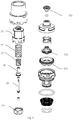
Fig. 2 illustrates an exploded view of the push switch valve core ofEmbodiment 1 of the present disclosure; -
Fig. 3 illustrates a cross-sectional view of the push switch valve core ofEmbodiment 1 of the present disclosure when water is stopped; -
Fig. 4 illustrates a cross-sectional view of the push switch valve core ofEmbodiment 1 of the present disclosure when the water is opened; -
Fig. 5 illustrates a cross-sectional view of a push operate member of Embodiment 1 of the present disclosure; -
Fig. 6 illustrates a schematic view of a low-position positioning member ofEmbodiment 1 of the present disclosure; -
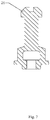
Fig. 7 illustrates a cross-sectional view of a pull rod ofEmbodiment 1 of the present disclosure; -
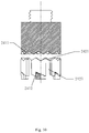
Figs. 8-10 illustrate schematic views ofEmbodiment 1 of the present disclosure when the push operate member and the low-position positioning member move from a high position to a low position; -
Fig. 11 illustrates a schematic view of a faucet ofEmbodiment 1 of the present disclosure; -
Fig. 12 illustrates a schematic view of a faucet ofEmbodiment 2 of the present disclosure. - The technical solutions of the embodiments of the present disclosure will be clearly and completely described below in combination with the drawings in embodiments of the present disclosure. It is obvious that the embodiments described below are merely some embodiments of the present disclosure rather than all embodiments. it is intended that the scope of the present disclosure cover all other embodiments obtained based on the embodiments of the present disclosure by those skilled in the art without creative work.
- Referring to
Fig. 11 , this embodiment provides a fixed water outflow faucet, and a push switch valve core 2 (i.e., push button valve core) is disposed on afaucet body 1. - Further, referring to
Figs. 1-10 , the pushswitch valve core 2 comprises avalve body 21, aswitch shaft 22, asealing member 23 and a push switch 24 (i.e., push button). - The
push switch 24 drives the sealingmember 23 to move along an axial direction of thevalve body 21 to open or close a water outlet of thevalve body 21 through theswitch shaft 22. - In this embodiment, the
push switch 24 comprises a push operatemember 241 and a low-position positioning member 242. - The push operate
member 241 moves between a high position or a low position in the axial direction under an external force; the push operatemember 241 comprises a rotating divertingmember 2411 configured to cooperate with the low-position positioning member 242 and a limitingmember 2412 configured to be locked to the low-position positioning member 242. - The low-
position positioning member 242 comprises a diverting matchingmember 2421 and a limiting matchingmember 2422 disposed up and down in the axial direction and a giving passage or passage oraxial passage 2423 penetrating in the axial direction. - Referring to
Fig. 8 , when the push operatemember 241 is in the high position, the limitingmember 2412 is aligned with the givingpassage 2423, and the rotating divertingmember 2411 is separated from the diverting matchingmember 2421 at a certain distance in the axial direction; referring toFig. 9 , when the push operatemember 241 is in the low position, the limitingmember 2412 passes through thegiving passage 2423. Referring toFig. 10 , the rotating divertingmember 2411 cooperates with the diverting matchingmember 2421 to drive the low-position positioning member 242 to rotate about the axial direction at a certain angle, so that thelimiting member 2412 and the limiting matchingmember 2422 are upwardly limited along the axial direction. - In the
push switch 24, the push operatemember 241 can be switched between the high position and the low position due to two components being consisted of the push operatemember 241 and the low-position positioning member 242. - In detail, in this embodiment, the rotating
diverting member 2411 comprises a plurality of first ratchet wheelinclined surfaces 24111, and the diverting matchingmember 2421 comprises a plurality of first ratchet wheel matching inclined surfaces 24211 (i.e., a plurality of first ratchet wheel inclined surfaces). The plurality of first ratchet wheelinclined surfaces 24111 cooperate with the plurality of first ratchet wheel matchinginclined surfaces 24211 to drive the low-position positioning member 242 to rotate at the certain angle in the axial direction. The low-position positioning member 242 is a rotating ratchet wheel, and a side wall of which is circumferentially disposed with a plurality of ratchet blocks at intervals; thegiving passage 2423 is defined between two adjacent ratchet blocks. - A side of the ratchet blocks facing the push operate
member 241 is disposed with the divertingmatching member 2421. - The limiting
member 2412 comprises a plurality of second ratchet wheelinclined surfaces 24121, and the limitingmatching member 2422 comprises a plurality of second ratchet wheel matching inclined surfaces (i.e., a plurality of second ratchet wheel inclined surfaces); a side of the ratchet blocks away from the push operatemember 241 is disposed with the limitingmatching member 2422. - The push operate
member 241 is circumferentially disposed with a plurality of ribs disposed below the rotating divertingmember 2411 along the axial direction; the plurality of ribs define the limitingmember 2412, and an upper surface of the limitingmember 2412 disposed in the axial direction is disposed with the second ratchet wheel inclined surfaces 24121. - When being operated, the push operate
member 241 is firstly pressed, at this time, the ribs are disposed in therotating ratchet wheel 242 through the givingpassage 2423; therotating ratchet wheel 242 remains stationary, and the push operatemember 241 moves downward along the axial direction. Referring toFig. 9 , when the push operatemember 241 moves to enable the first ratchet wheelinclined surfaces 24111 of the rotating divertingmember 2411 to abut the first ratchet wheel matchinginclined surfaces 24211 of the divertingmatching member 2421, the ribs passes through the givingpassage 2423. Push force generated due to the ratchet wheel inclined surfaces pushing the ratchet wheel matching inclined surfaces pushes therotating ratchet wheel 242 to rotate. After therotating ratchet wheel 242 rotates one of the first ratchet wheel inclined surfaces, the push operatemember 241 and therotating ratchet wheel 242 are released from a cooperation of the pushing, referring toFig. 10 , after the user releases the push operatemember 241, the ribs are configured to cooperate with and be limited to the ratchet blocks through a cooperation between the second ratchet wheel inclined surfaces and the second ratchet wheel matching inclined surfaces, so that the push operatemember 241 is secured in the low position. - This embodiment further comprises a
work spring 25, one end of thework spring 25 is disposed on thevalve body 21 and defines a fixed end, and the other end abuts the push operatemember 241; when the push operatemember 241 is in the low position or the high position, thework spring 25 is always in a compressed state. When the push operatemember 241 is in the high position, it abuts thevalve body 21, so that the push operatemember 241 will not shake. - In this embodiment, the push operate
member 241 is connected to theswitch shaft 22 by apull rod 26, so that thepush switch 24 is interlocked to theswitch shaft 22. In detail, the push operatemember 241 is disposed with a through passage in the axial direction, and an inner wall of the through passage radially extends to define a limiting protruding platform; an upper end of thepull rod 26 radially extends outward to define a limiting surface. In this way, an end of thepull rod 26 passes through the limiting protruding platform and is then downwardly interlocked along the axial direction of the push operatemember 241 due to the limiting surface and the limiting protruding surface. In addition, a lower end of thepull rod 26 is an open surface in communication with an installation cavity disposed in thepull rod 26, so that thepull rod 26 is interlocked to theswitch shaft 22. An upper end of theswitch shaft 22 is disposed in the installation cavity through the open surface and is fixedly connected to thepull rod 26. - In addition, in this embodiment, a water shut-off
spring 27 is further disposed between thevalve body 21 and thepull rod 26 to ensure the sealingmember 23 to seal the water outlet when water is stopped. Thepull rod 26 can be secured at a water shut-off position due to elastic reset force of the water shut-offspring 27, so that the sealingmember 23 can reliably seal the water outlet. - In this embodiment, the sealing
member 23 comprises a sealingcup 231 and a sealingplug 232 that is disposed on a lower end of theswitch shaft 22; when the push operatemember 241 moves to the low position, the sealing plug 232 seals a pressure relief hole of the sealingcup 231, a pressure of stored water in apressure holding cavity 235 disposed between the sealingcup 231 and thevalve body 21 increases, and the sealingcup 231 is driven to move downward along the axial direction of thevalve body 21 to close the water outlet. - When the push operate
member 241 moves to the high position, the sealingplug 232 opens thepressure relief hole 233 of the sealingcup 231, a pressure of relief water in the pressure holding cavity disposed between the sealingcup 231 and thevalve body 21 decreases, so that the sealingcup 231 is driven to move upward along the axis of thevalve body 21 to open the water outlet. - In this embodiment, the
switch shaft 22 is interlocked to a sealingcup base 234 disposed with the sealingcup 231. When theshift shaft 22 moves upward, the sealingcup base 234 drives the sealingcup 231 to open the water outlet. When theshift shaft 22 moves upward, the sealingcup base 234 accordingly moves upward to drive the sealingcup 231 to open the water outlet due to the sealingcup base 234 being interlocked to theswitch shaft 22, the water outlet is ensured to be also opened in a low pressure, and large flow is ensured when being in the low pressure. In detail, a side wall of theswitch shaft 22 radially extends outward to define a protruding platform, and the sealingcup base 234 is disposed with a buckle structure. When theswitch shaft 22 moves upward, the sealingcup base 234 is driven to accordingly move upward due to the protruding platform and the buckle structure. - This embodiment differs from
Embodiment 1 in that the faucet in this embodiment is a pull-out faucet, referring toFig. 12 , the rest is the same asEmbodiment 1 and will not be further described. - In the description of this specification, the terms "embodiment", "example", "detailed embodiment", etc. means that at least one of the embodiment or the example of the present disclosure comprises detailed feature, structure, material or characteristic described in combination with the embodiment or the example. In this specification, the brief description of the above-mentioned terms do not necessarily refer to the same embodiment or the example. Further, the detailed features, the structures, the materials or the characteristics can be appropriately combined to any one or multiple embodiments or examples.
- The invention may be summarized as follows: The present disclosure discloses a push switch, which comprises a push operate member and a low-position positioning member. The push operate member moves between a high position or a low position along an axial direction; the push operate member comprises a rotating diverting member configured to cooperate with the low-position positioning member and a limiting member configured to be locked to the low-position positioning member. The low-position positioning member comprises a diverting matching member and a limiting matching member disposed up and down along the axial direction and a giving passage penetrating in the axial direction. When the push operate member is disposed in the high position, the limiting member is aligned with the giving passage, and the diverting member is separated from the diverting matching member by a certain distance along the axial direction; when the push operate member is disposed in the low position, the limiting member passes through the giving passage, and the diverting member cooperates with the diverting matching member to drive the low-position positioning member to rotate about the axial direction at a certain angle, so that the limiting member and the limiting matching member are upwardly limited along the axial direction. In the push switch, an up-down push switching can be achieved by two parts, and the structure is simple and compact. The present disclosure further discloses push switch valve core and a faucet.
- The above-mentioned preferred published embodiments of the present disclosure merely help to describe the present disclosure. The preferred embodiment does not describe all details, and the embodiments of the disclosure is not only limited thereto. It is obvious that many modifications and variations can be made according to the specification. The embodiments selected and further described in this specification better explain the principles and practical applications of the present disclosure, so that those skilled in the art can well understand and utilize the present disclosure. The present disclosure is only limited by the claims, the scope and equivalents.
Claims (11)
- A push switch, which comprises a push operate member and a low-position positioning member;
the push operate member moves between a high position or a low position along an axial direction; the push operate member comprises a rotating diverting member configured to cooperate with the low-position positioning member and a limiting member configured to be locked to the low-position positioning member;
the low-position positioning member comprises a diverting matching member and a limiting matching member disposed up and down along the axial direction and a giving passage penetrating in the axial direction;
when the push operate member is disposed in the high position, the limiting member is aligned with the giving passage, and the diverting member is separated from the diverting matching member by a certain distance along the axial direction; when the push operate member is disposed in the low position, the limiting member passes through the giving passage, and the diverting member cooperates with the diverting matching member to drive the low-position positioning member to rotate about the axial direction at a certain angle, so that the limiting member and the limiting matching member are upwardly limited along the axial direction. - The push switch according to claim 1, characterized in that: the rotating diverting member and the diverting matching member are first ratchet wheel inclined surfaces.
- The push switch according to claim 2, characterized in that: the low-position positioning member is a rotating ratchet wheel, a side wall of which is circumferentially disposed with a plurality of ratchet blocks at intervals; the giving passage is defined between two adjacent ratchets blocks;
a side of the ratchet blocks facing the push operate member is disposed with the first ratchet wheel inclined surfaces. - The push switch according to claim 3, characterized in that: the limiting member and the limiting matching member are second ratchet wheel inclined surfaces; a side of the ratchet blocks away from the push operate member is disposed with the second ratchet wheel inclined surfaces.
- The push switch according to claim 4, characterized in that: the push operate member is circumferentially disposed with a plurality of ribs disposed below the first ratchet wheel inclined surface along the axial direction; upper surfaces of the ribs disposed along the axial direction are disposed with the second ratchet wheel inclined surfaces.
- The push switch according to any one or more of claims 1 to 5, further comprising a work spring, one end of the work spring is a fixed end, and the other end abuts the push operate member; when the push operate member is in the low position or the high position, the work spring is always in a compressed state.
- A push switch valve core, which comprises a valve body, a switch shaft, a sealing member, and the push switch according to any one or more of claims 1 to 6;
the push operate member drives the sealing member to move along an axial direction of the valve body to open or close a water outlet of the valve body by the switch shaft. - The push switch valve core according to claim 7, characterized in that: the sealing member comprises a sealing cup and a sealing plug that is disposed at an end of the switch shaft;
when the push operate member moves to the low position, the sealing plug seals a pressure relief hole of the sealing cup, pressure of stored water in a pressure holding cavity disposed between the sealing cup and the valve body increases, and the sealing cup is driven to move downward along the axial direction of the valve body to close the water outlet;
when the push operate member moves to the high position, the sealing plug opens the pressure relief hole of the sealing cup, pressure of relief water in the pressure holding cavity disposed between the sealing cup and the valve body decreases, and the sealing cup is driven to move upward along the axial direction of the valve body to open the water outlet. - The push switch valve core according to claim 8, characterized in that: the switch shaft is interlocked to a sealing cup base configured to be disposed with the sealing cup, and when the switch shaft moves upward, the sealing cup base drives the sealing cup to open the water outlet.
- A faucet, which is disposed with the push switch valve core according to any one or more of claims 7 to 9.
- The faucet according to claim 10, characterized in that: the faucet is a fixed faucet or a pull-out faucet.
Applications Claiming Priority (1)
| Application Number | Priority Date | Filing Date | Title |
|---|---|---|---|
| CN202010475379.7A CN113738938B (en) | 2020-05-29 | 2020-05-29 | Push switch, push switch valve core and water outlet faucet |
Publications (2)
| Publication Number | Publication Date |
|---|---|
| EP3916279A1 true EP3916279A1 (en) | 2021-12-01 |
| EP3916279B1 EP3916279B1 (en) | 2024-09-04 |
Family
ID=76217687
Family Applications (1)
| Application Number | Title | Priority Date | Filing Date |
|---|---|---|---|
| EP21176948.4A Active EP3916279B1 (en) | 2020-05-29 | 2021-05-31 | Push switch, push switch valve core and faucet |
Country Status (2)
| Country | Link |
|---|---|
| EP (1) | EP3916279B1 (en) |
| CN (1) | CN113738938B (en) |
Cited By (1)
| Publication number | Priority date | Publication date | Assignee | Title |
|---|---|---|---|---|
| CN114411926A (en) * | 2022-01-26 | 2022-04-29 | 台州尼西卫浴股份有限公司 | Anti-overflow straight-line floor drain core |
Citations (3)
| Publication number | Priority date | Publication date | Assignee | Title |
|---|---|---|---|---|
| US20190178398A1 (en) * | 2017-12-07 | 2019-06-13 | Hansgrohe Se | Valve actuation device and sanitary valve |
| WO2019153670A1 (en) * | 2018-02-07 | 2019-08-15 | 厦门松霖科技股份有限公司 | Switch valve core and water outlet device |
| US20200003312A1 (en) * | 2018-06-27 | 2020-01-02 | Beijing Kohler Ltd. | Flow control switch valve |
Family Cites Families (6)
| Publication number | Priority date | Publication date | Assignee | Title |
|---|---|---|---|---|
| CN108071821B (en) * | 2016-11-07 | 2024-03-22 | 厦门松霖科技股份有限公司 | Water-stopping switching valve core |
| CN107588205A (en) * | 2017-10-20 | 2018-01-16 | 广州海鸥卫浴用品股份有限公司 | Mechanical compression formula switch valve core |
| CN110529624B (en) * | 2018-05-24 | 2022-08-16 | 漳州松霖智能家居有限公司 | Structure for switching water channel and water outlet switching device of combined shower |
| CN110894883A (en) * | 2018-09-13 | 2020-03-20 | 厦门松霖科技股份有限公司 | Waterway switching valve |
| CN212564512U (en) * | 2020-04-17 | 2021-02-19 | 厦门松霖科技股份有限公司 | Push switch rotary temperature-regulating thermostatic valve and faucet device |
| CN212643697U (en) * | 2020-05-29 | 2021-03-02 | 厦门松霖科技股份有限公司 | Push switch, push switch valve core and water outlet faucet |
-
2020
- 2020-05-29 CN CN202010475379.7A patent/CN113738938B/en active Active
-
2021
- 2021-05-31 EP EP21176948.4A patent/EP3916279B1/en active Active
Patent Citations (3)
| Publication number | Priority date | Publication date | Assignee | Title |
|---|---|---|---|---|
| US20190178398A1 (en) * | 2017-12-07 | 2019-06-13 | Hansgrohe Se | Valve actuation device and sanitary valve |
| WO2019153670A1 (en) * | 2018-02-07 | 2019-08-15 | 厦门松霖科技股份有限公司 | Switch valve core and water outlet device |
| US20200003312A1 (en) * | 2018-06-27 | 2020-01-02 | Beijing Kohler Ltd. | Flow control switch valve |
Cited By (1)
| Publication number | Priority date | Publication date | Assignee | Title |
|---|---|---|---|---|
| CN114411926A (en) * | 2022-01-26 | 2022-04-29 | 台州尼西卫浴股份有限公司 | Anti-overflow straight-line floor drain core |
Also Published As
| Publication number | Publication date |
|---|---|
| EP3916279B1 (en) | 2024-09-04 |
| CN113738938B (en) | 2025-05-23 |
| CN113738938A (en) | 2021-12-03 |
Similar Documents
| Publication | Publication Date | Title |
|---|---|---|
| US9615697B2 (en) | Combined pilot valve mechanism and a shower system applied with the combined pilot valve mechanism | |
| CN102720861B (en) | Button switching valve set capable of being automatically reset and shower head using same | |
| CN113963978B (en) | Rotary switch | |
| US11352772B2 (en) | Remote control water outlet device | |
| CN210883393U (en) | Container and mixing device comprising same | |
| CN111577944B (en) | Touch switch in any direction | |
| EP4001715A1 (en) | Flow control device | |
| WO2015103981A1 (en) | Valve | |
| US11850607B2 (en) | Shower device | |
| EP3916279B1 (en) | Push switch, push switch valve core and faucet | |
| CN212643697U (en) | Push switch, push switch valve core and water outlet faucet | |
| EP3896318A1 (en) | Waterway slide switch device and water outlet device | |
| CN107289184A (en) | Side-push type water valve | |
| EP3940277A1 (en) | Water outlet valve with flow rate adjustment and faucet | |
| CN209943770U (en) | Gas circuit interface structure | |
| CN107514470A (en) | A kind of button switches flow controller | |
| EP3779250A1 (en) | Water outlet valve structure and humidifier having same | |
| CN210890123U (en) | a water outlet | |
| CN108150679B (en) | An integrated spool and shower valve | |
| CN118030904A (en) | Water control valve and water outlet device | |
| CN211449759U (en) | Water distributing valve core of water faucet | |
| CN116869341A (en) | Water cup that can be unlocked with one click | |
| CN219943253U (en) | Water outlet device | |
| CN210978579U (en) | Integrated rotary valve core and kitchen faucet with same | |
| JP3136180U (en) | Improved pressure head pump structure |
Legal Events
| Date | Code | Title | Description |
|---|---|---|---|
| PUAI | Public reference made under article 153(3) epc to a published international application that has entered the european phase |
Free format text: ORIGINAL CODE: 0009012 |
|
| STAA | Information on the status of an ep patent application or granted ep patent |
Free format text: STATUS: REQUEST FOR EXAMINATION WAS MADE |
|
| 17P | Request for examination filed |
Effective date: 20210607 |
|
| AK | Designated contracting states |
Kind code of ref document: A1 Designated state(s): AL AT BE BG CH CY CZ DE DK EE ES FI FR GB GR HR HU IE IS IT LI LT LU LV MC MK MT NL NO PL PT RO RS SE SI SK SM TR |
|
| B565 | Issuance of search results under rule 164(2) epc |
Effective date: 20211027 |
|
| RBV | Designated contracting states (corrected) |
Designated state(s): AL AT BE BG CH CY CZ DE DK EE ES FI FR GB GR HR HU IE IS IT LI LT LU LV MC MK MT NL NO PL PT RO RS SE SI SK SM TR |
|
| STAA | Information on the status of an ep patent application or granted ep patent |
Free format text: STATUS: EXAMINATION IS IN PROGRESS |
|
| 17Q | First examination report despatched |
Effective date: 20230328 |
|
| GRAP | Despatch of communication of intention to grant a patent |
Free format text: ORIGINAL CODE: EPIDOSNIGR1 |
|
| STAA | Information on the status of an ep patent application or granted ep patent |
Free format text: STATUS: GRANT OF PATENT IS INTENDED |
|
| INTG | Intention to grant announced |
Effective date: 20240327 |
|
| GRAS | Grant fee paid |
Free format text: ORIGINAL CODE: EPIDOSNIGR3 |
|
| GRAA | (expected) grant |
Free format text: ORIGINAL CODE: 0009210 |
|
| STAA | Information on the status of an ep patent application or granted ep patent |
Free format text: STATUS: THE PATENT HAS BEEN GRANTED |
|
| AK | Designated contracting states |
Kind code of ref document: B1 Designated state(s): AL AT BE BG CH CY CZ DE DK EE ES FI FR GB GR HR HU IE IS IT LI LT LU LV MC MK MT NL NO PL PT RO RS SE SI SK SM TR |
|
| REG | Reference to a national code |
Ref country code: GB Ref legal event code: FG4D |
|
| REG | Reference to a national code |
Ref country code: CH Ref legal event code: EP |
|
| REG | Reference to a national code |
Ref country code: IE Ref legal event code: FG4D |
|
| REG | Reference to a national code |
Ref country code: DE Ref legal event code: R096 Ref document number: 602021018159 Country of ref document: DE |
|
| REG | Reference to a national code |
Ref country code: LT Ref legal event code: MG9D |
|
| REG | Reference to a national code |
Ref country code: NL Ref legal event code: MP Effective date: 20240904 |
|
| PG25 | Lapsed in a contracting state [announced via postgrant information from national office to epo] |
Ref country code: NO Free format text: LAPSE BECAUSE OF FAILURE TO SUBMIT A TRANSLATION OF THE DESCRIPTION OR TO PAY THE FEE WITHIN THE PRESCRIBED TIME-LIMIT Effective date: 20241204 |
|
| PG25 | Lapsed in a contracting state [announced via postgrant information from national office to epo] |
Ref country code: GR Free format text: LAPSE BECAUSE OF FAILURE TO SUBMIT A TRANSLATION OF THE DESCRIPTION OR TO PAY THE FEE WITHIN THE PRESCRIBED TIME-LIMIT Effective date: 20241205 Ref country code: PL Free format text: LAPSE BECAUSE OF FAILURE TO SUBMIT A TRANSLATION OF THE DESCRIPTION OR TO PAY THE FEE WITHIN THE PRESCRIBED TIME-LIMIT Effective date: 20240904 Ref country code: FI Free format text: LAPSE BECAUSE OF FAILURE TO SUBMIT A TRANSLATION OF THE DESCRIPTION OR TO PAY THE FEE WITHIN THE PRESCRIBED TIME-LIMIT Effective date: 20240904 |
|
| PG25 | Lapsed in a contracting state [announced via postgrant information from national office to epo] |
Ref country code: BG Free format text: LAPSE BECAUSE OF FAILURE TO SUBMIT A TRANSLATION OF THE DESCRIPTION OR TO PAY THE FEE WITHIN THE PRESCRIBED TIME-LIMIT Effective date: 20240904 |
|
| PG25 | Lapsed in a contracting state [announced via postgrant information from national office to epo] |
Ref country code: LV Free format text: LAPSE BECAUSE OF FAILURE TO SUBMIT A TRANSLATION OF THE DESCRIPTION OR TO PAY THE FEE WITHIN THE PRESCRIBED TIME-LIMIT Effective date: 20240904 |
|
| PG25 | Lapsed in a contracting state [announced via postgrant information from national office to epo] |
Ref country code: HR Free format text: LAPSE BECAUSE OF FAILURE TO SUBMIT A TRANSLATION OF THE DESCRIPTION OR TO PAY THE FEE WITHIN THE PRESCRIBED TIME-LIMIT Effective date: 20240904 |
|
| PG25 | Lapsed in a contracting state [announced via postgrant information from national office to epo] |
Ref country code: ES Free format text: LAPSE BECAUSE OF FAILURE TO SUBMIT A TRANSLATION OF THE DESCRIPTION OR TO PAY THE FEE WITHIN THE PRESCRIBED TIME-LIMIT Effective date: 20240904 Ref country code: RS Free format text: LAPSE BECAUSE OF FAILURE TO SUBMIT A TRANSLATION OF THE DESCRIPTION OR TO PAY THE FEE WITHIN THE PRESCRIBED TIME-LIMIT Effective date: 20241204 |
|
| PG25 | Lapsed in a contracting state [announced via postgrant information from national office to epo] |
Ref country code: RS Free format text: LAPSE BECAUSE OF FAILURE TO SUBMIT A TRANSLATION OF THE DESCRIPTION OR TO PAY THE FEE WITHIN THE PRESCRIBED TIME-LIMIT Effective date: 20241204 Ref country code: PL Free format text: LAPSE BECAUSE OF FAILURE TO SUBMIT A TRANSLATION OF THE DESCRIPTION OR TO PAY THE FEE WITHIN THE PRESCRIBED TIME-LIMIT Effective date: 20240904 Ref country code: NO Free format text: LAPSE BECAUSE OF FAILURE TO SUBMIT A TRANSLATION OF THE DESCRIPTION OR TO PAY THE FEE WITHIN THE PRESCRIBED TIME-LIMIT Effective date: 20241204 Ref country code: LV Free format text: LAPSE BECAUSE OF FAILURE TO SUBMIT A TRANSLATION OF THE DESCRIPTION OR TO PAY THE FEE WITHIN THE PRESCRIBED TIME-LIMIT Effective date: 20240904 Ref country code: HR Free format text: LAPSE BECAUSE OF FAILURE TO SUBMIT A TRANSLATION OF THE DESCRIPTION OR TO PAY THE FEE WITHIN THE PRESCRIBED TIME-LIMIT Effective date: 20240904 Ref country code: GR Free format text: LAPSE BECAUSE OF FAILURE TO SUBMIT A TRANSLATION OF THE DESCRIPTION OR TO PAY THE FEE WITHIN THE PRESCRIBED TIME-LIMIT Effective date: 20241205 Ref country code: FI Free format text: LAPSE BECAUSE OF FAILURE TO SUBMIT A TRANSLATION OF THE DESCRIPTION OR TO PAY THE FEE WITHIN THE PRESCRIBED TIME-LIMIT Effective date: 20240904 Ref country code: ES Free format text: LAPSE BECAUSE OF FAILURE TO SUBMIT A TRANSLATION OF THE DESCRIPTION OR TO PAY THE FEE WITHIN THE PRESCRIBED TIME-LIMIT Effective date: 20240904 Ref country code: BG Free format text: LAPSE BECAUSE OF FAILURE TO SUBMIT A TRANSLATION OF THE DESCRIPTION OR TO PAY THE FEE WITHIN THE PRESCRIBED TIME-LIMIT Effective date: 20240904 |
|
| REG | Reference to a national code |
Ref country code: AT Ref legal event code: MK05 Ref document number: 1720717 Country of ref document: AT Kind code of ref document: T Effective date: 20240904 |
|
| PG25 | Lapsed in a contracting state [announced via postgrant information from national office to epo] |
Ref country code: NL Free format text: LAPSE BECAUSE OF FAILURE TO SUBMIT A TRANSLATION OF THE DESCRIPTION OR TO PAY THE FEE WITHIN THE PRESCRIBED TIME-LIMIT Effective date: 20240904 |
|
| PG25 | Lapsed in a contracting state [announced via postgrant information from national office to epo] |
Ref country code: PT Free format text: LAPSE BECAUSE OF FAILURE TO SUBMIT A TRANSLATION OF THE DESCRIPTION OR TO PAY THE FEE WITHIN THE PRESCRIBED TIME-LIMIT Effective date: 20250106 Ref country code: IS Free format text: LAPSE BECAUSE OF FAILURE TO SUBMIT A TRANSLATION OF THE DESCRIPTION OR TO PAY THE FEE WITHIN THE PRESCRIBED TIME-LIMIT Effective date: 20250104 |
|
| PG25 | Lapsed in a contracting state [announced via postgrant information from national office to epo] |
Ref country code: SM Free format text: LAPSE BECAUSE OF FAILURE TO SUBMIT A TRANSLATION OF THE DESCRIPTION OR TO PAY THE FEE WITHIN THE PRESCRIBED TIME-LIMIT Effective date: 20240904 Ref country code: RO Free format text: LAPSE BECAUSE OF FAILURE TO SUBMIT A TRANSLATION OF THE DESCRIPTION OR TO PAY THE FEE WITHIN THE PRESCRIBED TIME-LIMIT Effective date: 20240904 |
|
| PG25 | Lapsed in a contracting state [announced via postgrant information from national office to epo] |
Ref country code: EE Free format text: LAPSE BECAUSE OF FAILURE TO SUBMIT A TRANSLATION OF THE DESCRIPTION OR TO PAY THE FEE WITHIN THE PRESCRIBED TIME-LIMIT Effective date: 20240904 Ref country code: AT Free format text: LAPSE BECAUSE OF FAILURE TO SUBMIT A TRANSLATION OF THE DESCRIPTION OR TO PAY THE FEE WITHIN THE PRESCRIBED TIME-LIMIT Effective date: 20240904 |
|
| PG25 | Lapsed in a contracting state [announced via postgrant information from national office to epo] |
Ref country code: CZ Free format text: LAPSE BECAUSE OF FAILURE TO SUBMIT A TRANSLATION OF THE DESCRIPTION OR TO PAY THE FEE WITHIN THE PRESCRIBED TIME-LIMIT Effective date: 20240904 |
|
| PG25 | Lapsed in a contracting state [announced via postgrant information from national office to epo] |
Ref country code: SK Free format text: LAPSE BECAUSE OF FAILURE TO SUBMIT A TRANSLATION OF THE DESCRIPTION OR TO PAY THE FEE WITHIN THE PRESCRIBED TIME-LIMIT Effective date: 20240904 Ref country code: IT Free format text: LAPSE BECAUSE OF FAILURE TO SUBMIT A TRANSLATION OF THE DESCRIPTION OR TO PAY THE FEE WITHIN THE PRESCRIBED TIME-LIMIT Effective date: 20240904 |
|
| REG | Reference to a national code |
Ref country code: DE Ref legal event code: R097 Ref document number: 602021018159 Country of ref document: DE |
|
| PGFP | Annual fee paid to national office [announced via postgrant information from national office to epo] |
Ref country code: DE Payment date: 20250521 Year of fee payment: 5 |
|
| PG25 | Lapsed in a contracting state [announced via postgrant information from national office to epo] |
Ref country code: DK Free format text: LAPSE BECAUSE OF FAILURE TO SUBMIT A TRANSLATION OF THE DESCRIPTION OR TO PAY THE FEE WITHIN THE PRESCRIBED TIME-LIMIT Effective date: 20240904 |
|
| PLBE | No opposition filed within time limit |
Free format text: ORIGINAL CODE: 0009261 |
|
| STAA | Information on the status of an ep patent application or granted ep patent |
Free format text: STATUS: NO OPPOSITION FILED WITHIN TIME LIMIT |
|
| PGFP | Annual fee paid to national office [announced via postgrant information from national office to epo] |
Ref country code: FR Payment date: 20250528 Year of fee payment: 5 |
|
| 26N | No opposition filed |
Effective date: 20250605 |
|
| PG25 | Lapsed in a contracting state [announced via postgrant information from national office to epo] |
Ref country code: SE Free format text: LAPSE BECAUSE OF FAILURE TO SUBMIT A TRANSLATION OF THE DESCRIPTION OR TO PAY THE FEE WITHIN THE PRESCRIBED TIME-LIMIT Effective date: 20240904 |
|
| REG | Reference to a national code |
Ref country code: CH Ref legal event code: H13 Free format text: ST27 STATUS EVENT CODE: U-0-0-H10-H13 (AS PROVIDED BY THE NATIONAL OFFICE) Effective date: 20251223 |
|
| PG25 | Lapsed in a contracting state [announced via postgrant information from national office to epo] |
Ref country code: LU Free format text: LAPSE BECAUSE OF NON-PAYMENT OF DUE FEES Effective date: 20250531 |
|
| PG25 | Lapsed in a contracting state [announced via postgrant information from national office to epo] |
Ref country code: CH Free format text: LAPSE BECAUSE OF NON-PAYMENT OF DUE FEES Effective date: 20250531 |
|
| GBPC | Gb: european patent ceased through non-payment of renewal fee |
Effective date: 20250531 |
|
| REG | Reference to a national code |
Ref country code: BE Ref legal event code: MM Effective date: 20250531 |
|
| PG25 | Lapsed in a contracting state [announced via postgrant information from national office to epo] |
Ref country code: MC Free format text: LAPSE BECAUSE OF FAILURE TO SUBMIT A TRANSLATION OF THE DESCRIPTION OR TO PAY THE FEE WITHIN THE PRESCRIBED TIME-LIMIT Effective date: 20240904 |
|
| PG25 | Lapsed in a contracting state [announced via postgrant information from national office to epo] |
Ref country code: GB Free format text: LAPSE BECAUSE OF NON-PAYMENT OF DUE FEES Effective date: 20250531 |
|
| PG25 | Lapsed in a contracting state [announced via postgrant information from national office to epo] |
Ref country code: IE Free format text: LAPSE BECAUSE OF NON-PAYMENT OF DUE FEES Effective date: 20250531 |
|
| PG25 | Lapsed in a contracting state [announced via postgrant information from national office to epo] |
Ref country code: BE Free format text: LAPSE BECAUSE OF NON-PAYMENT OF DUE FEES Effective date: 20250531 |