EP3916267A1 - Tooth surface shape design support device, gear machining system, and tooth surface shape design support program - Google Patents
Tooth surface shape design support device, gear machining system, and tooth surface shape design support program Download PDFInfo
- Publication number
- EP3916267A1 EP3916267A1 EP21172235.0A EP21172235A EP3916267A1 EP 3916267 A1 EP3916267 A1 EP 3916267A1 EP 21172235 A EP21172235 A EP 21172235A EP 3916267 A1 EP3916267 A1 EP 3916267A1
- Authority
- EP
- European Patent Office
- Prior art keywords
- tooth surface
- surface shape
- principal component
- shape
- tooth
- Prior art date
- Legal status (The legal status is an assumption and is not a legal conclusion. Google has not performed a legal analysis and makes no representation as to the accuracy of the status listed.)
- Withdrawn
Links
Images











Classifications
-
- G—PHYSICS
- G01—MEASURING; TESTING
- G01M—TESTING STATIC OR DYNAMIC BALANCE OF MACHINES OR STRUCTURES; TESTING OF STRUCTURES OR APPARATUS, NOT OTHERWISE PROVIDED FOR
- G01M13/00—Testing of machine parts
- G01M13/02—Gearings; Transmission mechanisms
- G01M13/021—Gearings
-
- G—PHYSICS
- G06—COMPUTING OR CALCULATING; COUNTING
- G06F—ELECTRIC DIGITAL DATA PROCESSING
- G06F30/00—Computer-aided design [CAD]
- G06F30/10—Geometric CAD
- G06F30/17—Mechanical parametric or variational design
-
- B—PERFORMING OPERATIONS; TRANSPORTING
- B23—MACHINE TOOLS; METAL-WORKING NOT OTHERWISE PROVIDED FOR
- B23F—MAKING GEARS OR TOOTHED RACKS
- B23F1/00—Making gear teeth by tools of which the profile matches the profile of the required surface
- B23F1/06—Making gear teeth by tools of which the profile matches the profile of the required surface by milling
-
- F—MECHANICAL ENGINEERING; LIGHTING; HEATING; WEAPONS; BLASTING
- F16—ENGINEERING ELEMENTS AND UNITS; GENERAL MEASURES FOR PRODUCING AND MAINTAINING EFFECTIVE FUNCTIONING OF MACHINES OR INSTALLATIONS; THERMAL INSULATION IN GENERAL
- F16H—GEARING
- F16H55/00—Elements with teeth or friction surfaces for conveying motion; Worms, pulleys or sheaves for gearing mechanisms
- F16H55/02—Toothed members; Worms
- F16H55/08—Profiling
-
- G—PHYSICS
- G01—MEASURING; TESTING
- G01M—TESTING STATIC OR DYNAMIC BALANCE OF MACHINES OR STRUCTURES; TESTING OF STRUCTURES OR APPARATUS, NOT OTHERWISE PROVIDED FOR
- G01M13/00—Testing of machine parts
- G01M13/02—Gearings; Transmission mechanisms
- G01M13/028—Acoustic or vibration analysis
-
- G—PHYSICS
- G06—COMPUTING OR CALCULATING; COUNTING
- G06F—ELECTRIC DIGITAL DATA PROCESSING
- G06F30/00—Computer-aided design [CAD]
- G06F30/20—Design optimisation, verification or simulation
-
- G—PHYSICS
- G06—COMPUTING OR CALCULATING; COUNTING
- G06T—IMAGE DATA PROCESSING OR GENERATION, IN GENERAL
- G06T7/00—Image analysis
- G06T7/0002—Inspection of images, e.g. flaw detection
- G06T7/0004—Industrial image inspection
-
- G—PHYSICS
- G06—COMPUTING OR CALCULATING; COUNTING
- G06T—IMAGE DATA PROCESSING OR GENERATION, IN GENERAL
- G06T7/00—Image analysis
- G06T7/50—Depth or shape recovery
-
- F—MECHANICAL ENGINEERING; LIGHTING; HEATING; WEAPONS; BLASTING
- F16—ENGINEERING ELEMENTS AND UNITS; GENERAL MEASURES FOR PRODUCING AND MAINTAINING EFFECTIVE FUNCTIONING OF MACHINES OR INSTALLATIONS; THERMAL INSULATION IN GENERAL
- F16H—GEARING
- F16H57/00—General details of gearing
- F16H2057/0087—Computer aided design [CAD] specially adapted for gearing features; Analysis of gear systems
-
- G—PHYSICS
- G06—COMPUTING OR CALCULATING; COUNTING
- G06T—IMAGE DATA PROCESSING OR GENERATION, IN GENERAL
- G06T2207/00—Indexing scheme for image analysis or image enhancement
- G06T2207/30—Subject of image; Context of image processing
- G06T2207/30108—Industrial image inspection
- G06T2207/30164—Workpiece; Machine component
Definitions
- the present disclosure relates to a tooth surface shape design support device, a gear machining system, and a tooth surface shape design support program.
- Patent Document 1 discloses a gear manufacturing method for reducing meshing vibration force.
- the meshing vibration force is evaluated while changing, as modification parameters of the gear, a cut amount in the tooth profile direction and a cut length in the tooth height direction, and the modification parameter that minimizes the meshing vibration force is determined.
- Patent Document 1 JP 2006-242211 A
- a gear for transmission is required to achieve both an improvement in load capacity and an improvement in quietness.
- the complicated tooth surface shape cannot be evaluated in the method of performing the shape evaluation while changing the simple modification parameter as described in Patent Document 1, for example, it is difficult to design the complicated tooth surface shape so as to achieve both the improvement in the load capacity of the gear and the improvement in quietness.
- an object of the present disclosure is to provide a tooth surface shape design support device and a gear machining system capable of efficiently evaluating a complicated tooth surface shape of a gear with a small amount of calculation.
- a tooth surface shape design support device for supporting design of a tooth surface shape of a gear including, a principal component shape data acquisition unit configured to acquire a plurality of principal component shape data obtained by performing principal component analysis on a tooth surface shape sample data group including a plurality of tooth surface shape sample data indicating samples of the tooth surface shape, and a tooth surface shape evaluation unit configured to evaluate a tooth surface shape defined by using the plurality of principal component shape data acquired by the principal component shape data acquisition unit.
- a tooth surface shape design support program is a tooth surface shape design support program for supporting design of a tooth surface shape of a gear, the program causing a computer to execute the steps of, acquiring a plurality of principal component shape data obtained by principal component analysis on a tooth surface shape sample data group including a plurality of tooth surface shape sample data indicating samples of the tooth surface shape, and evaluating the tooth surface shape defined using the plurality of principal component shape data.
- a tooth surface shape design support device and a gear machining system capable of efficiently evaluating a complicated tooth surface shape of a gear with a small amount of calculation.
- an expression of relative or absolute arrangement such as “in a direction”, “along a direction”, “parallel”, “orthogonal”, “centered”, “concentric” or “coaxial” shall not be construed as indicating only the arrangement in a strict literal sense, but also includes a state where the arrangement is relatively displaced by a tolerance, or by an angle or a distance within a range where the same function can be achieved.
- an expression of an equal state such as “same”, “equal”, “uniform” or the like shall not be construed as indicating only the state in which the feature is strictly equal, but also includes a state in which there is a tolerance or a difference within a range where the same function can be achieved.
- an expression of a shape such as a rectangular shape, a cylindrical shape or the like shall not be construed as only the geometrically strict shape, but also includes a shape with unevenness, chamfered corners or the like within the range where the same effect can be achieved.
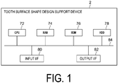
- FIG. 1 is a block diagram illustrating a schematic hardware configuration of a tooth surface shape design support device 2 according to an embodiment.
- FIG. 2 is a block diagram illustrating a functional schematic configuration of the tooth surface shape design support device 2 illustrated in FIG. 1 .
- the tooth surface shape design support device 2 is used to support the design of the tooth surface shape of a gear.
- the tooth surface shape design support device 2 includes a central processing unit (CPU) 72, a random access memory (RAM) 74, a read only memory (ROM) 76, a hard disk drive (HDD) 78, an input I/F 80, and an output I/F 82, and is configured using a computer in which these components are connected to each other via a bus 84.
- the hardware configuration of the tooth surface shape design support device 2 is not limited to the above, and may be configured by a combination of a control circuit and a storage device.
- the tooth surface shape design support device 2 is configured by a computer executing a program (tooth surface shape design support program) that realizes each function of the tooth surface shape design support device 2.
- each unit in the tooth surface shape design support device 2 described below is realized by, for example, loading a program held in a ROM 76 into the RAM 74 and executing the program by the CPU 72, and reading and writing data in the RAM 74 and the ROM 76.
- the tooth surface shape design support device 2 includes a sample data generation unit 4, the principal component shape data acquisition unit 6, a tooth surface shape evaluation unit 8, and the tooth surface shape determination unit 10. The functions of each component illustrated in FIG. 2 will be described below.
- FIG. 3 is a diagram illustrating a processing flow for evaluating a tooth surface shape of a gear.
- the sample data generation unit 4 generates the tooth surface shape sample data group Dg as illustrated in FIG. 4 using at least one tooth surface modification parameter based on general tooth surface design guidelines (low stress design and low vibration force design).
- the tooth surface shape sample data group Dg illustrated in FIG. 4 includes tooth surface shape sample data D1 to D15 indicating samples of tooth surface shape, and each of the tooth surface shape sample data D1 to D15 indicates a three-dimensional shape of a tooth surface.
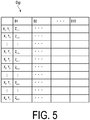
- the tooth surface shape sample data group Dg is, for example, as illustrated in FIG. 5 , point sequence data (matrix data) showing the Z coordinate Z i,j of the tooth surface in each position coordinate (X i ,Y j ) for each of the tooth surface shape sample data D1 to D15.
- the at least one tooth surface modification parameter includes, for example, at least one of a tooth profile modification, a tooth trace modification, a bias modification, a pressure angle modification, and a helix angle modification.
- the tooth profile modification includes, for example, at least one of a tooth tip modification and a tooth root modification
- the tooth trace modification includes, for example, at least one of crowning and end relief.
- the low stress design includes a design in which the tooth tip, the tooth root, and the end portion of the tooth trace are modified so as not to come into contact with each other, and the amount of modification substantially matches the amount of warping of the tooth.
- the low vibration force design includes a design in which the modification is performed such that rigidity variation caused by the change in the number of engaged teeth is canceled.
- the principal component shape data acquisition unit 6 performs principal component analysis (eigenvalue orthogonal analysis) on the tooth surface shape sample data group Dg. Then, in the S13, the principal component shape data acquisition unit 6 extracts and acquires a plurality of principal component shape data u k from the result of the principal component analysis on the tooth surface shape sample data group Dg.
- principal component analysis eigenvalue orthogonal analysis
- FIG. 6 illustrates an example of a plurality of principal component shape data u k acquired by the principal component shape data acquisition unit 6.
- k is the order of the principal component shape
- k is an integer from 1 to 6.
- first-order principal component shape data u 1 , second-order principal component shape data u 2 , third-order principal component shape data u 3 , fourth-order principal component shape data u 4 , fifth-order principal component shape data u 5 , and sixth-order principal component shape data u 6 are illustrated, which are extracted from the result of the principal component analysis on the tooth surface shape sample data group Dg.
- FIG. 1 first-order principal component shape data u 1
- second-order principal component shape data u 2 third-order principal component shape data u 3
- fourth-order principal component shape data u 4 fifth-order principal component shape data u 5
- sixth-order principal component shape data u 6 are illustrated, which are extracted from the result of the principal component analysis on the tooth surface shape sample data group Dg.
- each of the principal component shape data u 1 to u 6 is point sequence data (matrix data) indicating the position Z i,j of the tooth surface at each position coordinate (X i ,Y j ).
- matrix data matrix data
- i is an integer from 1 to w
- j is an integer from 1 to h.
- the tooth surface shape evaluation unit 8 evaluates the tooth surface shape ⁇ defined using a linear combination of the plurality of principal component shape data u k acquired by the principal component shape data acquisition unit 6.
- v is average shape of the tooth surface shape indicated by each of the tooth surface shape sample data D1 to D15
- ⁇ k is a linear combination coefficient of the principal component shape data u k
- n is the maximum order (6 in the above example) of the principal component shape data extracted from the result of the principal component analysis.
- the tooth surface shape evaluation unit 8 performs gear analysis on the gear having the tooth surface shape ⁇ , and evaluates the tooth surface shape ⁇ by evaluating stress (e.g., surface pressure and tooth root stress) and vibration force generated in the gear.
- stress e.g., surface pressure and tooth root stress
- the tooth surface shape evaluation unit 8 evaluates a plurality of tooth surface shapes ⁇ obtained by changing the linear combination coefficient ⁇ k .
- the tooth surface shape determination unit 10 determines an optimum tooth surface shape (e.g., see FIG. 8 ) that can achieve both low stress and low vibration force based on the result (result of parameter study with linear combination coefficient ⁇ k as parameter) of evaluation by the tooth surface shape evaluation unit 8 on the plurality of tooth surface shapes ⁇ obtained by changing the linear combination coefficient ⁇ k .
- an optimum tooth surface shape capable of achieving both improvement in load capacity and improvement in quietness is determined.
- the tooth surface shape evaluation unit 8 and the tooth surface shape determination unit 10 may appropriately use an optimization method such as a Monte Carlo method.
- FIG. 9 is a block diagram illustrating a modified example of the tooth surface shape design support device 2 described with reference to FIG. 2 or the like.
- the tooth surface shape design support device 2 illustrated in FIG. 9 is different from the tooth surface shape design support device 2 illustrated in FIG. 2 in that the tooth surface shape design support device 2 illustrated in FIG. 9 includes a symmetrical tooth surface shape generation unit 12.
- the same reference sign as that of each configuration of the tooth surface shape design support device 2 illustrated in FIG. 2 or the like indicate the same configuration as that of each configuration of the tooth surface shape design support device 2 illustrated in FIG. 2 or the like unless otherwise specified, and description thereof will be omitted.
- the symmetrical tooth surface shape generation unit 12 generates a plurality of tooth surface shape data ⁇ k having symmetrical shapes based on each of the plurality of principal component shape data u k acquired by the principal component shape data acquisition unit 6.
- the principal component shape indicated by the principal component shape data u k is also referred to as a principal component shape u k for convenience.
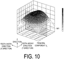
- the symmetrical tooth surface shape generation unit 12 For each of the principal component shape data u k acquired by the principal component shape data acquisition unit 6, as expressed in the following Equation (b1), the symmetrical tooth surface shape generation unit 12 generates tooth surface shape data ⁇ 1_i,j having a symmetrical shape by averaging Z coordinates at symmetrical positions in the tooth surface with the central position M1 (see FIG. 10 ) of the tooth surface in the tooth height direction as an axis of symmetry.
- ⁇ 1 _i , j Z i , j + Z i , h ⁇ j + 1 / 2
- the symmetrical tooth surface shape generation unit 12 For each of the principal component shape data u k acquired by the principal component shape data acquisition unit 6, as expressed in the following Equation (b2), the symmetrical tooth surface shape generation unit 12 generates tooth surface shape data ⁇ 2_i,j having a symmetrical shape by averaging Z coordinates at symmetrical positions in the tooth surface with the central position M2 (see FIG. 12 ) of the tooth surface in the tooth width direction as an axis of symmetry.
- ⁇ 2 _i , j Z i , j + Z w ⁇ i + 1 , j / 2
- Z (w - i + 1),j is the Z coordinate of the principal component shape u k at the symmetrical position (X (w - i + 1), Y j ) of the position (X i ,Y j ) with the central position M2 as the axis of symmetry.
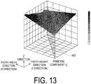
- the symmetrical tooth surface shape generation unit 12 For each of the principal component shape data u k acquired by the principal component shape data acquisition unit 6, as expressed in the following Equation (b3), the symmetrical tooth surface shape generation unit 12 generates tooth surface shape data ⁇ 3_i,j having a symmetrical shape by averaging Z coordinates at symmetrical positions in the tooth surface with a diagonal M3 (see FIG. 13 ) intersecting each of the tooth width direction and the tooth height direction of the tooth surface as an axis of symmetry.
- ⁇ 3 _i , j Z i , j + Z j , i / 2
- Z j,i is the Z coordinate of the principal component shape u k at the symmetrical position (X j , Y i ) of the position (X i , Y j ) with the diagonal M3 as an axis of symmetry.
- the symmetrical tooth surface shape generation unit 12 For each of the principal component shape data u k acquired by the principal component shape data acquisition unit 6, as expressed in the following Equation (b4), the symmetrical tooth surface shape generation unit 12 generates tooth surface shape data ⁇ 4_i,j having a symmetrical shape by averaging Z coordinates at symmetrical positions in the tooth surface with a diagonal M4 (not illustrated) intersecting each of the tooth width direction and the tooth height direction of the tooth surface as an axis of symmetry.
- ⁇ 4 _i , j Z i , j + Z w ⁇ i + 1 , h ⁇ j + 1 / 2
- Z (w - i + 1),(h - j + 1) is the Z coordinate of the principal component shape u k at the symmetrical position (Y (w - i + 1), X (h - j + 1) ) of the position (X i ,Y j ) with the diagonal M4 as an axis of symmetry.
- the symmetrical tooth surface shape generation unit 12 selects the axis of symmetry having the smallest sum of differences between the principal component shape u k and each of the symmetrical shapes ⁇ 1_i, j to ⁇ 4_i,j as expressed in the following Equation (c). Then, data ⁇ i,j of a tooth surface shape having a symmetrical shape using the selected axis of symmetry are determined.
- ⁇ i , j min ⁇ Z i , j ⁇ ⁇ 1 _i , j , ⁇ Z i , j ⁇ ⁇ 2 _i , j , ⁇ Z i , j ⁇ ⁇ 3 _i , j , ⁇ Z i , j ⁇ ⁇ 4 _i , j
- the tooth surface shape evaluation unit 8 evaluates the tooth surface shape ⁇ defined by the following Equation (d) using the linear combination of the tooth surface shape data ⁇ i,j having the symmetrical shape determined by the symmetrical tooth surface shape generation unit 12.
- v is the average shape of the tooth surface shapes indicated by each of the tooth surface shape sample data D1 to D15
- ⁇ k is the tooth surface shape data ⁇ i,j having the symmetrical shape determined using the principal component shape u k
- ⁇ k is the linear combination coefficient of the tooth surface shape data ⁇ k having the symmetrical shape
- n is the maximum order (6 in the above example) of the principal component shape data extracted from the result of the principal component analysis.
- the tooth surface shape evaluation unit 8 performs gear analysis on the gear having the tooth surface shape ⁇ , and evaluates the tooth surface shape ⁇ by stress (e.g., surface pressure and tooth root stress) and vibration force generated in the gear.
- stress e.g., surface pressure and tooth root stress
- the tooth surface shape evaluation unit 8 evaluates a plurality of tooth surface shapes ⁇ obtained by changing the linear combination coefficient of the tooth surface shape data ⁇ i,j .
- the tooth surface shape determination unit 10 determines an optimum tooth surface shape capable of achieving both low stress and low vibration force based on the evaluation result by the tooth surface shape evaluation unit 8 with respect to a plurality of tooth surface shapes ⁇ obtained by changing the linear combination coefficient of the tooth surface shape data ⁇ i,j .
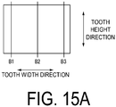
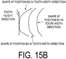
- the gear analysis is performed using the principal component shape obtained by symmetrically shaping and simplifying the shape, even when the generated optimum tooth surface shape is represented in a drawing by a modified shape represented by several lines in the tooth width direction (e.g., modified shapes at the positions A1, A2, and A3 in the tooth height direction as illustrated in FIGS. 14A and 14B ) or by a modified shape represented by several lines in the tooth height direction (e.g., modified shapes at the positions B1, B2, and B3 in the tooth width direction as illustrated in FIGS. 15A and 15B ), the difference from the optimum tooth surface shape becomes small because the section between the indicated shape data is subjected to spline interpolation or the like during machining. Therefore, it becomes easy to describe in the drawings, instruct the manufacturing department or supplier, and manage the machining accuracy.
- a modified shape represented by several lines in the tooth width direction e.g., modified shapes at the positions A1, A2, and A3 in the tooth height direction as illustrated in FIGS. 14A and 14B
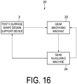
- FIG. 16 is a block diagram illustrating a schematic configuration of the gear machining system 20 to which the tooth surface shape design support device 2 illustrated in FIG. 2 or FIG. 9 can be applied.
- a gear machining system 20 illustrated in FIG. 16 includes a tooth surface shape design support device 2, a gear machining machine 22, and a gear measuring machine 24.
- the gear machining machine 22 is configured to machine the tooth surface of the gear based on the optimum tooth surface shape determined by the tooth surface shape design support device 2.
- the gear measuring machine 24 measures the actual tooth surface shape of the gear (workpiece) machined by the gear machining machine 22, and transmits measurement data of the tooth surface shape to the tooth surface shape design support device 2.
- the tooth surface shape design support device 2 analyzes the surface pressure, the tooth root stress, and the vibration force reflecting the measured actual tooth surface shape, and uses them for designing the tooth surface shape. Further, the gear machining machine 22 can reduce the machining error by performing the tooth surface correction and the dimension correction of the gear based on the measurement data of the tooth surface shape measured by the gear measuring machine 24.
- the gear machining machine 22 illustrated in FIG. 16 may be a five-axis machining machine.
- the tooth surface shape determined by the tooth surface shape design support device 2 is a complicated shape, the tooth surface shape can be accurately realized.
- the gear machining machine 22 is preferably configured to machine the tooth surface such that the machined pattern intersects with the meshing advancing direction of the gear, and more preferably configured to machine the tooth surface such that the machined pattern is orthogonal to the meshing advancing direction of the gear. That is, the tool path (the path along which the tool moves when machining is performed) of the gear machining machine 22 is preferably set so as to intersect with the meshing advancing direction of the gear, and more preferably set so as to be orthogonal to the meshing advancing direction of the gear.
- the gear machining machine 22 machines the tooth surface so that a machined pattern is formed along the axial direction as illustrated in FIG. 18B .
- the gear machining machine 22 machines the tooth surface so that a machined pattern is formed along an oblique direction intersecting each of the axial direction and the radial direction as illustrated in FIG. 17B .
- the angle of the meshing advancing direction changes depending on the helix angle of the helical gear.
- the present disclosure is not limited to the above-described embodiments, and includes embodiments obtained by modifying the above-described embodiments and embodiments obtained by appropriately combining these embodiments.
- the symmetrical tooth surface shape generation unit 12 has selected, from among the central positions M1 and M2, and diagonals M3 and M4, the axis of symmetry having the smallest sum of differences between the principal component shape u k and each of the symmetrical shapes ⁇ 1_i,j to ⁇ 4_i,j , and then, tooth surface shape data ⁇ i,j having a symmetrical shape using the selected axis of symmetry have been determined.
- the symmetrical tooth surface shape generation unit 12 can generate a plurality of tooth surface shape data ⁇ i,j having a symmetrical shape by averaging the Z coordinates at symmetrical positions in the tooth surface, with at least one of the central positions M1 and M2, and the diagonals M3 and M4 as an axis of symmetry for each of the principal component shape data u k .
- the symmetrical tooth surface shape generation unit 12 may generate only one of the symmetrical shapes ⁇ 1_i,j to ⁇ 4_i,j as the tooth surface shape data ⁇ i,j having the symmetrical shape, and the tooth surface shape evaluation unit 8 may evaluate the data ⁇ i,j .
- the principal component analysis on the tooth surface shape sample data group Dg is performed by the principal component shape data acquisition unit 6, but the principal component analysis on the tooth surface shape sample data group Dg may be performed outside the tooth surface shape design support device 2. That is, principal component analysis may be performed on the tooth surface shape sample data group Dg outside the tooth surface shape design support device 2, and the principal component shape data acquisition unit 6 may acquire the principal component shape data u k extracted from the result of the principal component analysis.
- the tooth surface shape design support program described in the above (10) as compared with the case where the tooth surface shape is evaluated by using all the coordinates of the tooth surface shape as parameters, the tooth surface shape defined by using the plurality of principal component shape data obtained by the principal component analysis with respect to the tooth surface shape sample data group is evaluated and thus it is possible to efficiently evaluate the complicated tooth surface shape with a small amount of calculation.
Landscapes
- Engineering & Computer Science (AREA)
- Physics & Mathematics (AREA)
- General Physics & Mathematics (AREA)
- Theoretical Computer Science (AREA)
- General Engineering & Computer Science (AREA)
- Geometry (AREA)
- Mechanical Engineering (AREA)
- Computer Vision & Pattern Recognition (AREA)
- Evolutionary Computation (AREA)
- Computer Hardware Design (AREA)
- Computational Mathematics (AREA)
- Quality & Reliability (AREA)
- Mathematical Analysis (AREA)
- Mathematical Optimization (AREA)
- Pure & Applied Mathematics (AREA)
- Acoustics & Sound (AREA)
- Testing Of Devices, Machine Parts, Or Other Structures Thereof (AREA)
- Gears, Cams (AREA)
Abstract
Description
- The present disclosure relates to a tooth surface shape design support device, a gear machining system, and a tooth surface shape design support program.
-
Patent Document 1 discloses a gear manufacturing method for reducing meshing vibration force. - In the gear manufacturing method described in
Patent Document 1, the meshing vibration force is evaluated while changing, as modification parameters of the gear, a cut amount in the tooth profile direction and a cut length in the tooth height direction, and the modification parameter that minimizes the meshing vibration force is determined. - Patent Document 1:
JP 2006-242211 A - A gear for transmission is required to achieve both an improvement in load capacity and an improvement in quietness. In this regard, since the complicated tooth surface shape cannot be evaluated in the method of performing the shape evaluation while changing the simple modification parameter as described in
Patent Document 1, for example, it is difficult to design the complicated tooth surface shape so as to achieve both the improvement in the load capacity of the gear and the improvement in quietness. - In view of the above circumstances, an object of the present disclosure is to provide a tooth surface shape design support device and a gear machining system capable of efficiently evaluating a complicated tooth surface shape of a gear with a small amount of calculation.
- In order to achieve the object described above, a tooth surface shape design support device according to an embodiment of the present disclosure is a tooth surface shape design support device for supporting design of a tooth surface shape of a gear including, a principal component shape data acquisition unit configured to acquire a plurality of principal component shape data obtained by performing principal component analysis on a tooth surface shape sample data group including a plurality of tooth surface shape sample data indicating samples of the tooth surface shape, and a tooth surface shape evaluation unit configured to evaluate a tooth surface shape defined by using the plurality of principal component shape data acquired by the principal component shape data acquisition unit.
- In order to achieve the object described above, a tooth surface shape design support program is a tooth surface shape design support program for supporting design of a tooth surface shape of a gear, the program causing a computer to execute the steps of, acquiring a plurality of principal component shape data obtained by principal component analysis on a tooth surface shape sample data group including a plurality of tooth surface shape sample data indicating samples of the tooth surface shape, and evaluating the tooth surface shape defined using the plurality of principal component shape data.
- According to the present disclosure, there are provided a tooth surface shape design support device and a gear machining system capable of efficiently evaluating a complicated tooth surface shape of a gear with a small amount of calculation.
-
-
FIG. 1 is a block diagram illustrating a schematic hardware configuration of a tooth surface shapedesign support device 2 according to an embodiment. -
FIG. 2 is a block diagram illustrating a functional schematic configuration of the tooth surface shapedesign support device 2 illustrated inFIG. 1 . -
FIG. 3 is a diagram illustrating a processing flow for evaluating a tooth surface shape of a gear. -
FIG. 4 is a diagram illustrating tooth surface shape sample data D1 to D15 in a tooth surface shape sample data group Dg. -
FIG. 5 is a diagram illustrating a data structure of the tooth surface shape sample data group Dg. -
FIG. 6 illustrates an example of a plurality of principal component shape data uk acquired by a principal component shapedata acquisition unit 6. -
FIG. 7 is a diagram illustrating a data structure of each principal component shape data uk. -
FIG. 8 is a diagram illustrating an example of an optimum tooth surface shape determined by a tooth surfaceshape determination unit 10. -
FIG. 9 is a block diagram illustrating a modified example of the tooth surface shapedesign support device 2 illustrated inFIG. 2 . -
FIG. 10 is a diagram illustrating a central position M1 in the tooth height direction of the tooth surface. -
FIG. 11 is a diagram for describing a position (Xi,Yj). -
FIG. 12 is a diagram illustrating a central position M2 in a tooth width direction of a tooth surface. -
FIG. 13 is a diagram illustrating a diagonal M3 intersecting with each of the tooth width direction and the tooth height direction of the tooth surface. -
FIG. 14A is a diagram illustrating positions A1, A2, and A3 in the tooth height direction. -
FIG. 14B is a diagram illustrating a modified shape at the positions A1, A2, and A3 in the tooth height direction. -
FIG. 15A is a diagram illustrating positions B1, B2, and B3 in the tooth width direction. -
FIG. 15B is a diagram illustrating a modified shape at positions B1, B2, and B3 in the tooth width direction. -
FIG. 16 is a block diagram illustrating a schematic configuration of agear machining system 20 to which the tooth surface shapedesign support device 2 illustrated inFIG. 2 orFIG. 9 can be applied. -
FIG. 17A is a schematic perspective view illustrating a configuration of a helical gear. -
FIG. 17B is a view illustrating a machined pattern formed so as to intersect with the meshing advancing direction of the helical gear. -
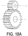
FIG. 18A is a schematic perspective view illustrating a configuration of a spur gear. -
FIG. 18B is a view illustrating a machined pattern formed so as to intersect with the meshing advancing direction of the spur gear. - Hereinafter, some embodiments of the present disclosure will be described with reference to the accompanying drawings. However, dimensions, materials, shapes, relative arrangements, or the like of components described in the embodiments or illustrated in the drawings are not intended to limit the scope of the present invention thereto, and are merely illustrative examples.
- For instance, an expression of relative or absolute arrangement such as "in a direction", "along a direction", "parallel", "orthogonal", "centered", "concentric" or "coaxial" shall not be construed as indicating only the arrangement in a strict literal sense, but also includes a state where the arrangement is relatively displaced by a tolerance, or by an angle or a distance within a range where the same function can be achieved.
- For instance, an expression of an equal state such as "same", "equal", "uniform" or the like shall not be construed as indicating only the state in which the feature is strictly equal, but also includes a state in which there is a tolerance or a difference within a range where the same function can be achieved.
- Further, for example, an expression of a shape such as a rectangular shape, a cylindrical shape or the like shall not be construed as only the geometrically strict shape, but also includes a shape with unevenness, chamfered corners or the like within the range where the same effect can be achieved.
- On the other hand, an expression such as "provided", "comprise", "contain", "include", or "have" are not intended to be exclusive of other components.
-
FIG. 1 is a block diagram illustrating a schematic hardware configuration of a tooth surface shapedesign support device 2 according to an embodiment.FIG. 2 is a block diagram illustrating a functional schematic configuration of the tooth surface shapedesign support device 2 illustrated inFIG. 1 . The tooth surface shapedesign support device 2 is used to support the design of the tooth surface shape of a gear. - As illustrated in
FIG. 1 , the tooth surface shapedesign support device 2 includes a central processing unit (CPU) 72, a random access memory (RAM) 74, a read only memory (ROM) 76, a hard disk drive (HDD) 78, an input I/F 80, and an output I/F 82, and is configured using a computer in which these components are connected to each other via abus 84. The hardware configuration of the tooth surface shapedesign support device 2 is not limited to the above, and may be configured by a combination of a control circuit and a storage device. The tooth surface shapedesign support device 2 is configured by a computer executing a program (tooth surface shape design support program) that realizes each function of the tooth surface shapedesign support device 2. The function of each unit in the tooth surface shapedesign support device 2 described below is realized by, for example, loading a program held in aROM 76 into theRAM 74 and executing the program by theCPU 72, and reading and writing data in theRAM 74 and theROM 76. - As illustrated in
FIG. 2 , the tooth surface shapedesign support device 2 includes a sample data generation unit 4, the principal component shapedata acquisition unit 6, a tooth surfaceshape evaluation unit 8, and the tooth surfaceshape determination unit 10. The functions of each component illustrated inFIG. 2 will be described below. -
FIG. 3 is a diagram illustrating a processing flow for evaluating a tooth surface shape of a gear. - In S11 of
FIG. 3 , the sample data generation unit 4 generates the tooth surface shape sample data group Dg as illustrated inFIG. 4 using at least one tooth surface modification parameter based on general tooth surface design guidelines (low stress design and low vibration force design). The tooth surface shape sample data group Dg illustrated inFIG. 4 includes tooth surface shape sample data D1 to D15 indicating samples of tooth surface shape, and each of the tooth surface shape sample data D1 to D15 indicates a three-dimensional shape of a tooth surface. When the position in the tooth width direction (X direction) is defined as Xi, the position in the tooth height direction (Y direction) is defined as Yj, and the position in the direction orthogonal to each of the tooth width direction and the tooth height direction (Z Direction) is defined as Zi,j, the tooth surface shape sample data group Dg is, for example, as illustrated inFIG. 5 , point sequence data (matrix data) showing the Z coordinate Zi,j of the tooth surface in each position coordinate (Xi,Yj) for each of the tooth surface shape sample data D1 to D15. Here, when the number of data in the tooth width direction in each of the tooth surface shape sample data D1 to D15 is defined as w and the number of data in the tooth height direction is defined as h, i is an integer from 1 to w and j is an integer from 1 to h. - The at least one tooth surface modification parameter includes, for example, at least one of a tooth profile modification, a tooth trace modification, a bias modification, a pressure angle modification, and a helix angle modification. The tooth profile modification includes, for example, at least one of a tooth tip modification and a tooth root modification, and the tooth trace modification includes, for example, at least one of crowning and end relief. In addition, the low stress design includes a design in which the tooth tip, the tooth root, and the end portion of the tooth trace are modified so as not to come into contact with each other, and the amount of modification substantially matches the amount of warping of the tooth. In addition, the low vibration force design includes a design in which the modification is performed such that rigidity variation caused by the change in the number of engaged teeth is canceled.
- Next, in the S12 of
FIG. 3 , the principal component shapedata acquisition unit 6 performs principal component analysis (eigenvalue orthogonal analysis) on the tooth surface shape sample data group Dg. Then, in the S13, the principal component shapedata acquisition unit 6 extracts and acquires a plurality of principal component shape data uk from the result of the principal component analysis on the tooth surface shape sample data group Dg. -
FIG. 6 illustrates an example of a plurality of principal component shape data uk acquired by the principal component shapedata acquisition unit 6. Here, k is the order of the principal component shape, and in the example illustrated inFIG. 6 , k is an integer from 1 to 6. In the illustrated example, first-order principal component shape data u1, second-order principal component shape data u2, third-order principal component shape data u3, fourth-order principal component shape data u4, fifth-order principal component shape data u5, and sixth-order principal component shape data u6 are illustrated, which are extracted from the result of the principal component analysis on the tooth surface shape sample data group Dg. As illustrated inFIG. 7 , each of the principal component shape data u1 to u6 is point sequence data (matrix data) indicating the position Zi,j of the tooth surface at each position coordinate (Xi,Yj). Here, when the number of data in the tooth width direction in each of the principal component shape data u1 to u6 is defined as w and the number of data in the tooth height direction is defined as h, i is an integer from 1 to w and j is an integer from 1 to h. - Next, in the S14, the tooth surface
shape evaluation unit 8 evaluates the tooth surface shape Φ defined using a linear combination of the plurality of principal component shape data uk acquired by the principal component shapedata acquisition unit 6. Here, the tooth surfaceshape evaluation unit 8 defines the tooth surface shape Φ by the following Equation (a).
- Here, v is average shape of the tooth surface shape indicated by each of the tooth surface shape sample data D1 to D15, αk is a linear combination coefficient of the principal component shape data uk, and n is the maximum order (6 in the above example) of the principal component shape data extracted from the result of the principal component analysis.
- In the S14, the tooth surface
shape evaluation unit 8 performs gear analysis on the gear having the tooth surface shape Φ, and evaluates the tooth surface shape Φ by evaluating stress (e.g., surface pressure and tooth root stress) and vibration force generated in the gear. Here, the tooth surfaceshape evaluation unit 8 evaluates a plurality of tooth surface shapes Φ obtained by changing the linear combination coefficient αk. - In the S15, the tooth surface
shape determination unit 10 determines an optimum tooth surface shape (e.g., seeFIG. 8 ) that can achieve both low stress and low vibration force based on the result (result of parameter study with linear combination coefficient αk as parameter) of evaluation by the tooth surfaceshape evaluation unit 8 on the plurality of tooth surface shapes Φ obtained by changing the linear combination coefficient αk. Thus, an optimum tooth surface shape capable of achieving both improvement in load capacity and improvement in quietness is determined. When the number of analyses is enormous, the tooth surfaceshape evaluation unit 8 and the tooth surfaceshape determination unit 10 may appropriately use an optimization method such as a Monte Carlo method. -
FIG. 9 is a block diagram illustrating a modified example of the tooth surface shapedesign support device 2 described with reference toFIG. 2 or the like. The tooth surface shapedesign support device 2 illustrated inFIG. 9 is different from the tooth surface shapedesign support device 2 illustrated inFIG. 2 in that the tooth surface shapedesign support device 2 illustrated inFIG. 9 includes a symmetrical tooth surfaceshape generation unit 12. For each configuration of the tooth surface shapedesign support device 2 illustrated inFIG. 9 , the same reference sign as that of each configuration of the tooth surface shapedesign support device 2 illustrated inFIG. 2 or the like indicate the same configuration as that of each configuration of the tooth surface shapedesign support device 2 illustrated inFIG. 2 or the like unless otherwise specified, and description thereof will be omitted. - The symmetrical tooth surface
shape generation unit 12 generates a plurality of tooth surface shape data Δk having symmetrical shapes based on each of the plurality of principal component shape data uk acquired by the principal component shapedata acquisition unit 6. Hereinafter, the principal component shape indicated by the principal component shape data uk is also referred to as a principal component shape uk for convenience. - For each of the principal component shape data uk acquired by the principal component shape
data acquisition unit 6, as expressed in the following Equation (b1), the symmetrical tooth surfaceshape generation unit 12 generates tooth surface shape data Δ1_i,j having a symmetrical shape by averaging Z coordinates at symmetrical positions in the tooth surface with the central position M1 (seeFIG. 10 ) of the tooth surface in the tooth height direction as an axis of symmetry.
- Here, as illustrated in
FIG. 11 , when the number of data in the tooth width direction in each of the principal component shape data uk is defined as w and the number of data in the tooth height direction is defined as h, i is an integer from 1 to w and j is an integer from 1 to h. Further, Zi,j is the Z coordinate of the principal component shape uk at a position (Xi,Yj), and Zi,(h- j + 1) is the Z coordinate of the principal component shape uk at a position (Xi, Y(h -j+1)) symmetrical to the position (Xi,Yj) with the central position M1 as an axis of symmetry. - For each of the principal component shape data uk acquired by the principal component shape
data acquisition unit 6, as expressed in the following Equation (b2), the symmetrical tooth surfaceshape generation unit 12 generates tooth surface shape data Δ2_i,j having a symmetrical shape by averaging Z coordinates at symmetrical positions in the tooth surface with the central position M2 (seeFIG. 12 ) of the tooth surface in the tooth width direction as an axis of symmetry.
- Here, Z(w - i + 1),j is the Z coordinate of the principal component shape uk at the symmetrical position (X(w - i + 1), Yj) of the position (Xi,Yj) with the central position M2 as the axis of symmetry.
- For each of the principal component shape data uk acquired by the principal component shape
data acquisition unit 6, as expressed in the following Equation (b3), the symmetrical tooth surfaceshape generation unit 12 generates tooth surface shape data Δ3_i,j having a symmetrical shape by averaging Z coordinates at symmetrical positions in the tooth surface with a diagonal M3 (seeFIG. 13 ) intersecting each of the tooth width direction and the tooth height direction of the tooth surface as an axis of symmetry.
- Here, Zj,i is the Z coordinate of the principal component shape uk at the symmetrical position (Xj, Yi) of the position (Xi, Yj) with the diagonal M3 as an axis of symmetry.
- Additionally, for each of the principal component shape data uk acquired by the principal component shape
data acquisition unit 6, as expressed in the following Equation (b4), the symmetrical tooth surfaceshape generation unit 12 generates tooth surface shape data Δ4_i,j having a symmetrical shape by averaging Z coordinates at symmetrical positions in the tooth surface with a diagonal M4 (not illustrated) intersecting each of the tooth width direction and the tooth height direction of the tooth surface as an axis of symmetry.
- Here, Z(w - i + 1),(h - j + 1) is the Z coordinate of the principal component shape uk at the symmetrical position (Y(w - i + 1),X(h - j + 1)) of the position (Xi,Yj) with the diagonal M4 as an axis of symmetry.
- From among the central positions M1 and M2, and diagonals M3 and M4, the symmetrical tooth surface
shape generation unit 12 selects the axis of symmetry having the smallest sum of differences between the principal component shape uk and each of the symmetrical shapes Δ1_i, j to Δ4_i,j as expressed in the following Equation (c). Then, data Δi,j of a tooth surface shape having a symmetrical shape using the selected axis of symmetry are determined.
- Then, the tooth surface
shape evaluation unit 8 evaluates the tooth surface shape Φ defined by the following Equation (d) using the linear combination of the tooth surface shape data Δi,j having the symmetrical shape determined by the symmetrical tooth surfaceshape generation unit 12.
- Here, v is the average shape of the tooth surface shapes indicated by each of the tooth surface shape sample data D1 to D15, Δk is the tooth surface shape data Δi,j having the symmetrical shape determined using the principal component shape uk, βk is the linear combination coefficient of the tooth surface shape data Δk having the symmetrical shape, and n is the maximum order (6 in the above example) of the principal component shape data extracted from the result of the principal component analysis.
- The tooth surface
shape evaluation unit 8 performs gear analysis on the gear having the tooth surface shape Φ, and evaluates the tooth surface shape Φ by stress (e.g., surface pressure and tooth root stress) and vibration force generated in the gear. Here, the tooth surfaceshape evaluation unit 8 evaluates a plurality of tooth surface shapes Φ obtained by changing the linear combination coefficient of the tooth surface shape data Δi,j. - The tooth surface
shape determination unit 10 determines an optimum tooth surface shape capable of achieving both low stress and low vibration force based on the evaluation result by the tooth surfaceshape evaluation unit 8 with respect to a plurality of tooth surface shapes Φ obtained by changing the linear combination coefficient of the tooth surface shape data Δi,j. - In the embodiment illustrated in
FIGS. 9 to 13 , since the gear analysis is performed using the principal component shape in which the discontinuity of the point sequence data is reduced by performing the averaging process for generating the symmetrical shape, the discontinuity of the point sequence data is reduced in the generated optimum tooth surface shape, and the generated optimum tooth surface shape becomes a smooth curved surface as compared with the embodiment illustrated inFIG. 2 or the like. Therefore, processing management and accuracy management are facilitated. - Further, since the gear analysis is performed using the principal component shape obtained by symmetrically shaping and simplifying the shape, even when the generated optimum tooth surface shape is represented in a drawing by a modified shape represented by several lines in the tooth width direction (e.g., modified shapes at the positions A1, A2, and A3 in the tooth height direction as illustrated in
FIGS. 14A and14B ) or by a modified shape represented by several lines in the tooth height direction (e.g., modified shapes at the positions B1, B2, and B3 in the tooth width direction as illustrated inFIGS. 15A and15B ), the difference from the optimum tooth surface shape becomes small because the section between the indicated shape data is subjected to spline interpolation or the like during machining. Therefore, it becomes easy to describe in the drawings, instruct the manufacturing department or supplier, and manage the machining accuracy. -
FIG. 16 is a block diagram illustrating a schematic configuration of thegear machining system 20 to which the tooth surface shapedesign support device 2 illustrated inFIG. 2 orFIG. 9 can be applied. Agear machining system 20 illustrated inFIG. 16 includes a tooth surface shapedesign support device 2, agear machining machine 22, and agear measuring machine 24. - The
gear machining machine 22 is configured to machine the tooth surface of the gear based on the optimum tooth surface shape determined by the tooth surface shapedesign support device 2. - The
gear measuring machine 24 measures the actual tooth surface shape of the gear (workpiece) machined by thegear machining machine 22, and transmits measurement data of the tooth surface shape to the tooth surface shapedesign support device 2. The tooth surface shapedesign support device 2 analyzes the surface pressure, the tooth root stress, and the vibration force reflecting the measured actual tooth surface shape, and uses them for designing the tooth surface shape. Further, thegear machining machine 22 can reduce the machining error by performing the tooth surface correction and the dimension correction of the gear based on the measurement data of the tooth surface shape measured by thegear measuring machine 24. - In some embodiments, the
gear machining machine 22 illustrated inFIG. 16 may be a five-axis machining machine. Thus, even when the tooth surface shape determined by the tooth surface shapedesign support device 2 is a complicated shape, the tooth surface shape can be accurately realized. - Further, in this case, the
gear machining machine 22 is preferably configured to machine the tooth surface such that the machined pattern intersects with the meshing advancing direction of the gear, and more preferably configured to machine the tooth surface such that the machined pattern is orthogonal to the meshing advancing direction of the gear. That is, the tool path (the path along which the tool moves when machining is performed) of thegear machining machine 22 is preferably set so as to intersect with the meshing advancing direction of the gear, and more preferably set so as to be orthogonal to the meshing advancing direction of the gear. - Therefore, for example, for a spur gear as illustrated in
FIG. 18A , it is desirable that thegear machining machine 22 machines the tooth surface so that a machined pattern is formed along the axial direction as illustrated inFIG. 18B . In addition, for example, for a helical gear as illustrated inFIG. 17A , it is preferable that thegear machining machine 22 machines the tooth surface so that a machined pattern is formed along an oblique direction intersecting each of the axial direction and the radial direction as illustrated inFIG. 17B . In the case of a helical gear, the angle of the meshing advancing direction changes depending on the helix angle of the helical gear. - In this way, by causing the machined pattern to intersect with the meshing advancing direction of the gear, it is possible to expect an increase in the thickness of the oil film on the tooth surface as compared with the case where the machined pattern is formed in parallel with the meshing advancing direction of the gear, and it is possible to expect an improvement in load capacity (durability) due to an increase in support load (decrease in solid contact load) through the oil film. Therefore, it is possible to achieve both an improvement in load capacity and an improvement in quietness.
- The present disclosure is not limited to the above-described embodiments, and includes embodiments obtained by modifying the above-described embodiments and embodiments obtained by appropriately combining these embodiments.
- For example, in the embodiment illustrated in
FIG. 9 or the like, the symmetrical tooth surfaceshape generation unit 12 has selected, from among the central positions M1 and M2, and diagonals M3 and M4, the axis of symmetry having the smallest sum of differences between the principal component shape uk and each of the symmetrical shapes Δ1_i,j to Δ4_i,j, and then, tooth surface shape data Δi,j having a symmetrical shape using the selected axis of symmetry have been determined. However, the symmetrical tooth surfaceshape generation unit 12 can generate a plurality of tooth surface shape data Δi,j having a symmetrical shape by averaging the Z coordinates at symmetrical positions in the tooth surface, with at least one of the central positions M1 and M2, and the diagonals M3 and M4 as an axis of symmetry for each of the principal component shape data uk. For example, the symmetrical tooth surfaceshape generation unit 12 may generate only one of the symmetrical shapes Δ1_i,j to Δ4_i,j as the tooth surface shape data Δi,j having the symmetrical shape, and the tooth surfaceshape evaluation unit 8 may evaluate the data Δi,j. - In some embodiments described above, the principal component analysis on the tooth surface shape sample data group Dg is performed by the principal component shape
data acquisition unit 6, but the principal component analysis on the tooth surface shape sample data group Dg may be performed outside the tooth surface shapedesign support device 2. That is, principal component analysis may be performed on the tooth surface shape sample data group Dg outside the tooth surface shapedesign support device 2, and the principal component shapedata acquisition unit 6 may acquire the principal component shape data uk extracted from the result of the principal component analysis. - The content described in each of the above embodiments is understood as follows, for example.
- (1) A tooth surface shape design support device (e.g., the above-described tooth surface shape design support device 2) according to at least one embodiment of the present disclosure is a tooth surface shape design support device for supporting design of a tooth surface shape of a gear, including a principal component shape data acquisition unit (e.g., the above-described principal component shape data acquisition unit 6) configured to acquire a plurality of principal component shape data obtained by performing principal component analysis on a tooth surface shape sample data group including a plurality of tooth surface shape sample data indicating samples of the tooth surface shape, and a tooth surface shape evaluation unit (e.g., the above-described tooth surface shape evaluation unit 8) configured to evaluate a tooth surface shape defined by using the plurality of principal component shape data acquired by the principal component shape data acquisition unit.
According to the tooth surface shape design support device described in the above (1), as compared with the case where the tooth surface shape is evaluated by using all the coordinates of the tooth surface shape as parameters, by evaluating the tooth surface shape defined by using a plurality of principal component shape data obtained by principal component analysis for a tooth surface shape sample data group, it is possible to efficiently evaluate a complicated tooth surface shape with a small amount of calculation. Thus, for example, it is possible to effectively support the design of a complicated tooth surface shape so as to achieve both improvement in load capacity and improvement in quietness of the gear with a small amount of calculation. - (2) In some embodiments, in the tooth surface shape design support device according to the above (1), the tooth surface shape evaluation unit is configured to evaluate stress and vibration force generated in the gear.
According to the tooth surface shape design support device described in the above (2), it is possible to efficiently evaluate stress and vibration force generated in a gear having a complicated tooth surface shape with a small amount of calculation. Thus, it is possible to effectively support the design of a complicated tooth surface shape so as to achieve both improvement in load capacity and improvement in quietness of the gear with a small amount of calculation. - (3) In some embodiments, the tooth surface shape design support device according to the above (1) or (2) further includes, a sample data generation unit (e.g., the above-described sample data generation unit 4) configured to generate the tooth surface shape sample data group by using at least one tooth surface modification parameter among tooth profile modification, tooth trace modification, bias modification, pressure angle modification, and helix angle modification.
According to the tooth surface shape design support device described in the above (3), since the principal component shape data acquired from the tooth surface shape sample data group generated using at least one tooth surface modification parameter can be evaluated, a complicated tooth surface shape can be efficiently evaluated with a small amount of calculation. Thus, for example, it is possible to effectively support the design of a complicated tooth surface shape so as to achieve both improvement in load capacity and improvement in quietness of the gear with a small amount of calculation. - (4) In some embodiments, in the tooth surface shape design support device according to any one of the above (1) to (3), the tooth surface shape evaluation unit is configured to define the tooth surface shape by using a linear combination of the plurality of principal component shape data acquired by the principal component shape data acquisition unit, and to evaluate a plurality of tooth surface shapes obtained by changing a coefficient of the linear combination.
According to the tooth surface shape design support device described in the above (4), a complicated tooth surface shape can be efficiently defined and efficiently evaluated with a small amount of calculation. - (5) In some embodiments, the tooth surface shape design support device according to any one of the above (1) to (3) further includes, a symmetrical tooth surface shape generation unit (e.g., the symmetrical tooth surface
shape generation unit 12 described above) configured to generate a plurality of tooth surface shape data having symmetrical shapes based on each of the plurality of principal component shape data acquired by the principal component shape data acquisition unit, and the tooth surface shape evaluation unit is configured to define the tooth surface shape by using a linear combination of the plurality of tooth surface shape data having the symmetrical shapes generated by the symmetrical tooth surface shape generation unit, and to evaluate a plurality of tooth surface shapes obtained by changing coefficients of the linear combination.
According to the tooth surface shape design support device described in the above (5), a complicated tooth surface shape can be efficiently defined and evaluated with a small amount of calculation. - (6) In some embodiments, in the tooth surface shape design support device according to the above (5), when a position in a direction orthogonal to each of the tooth width direction and the tooth height direction is defined as a Z coordinate, the symmetrical tooth surface shape generation unit is configured to generate a plurality of tooth surface shape data having the symmetrical shape by averaging Z coordinates at symmetrical positions in the tooth surface, with at least one of a central position of the tooth surface in the tooth width direction, a central position of the tooth surface in the tooth height direction, and a diagonal of the tooth surface as an axis of symmetry, for each of the plurality of principal component shape data acquired by the principal component shape data acquisition unit.
According to the tooth surface shape design support device described in the above (6), since the tooth surface shape defined by using the principal component shape data is evaluated with respect to the principal component shape data in which the discontinuity of the point sequence data is reduced by performing the averaging process, it is possible to evaluate the tooth surface shape of the smooth curved surface. Therefore, it is possible to design a tooth surface shape having a smooth curved surface with small discontinuity of the point sequence data, and it is easy to perform processing management and accuracy management. - (7) In some embodiments, the tooth surface shape design support device according to any one of the above (1) to (6) further includes a tooth surface shape determination unit (e.g., the tooth surface
shape determination unit 10 described above) configured to determine the tooth surface shape of the gear based on an evaluation result of the tooth surface shape evaluation unit.
According to the tooth surface shape design support device described in the above (7), it is possible to efficiently determine a complicated tooth surface shape with a small amount of calculation. Thus, for example, it is possible to effectively support the design of a complicated tooth surface shape so as to achieve both improvement in load capacity and improvement in quietness of the gear with a small amount of calculation. - (8) A gear machining system (e.g., the above-described gear machining system 20) according to at least one embodiment of the present disclosure includes, the tooth surface shape design support device according to the above (7), and a gear machining machine (e.g., the above-described gear machining machine 22) that machines a tooth surface of a gear based on the tooth surface shape determined by the tooth surface shape design support device.
According to the gear machining system described in the above (8), it is possible to manufacture a gear excellent in load capacity and quietness. - (9) In some embodiments, in the gear machining system according to the above (8), the gear machining machine is configured to machine the tooth surface such that a machined pattern intersects with a meshing advancing direction of the gear.
According to the gear machining system described in the above (9), by causing the machined pattern to intersect with the meshing advancing direction of the gear, it is possible to expect an increase in the thickness of the oil film on the tooth surface as compared with the case where the machined pattern is formed in parallel with the meshing advancing direction of the gear. Therefore, it is expected that the load capacity (durability) will be improved due to an increase of the support load through the oil film (a decrease of the solid contact load). Therefore, it is possible to achieve both an improvement in load capacity and an improvement in quietness. - (10) A tooth surface shape design support program according to at least one embodiment of the present disclosure is a tooth surface shape design support program for supporting design of a tooth surface shape of a gear, the program causing a computer to execute the steps of, acquiring a plurality of principal component shape data obtained by performing principal component analysis on a tooth surface shape sample data group including a plurality of tooth surface shape sample data indicating samples of the tooth surface shape, and evaluating the tooth surface shape defined by using the plurality of principal component shape data.
- According to the tooth surface shape design support program described in the above (10), as compared with the case where the tooth surface shape is evaluated by using all the coordinates of the tooth surface shape as parameters, the tooth surface shape defined by using the plurality of principal component shape data obtained by the principal component analysis with respect to the tooth surface shape sample data group is evaluated and thus it is possible to efficiently evaluate the complicated tooth surface shape with a small amount of calculation. Thus, for example, it is possible to effectively support the design of a complicated tooth surface shape so as to achieve both improvement in load capacity and improvement in quietness of the gear with a small amount of calculation.
-
- 2 Tooth surface shape design support device
- 4 Sample data generation unit
- 6 Principal component shape data acquisition unit
- 8 Tooth surface shape evaluation unit
- 10 Tooth surface shape determination unit
- 12 Symmetrical tooth surface shape generation unit
- 20 Gear machining system
- 22 Gear machining machine
- 24 Gear measuring machine
- 72 CPU
- 74 RAM
- 76 ROM
- 78 HDD
- 80 Input I/F
- 82 Output I/F
- 84 Bus
Claims (10)
- A tooth surface shape design support device for supporting design of a tooth surface shape of a gear, comprising:a principal component shape data acquisition unit configured to acquire a plurality of principal component shape data obtained by performing principal component analysis on a tooth surface shape sample data group including a plurality of tooth surface shape sample data indicating samples of the tooth surface shape; anda tooth surface shape evaluation unit configured to evaluate a tooth surface shape defined by using the plurality of principal component shape data acquired by the principal component shape data acquisition unit.
- The tooth surface shape design support device according to claim 1, wherein the tooth surface shape evaluation unit is configured to evaluate stress and vibration force generated in the gear.
- The tooth surface shape design support device according to claim 1 or 2, further comprising:
a sample data generation unit configured to generate the tooth surface shape sample data group by using at least one tooth surface modification parameter among tooth profile modification, tooth trace modification, bias modification, pressure angle modification, and helix angle modification. - The tooth surface shape design support device according to any one of claims 1 to 3, wherein the tooth surface shape evaluation unit is configured to define the tooth surface shape by using a linear combination of the plurality of principal component shape data acquired by the principal component shape data acquisition unit, and to evaluate a plurality of tooth surface shapes obtained by changing a coefficient of the linear combination.
- The tooth surface shape design support device according to any one of claims 1 to 3, further comprising:a symmetrical tooth surface shape generation unit configured to generate a plurality of tooth surface shape data having symmetrical shapes based on each of the plurality of principal component shape data acquired by the principal component shape data acquisition unit, whereinthe tooth surface shape evaluation unit is configured to define the tooth surface shape by using a linear combination of the plurality of tooth surface shape data having the symmetrical shapes generated by the symmetrical tooth surface shape generation unit, and to evaluate a plurality of tooth surface shapes obtained by changing a coefficient of the linear combination.
- The tooth surface shape design support device according to claim 5, wherein
when a position in a direction orthogonal to each of a tooth width direction and a tooth height direction is defined as a Z coordinate,
the symmetrical tooth surface shape generation unit generates a plurality of tooth surface shape data having the symmetrical shape by averaging Z coordinates at symmetrical positions in the tooth surface, with at least one of a central position of the tooth surface in the tooth width direction, a central position of the tooth surface in the tooth height direction, and a diagonal of the tooth surface as an axis of symmetry, for each of the plurality of principal component shape data acquired by the principal component shape data acquisition unit. - The tooth surface shape design support device according to any one of claims 1 to 6, further comprising:
a tooth surface shape determination unit configured to determine the tooth surface shape of the gear based on an evaluation result of the tooth surface shape evaluation unit. - A gear machining system, comprising:the tooth surface shape design support device according to claim 7; anda gear machining machine that machines a tooth surface of a gear based on the tooth surface shape determined by the tooth surface shape design support device.
- The gear machining system according to claim 8, wherein the gear machining machine is configured to machine the tooth surface such that a machined pattern intersects with a meshing advancing direction of the gear.
- A tooth surface shape design support program for supporting design of a tooth surface shape of a gear, the program causing a computer to execute the steps of:acquiring a plurality of principal component shape data obtained by performing principal component analysis on a tooth surface shape sample data group including a plurality of tooth surface shape sample data indicating samples of the tooth surface shape; andevaluating the tooth surface shape defined by using the plurality of principal component shape data.
Applications Claiming Priority (1)
| Application Number | Priority Date | Filing Date | Title |
|---|---|---|---|
| JP2020093065A JP2021189639A (en) | 2020-05-28 | 2020-05-28 | Tooth surface shape design support device, gear processing system, and gear shape design support program |
Publications (1)
| Publication Number | Publication Date |
|---|---|
| EP3916267A1 true EP3916267A1 (en) | 2021-12-01 |
Family
ID=75825507
Family Applications (1)
| Application Number | Title | Priority Date | Filing Date |
|---|---|---|---|
| EP21172235.0A Withdrawn EP3916267A1 (en) | 2020-05-28 | 2021-05-05 | Tooth surface shape design support device, gear machining system, and tooth surface shape design support program |
Country Status (3)
| Country | Link |
|---|---|
| US (1) | US20210374303A1 (en) |
| EP (1) | EP3916267A1 (en) |
| JP (1) | JP2021189639A (en) |
Cited By (1)
| Publication number | Priority date | Publication date | Assignee | Title |
|---|---|---|---|---|
| EP4541493A1 (en) * | 2023-10-20 | 2025-04-23 | Volvo Car Corporation | Helical gear and machining method thereof |
Families Citing this family (2)
| Publication number | Priority date | Publication date | Assignee | Title |
|---|---|---|---|---|
| CN115186414B (en) * | 2022-08-05 | 2025-07-11 | 福州大学 | A tooth surface modification design method for improving the transmission load-bearing capacity of aviation face gears |
| IT202200017307A1 (en) * | 2022-08-12 | 2024-02-12 | Gen Electric | TRANSMISSION GROUP |
Citations (2)
| Publication number | Priority date | Publication date | Assignee | Title |
|---|---|---|---|---|
| JP2006242211A (en) | 2005-02-28 | 2006-09-14 | Mitsubishi Heavy Ind Ltd | Transmission gear and its manufacturing method |
| JP2010164134A (en) * | 2009-01-15 | 2010-07-29 | Fuji Heavy Ind Ltd | Apparatus, program and method for designing gear pair and gear pair |
Family Cites Families (1)
| Publication number | Priority date | Publication date | Assignee | Title |
|---|---|---|---|---|
| CN112191949B (en) * | 2019-07-08 | 2024-09-13 | 株式会社捷太格特 | Gear machining auxiliary device and gear machining device |
-
2020
- 2020-05-28 JP JP2020093065A patent/JP2021189639A/en active Pending
-
2021
- 2021-03-31 US US17/218,497 patent/US20210374303A1/en not_active Abandoned
- 2021-05-05 EP EP21172235.0A patent/EP3916267A1/en not_active Withdrawn
Patent Citations (2)
| Publication number | Priority date | Publication date | Assignee | Title |
|---|---|---|---|---|
| JP2006242211A (en) | 2005-02-28 | 2006-09-14 | Mitsubishi Heavy Ind Ltd | Transmission gear and its manufacturing method |
| JP2010164134A (en) * | 2009-01-15 | 2010-07-29 | Fuji Heavy Ind Ltd | Apparatus, program and method for designing gear pair and gear pair |
Non-Patent Citations (2)
| Title |
|---|
| SHAO NAN ET AL: "Tolerance analysis of spur gears based on skin model shapes and a boundary element method", MECHANISM AND MACHINE THEORY, PERGAMON, AMSTERDAM, NL, vol. 144, 23 October 2019 (2019-10-23), XP085905676, ISSN: 0094-114X, [retrieved on 20191023], DOI: 10.1016/J.MECHMACHTHEORY.2019.103658 * |
| XU YUDONG ET AL: "Application of principal component analysis and BP neural network in gear noise prediction", COMPUTER ENGINEERING AND TECHNOLOGY (ICCET), 2010 2ND INTERNATIONAL CONFERENCE ON, IEEE, PISCATAWAY, NJ, USA, 16 April 2010 (2010-04-16), pages V5 - 251, XP031690213, ISBN: 978-1-4244-6347-3 * |
Cited By (1)
| Publication number | Priority date | Publication date | Assignee | Title |
|---|---|---|---|---|
| EP4541493A1 (en) * | 2023-10-20 | 2025-04-23 | Volvo Car Corporation | Helical gear and machining method thereof |
Also Published As
| Publication number | Publication date |
|---|---|
| JP2021189639A (en) | 2021-12-13 |
| US20210374303A1 (en) | 2021-12-02 |
Similar Documents
| Publication | Publication Date | Title |
|---|---|---|
| EP3916267A1 (en) | Tooth surface shape design support device, gear machining system, and tooth surface shape design support program | |
| Samper et al. | Modeling of 2D and 3D assemblies taking into account form errors of plane surfaces | |
| Larue et al. | Deviation of a machined surface in flank milling | |
| US9588014B2 (en) | Error measuring method of gear | |
| EP3521958A1 (en) | Manufacturing assistance apparatus | |
| CN117408096A (en) | Methods, devices, equipment and media for determining meshing stiffness of helical gears | |
| Ramnath et al. | Comparative study of tolerance analysis methods applied to a complex assembly | |
| Gauder et al. | Simulation uncertainty determination of single flank rolling tests using monte carlo simulation and skin model shapes for zero defect manufacturing of micro gears | |
| Wang et al. | Development of a novel type of hybrid non-symmetric flexure hinges | |
| Irsel | Bevel gears strength calculation: Comparison ISO, AGMA, DIN, KISSsoft and ANSYS FEM methods | |
| Zhang et al. | Accurate modeling of threaded connections and evaluation of contact surface distribution errors oriented to accurate digital twins | |
| Gadelmawla | A novel system for automatic measurement and inspection of parallel screw threads | |
| CN113239597B (en) | Gauss numerical bivariate weight function method of stress intensity factor and electronic equipment | |
| Chiesi et al. | Tolerance analysis with eM-TolMate | |
| Pierce et al. | A method for integrating form errors into geometric tolerance analysis | |
| Van Gestel | Determining measurement uncertainties of feature measurements on CMMs | |
| WO2013108855A1 (en) | Wire harness analysis device, wire harness analysis method, and wire harness analysis program | |
| Meirbek et al. | Current issues in uncertainty of dimensional tolerance metrology and the future development in the domain of tolerancing | |
| US11198204B2 (en) | Tool path generation method | |
| Haefner et al. | Finite element simulation for quality dependent lifetime analysis of micro gears | |
| JP3008764B2 (en) | Spline manufacturing target dimension control method | |
| JP4484111B2 (en) | Evaluation Method for Gear Tooth Surface Profile Measuring Machine | |
| EP4305498B1 (en) | Method for generating a virtual geometry, and system for data processing | |
| CN113239570B (en) | Gaussian numerical univariate weight function method of stress intensity factor and electronic equipment | |
| Komori et al. | Artifact design and measurement error analysis in the evaluation of lead measurement accuracy of helical gear using wedge artifact |
Legal Events
| Date | Code | Title | Description |
|---|---|---|---|
| PUAI | Public reference made under article 153(3) epc to a published international application that has entered the european phase |
Free format text: ORIGINAL CODE: 0009012 |
|
| STAA | Information on the status of an ep patent application or granted ep patent |
Free format text: STATUS: THE APPLICATION HAS BEEN PUBLISHED |
|
| AK | Designated contracting states |
Kind code of ref document: A1 Designated state(s): AL AT BE BG CH CY CZ DE DK EE ES FI FR GB GR HR HU IE IS IT LI LT LU LV MC MK MT NL NO PL PT RO RS SE SI SK SM TR |
|
| B565 | Issuance of search results under rule 164(2) epc |
Effective date: 20211103 |
|
| STAA | Information on the status of an ep patent application or granted ep patent |
Free format text: STATUS: REQUEST FOR EXAMINATION WAS MADE |
|
| 17P | Request for examination filed |
Effective date: 20220317 |
|
| RBV | Designated contracting states (corrected) |
Designated state(s): AL AT BE BG CH CY CZ DE DK EE ES FI FR GB GR HR HU IE IS IT LI LT LU LV MC MK MT NL NO PL PT RO RS SE SI SK SM TR |
|
| GRAP | Despatch of communication of intention to grant a patent |
Free format text: ORIGINAL CODE: EPIDOSNIGR1 |
|
| STAA | Information on the status of an ep patent application or granted ep patent |
Free format text: STATUS: GRANT OF PATENT IS INTENDED |
|
| RIC1 | Information provided on ipc code assigned before grant |
Ipc: G06F 30/20 20200101ALI20230328BHEP Ipc: G01M 13/028 20190101ALI20230328BHEP Ipc: G01M 13/021 20190101ALI20230328BHEP Ipc: F16H 57/00 20120101ALI20230328BHEP Ipc: G06F 30/17 20200101ALI20230328BHEP Ipc: F16H 55/08 20060101AFI20230328BHEP |
|
| INTG | Intention to grant announced |
Effective date: 20230417 |
|
| STAA | Information on the status of an ep patent application or granted ep patent |
Free format text: STATUS: THE APPLICATION IS DEEMED TO BE WITHDRAWN |
|
| 18D | Application deemed to be withdrawn |
Effective date: 20230829 |