EP3916234B1 - Outgoing line adapter module for pump - Google Patents
Outgoing line adapter module for pump Download PDFInfo
- Publication number
- EP3916234B1 EP3916234B1 EP21175576.4A EP21175576A EP3916234B1 EP 3916234 B1 EP3916234 B1 EP 3916234B1 EP 21175576 A EP21175576 A EP 21175576A EP 3916234 B1 EP3916234 B1 EP 3916234B1
- Authority
- EP
- European Patent Office
- Prior art keywords
- connecting part
- pump
- outgoing line
- module
- line adapter
- Prior art date
- Legal status (The legal status is an assumption and is not a legal conclusion. Google has not performed a legal analysis and makes no representation as to the accuracy of the status listed.)
- Active
Links
Images


Classifications
-
- H—ELECTRICITY
- H01—ELECTRIC ELEMENTS
- H01R—ELECTRICALLY-CONDUCTIVE CONNECTIONS; STRUCTURAL ASSOCIATIONS OF A PLURALITY OF MUTUALLY-INSULATED ELECTRICAL CONNECTING ELEMENTS; COUPLING DEVICES; CURRENT COLLECTORS
- H01R31/00—Coupling parts supported only by co-operation with counterpart
- H01R31/06—Intermediate parts for linking two coupling parts, e.g. adapter
-
- F—MECHANICAL ENGINEERING; LIGHTING; HEATING; WEAPONS; BLASTING
- F04—POSITIVE - DISPLACEMENT MACHINES FOR LIQUIDS; PUMPS FOR LIQUIDS OR ELASTIC FLUIDS
- F04D—NON-POSITIVE-DISPLACEMENT PUMPS
- F04D13/00—Pumping installations or systems
- F04D13/02—Units comprising pumps and their driving means
- F04D13/06—Units comprising pumps and their driving means the pump being electrically driven
- F04D13/0693—Details or arrangements of the wiring
-
- F—MECHANICAL ENGINEERING; LIGHTING; HEATING; WEAPONS; BLASTING
- F04—POSITIVE - DISPLACEMENT MACHINES FOR LIQUIDS; PUMPS FOR LIQUIDS OR ELASTIC FLUIDS
- F04D—NON-POSITIVE-DISPLACEMENT PUMPS
- F04D29/00—Details, component parts, or accessories
- F04D29/40—Casings; Connections of working fluid
- F04D29/42—Casings; Connections of working fluid for radial or helico-centrifugal pumps
- F04D29/426—Casings; Connections of working fluid for radial or helico-centrifugal pumps especially adapted for liquid pumps
-
- F—MECHANICAL ENGINEERING; LIGHTING; HEATING; WEAPONS; BLASTING
- F04—POSITIVE - DISPLACEMENT MACHINES FOR LIQUIDS; PUMPS FOR LIQUIDS OR ELASTIC FLUIDS
- F04D—NON-POSITIVE-DISPLACEMENT PUMPS
- F04D29/00—Details, component parts, or accessories
- F04D29/60—Mounting; Assembling; Disassembling
- F04D29/62—Mounting; Assembling; Disassembling of radial or helico-centrifugal pumps
- F04D29/628—Mounting; Assembling; Disassembling of radial or helico-centrifugal pumps especially adapted for liquid pumps
-
- H—ELECTRICITY
- H01—ELECTRIC ELEMENTS
- H01R—ELECTRICALLY-CONDUCTIVE CONNECTIONS; STRUCTURAL ASSOCIATIONS OF A PLURALITY OF MUTUALLY-INSULATED ELECTRICAL CONNECTING ELEMENTS; COUPLING DEVICES; CURRENT COLLECTORS
- H01R13/00—Details of coupling devices of the kinds covered by groups H01R12/70 or H01R24/00 - H01R33/00
- H01R13/46—Bases; Cases
- H01R13/502—Bases; Cases composed of different pieces
-
- H—ELECTRICITY
- H01—ELECTRIC ELEMENTS
- H01R—ELECTRICALLY-CONDUCTIVE CONNECTIONS; STRUCTURAL ASSOCIATIONS OF A PLURALITY OF MUTUALLY-INSULATED ELECTRICAL CONNECTING ELEMENTS; COUPLING DEVICES; CURRENT COLLECTORS
- H01R13/00—Details of coupling devices of the kinds covered by groups H01R12/70 or H01R24/00 - H01R33/00
- H01R13/62—Means for facilitating engagement or disengagement of coupling parts or for holding them in engagement
- H01R13/629—Additional means for facilitating engagement or disengagement of coupling parts, e.g. aligning or guiding means, levers, gas pressure electrical locking indicators, manufacturing tolerances
-
- H—ELECTRICITY
- H01—ELECTRIC ELEMENTS
- H01R—ELECTRICALLY-CONDUCTIVE CONNECTIONS; STRUCTURAL ASSOCIATIONS OF A PLURALITY OF MUTUALLY-INSULATED ELECTRICAL CONNECTING ELEMENTS; COUPLING DEVICES; CURRENT COLLECTORS
- H01R13/00—Details of coupling devices of the kinds covered by groups H01R12/70 or H01R24/00 - H01R33/00
- H01R13/648—Protective earth or shield arrangements on coupling devices, e.g. anti-static shielding
- H01R13/652—Protective earth or shield arrangements on coupling devices, e.g. anti-static shielding with earth pin, blade or socket
-
- H—ELECTRICITY
- H01—ELECTRIC ELEMENTS
- H01R—ELECTRICALLY-CONDUCTIVE CONNECTIONS; STRUCTURAL ASSOCIATIONS OF A PLURALITY OF MUTUALLY-INSULATED ELECTRICAL CONNECTING ELEMENTS; COUPLING DEVICES; CURRENT COLLECTORS
- H01R13/00—Details of coupling devices of the kinds covered by groups H01R12/70 or H01R24/00 - H01R33/00
- H01R13/73—Means for mounting coupling parts to apparatus or structures, e.g. to a wall
-
- H—ELECTRICITY
- H02—GENERATION; CONVERSION OR DISTRIBUTION OF ELECTRIC POWER
- H02K—DYNAMO-ELECTRIC MACHINES
- H02K5/00—Casings; Enclosures; Supports
- H02K5/04—Casings or enclosures characterised by the shape, form or construction thereof
- H02K5/22—Auxiliary parts of casings not covered by groups H02K5/06-H02K5/20, e.g. shaped to form connection boxes or terminal boxes
- H02K5/225—Terminal boxes or connection arrangements
-
- H—ELECTRICITY
- H01—ELECTRIC ELEMENTS
- H01R—ELECTRICALLY-CONDUCTIVE CONNECTIONS; STRUCTURAL ASSOCIATIONS OF A PLURALITY OF MUTUALLY-INSULATED ELECTRICAL CONNECTING ELEMENTS; COUPLING DEVICES; CURRENT COLLECTORS
- H01R13/00—Details of coupling devices of the kinds covered by groups H01R12/70 or H01R24/00 - H01R33/00
- H01R13/73—Means for mounting coupling parts to apparatus or structures, e.g. to a wall
- H01R13/74—Means for mounting coupling parts in openings of a panel
- H01R13/748—Means for mounting coupling parts in openings of a panel using one or more screws
Definitions
- the present invention relates to the field of pump technologies, and more particularly, to an outgoing line adapter module for a pump.
- a pump is a machine that conveys fluid or pressurizes the fluid.
- a drive motor is arranged in the pump, and the drive motor is provided with a control box configured to control operation of the drive motor.
- the control box also needs to be provided with an outgoing line adapter interface configured to connect a signal line or a power line extracted from a client.
- the client is configured to transmit a control signal or supply power to the control box to control operation of the drive motor.
- a working environment of the pump is relatively narrow, but an interface size of an existing outgoing line adapter is larger, and thus too much space needs to be taken up. Therefore, in the case of a large number and a large variety of interfaces, difficulty of installation is increased, and it is prone to a problem of pump operation faults caused by insertion of the pins into non-corresponding interfaces, causing the pump cannot adapt to a use environment with strict requirements for space, and further, causing an inefficient mass production of the pump.
- EP3034879A1 describes a pump component with a motor disposed in a stator shell, wherein the stator shell is provided with a terminal box on an axial end side.
- CN 108 331 765 A , JP 2014 143899 A and US 2004/160142 A1 disclose an outgoing line adapter module applied in a pump.
- An objective of the present invention is to provide an outgoing line adapter module for a pump to improve convenience and accuracy in installation of a wiring plug and to improve adaptability to narrow space.
- an outgoing line adapter module according to claim 1 is provided.
- An outgoing line adapter module for a pump includes: a first connecting part and a second connecting part arranged at intervals.
- the first connecting part is detachably installed on an edge of an end part, axially away from a pump body, of a housing of the pump, and the second connecting part is formed in a way that the first connecting part extends outwards in a radial direction of the housing.
- the second connecting part is provided with an integrally-formed adapter member, an end of the adapter member is configured to connect a wiring plug, and another end of the adapter member is configured to connect an electrical contact point on a control module of the pump.
- the first connecting part is provided with a limit member matching with a boss on the housing, the limit member is configured to limit an installation position of the first connecting part on the housing, and the limit member is a recessed part on the first connecting part.
- the first connecting part is provided with a screw hole, and the first connecting part is installed on the housing by screwing a bolt in the screw hole.
- the first connecting part is provided with an integrally-formed earth pin, an earth terminal of the earth pin is fixed to the housing by the bolt, and another terminal of the earth pin is connected to the control module.
- control module is arranged in a control box, and an aperture is provided on a side of the control box close to the adapter member.
- the second connecting part is inserted in the aperture, such that the adapter member is electrically connected to the electrical contact point on the control module.
- the outgoing line adapter module also includes a sealing member configured to seal a gap between the control box and the outgoing line adapter module.
- the adapter member includes a power pin and a signal pin.
- the adapter member includes a power pin, the second connecting part is provided with a through hole, and a signal line is connected to the corresponding electrical contact point on the control module through the through hole.
- first connecting part and the second connecting part are integrally formed, and a reinforcing member is provided between the first connecting part and the second connecting part.
- the present invention has following beneficial effects.
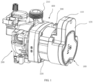
- FIG. 1 is a schematic structural diagram of an integral pump according to an embodiment of the present invention
- a pump 200 is a machine that conveys fluid or pressurizes the fluid.
- the pump 200 includes a pump body 210 and a drive motor (not shown in the figure), and the drive motor (not shown in the figure) may be installed in a housing 220.
- the drive motor (not shown in the figure) is provided with a control box 100 configured to control operation of the drive motor (not shown in the figure).
- the control box 100 includes a box body 110 and a box cover 120, wherein the box cover 120 is covered on the box body 110. Further, the control box 100 may be integrally installed on the housing 220.
- control box 100 also needs to be provided with an outgoing line adapter interface configured to connect a signal line or a power line extracted from a client.
- the client is configured to transmit a control signal or supply power to the control box 100 to control operation of the drive motor.
- An outgoing line adapter module 300 provided by this embodiment may be suitable for optimizing outgoing line adapter control of the control box 100.
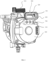
- FIG. 2 is a schematic structural diagram of a pump equipped with the outgoing line adapter module according to an embodiment of the present invention.
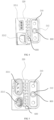
- FIG. 3 is a schematic structural diagram showing a cross section of the pump according to an embodiment of the present invention.
- the outgoing line adapter module 300 includes a first connecting part 310 and a second connecting part 320 arranged at intervals.
- the first connecting part 310 is detachably installed on an edge of an end part, axially away from the pump body 210, of the housing 220 of the pump 200, and the second connecting part 320 is formed in a way that the first connecting part 310 extends outwards in a radial direction of the housing 220, such that an empty space 400 is formed between the second connecting part 320 and the pump body 210.
- the second connecting part 320 is provided with an integrally-formed adapter member 321, wherein one end of the adapter member 321 is configured to connect a wiring plug 500, and the other end of the adapter member 321 is configured to connect an electrical contact point on a control module 140 of the pump 200.
- the adapter member 321 is arranged in correspondence with the electrical contact point on the control module 140, and the control module 140 is configured to control the drive motor (not shown in the figure).
- the adapter member 321 is configured to be inserted by the wiring plug 500, such that the wiring plug 500 is electrically connected to the electrical contact point.
- the inserted wiring plug 500 is located in the empty space 400 between the second connecting part 320 and the pump body 210, which makes full use of space.
- the control module 140 may be a circuit board provided with the electrical contact point.
- the electrical contact point may be a conductive elastic piece arranged on the circuit board, and the wiring plug 500 may be point-connected to the elastic piece through the adapter member 321 on the outgoing line adapter module 300.
- the first connecting part 310 and the second connecting part 320 are arranged at intervals, and the first connecting part 310 and the second connecting part 320 are alternately connected to each other, such that the second connecting part 320 is far away from the pump body 210 to increase the empty space 400 between the second connecting part 320 and the pump body 210, making it convenient for plugging and unplugging the wiring plug 500.
- first connecting part 310 and the second connecting part 320 are integrally formed, and a reinforcing member is arranged between the first connecting part 310 and the second connecting part 320 to increase stability of connection between the first connecting part 310 and the second connecting part 320.
- the reinforcing member may be a reinforcing rib 600 as shown in FIG. 4 to FIG. 5 .
- the adapter member 321 on the second connecting part 320 may be integrally formed by injection moulding and may be arranged in correspondence with the electrical contact point on the control module 140, such that the adapter member 321 may be directly inserted into the control module 140 for installation without artificially determining accuracy of correspondence between the adapter member 321 and the electrical contact point. Therefore, the installation process is simplified, and the accuracy is improved.
- first connecting part 310, the second connecting part 320, and the adapter member 321 on the second connecting part 320 may all be integrally formed by injection moulding, which simplifies the production process and facilitates mass production.
- the second connecting part 320 is provided with the integrally-formed adapter member 321 arranged in correspondence with the electrical contact point on the control module 140, and the adapter member 321 is configured to connect the wiring plug 500. Therefore, a mode connection between the adapter member 321 and the control module 140 can be improved, and accuracy of the connection between the adapter member 321 and the electrical contact point can be improved.
- the second connecting part 320 is formed in a way that the first connecting part 310 extends outwards in the radial direction of the housing 220, such that the empty space 400 between the second connecting part 320 and the pump body 210 may be fully utilized to house the adapter member 321, making it convenient for insertion of the wiring plug 500 into the adapter member 321. Therefore, adaptability to a use environment with strict requirements for space is improved.
- the first connecting part 310 may be provided with a limit member matching with the housing 220.
- the limit member is configured to limit an installation position of the first connecting part 310 on the housing 220, such that the outgoing line adapter module 300 can be conveniently, quickly and accurately installed on the housing 220.
- This embodiment does not limit a specific structure of the limit member, and this embodiment will be described by way of examples.
- the limit member is a recessed part 311 on the first connecting part 310, and the recessed part 311 is matched with a boss 221 on the housing 220.
- the first connecting part 310 is provided with a screw hole 800, and the first connecting part 310 is installed on the housing 220 by screwing a bolt 700 in the screw hole 800.
- the first connecting part 310 is provided with an integrally-formed earth pin 312, wherein an earth terminal of the earth pin 312 is fixed to the housing 220 by the bolt 700, and another terminal of the earth pin 312 is connected to the control module 140.
- the screw hole 800 may be provided in the recessed part 311 on the first connecting part 310, such that the recessed part 311 of the first connecting part 310 can at least implement following functions.
- an end of the adapter member 321 facing the pump body 210 is configured to connect the wiring plug 500, and another end of the adapter member 321 facing away from the pump body 210 is configured to connect the electrical contact point on the control module 140.
- the control module 140 is arranged in the control box 100, and an aperture 130 is provided on a side of the control box 100 close to the adapter member 321.
- the second connecting part 320 of the outgoing line adapter module 300 is inserted in the aperture 130 of the control box 100, such that the adapter member 321 on the second connecting part 320 is electrically connected to the electrical contact point on the control module 140.
- the outgoing line adapter module 300 also includes a sealing member 322 configured to seal a gap between the control box 100 and the outgoing line adapter module 300.
- the sealing member 322 may be a rubber sleeve.
- the adapter member 321 may include a pin, and a through hole, etc.
- the pin may include a power pin and a signal pin.
- An end of the pin facing the pump body 210 is configured to insert the wiring plug 500, and another end of the pin facing away from the pump body 210 is configured to connect the electrical contact point on the control module 140.
- the power pin is configured to connect a power plug of a power line
- the signal pin is configured to connect the wiring plug 500 of the signal line.
- the wiring plug 500 also may be connected to the corresponding electrical contact point on the control module 140 through the through hole.
- the through hole may be configured for positioning and fixing the wiring plug 500.
- FIG. 4 is a schematic structural diagram of an outgoing line adapter module according to an embodiment of the present invention
- FIG. 5 is a schematic structural diagram of another outgoing line adapter module according to an embodiment of the present invention.
- the adapter member 321 in the outgoing line adapter module 300 is a pin or a through hole 3212, which may be correspondingly arranged according to different functions of the wiring plug 500.
- the outgoing line adapter module 300 as shown in FIG. 4 may be taken as an example for illustration.
- FIG. 6 is a schematic diagram of the outgoing line adapter module 300 as shown in FIG. 4 according to an embodiment of the present invention.
- the adapter member 321 includes a power pin 3211 and a through hole 3212, wherein one end of the power pin 3211 is connected to the power line extracted from the client, and the other end of the power pin 3211 is connected to the electrical contact point corresponding to a power source on the control module 140.
- the second connecting part 320 is provided with the through hole 3212, and a signal line (the wiring plug 500 is a signal wire) may pass through the through hole 3212 to connect the corresponding electrical contact point on the control module 140.
- a side of the through hole 3212 facing the pump body 210 may also be provided with a mating hole 323 for insertion of the pin 324 to fix the signal line inserted into the through hole 3212.
- the outgoing line adapter module 300 as shown in FIG. 4 may be taken as an example for illustration.
- the adapter member 321 is in the form of pins, including the power pin 3211 and the signal pin 3213.
Landscapes
- Engineering & Computer Science (AREA)
- Mechanical Engineering (AREA)
- General Engineering & Computer Science (AREA)
- Power Engineering (AREA)
- Details Of Reciprocating Pumps (AREA)
- Structures Of Non-Positive Displacement Pumps (AREA)
Description
- The present invention relates to the field of pump technologies, and more particularly, to an outgoing line adapter module for a pump.
- A pump is a machine that conveys fluid or pressurizes the fluid. Generally, a drive motor is arranged in the pump, and the drive motor is provided with a control box configured to control operation of the drive motor. Generally, the control box also needs to be provided with an outgoing line adapter interface configured to connect a signal line or a power line extracted from a client. The client is configured to transmit a control signal or supply power to the control box to control operation of the drive motor.
- In an installation process of an existing pump and a client, a plurality of pins corresponding to the signal line and the power line need to be together inserted into corresponding ports provided on the control box.
- Generally, a working environment of the pump is relatively narrow, but an interface size of an existing outgoing line adapter is larger, and thus too much space needs to be taken up. Therefore, in the case of a large number and a large variety of interfaces, difficulty of installation is increased, and it is prone to a problem of pump operation faults caused by insertion of the pins into non-corresponding interfaces, causing the pump cannot adapt to a use environment with strict requirements for space, and further, causing an inefficient mass production of the pump.
-
EP3034879A1 describes a pump component with a motor disposed in a stator shell, wherein the stator shell is provided with a terminal box on an axial end side. -
CN 108 331 765 A ,JP 2014 143899 A US 2004/160142 A1 disclose an outgoing line adapter module applied in a pump. - An objective of the present invention is to provide an outgoing line adapter module for a pump to improve convenience and accuracy in installation of a wiring plug and to improve adaptability to narrow space.
- To achieve the above objective, an outgoing line adapter module according to claim 1 is provided.
- An outgoing line adapter module for a pump is provided, and the module includes:
a first connecting part and a second connecting part arranged at intervals. - The first connecting part is detachably installed on an edge of an end part, axially away from a pump body, of a housing of the pump, and the second connecting part is formed in a way that the first connecting part extends outwards in a radial direction of the housing.
- The second connecting part is provided with an integrally-formed adapter member, an end of the adapter member is configured to connect a wiring plug, and another end of the adapter member is configured to connect an electrical contact point on a control module of the pump.
- Further, the first connecting part is provided with a limit member matching with a boss on the housing, the limit member is configured to limit an installation position of the first connecting part on the housing, and the limit member is a recessed part on the first connecting part.
- Further, the first connecting part is provided with a screw hole, and the first connecting part is installed on the housing by screwing a bolt in the screw hole.
- Further, the first connecting part is provided with an integrally-formed earth pin, an earth terminal of the earth pin is fixed to the housing by the bolt, and another terminal of the earth pin is connected to the control module.
- Further, the control module is arranged in a control box, and an aperture is provided on a side of the control box close to the adapter member. The second connecting part is inserted in the aperture, such that the adapter member is electrically connected to the electrical contact point on the control module.
- Further, the outgoing line adapter module also includes a sealing member configured to seal a gap between the control box and the outgoing line adapter module.
- Further, the adapter member includes a power pin and a signal pin.
- Further, the adapter member includes a power pin, the second connecting part is provided with a through hole, and a signal line is connected to the corresponding electrical contact point on the control module through the through hole.
- Further, the first connecting part and the second connecting part are integrally formed, and a reinforcing member is provided between the first connecting part and the second connecting part.
- Compared with the existing technologies, the present invention has following beneficial effects.
- 1. The adapter module is small in size, such that installation of the adapter module can be achieved by reasonably utilizing limited space of the pump, it is more convenient to insert the wiring plug into the adapter member, and thus environmental adaptability of the pump is improved.
- 2. A mode of connection between the adapter member and the control module is simplified, and reliability and accuracy of connection between the adapter member and the control module is improved.
- 3. Installation of the adapter module is simple, and efficiency of mass production of the adapter module is increased.
-
-
FIG. 1 is a schematic structural diagram of an integral pump according to an embodiment of the present invention; -
FIG. 2 is a schematic structural diagram of a pump equipped with an outgoing line adapter module according to an embodiment of the present invention; -
FIG. 3 is a schematic structural diagram showing a cross section of the pump according to an embodiment of the present invention; -
FIG. 4 is a schematic structural diagram of an outgoing line adapter module according to an embodiment of the present invention; -
FIG. 5 is a schematic structural diagram of another outgoing line adapter module according to an embodiment of the present invention; and -
FIG. 6 is a schematic diagram of the outgoing line adapter module as shown inFIG. 4 according to an embodiment of the present invention. - In the drawings:
-
control box 100,box body 110,box cover 120,aperture 130,control module 140; -
pump 200,pump body 210,housing 220,boss 221; - outgoing
line adapter module 300, first connectingpart 310, recessedpart 311,earth pin 312, second connectingpart 320,adapter member 321,power pin 3211, throughhole 3212,signal pin 3213,sealing member 322,mating hole 323,latch 324; -
empty space 400; -
wiring plug 500; - reinforcing
rib 600; and -
bolt 700; andscrew hole 800. - The following embodiments are intended to describe the present invention but are not intended to limit the scope of the present invention which is solely defined by the claims.
-
FIG. 1 is a schematic structural diagram of an integral pump according to an embodiment of the present invention; Apump 200 is a machine that conveys fluid or pressurizes the fluid. As shown inFIG. 1 , generally, thepump 200 includes apump body 210 and a drive motor (not shown in the figure), and the drive motor (not shown in the figure) may be installed in ahousing 220. In addition, the drive motor (not shown in the figure) is provided with acontrol box 100 configured to control operation of the drive motor (not shown in the figure). Thecontrol box 100 includes abox body 110 and abox cover 120, wherein thebox cover 120 is covered on thebox body 110. Further, thecontrol box 100 may be integrally installed on thehousing 220. Generally, thecontrol box 100 also needs to be provided with an outgoing line adapter interface configured to connect a signal line or a power line extracted from a client. The client is configured to transmit a control signal or supply power to thecontrol box 100 to control operation of the drive motor. An outgoingline adapter module 300 provided by this embodiment may be suitable for optimizing outgoing line adapter control of thecontrol box 100. -
FIG. 2 is a schematic structural diagram of a pump equipped with the outgoing line adapter module according to an embodiment of the present invention.FIG. 3 is a schematic structural diagram showing a cross section of the pump according to an embodiment of the present invention. With reference toFIG. 1 to FIG. 3 , the outgoingline adapter module 300 includes a first connectingpart 310 and a second connectingpart 320 arranged at intervals. - The first connecting
part 310 is detachably installed on an edge of an end part, axially away from thepump body 210, of thehousing 220 of thepump 200, and the second connectingpart 320 is formed in a way that the first connectingpart 310 extends outwards in a radial direction of thehousing 220, such that anempty space 400 is formed between the second connectingpart 320 and thepump body 210. - The second connecting
part 320 is provided with an integrally-formedadapter member 321, wherein one end of theadapter member 321 is configured to connect awiring plug 500, and the other end of theadapter member 321 is configured to connect an electrical contact point on acontrol module 140 of thepump 200. Specifically, theadapter member 321 is arranged in correspondence with the electrical contact point on thecontrol module 140, and thecontrol module 140 is configured to control the drive motor (not shown in the figure). In one embodiment, theadapter member 321 is configured to be inserted by thewiring plug 500, such that thewiring plug 500 is electrically connected to the electrical contact point. Moreover, the insertedwiring plug 500 is located in theempty space 400 between the second connectingpart 320 and thepump body 210, which makes full use of space. Thecontrol module 140 may be a circuit board provided with the electrical contact point. The electrical contact point may be a conductive elastic piece arranged on the circuit board, and thewiring plug 500 may be point-connected to the elastic piece through theadapter member 321 on the outgoingline adapter module 300. - The first connecting
part 310 and the second connectingpart 320 are arranged at intervals, and the first connectingpart 310 and the second connectingpart 320 are alternately connected to each other, such that the second connectingpart 320 is far away from thepump body 210 to increase theempty space 400 between the second connectingpart 320 and thepump body 210, making it convenient for plugging and unplugging thewiring plug 500. - Further, the first connecting
part 310 and the second connectingpart 320 are integrally formed, and a reinforcing member is arranged between the first connectingpart 310 and the second connectingpart 320 to increase stability of connection between the first connectingpart 310 and the second connectingpart 320. Alternatively, the reinforcing member may be a reinforcingrib 600 as shown inFIG. 4 to FIG. 5 . - Still further, the
adapter member 321 on the second connectingpart 320 may be integrally formed by injection moulding and may be arranged in correspondence with the electrical contact point on thecontrol module 140, such that theadapter member 321 may be directly inserted into thecontrol module 140 for installation without artificially determining accuracy of correspondence between theadapter member 321 and the electrical contact point. Therefore, the installation process is simplified, and the accuracy is improved. - It is to be noted that the first connecting
part 310, the second connectingpart 320, and theadapter member 321 on the second connectingpart 320 may all be integrally formed by injection moulding, which simplifies the production process and facilitates mass production. - According to the technical solution of this embodiment, in one aspect, the second connecting
part 320 is provided with the integrally-formedadapter member 321 arranged in correspondence with the electrical contact point on thecontrol module 140, and theadapter member 321 is configured to connect thewiring plug 500. Therefore, a mode connection between theadapter member 321 and thecontrol module 140 can be improved, and accuracy of the connection between theadapter member 321 and the electrical contact point can be improved. In another aspect, in the outgoingline adapter module 300, the second connectingpart 320 is formed in a way that the first connectingpart 310 extends outwards in the radial direction of thehousing 220, such that theempty space 400 between the second connectingpart 320 and thepump body 210 may be fully utilized to house theadapter member 321, making it convenient for insertion of thewiring plug 500 into theadapter member 321. Therefore, adaptability to a use environment with strict requirements for space is improved. - On the basis of the above technical solution, the first connecting
part 310 may be provided with a limit member matching with thehousing 220. The limit member is configured to limit an installation position of the first connectingpart 310 on thehousing 220, such that the outgoingline adapter module 300 can be conveniently, quickly and accurately installed on thehousing 220. - This embodiment does not limit a specific structure of the limit member, and this embodiment will be described by way of examples.
- In one embodiment, with reference to
FIG. 3 , the limit member is a recessedpart 311 on the first connectingpart 310, and the recessedpart 311 is matched with aboss 221 on thehousing 220. - Further, with reference to
FIG. 3 to FIG. 5 , the first connectingpart 310 is provided with ascrew hole 800, and the first connectingpart 310 is installed on thehousing 220 by screwing abolt 700 in thescrew hole 800. - Further, the first connecting
part 310 is provided with an integrally-formedearth pin 312, wherein an earth terminal of theearth pin 312 is fixed to thehousing 220 by thebolt 700, and another terminal of theearth pin 312 is connected to thecontrol module 140. - With reference to
FIG. 3 to FIG. 5 , thescrew hole 800 may be provided in the recessedpart 311 on the first connectingpart 310, such that the recessedpart 311 of the first connectingpart 310 can at least implement following functions. - 1. Position limiting: a joint between the first connecting
part 310 and thehousing 220 is matched with the recessedpart 311 and theboss 221 to achieve the function of position limiting. - 2. Fixation: the
bolt 700 is screwed into thescrew hole 800 provided in the recessedpart 311 for fixation. - 3. The
earth pin 312 is connected to thehousing 220 by thebolt 700 of the recessedpart 311 to achieve earth connection. - 4. Stability: the joint between the first connecting
part 310 and thehousing 220 is matched with the recessedpart 311 and theboss 221, which can increase a force bearing area and a force bearing direction, and thus can increase the stability of the joint. - 5. Space saving: the
blot 700 is screwed into the recessedpart 311, which is advantageous to saving space. - On the basis of the above technical solution, with reference to
FIG. 1 to FIG. 3 , an end of theadapter member 321 facing thepump body 210 is configured to connect thewiring plug 500, and another end of theadapter member 321 facing away from thepump body 210 is configured to connect the electrical contact point on thecontrol module 140. - In a specific embodiment, with reference to
FIG. 3 , thecontrol module 140 is arranged in thecontrol box 100, and anaperture 130 is provided on a side of thecontrol box 100 close to theadapter member 321. When thecontrol box 100 is installed at an axial end part of thehousing 220, the second connectingpart 320 of the outgoingline adapter module 300 is inserted in theaperture 130 of thecontrol box 100, such that theadapter member 321 on the second connectingpart 320 is electrically connected to the electrical contact point on thecontrol module 140. - Further, the outgoing
line adapter module 300 also includes a sealingmember 322 configured to seal a gap between thecontrol box 100 and the outgoingline adapter module 300. Alternatively, the sealingmember 322 may be a rubber sleeve. - On the basis of the above technical solution, the
adapter member 321 may include a pin, and a through hole, etc. - According to different functions, the pin may include a power pin and a signal pin. An end of the pin facing the
pump body 210 is configured to insert thewiring plug 500, and another end of the pin facing away from thepump body 210 is configured to connect the electrical contact point on thecontrol module 140. For example, the power pin is configured to connect a power plug of a power line, and the signal pin is configured to connect thewiring plug 500 of the signal line. - The
wiring plug 500 also may be connected to the corresponding electrical contact point on thecontrol module 140 through the through hole. The through hole may be configured for positioning and fixing thewiring plug 500. - Further,
FIG. 4 is a schematic structural diagram of an outgoing line adapter module according to an embodiment of the present invention; andFIG. 5 is a schematic structural diagram of another outgoing line adapter module according to an embodiment of the present invention. With reference toFIG. 4 to FIG. 5 , theadapter member 321 in the outgoingline adapter module 300 is a pin or a throughhole 3212, which may be correspondingly arranged according to different functions of thewiring plug 500. - In one embodiment, the outgoing
line adapter module 300 as shown inFIG. 4 may be taken as an example for illustration.FIG. 6 is a schematic diagram of the outgoingline adapter module 300 as shown inFIG. 4 according to an embodiment of the present invention. - With reference to
FIG. 6 , theadapter member 321 includes apower pin 3211 and a throughhole 3212, wherein one end of thepower pin 3211 is connected to the power line extracted from the client, and the other end of thepower pin 3211 is connected to the electrical contact point corresponding to a power source on thecontrol module 140. The second connectingpart 320 is provided with the throughhole 3212, and a signal line (thewiring plug 500 is a signal wire) may pass through the throughhole 3212 to connect the corresponding electrical contact point on thecontrol module 140. Further, a side of the throughhole 3212 facing thepump body 210 may also be provided with amating hole 323 for insertion of thepin 324 to fix the signal line inserted into the throughhole 3212. - In another embodiment, the outgoing
line adapter module 300 as shown inFIG. 4 may be taken as an example for illustration. With reference toFIG. 5 , theadapter member 321 is in the form of pins, including thepower pin 3211 and thesignal pin 3213.
Claims (9)
- An outgoing line adapter module for a pump comprising a pump body (210), a pump housing (220) and a control box (100) which are arranged in an axial direction, wherein a control module (140) is arranged in the control box (100), the outgoing line adapter module comprising:a first connecting part (310) and a second connecting part (320),wherein the first connecting part (310) and the second connecting part (320) are connected to each other and wherein the second connecting part (320) is provided with an integrally-formed adapter member;wherein the first connecting part (310) is configured to be detachably installed on an edge of an end part of the housing (220) of the pump (200), said end part being the end part axially away from the pump body (210);wherein, when the outgoing line adapter module is installed on the edge of the end part of the pump housing (220), the second connecting part (320) extends outward from the pump housing (220) in a radial direction, an end of the adapter member (321) axially faces a part of the pump body (210) and is configured for axially plugging and unplugging a wiring plug for electrically connecting the pump, and an axially opposite end of the adapter member (321) faces away from the pump body (210) and is configured to connect an electrical contact point on the control module of the pump, as a result, an axially extending empty space (400) for accommodating the wiring plug is formed between the second connecting part (320) and said part of the pump body (210);characterized in that the first connecting part (310) and the second connecting part (320) are connected to each other in such a way that, when the outgoing line adapter module is installed on the edge of the endpart of the pump housing (220), the second connecting part (320) is located axially further away from said part of the pump body (220) than the first connecting part (310), as a result, the empty space (400) is increased making it convenient for plugging and unplugging the wiring plug (500).
- The outgoing line adapter module for a pump according to claim 1, wherein the first connecting part (310) is provided with a limit member matching with a boss (221) on the housing (220), the limit member is configured to limit an installation position of the first connecting part (310) on the housing (220), and the limit member is a recessed part (311) on the first connecting part (310).
- The outgoing line adapter module for a pump according to claim 1 or 2, wherein the first connecting part (310) is provided with a screw hole (800), and the first connecting part (310) is configured to be installed on the housing (220) by screwing a bolt (700) in the screw hole (800).
- The outgoing line adapter module for a pump according to claim 3, wherein the first connecting part (310) is provided with an integrally-formed earth pin (312), an earth terminal of the earth pin (312) is configured to be fixed to the housing (220) by the bolt (700), and another terminal of the earth pin (312) is configured to be connected to the control module (140).
- The outgoing line adapter module for a pump according to any one of claims 1 to 4, wherein the second connecting part (320) is configured to be inserted in an aperture (130) which is provided on a side of the control box (100) close to the adapter member (321), wherein the control module (140) is arranged in the control box (100), such that the adapter member (321) is electrically connected to the electrical contact point on the control module (140).
- The outgoing line adapter module for a pump according to claim 5, further comprising a sealing member (322) configured to seal a gap between the control box (100) and the outgoing line adapter module.
- The outgoing line adapter module for a pump according to any one of claims 1 to 6, wherein the adapter member (321) comprises a power pin (3211) and a signal pin (3213).
- The outgoing line adapter module for a pump according to claim 7, wherein the adapter member (321) comprises the power pin (3211), the second connecting part (320) is provided with a through hole (3212), and a signal line is configured to be connected to the corresponding electrical contact point on the control module (140) through the through hole (3212).
- The outgoing line adapter module for a pump according to any one of claims 1 to 8, wherein the first connecting part (310) and the second connecting part (320) are integrally formed, and a reinforcing member is provided between the first connecting part (310) and the second connecting part (320).
Applications Claiming Priority (1)
| Application Number | Priority Date | Filing Date | Title |
|---|---|---|---|
| CN202010468039.1A CN111668674B (en) | 2020-05-28 | 2020-05-28 | A pump outlet adapter module |
Publications (3)
| Publication Number | Publication Date |
|---|---|
| EP3916234A1 EP3916234A1 (en) | 2021-12-01 |
| EP3916234C0 EP3916234C0 (en) | 2024-10-23 |
| EP3916234B1 true EP3916234B1 (en) | 2024-10-23 |
Family
ID=72385168
Family Applications (1)
| Application Number | Title | Priority Date | Filing Date |
|---|---|---|---|
| EP21175576.4A Active EP3916234B1 (en) | 2020-05-28 | 2021-05-25 | Outgoing line adapter module for pump |
Country Status (2)
| Country | Link |
|---|---|
| EP (1) | EP3916234B1 (en) |
| CN (1) | CN111668674B (en) |
Families Citing this family (3)
| Publication number | Priority date | Publication date | Assignee | Title |
|---|---|---|---|---|
| CN111608896B (en) * | 2020-05-28 | 2025-07-25 | 合肥新沪屏蔽泵有限公司 | Control box for pump |
| DE102021000929A1 (en) | 2021-02-22 | 2022-08-25 | KSB SE & Co. KGaA | Heating circulating pump with splash-proof electrical connection |
| DE102022110763A1 (en) | 2022-05-02 | 2023-11-02 | Schwäbische Hüttenwerke Automotive GmbH | Vehicle unit with pressure compensation element |
Citations (6)
| Publication number | Priority date | Publication date | Assignee | Title |
|---|---|---|---|---|
| US20040160142A1 (en) * | 2003-01-10 | 2004-08-19 | Askoll Holdings S.R.L. | Permanent-magnet synchronous electric motor with isolated rotor for circulation pumps of heating and/or conditioning systems |
| JP2014061782A (en) * | 2012-09-21 | 2014-04-10 | Hitachi Automotive Systems Ltd | Electronic control device |
| JP2014143899A (en) * | 2012-12-28 | 2014-08-07 | Mitsuba Corp | Resin molding for electric motor, electric motor, electric pump and manufacturing method of resin molding for electric motor |
| US20170305457A1 (en) * | 2014-11-14 | 2017-10-26 | Mitsubishi Electric Corporation | Control unit and electric power steering device employing control unit |
| CN108331765A (en) * | 2017-01-18 | 2018-07-27 | 盾安环境技术有限公司 | A kind of automobile-used electronic water pump |
| WO2019064767A1 (en) * | 2017-09-28 | 2019-04-04 | 日本電産株式会社 | Motor, and electric power steering device |
Family Cites Families (12)
| Publication number | Priority date | Publication date | Assignee | Title |
|---|---|---|---|---|
| BE1000978A5 (en) * | 1988-01-18 | 1989-05-30 | Dragages Decloedt & Fils Sa | Integrated electric motor and pump unit - uses lateral inlet and outlet pipes and has motor unit formed around rotating sleeve which has internal pumping elements |
| JP3624473B2 (en) * | 1995-07-24 | 2005-03-02 | 株式会社デンソー | Current-carrying parts for fuel pumps |
| CN201138693Y (en) * | 2008-01-02 | 2008-10-22 | 陈耀华 | Water-proof plug and plug seat |
| US9810223B2 (en) * | 2012-09-20 | 2017-11-07 | Asmo Co., Ltd. | Electric pump |
| CN204327521U (en) * | 2014-12-18 | 2015-05-13 | 合肥新沪屏蔽泵有限公司 | Pump assembly |
| US9768542B2 (en) * | 2014-12-31 | 2017-09-19 | Borgwarner Inc. | Blind electrical connector to printed circuit board in housing |
| CN205666694U (en) * | 2016-06-13 | 2016-10-26 | 珠海思达美科技有限公司 | Gear pump motor |
| CN206419177U (en) * | 2017-01-17 | 2017-08-18 | 浙江三花汽车零部件有限公司 | Electrodynamic pump |
| CN109546392B (en) * | 2017-09-21 | 2020-09-08 | 中航光电科技股份有限公司 | Power supply connector |
| US20190120031A1 (en) * | 2017-10-23 | 2019-04-25 | Marine Technologies LLC | Multi-fluid, high pressure, modular pump |
| DE202019005305U1 (en) * | 2019-02-25 | 2020-02-26 | Nidec Motors & Actuators (Germany) Gmbh | Pump unit having a connector with a pressure compensation element |
| CN212323369U (en) * | 2020-05-28 | 2021-01-08 | 合肥新沪屏蔽泵有限公司 | Outlet switching module for pump |
-
2020
- 2020-05-28 CN CN202010468039.1A patent/CN111668674B/en active Active
-
2021
- 2021-05-25 EP EP21175576.4A patent/EP3916234B1/en active Active
Patent Citations (6)
| Publication number | Priority date | Publication date | Assignee | Title |
|---|---|---|---|---|
| US20040160142A1 (en) * | 2003-01-10 | 2004-08-19 | Askoll Holdings S.R.L. | Permanent-magnet synchronous electric motor with isolated rotor for circulation pumps of heating and/or conditioning systems |
| JP2014061782A (en) * | 2012-09-21 | 2014-04-10 | Hitachi Automotive Systems Ltd | Electronic control device |
| JP2014143899A (en) * | 2012-12-28 | 2014-08-07 | Mitsuba Corp | Resin molding for electric motor, electric motor, electric pump and manufacturing method of resin molding for electric motor |
| US20170305457A1 (en) * | 2014-11-14 | 2017-10-26 | Mitsubishi Electric Corporation | Control unit and electric power steering device employing control unit |
| CN108331765A (en) * | 2017-01-18 | 2018-07-27 | 盾安环境技术有限公司 | A kind of automobile-used electronic water pump |
| WO2019064767A1 (en) * | 2017-09-28 | 2019-04-04 | 日本電産株式会社 | Motor, and electric power steering device |
Also Published As
| Publication number | Publication date |
|---|---|
| CN111668674B (en) | 2025-03-28 |
| EP3916234C0 (en) | 2024-10-23 |
| CN111668674A (en) | 2020-09-15 |
| EP3916234A1 (en) | 2021-12-01 |
Similar Documents
| Publication | Publication Date | Title |
|---|---|---|
| EP3916234A1 (en) | Outgoing line adapter module for pump | |
| CN103443469B (en) | heating circulation pump | |
| EP2360050A2 (en) | Power supply control device | |
| US20200235630A1 (en) | Circuit board assembly and electric oil pump provided with same | |
| CN212323369U (en) | Outlet switching module for pump | |
| CN111608896B (en) | Control box for pump | |
| JP6823421B2 (en) | Submersible motor and waterproof connector | |
| CN216529560U (en) | Multi-pin low-voltage connector | |
| CN119244529A (en) | Shielded Pump | |
| WO2023185471A1 (en) | Connector housing having pin fixing structure and connector set | |
| JP5263137B2 (en) | connector | |
| CN222839468U (en) | Motor stator mounting mechanism | |
| CN223462529U (en) | Servo motor connector | |
| CN223680523U (en) | Grounding connector | |
| CN221632895U (en) | Integrated energy storage connector | |
| US12635116B2 (en) | Power conversion device | |
| CN119181986B (en) | Terminal assemblies, compressors and HVAC equipment | |
| CN222563073U (en) | Harness connector with stable air tightness | |
| CN223822039U (en) | Horn dismouting structure and unmanned aerial vehicle | |
| CN218974441U (en) | Waterproof housing assembly | |
| CN220605502U (en) | Wire concentration box for testing motor and wiring device | |
| US20230345680A1 (en) | Power conversion device | |
| CN206743001U (en) | Motor and vibration hammer device | |
| CN220672916U (en) | Aviation plug mounting structure | |
| CN219685361U (en) | Compact electric screwdriver |
Legal Events
| Date | Code | Title | Description |
|---|---|---|---|
| PUAI | Public reference made under article 153(3) epc to a published international application that has entered the european phase |
Free format text: ORIGINAL CODE: 0009012 |
|
| STAA | Information on the status of an ep patent application or granted ep patent |
Free format text: STATUS: THE APPLICATION HAS BEEN PUBLISHED |
|
| AK | Designated contracting states |
Kind code of ref document: A1 Designated state(s): AL AT BE BG CH CY CZ DE DK EE ES FI FR GB GR HR HU IE IS IT LI LT LU LV MC MK MT NL NO PL PT RO RS SE SI SK SM TR |
|
| B565 | Issuance of search results under rule 164(2) epc |
Effective date: 20211013 |
|
| STAA | Information on the status of an ep patent application or granted ep patent |
Free format text: STATUS: REQUEST FOR EXAMINATION WAS MADE |
|
| 17P | Request for examination filed |
Effective date: 20220531 |
|
| RBV | Designated contracting states (corrected) |
Designated state(s): AL AT BE BG CH CY CZ DE DK EE ES FI FR GB GR HR HU IE IS IT LI LT LU LV MC MK MT NL NO PL PT RO RS SE SI SK SM TR |
|
| STAA | Information on the status of an ep patent application or granted ep patent |
Free format text: STATUS: EXAMINATION IS IN PROGRESS |
|
| 17Q | First examination report despatched |
Effective date: 20230717 |
|
| GRAP | Despatch of communication of intention to grant a patent |
Free format text: ORIGINAL CODE: EPIDOSNIGR1 |
|
| STAA | Information on the status of an ep patent application or granted ep patent |
Free format text: STATUS: GRANT OF PATENT IS INTENDED |
|
| RIC1 | Information provided on ipc code assigned before grant |
Ipc: H01R 13/74 20060101ALN20240429BHEP Ipc: H02K 5/22 20060101ALI20240429BHEP Ipc: F04D 29/62 20060101ALI20240429BHEP Ipc: F04D 29/42 20060101ALI20240429BHEP Ipc: F04D 13/06 20060101AFI20240429BHEP |
|
| INTG | Intention to grant announced |
Effective date: 20240521 |
|
| GRAS | Grant fee paid |
Free format text: ORIGINAL CODE: EPIDOSNIGR3 |
|
| GRAA | (expected) grant |
Free format text: ORIGINAL CODE: 0009210 |
|
| STAA | Information on the status of an ep patent application or granted ep patent |
Free format text: STATUS: THE PATENT HAS BEEN GRANTED |
|
| AK | Designated contracting states |
Kind code of ref document: B1 Designated state(s): AL AT BE BG CH CY CZ DE DK EE ES FI FR GB GR HR HU IE IS IT LI LT LU LV MC MK MT NL NO PL PT RO RS SE SI SK SM TR |
|
| REG | Reference to a national code |
Ref country code: GB Ref legal event code: FG4D |
|
| REG | Reference to a national code |
Ref country code: CH Ref legal event code: EP |
|
| REG | Reference to a national code |
Ref country code: DE Ref legal event code: R096 Ref document number: 602021020543 Country of ref document: DE |
|
| REG | Reference to a national code |
Ref country code: IE Ref legal event code: FG4D |
|
| U01 | Request for unitary effect filed |
Effective date: 20241106 |
|
| U07 | Unitary effect registered |
Designated state(s): AT BE BG DE DK EE FI FR IT LT LU LV MT NL PT RO SE SI Effective date: 20241114 |
|
| PG25 | Lapsed in a contracting state [announced via postgrant information from national office to epo] |
Ref country code: IS Free format text: LAPSE BECAUSE OF FAILURE TO SUBMIT A TRANSLATION OF THE DESCRIPTION OR TO PAY THE FEE WITHIN THE PRESCRIBED TIME-LIMIT Effective date: 20250223 Ref country code: HR Free format text: LAPSE BECAUSE OF FAILURE TO SUBMIT A TRANSLATION OF THE DESCRIPTION OR TO PAY THE FEE WITHIN THE PRESCRIBED TIME-LIMIT Effective date: 20241023 |
|
| PG25 | Lapsed in a contracting state [announced via postgrant information from national office to epo] |
Ref country code: ES Free format text: LAPSE BECAUSE OF FAILURE TO SUBMIT A TRANSLATION OF THE DESCRIPTION OR TO PAY THE FEE WITHIN THE PRESCRIBED TIME-LIMIT Effective date: 20241023 |
|
| PG25 | Lapsed in a contracting state [announced via postgrant information from national office to epo] |
Ref country code: NO Free format text: LAPSE BECAUSE OF FAILURE TO SUBMIT A TRANSLATION OF THE DESCRIPTION OR TO PAY THE FEE WITHIN THE PRESCRIBED TIME-LIMIT Effective date: 20250123 |
|
| PG25 | Lapsed in a contracting state [announced via postgrant information from national office to epo] |
Ref country code: GR Free format text: LAPSE BECAUSE OF FAILURE TO SUBMIT A TRANSLATION OF THE DESCRIPTION OR TO PAY THE FEE WITHIN THE PRESCRIBED TIME-LIMIT Effective date: 20250124 |
|
| PG25 | Lapsed in a contracting state [announced via postgrant information from national office to epo] |
Ref country code: PL Free format text: LAPSE BECAUSE OF FAILURE TO SUBMIT A TRANSLATION OF THE DESCRIPTION OR TO PAY THE FEE WITHIN THE PRESCRIBED TIME-LIMIT Effective date: 20241023 |
|
| PG25 | Lapsed in a contracting state [announced via postgrant information from national office to epo] |
Ref country code: RS Free format text: LAPSE BECAUSE OF FAILURE TO SUBMIT A TRANSLATION OF THE DESCRIPTION OR TO PAY THE FEE WITHIN THE PRESCRIBED TIME-LIMIT Effective date: 20250123 |
|
| U20 | Renewal fee for the european patent with unitary effect paid |
Year of fee payment: 5 Effective date: 20250407 |
|
| PG25 | Lapsed in a contracting state [announced via postgrant information from national office to epo] |
Ref country code: SM Free format text: LAPSE BECAUSE OF FAILURE TO SUBMIT A TRANSLATION OF THE DESCRIPTION OR TO PAY THE FEE WITHIN THE PRESCRIBED TIME-LIMIT Effective date: 20241023 |
|
| PG25 | Lapsed in a contracting state [announced via postgrant information from national office to epo] |
Ref country code: SK Free format text: LAPSE BECAUSE OF FAILURE TO SUBMIT A TRANSLATION OF THE DESCRIPTION OR TO PAY THE FEE WITHIN THE PRESCRIBED TIME-LIMIT Effective date: 20241023 |
|
| PG25 | Lapsed in a contracting state [announced via postgrant information from national office to epo] |
Ref country code: CZ Free format text: LAPSE BECAUSE OF FAILURE TO SUBMIT A TRANSLATION OF THE DESCRIPTION OR TO PAY THE FEE WITHIN THE PRESCRIBED TIME-LIMIT Effective date: 20241023 |
|
| PLBE | No opposition filed within time limit |
Free format text: ORIGINAL CODE: 0009261 |
|
| STAA | Information on the status of an ep patent application or granted ep patent |
Free format text: STATUS: NO OPPOSITION FILED WITHIN TIME LIMIT |
|
| 26N | No opposition filed |
Effective date: 20250724 |
|
| REG | Reference to a national code |
Ref country code: CH Ref legal event code: H13 Free format text: ST27 STATUS EVENT CODE: U-0-0-H10-H13 (AS PROVIDED BY THE NATIONAL OFFICE) Effective date: 20251223 |
|
| PG25 | Lapsed in a contracting state [announced via postgrant information from national office to epo] |
Ref country code: CH Free format text: LAPSE BECAUSE OF NON-PAYMENT OF DUE FEES Effective date: 20250531 |
|
| GBPC | Gb: european patent ceased through non-payment of renewal fee |
Effective date: 20250525 |
|
| PG25 | Lapsed in a contracting state [announced via postgrant information from national office to epo] |
Ref country code: MC Free format text: LAPSE BECAUSE OF FAILURE TO SUBMIT A TRANSLATION OF THE DESCRIPTION OR TO PAY THE FEE WITHIN THE PRESCRIBED TIME-LIMIT Effective date: 20241023 |
|
| PG25 | Lapsed in a contracting state [announced via postgrant information from national office to epo] |
Ref country code: GB Free format text: LAPSE BECAUSE OF NON-PAYMENT OF DUE FEES Effective date: 20250525 |
|
| PG25 | Lapsed in a contracting state [announced via postgrant information from national office to epo] |
Ref country code: IE Free format text: LAPSE BECAUSE OF NON-PAYMENT OF DUE FEES Effective date: 20250525 |
|
| U1N | Appointed representative for the unitary patent procedure changed after the registration of the unitary effect |
Representative=s name: MARKS & CLERK LLP; GB |