EP3916233B1 - Control box for pump - Google Patents
Control box for pump Download PDFInfo
- Publication number
- EP3916233B1 EP3916233B1 EP21175437.9A EP21175437A EP3916233B1 EP 3916233 B1 EP3916233 B1 EP 3916233B1 EP 21175437 A EP21175437 A EP 21175437A EP 3916233 B1 EP3916233 B1 EP 3916233B1
- Authority
- EP
- European Patent Office
- Prior art keywords
- box
- region
- pump
- box body
- housing
- Prior art date
- Legal status (The legal status is an assumption and is not a legal conclusion. Google has not performed a legal analysis and makes no representation as to the accuracy of the status listed.)
- Active
Links
Images


Classifications
-
- F—MECHANICAL ENGINEERING; LIGHTING; HEATING; WEAPONS; BLASTING
- F04—POSITIVE - DISPLACEMENT MACHINES FOR LIQUIDS; PUMPS FOR LIQUIDS OR ELASTIC FLUIDS
- F04B—POSITIVE-DISPLACEMENT MACHINES FOR LIQUIDS; PUMPS
- F04B49/00—Control, e.g. of pump delivery, or pump pressure of, or safety measures for, machines, pumps, or pumping installations, not otherwise provided for, or of interest apart from, groups F04B1/00 - F04B47/00
- F04B49/06—Control using electricity
- F04B49/065—Control using electricity and making use of computers
-
- F—MECHANICAL ENGINEERING; LIGHTING; HEATING; WEAPONS; BLASTING
- F04—POSITIVE - DISPLACEMENT MACHINES FOR LIQUIDS; PUMPS FOR LIQUIDS OR ELASTIC FLUIDS
- F04D—NON-POSITIVE-DISPLACEMENT PUMPS
- F04D13/00—Pumping installations or systems
- F04D13/02—Units comprising pumps and their driving means
- F04D13/06—Units comprising pumps and their driving means the pump being electrically driven
- F04D13/0686—Mechanical details of the pump control unit
-
- F—MECHANICAL ENGINEERING; LIGHTING; HEATING; WEAPONS; BLASTING
- F04—POSITIVE - DISPLACEMENT MACHINES FOR LIQUIDS; PUMPS FOR LIQUIDS OR ELASTIC FLUIDS
- F04B—POSITIVE-DISPLACEMENT MACHINES FOR LIQUIDS; PUMPS
- F04B17/00—Pumps characterised by combination with, or adaptation to, specific driving engines or motors
- F04B17/03—Pumps characterised by combination with, or adaptation to, specific driving engines or motors driven by electric motors
-
- F—MECHANICAL ENGINEERING; LIGHTING; HEATING; WEAPONS; BLASTING
- F04—POSITIVE - DISPLACEMENT MACHINES FOR LIQUIDS; PUMPS FOR LIQUIDS OR ELASTIC FLUIDS
- F04B—POSITIVE-DISPLACEMENT MACHINES FOR LIQUIDS; PUMPS
- F04B53/00—Component parts, details or accessories not provided for in, or of interest apart from, groups F04B1/00 - F04B23/00 or F04B39/00 - F04B47/00
- F04B53/16—Casings; Cylinders; Cylinder liners or heads; Fluid connections
-
- F—MECHANICAL ENGINEERING; LIGHTING; HEATING; WEAPONS; BLASTING
- F04—POSITIVE - DISPLACEMENT MACHINES FOR LIQUIDS; PUMPS FOR LIQUIDS OR ELASTIC FLUIDS
- F04B—POSITIVE-DISPLACEMENT MACHINES FOR LIQUIDS; PUMPS
- F04B53/00—Component parts, details or accessories not provided for in, or of interest apart from, groups F04B1/00 - F04B23/00 or F04B39/00 - F04B47/00
- F04B53/22—Arrangements for enabling ready assembly or disassembly
-
- H—ELECTRICITY
- H02—GENERATION; CONVERSION OR DISTRIBUTION OF ELECTRIC POWER
- H02K—DYNAMO-ELECTRIC MACHINES
- H02K11/00—Structural association of dynamo-electric machines with electric components or with devices for shielding, monitoring or protection
- H02K11/0094—Structural association with other electrical or electronic devices
-
- H—ELECTRICITY
- H02—GENERATION; CONVERSION OR DISTRIBUTION OF ELECTRIC POWER
- H02K—DYNAMO-ELECTRIC MACHINES
- H02K11/00—Structural association of dynamo-electric machines with electric components or with devices for shielding, monitoring or protection
- H02K11/20—Structural association of dynamo-electric machines with electric components or with devices for shielding, monitoring or protection for measuring, monitoring, testing, protecting or switching
-
- H—ELECTRICITY
- H02—GENERATION; CONVERSION OR DISTRIBUTION OF ELECTRIC POWER
- H02K—DYNAMO-ELECTRIC MACHINES
- H02K11/00—Structural association of dynamo-electric machines with electric components or with devices for shielding, monitoring or protection
- H02K11/30—Structural association with control circuits or drive circuits
- H02K11/33—Drive circuits, e.g. power electronics
-
- H—ELECTRICITY
- H02—GENERATION; CONVERSION OR DISTRIBUTION OF ELECTRIC POWER
- H02K—DYNAMO-ELECTRIC MACHINES
- H02K2211/00—Specific aspects not provided for in the other groups of this subclass relating to measuring or protective devices or electric components
- H02K2211/03—Machines characterised by circuit boards, e.g. pcb
-
- H—ELECTRICITY
- H02—GENERATION; CONVERSION OR DISTRIBUTION OF ELECTRIC POWER
- H02K—DYNAMO-ELECTRIC MACHINES
- H02K2213/00—Specific aspects, not otherwise provided for and not covered by codes H02K2201/00 - H02K2211/00
- H02K2213/03—Machines characterised by numerical values, ranges, mathematical expressions or similar information
Definitions
- the present disclosure relates to the field of pump technologies, and more particularly, to a control box for a pump.
- a pump is a machine that conveys fluid or pressurizes the fluid.
- a drive motor is provided in the pump.
- the drive motor is provided with a control box configured to control operation of the drive motor.
- the control box of the drive motor may be installed on a periphery of a radial side of the drive motor, or may be installed on an axial end part of the drive motor.
- EP 1 204 194 A1 shows a pump driven by an electric motor whose speed can be regulated, with a motor housing accommodating a stator winding and with a pump housing forming an impeller chamber and adjoining the motor housing at the end face, wherein the components required for electronic regulation are accommodated in an electronics housing.
- EP 3 034 879 A1 discloses a pump assembly driven by a motor and a pump shell.
- the pump shell is provided with a stator shell, which is internally provided with a motor for driving an impeller disposed in the pump shell.
- the stator shell is provided with a terminal box, which accommodates electric connectors of the motor and electronic or electric elements for control over and/or adjustment to the motor.
- US 2016/079822A1 an electric fluid pump comprising a connection terminal wire segment of a winding wire which is positioned on a radial inner side of a guide groove of a crossover guide, and the guide groove of the crossover guide is shaped to extend circumferentially in such a direction that a radial distance is decreased gradually and thereby to set the takeout terminal wire segment of one phase on the radial inner side of crossover wire segments of the other phases.
- US 2013/343935 A1 discloses a heat circulation pump, which includes a pump housing with a pump impeller arranged therein which is driven by an electric motor arranged in a motor housing which axially connects to the pump housing.
- the heat circulation pump also includes a terminal box which is axially connected to the motor housing in order to receive electric and/or electronic components of the engine control.
- WO 2019/064767 A1 discloses a motor with a stator shell and a tubular housing. A terminal box consisting of several parts is mounted on the stator shell.
- An objective of the present disclosure is to provide a control box for a pump to reasonably utilize space between an axial end part of a housing and a periphery of the end part, such that adaptability of the control box to narrow space is increased.
- a control box for a pump includes: a box body and a box cover, wherein the box cover is matched with the box body and is covered on the box body.
- Both the box body and the box cover include a first region and a second region, wherein the first region of the box body is corresponding to the first region of the box cover, and the second region of the box body is corresponding to the second region of the box cover.
- the first regions are arranged on an end part, axially away from a pump body, of a housing of the pump, and the first regions are matched with the end part.
- the second regions are formed in a way that the second regions extend outwards in a radial direction of the housing, and an empty space is formed between the second regions and the pump body.
- the first region of the box body is detachably mounted on the end part.
- the second region of the box body is provided with an aperture.
- a receiving cavity is formed between the box cover and the box body, and a control module is arranged in the receiving cavity.
- An electrical contact point is provided on a side of the control module facing the aperture, and the electrical contact point is arranged in correspondence with the aperture.
- an indicating member is provided on a side of the control module facing away from the aperture.
- the first region of the box cover is provided with a display panel.
- the display panel is provided with a transparent area and is configured to display the indicating member.
- first region of the box body is connected to the end part by a plurality of bolts.
- an escape structure corresponding to the bolts is respectively arranged on the box body and the box cover of the control box.
- the escape structure is an escape slot.
- the second region extends outwards between adjacent escape structures in a radial direction of the housing, and a width of the second region is less than or equal to a distance between two adjacent bolts.
- box body is detachably connected to the box cover.
- the box body is connected to the box cover by a screw, and a waterproof member is provided above the screw.
- the box cover provided by the present disclosure has following advantages.
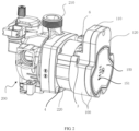
- FIG. 1 is a front view of a control box according to an embodiment of the present disclosure
- FIG. 2 is a schematic diagram of the control box installed on a pump according to an embodiment of the present disclosure
- a pump 200 is a machine that conveys fluid or pressurizes the fluid.
- the pump 200 includes a pump body 210 and a drive motor (not shown in the figure), and the drive motor (not shown in the figure) may be installed in a housing 220.
- the drive motor is provided with a control box 100 configured to control operation of the drive motor (not shown in the figure).
- the control box 100 may be integrally installed on the housing 220.
- control box 100 also needs to be provided with an outgoing line adapter interface configured to connect a signal line or a power line extracted from a client.
- the client is configured to transmit a control signal or supply power to the control box 100 to control operation of the drive motor (not shown in the figure).
- the control box 100 provided by this embodiment may be suitable for optimizing space occupancy of the control box 100.
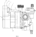
- FIG. 3 is a side view of the pump provided with the control box according to an embodiment of the present disclosure
- FIG. 4 is a schematic cross-sectional view of the pump provided with the control box according to an embodiment of the present disclosure.
- the control box 100 includes a box body 110 and a box cover 120.
- the box cover 120 is matched with the box body 110 and is covered on the box body 110.
- both the box body 110 and the box cover 120 include a first region 111 and a second part 112, wherein the first region 111 of the box body 110 is corresponding to the first region 111 of the box cover 120, and the second region 112 of the box body 110 is corresponding to the second region 112 of the box cover 120.
- the first region 111 and the second region 112 are in terms of relative location. Actually, the first region 111 and the second region 112 may be integrally molded.
- the first region 111 of the control box 100 is integrally arranged on an end part, axially away from the pump body 210, of the housing 220 of the pump 200, and the first region 111 is matched with the end part.
- the first region 111 of the box body 110 is detachably installed on the end part, such that the integral first region 111 of the control box 100 is detachably installed on the end part.
- the integral second region 112 of the control box 100 is formed in a way that the integral first region of the control box 100 extends outwards in a radial direction of the housing 220.
- an empty space is formed between the second region 112 of the control box 100 and the pump body 210, such that the control box 100 can make full use of space between the axial end part of the housing 220 and a periphery of the end part to reasonably utilize narrow space. In this way, adaptability of the control box 100 to a use environment with strict requirements for space is improved.
- the first region 111 of the box body 110 is connected to the axial end part of the housing 220 by a plurality of bolts 3. Further, an escape structure corresponding to the bolts 3 is respectively arranged on the box body 110 and the box cover 120 of the control box 100. Alternatively, the escape structure is an escape slot.
- a dimension of the end part of the housing 220 is a square surrounded by four R160, and the first region 111of the box body 110 may be arranged in the square to avoid a nut 4 for fixing the housing 220 and the pump body 210.
- the first region 111 of the box body 110 is connected to the housing 220 by a bolt 3, and the first region 111 of the box body 110 is also provided with an escape structure such as an escape slot to avoid the bolt 3.
- the second region 112 may extend outwards between adjacent escape structures (such as escape slots) in a radial direction of the housing 220.
- the second region 112 is formed by extending in the radial direction (similarly vertical to an axial line 5 as shown in FIG. 3 ) of the housing 220, a width of the second region 112 may be less than or equal to a distance between two adjacent bolts 3, and an extension length of the second part 112 jointly depends on a diameter D of the end part of the housing 220 and a width of an outgoing line adapter module 6.
- control box 100 may be installed on the housing 220 as an integral unit, such that the control box 100 and the pump 200 are installed separately as integral modules, and then are assembled together to facilitate scheduling of production.
- the technical solution of this embodiment solves the problems of space occupation and installation difficulty caused by narrow working environment of the pump 200 and larger size of an outgoing line adapter interface.
- the technical solution has following advantages.
- the outgoing line adapter module 6 is detachably installed on the housing 220.
- An aperture 130 may be arranged on a side, facing the pump body 210, of the second region 112 of the box body 110.
- the outgoing line adapter module 6 may be inserted into the aperture 130.
- the outgoing line adapter module 6 is configured to detachably install a wiring plug 7 in the axial direction of the housing 220, such that the wiring plug 7 is placed in the empty space 8.
- a receiving cavity is formed between the box cover 120 and the box body 110, and a control module 140 is arranged in the receiving cavity.
- An electrical contact point is provided on a side of the control module 140 facing the aperture 130, and the electrical contact point is arranged in correspondence with the aperture 130.
- the control module 140 may be a circuit board provided with the electrical contact point.
- the electrical contact point may be a conductive elastic piece arranged on the circuit board, and the wiring plug 7 may be pointconnected to the elastic piece through an adapter member (not shown in the figure) on the outgoing line adapter module 6.
- the adapter member (not shown in the figure) may be a power pin or a signal pin.
- an indicating member 151 (for example, an indicating lamp) is provided on a side of the control module 140 facing away from the aperture 130.
- the first region 111 of the box cover 120 is provided with a display panel 150, and the display panel 150 is provided with a transparent area and is configured to display the indicating member 151.
- the transparent area may be formed by providing a hole on the display panel 150 and then filling the hole with transparent zdPET or pasting the transparent zdPET on the hole.
- the zdPET is a milky white or light yellow and highly crystalline polymer with a smooth and shiny surface.
- the box body 110 is detachably connected to the box cover 120.
- the box body 110 is connected to the box cover 120 by a screw 9, and a waterproof member 10 (such as a rubber plug) is provided above the screw 9.
- the waterproof member 10 may play roles in embellishment, waterproofing and covering the screw 9.
Landscapes
- Engineering & Computer Science (AREA)
- Mechanical Engineering (AREA)
- General Engineering & Computer Science (AREA)
- Power Engineering (AREA)
- Microelectronics & Electronic Packaging (AREA)
- Computer Hardware Design (AREA)
- Structures Of Non-Positive Displacement Pumps (AREA)
- Details Of Reciprocating Pumps (AREA)
Description
- This application claims priority to
Chinese Patent Application No. 202010468057.X, titled "CONTROL BOX FOR PUMP" and filed on May 28, 2020 - The present disclosure relates to the field of pump technologies, and more particularly, to a control box for a pump.
- A pump is a machine that conveys fluid or pressurizes the fluid. Generally, a drive motor is provided in the pump. The drive motor is provided with a control box configured to control operation of the drive motor. Generally, the control box of the drive motor may be installed on a periphery of a radial side of the drive motor, or may be installed on an axial end part of the drive motor.
- Further, the control box also needs to be provided with an outgoing line adapter interface configured to connect a signal line or a power line. However, in general, a working environment of the pump is relatively narrow. In the above two installation modes, if the interface connects the signal line or the power line, too much space needs to be taken up, making the control box unable to adapt to places where installation environments are limited.
EP 1 204 194 A1 shows a pump driven by an electric motor whose speed can be regulated, with a motor housing accommodating a stator winding and with a pump housing forming an impeller chamber and adjoining the motor housing at the end face, wherein the components required for electronic regulation are accommodated in an electronics housing.
EP 3 034 879 A1
US 2016/079822A1 an electric fluid pump comprising a connection terminal wire segment of a winding wire which is positioned on a radial inner side of a guide groove of a crossover guide, and the guide groove of the crossover guide is shaped to extend circumferentially in such a direction that a radial distance is decreased gradually and thereby to set the takeout terminal wire segment of one phase on the radial inner side of crossover wire segments of the other phases.
US 2013/343935 A1 discloses a heat circulation pump, which includes a pump housing with a pump impeller arranged therein which is driven by an electric motor arranged in a motor housing which axially connects to the pump housing. The heat circulation pump also includes a terminal box which is axially connected to the motor housing in order to receive electric and/or electronic components of the engine control.
WO 2019/064767 A1 discloses a motor with a stator shell and a tubular housing. A terminal box consisting of several parts is mounted on the stator shell. - An objective of the present disclosure is to provide a control box for a pump to reasonably utilize space between an axial end part of a housing and a periphery of the end part, such that adaptability of the control box to narrow space is increased.
- To achieve the above objective, the present disclosure adopts technical solutions as set forth in claim 1. Further advantageous embodiments are set forth in the dependent claims.
- A control box for a pump includes:
a box body and a box cover, wherein the box cover is matched with the box body and is covered on the box body. - Both the box body and the box cover include a first region and a second region, wherein the first region of the box body is corresponding to the first region of the box cover, and the second region of the box body is corresponding to the second region of the box cover. The first regions are arranged on an end part, axially away from a pump body, of a housing of the pump, and the first regions are matched with the end part. The second regions are formed in a way that the second regions extend outwards in a radial direction of the housing, and an empty space is formed between the second regions and the pump body. The first region of the box body is detachably mounted on the end part.
- Further, the second region of the box body is provided with an aperture.
- Further, a receiving cavity is formed between the box cover and the box body, and a control module is arranged in the receiving cavity.
- An electrical contact point is provided on a side of the control module facing the aperture, and the electrical contact point is arranged in correspondence with the aperture.
- Further, an indicating member is provided on a side of the control module facing away from the aperture.
- The first region of the box cover is provided with a display panel.
- The display panel is provided with a transparent area and is configured to display the indicating member.
- Further, the first region of the box body is connected to the end part by a plurality of bolts.
- Further, an escape structure corresponding to the bolts is respectively arranged on the box body and the box cover of the control box.
- Further, the escape structure is an escape slot.
- Further, the second region extends outwards between adjacent escape structures in a radial direction of the housing, and a width of the second region is less than or equal to a distance between two adjacent bolts.
- Further, the box body is detachably connected to the box cover.
- Further, the box body is connected to the box cover by a screw, and a waterproof member is provided above the screw.
- Compared with the existing technologies, the box cover provided by the present disclosure has following advantages.
- 1. Space outside a profile of the axial end part of the housing is reasonably utilized, such that the control box is adapt to environments where installation space is limited, and thus environmental adaptability of the pump is improved.
- 2. Both assembly and disassembly of the control box are convenient, which will not cause unnecessary damage or destruction to components, and thus costs are reduced.
- 3. Modular design of the control box can improve efficiency of mass production of the control box.
-
-
FIG. 1 is a front view of a control box according to an embodiment of the present disclosure; -
FIG. 2 is a schematic diagram of the control box installed on a pump according to an embodiment of the present disclosure; -
FIG. 3 is a side view of the pump provided with the control box according to an embodiment of the present disclosure; and -
FIG. 4 is a schematic cross-sectional view of the pump provided with the control box according to an embodiment of the present disclosure. - In the drawings:
-
control box 100,box body 110,box cover 120,first region 111 of the box body,second region 112 of the box body,aperture 130,control module 140,display panel 150, indicatingmember 151; -
pump 200,pump body 210,housing 220;bolt 3,nut 4,axial line 5; - outgoing
line adapter module 6,wiring plug 7, empty space 8; andscrew 9, andwaterproof member 10. - The following embodiments are intended to describe the present disclosure but are not intended to limit the scope of the present disclosure, which is limited by the attached claims.
-
FIG. 1 is a front view of a control box according to an embodiment of the present disclosure; andFIG. 2 is a schematic diagram of the control box installed on a pump according to an embodiment of the present disclosure. Apump 200 is a machine that conveys fluid or pressurizes the fluid. As shown inFIG. 2 , generally, thepump 200 includes apump body 210 and a drive motor (not shown in the figure), and the drive motor (not shown in the figure) may be installed in ahousing 220. In addition, the drive motor is provided with acontrol box 100 configured to control operation of the drive motor (not shown in the figure). Further, thecontrol box 100 may be integrally installed on thehousing 220. Generally, thecontrol box 100 also needs to be provided with an outgoing line adapter interface configured to connect a signal line or a power line extracted from a client. The client is configured to transmit a control signal or supply power to thecontrol box 100 to control operation of the drive motor (not shown in the figure). Thecontrol box 100 provided by this embodiment may be suitable for optimizing space occupancy of thecontrol box 100. -
FIG. 3 is a side view of the pump provided with the control box according to an embodiment of the present disclosure; andFIG. 4 is a schematic cross-sectional view of the pump provided with the control box according to an embodiment of the present disclosure. - With reference to
FIG. 1 to FIG. 4 , thecontrol box 100 includes abox body 110 and abox cover 120. Thebox cover 120 is matched with thebox body 110 and is covered on thebox body 110. - With reference to
FIG. 1 , both thebox body 110 and thebox cover 120 include afirst region 111 and asecond part 112, wherein thefirst region 111 of thebox body 110 is corresponding to thefirst region 111 of thebox cover 120, and thesecond region 112 of thebox body 110 is corresponding to thesecond region 112 of thebox cover 120. - The
first region 111 and thesecond region 112 are in terms of relative location. Actually, thefirst region 111 and thesecond region 112 may be integrally molded. - Further, the
first region 111 of thecontrol box 100 is integrally arranged on an end part, axially away from thepump body 210, of thehousing 220 of thepump 200, and thefirst region 111 is matched with the end part. For example, thefirst region 111 of thebox body 110 is detachably installed on the end part, such that the integralfirst region 111 of thecontrol box 100 is detachably installed on the end part. - The integral
second region 112 of thecontrol box 100 is formed in a way that the integral first region of thecontrol box 100 extends outwards in a radial direction of thehousing 220. With reference toFIG. 4 , an empty space is formed between thesecond region 112 of thecontrol box 100 and thepump body 210, such that thecontrol box 100 can make full use of space between the axial end part of thehousing 220 and a periphery of the end part to reasonably utilize narrow space. In this way, adaptability of thecontrol box 100 to a use environment with strict requirements for space is improved. - In an embodiment, with reference to
FIG. 1 to FIG. 2 , thefirst region 111 of thebox body 110 is connected to the axial end part of thehousing 220 by a plurality ofbolts 3. Further, an escape structure corresponding to thebolts 3 is respectively arranged on thebox body 110 and thebox cover 120 of thecontrol box 100. Alternatively, the escape structure is an escape slot. - For example, in a specific embodiment, with reference to
FIG. 1 to FIG 3 , a dimension of the end part of thehousing 220 is a square surrounded by four R160, and the first region 111of thebox body 110 may be arranged in the square to avoid anut 4 for fixing thehousing 220 and thepump body 210. Further, thefirst region 111 of thebox body 110 is connected to thehousing 220 by abolt 3, and thefirst region 111 of thebox body 110 is also provided with an escape structure such as an escape slot to avoid thebolt 3. Thesecond region 112 may extend outwards between adjacent escape structures (such as escape slots) in a radial direction of thehousing 220. For example, thesecond region 112 is formed by extending in the radial direction (similarly vertical to anaxial line 5 as shown inFIG. 3 ) of thehousing 220, a width of thesecond region 112 may be less than or equal to a distance between twoadjacent bolts 3, and an extension length of thesecond part 112 jointly depends on a diameter D of the end part of thehousing 220 and a width of an outgoingline adapter module 6. - During use, the
control box 100 may be installed on thehousing 220 as an integral unit, such that thecontrol box 100 and thepump 200 are installed separately as integral modules, and then are assembled together to facilitate scheduling of production. - The technical solution of this embodiment solves the problems of space occupation and installation difficulty caused by narrow working environment of the
pump 200 and larger size of an outgoing line adapter interface. Thus the technical solution has following advantages. - 1. Space outside a profile of the axial end part of the housing is reasonably utilized, such that the control box is adapt to environments where installation space is limited, and thus environmental adaptability of the pump is improved.
- 2. Both assembly and disassembly of the control box are convenient, which will not cause unnecessary damage or destruction to components, and thus costs are reduced.
- 3. Modular design of the control box can improve efficiency of mass production of the control box.
- On the basis of the above technical solution, with reference to
FIG. 2 to FIG. 4 , the outgoingline adapter module 6 is detachably installed on thehousing 220. Anaperture 130 may be arranged on a side, facing thepump body 210, of thesecond region 112 of thebox body 110. When thefirst region 111 of thebox body 110 is installed on the end part, the outgoingline adapter module 6 may be inserted into theaperture 130. Further, the outgoingline adapter module 6 is configured to detachably install awiring plug 7 in the axial direction of thehousing 220, such that thewiring plug 7 is placed in the empty space 8. - Further, with reference to
FIG. 4 , a receiving cavity is formed between thebox cover 120 and thebox body 110, and acontrol module 140 is arranged in the receiving cavity. - An electrical contact point is provided on a side of the
control module 140 facing theaperture 130, and the electrical contact point is arranged in correspondence with theaperture 130. When the outgoingline adapter module 6 is inserted into theaperture 130 and thewiring plug 7 is inserted into the outgoingline adapter module 6, thewiring plug 7 is electrically connected to the electrical contact point. - The
control module 140 may be a circuit board provided with the electrical contact point. The electrical contact point may be a conductive elastic piece arranged on the circuit board, and thewiring plug 7 may be pointconnected to the elastic piece through an adapter member (not shown in the figure) on the outgoingline adapter module 6. The adapter member (not shown in the figure) may be a power pin or a signal pin. - Alternatively, with reference to
FIG. 1 to FIG. 3 , an indicating member 151 (for example, an indicating lamp) is provided on a side of thecontrol module 140 facing away from theaperture 130. Thefirst region 111 of thebox cover 120 is provided with adisplay panel 150, and thedisplay panel 150 is provided with a transparent area and is configured to display the indicatingmember 151. The transparent area may be formed by providing a hole on thedisplay panel 150 and then filling the hole with transparent zdPET or pasting the transparent zdPET on the hole. The zdPET is a milky white or light yellow and highly crystalline polymer with a smooth and shiny surface. - On the basis of the above technical solution, with reference to
FIG. 4 , thebox body 110 is detachably connected to thebox cover 120. Alternatively, thebox body 110 is connected to thebox cover 120 by ascrew 9, and a waterproof member 10 (such as a rubber plug) is provided above thescrew 9. Thewaterproof member 10 may play roles in embellishment, waterproofing and covering thescrew 9.
Claims (6)
- A control box (100) for a pump (200) comprising a pump body (210) and a housing (220) of the pump, which are arranged in the axial direction, the control box (100) comprising:a box body (110) and a box cover (120), the box cover (120) being matched with the box body (110) and being covered on the box body (110); andboth the box body (110) and the box cover (120) comprising a first region (111) and a second region (112), the first region (111) of the box body (110) being corresponding to the first region (111) of the box cover (120), and the second region (112) of the box body (110) being corresponding to the second region (112) of the box cover (120); the first regions (111) are configured to be arranged on an end part, axially away from the pump body (210), of the housing (220) of the pump, and the first regions (111) being matched with the end part; the second regions (112) being formed in a way that the second regions (112) extend outwards in a radial direction of the housing (220), and an empty space (8) being formed between the second regions (112) and the pump body (210) when the control box (100) is arranged on the pump (200); and the first region (111) of the box body (110) being configured to be detachably mounted on the end part of the housing (220), the control box being characterised in that an outgoing line adapter module (6) which is configured to detachably install a wiring plug (7) in an axial direction of the housing (220) is inserted into an aperture (130) arranged on a side of the second region (112) of the box body (110) configured to face the pump body (210) , such that the wiring plug (7) is placed in the empty space (8),wherein the first region (111) of the box body (110) is configured to be connected to the end part of the housing (220) by a plurality of bolts (3),wherein an escape structure corresponding to the bolts (3) is respectively arranged on the box body (110) and the box cover (120) of the control box (100),wherein the second region (112) extends outwards between adjacent escape structures in a radial direction of the housing (220), and a width of the second region (112) is less than or equal to a distance between two adjacent bolts (3).
- The control box (100) according to claim 1, wherein a receiving cavity is formed between the box cover (120) and the box body (110), and a control module (140) is arranged in the receiving cavity; and
an electrical contact point is provided on a side of the control module (140) facing the aperture (130), and the electrical contact point is arranged in correspondence with the aperture (130). - The control box (100) according to claim 2, wherein an indicating member (151) is provided on a side of the control module (130) facing away from the aperture (130);
the first region (111) of the box cover (120) is provided with a display panel (150); and the display panel (150) is provided with a transparent area and is configured to display the indicating member (151). - The control box (100) according to claim any of the preceding claims, wherein the escape structure is an escape slot.
- The control box (100) according to any of the preceding claims, wherein the box body (110) is detachably connected to the box cover (120).
- The control box (100) according to claim 5, wherein the box body (110) is connected to the box cover (120) by a screw (9), and a waterproof member (10) is provided above the screw(9).
Applications Claiming Priority (1)
| Application Number | Priority Date | Filing Date | Title |
|---|---|---|---|
| CN202010468057.XA CN111608896B (en) | 2020-05-28 | 2020-05-28 | Control box for pump |
Publications (3)
| Publication Number | Publication Date |
|---|---|
| EP3916233A1 EP3916233A1 (en) | 2021-12-01 |
| EP3916233B1 true EP3916233B1 (en) | 2024-12-11 |
| EP3916233C0 EP3916233C0 (en) | 2024-12-11 |
Family
ID=72198645
Family Applications (1)
| Application Number | Title | Priority Date | Filing Date |
|---|---|---|---|
| EP21175437.9A Active EP3916233B1 (en) | 2020-05-28 | 2021-05-21 | Control box for pump |
Country Status (2)
| Country | Link |
|---|---|
| EP (1) | EP3916233B1 (en) |
| CN (1) | CN111608896B (en) |
Families Citing this family (1)
| Publication number | Priority date | Publication date | Assignee | Title |
|---|---|---|---|---|
| CN116771664A (en) * | 2023-08-08 | 2023-09-19 | 浙江弘霸科技有限公司 | Booster pump |
Citations (2)
| Publication number | Priority date | Publication date | Assignee | Title |
|---|---|---|---|---|
| US20130343935A1 (en) * | 2011-03-12 | 2013-12-26 | Finn Mathiesen Høj | Heat circulation pump |
| WO2019064767A1 (en) * | 2017-09-28 | 2019-04-04 | 日本電産株式会社 | Motor, and electric power steering device |
Family Cites Families (12)
| Publication number | Priority date | Publication date | Assignee | Title |
|---|---|---|---|---|
| EP1204194A1 (en) * | 2000-11-03 | 2002-05-08 | WILO GmbH | Axially plugable electronic housing |
| GB0105641D0 (en) * | 2001-03-08 | 2001-04-25 | Lucas Industries Ltd | Improvements in electric motor driven hydraulic pumps |
| DE602004023556D1 (en) * | 2003-05-28 | 2009-11-26 | Aisin Seiki | Electrically driven pump |
| JP2016059208A (en) * | 2014-09-11 | 2016-04-21 | 日立オートモティブシステムズ株式会社 | Electric fluid pump |
| CN204327521U (en) * | 2014-12-18 | 2015-05-13 | 合肥新沪屏蔽泵有限公司 | Pump assembly |
| CN205779911U (en) * | 2016-05-27 | 2016-12-07 | 合肥新沪屏蔽泵有限公司 | A kind of lightweight pump assembly |
| US11070106B2 (en) * | 2017-07-31 | 2021-07-20 | Nidec Tosok Corporation | Electric oil pump |
| CN110513300A (en) * | 2019-08-19 | 2019-11-29 | 新界泵业(浙江)有限公司 | Shield circulating pump |
| CN111638659B (en) * | 2020-05-28 | 2024-11-26 | 合肥新沪屏蔽泵有限公司 | A control box |
| CN212391717U (en) * | 2020-05-28 | 2021-01-22 | 合肥新沪屏蔽泵有限公司 | Control box |
| CN111668674B (en) * | 2020-05-28 | 2025-03-28 | 合肥新沪屏蔽泵有限公司 | A pump outlet adapter module |
| CN212717116U (en) * | 2020-05-28 | 2021-03-16 | 合肥新沪屏蔽泵有限公司 | Control box for pump |
-
2020
- 2020-05-28 CN CN202010468057.XA patent/CN111608896B/en active Active
-
2021
- 2021-05-21 EP EP21175437.9A patent/EP3916233B1/en active Active
Patent Citations (2)
| Publication number | Priority date | Publication date | Assignee | Title |
|---|---|---|---|---|
| US20130343935A1 (en) * | 2011-03-12 | 2013-12-26 | Finn Mathiesen Høj | Heat circulation pump |
| WO2019064767A1 (en) * | 2017-09-28 | 2019-04-04 | 日本電産株式会社 | Motor, and electric power steering device |
Also Published As
| Publication number | Publication date |
|---|---|
| EP3916233C0 (en) | 2024-12-11 |
| CN111608896A (en) | 2020-09-01 |
| CN111608896B (en) | 2025-07-25 |
| EP3916233A1 (en) | 2021-12-01 |
Similar Documents
| Publication | Publication Date | Title |
|---|---|---|
| US8299662B2 (en) | Motor connecting box and converter motor | |
| CN107228074B (en) | Electronic water pump | |
| CN106089739B (en) | Hot water circulating pump | |
| KR102623212B1 (en) | Air compressor | |
| EP3916234B1 (en) | Outgoing line adapter module for pump | |
| CN209860673U (en) | Non-contact rotary conductive slip ring | |
| US20260104045A1 (en) | Electric pump | |
| EP3916233A1 (en) | Control box for pump | |
| CN212717116U (en) | Control box for pump | |
| CN210000169U (en) | Integrated control device and electric vehicle | |
| CN109510407B (en) | Integrated system of motor and controller | |
| CN216699748U (en) | Special frequency conversion integral type motor of fan | |
| CN211223593U (en) | Electric power steering controller | |
| CN217789439U (en) | Motor end cover, driving system and vehicle | |
| CN222321247U (en) | A waterproof integrated stepping motor | |
| CN220420947U (en) | Actuator assembly, actuator module and coating die head | |
| CN219718040U (en) | Stable flow regulating motor | |
| CN216851552U (en) | Integrated waterproof servo motor structure | |
| CN224138849U (en) | Industrial gantry cranes with concealed wiring | |
| CN223321856U (en) | Outlet wire structure for motor stator, motor stator, motor and vehicle | |
| CN221227321U (en) | Mining frequency conversion all-in-one | |
| CN223039832U (en) | Electronic oil pump | |
| CN218243206U (en) | Electric machine | |
| CN217590521U (en) | Permanent magnet synchronous motor integrated with variable frequency driver | |
| US12546321B2 (en) | Electric pump |
Legal Events
| Date | Code | Title | Description |
|---|---|---|---|
| PUAI | Public reference made under article 153(3) epc to a published international application that has entered the european phase |
Free format text: ORIGINAL CODE: 0009012 |
|
| STAA | Information on the status of an ep patent application or granted ep patent |
Free format text: STATUS: THE APPLICATION HAS BEEN PUBLISHED |
|
| AK | Designated contracting states |
Kind code of ref document: A1 Designated state(s): AL AT BE BG CH CY CZ DE DK EE ES FI FR GB GR HR HU IE IS IT LI LT LU LV MC MK MT NL NO PL PT RO RS SE SI SK SM TR |
|
| B565 | Issuance of search results under rule 164(2) epc |
Effective date: 20211019 |
|
| STAA | Information on the status of an ep patent application or granted ep patent |
Free format text: STATUS: REQUEST FOR EXAMINATION WAS MADE |
|
| 17P | Request for examination filed |
Effective date: 20220530 |
|
| RBV | Designated contracting states (corrected) |
Designated state(s): AL AT BE BG CH CY CZ DE DK EE ES FI FR GB GR HR HU IE IS IT LI LT LU LV MC MK MT NL NO PL PT RO RS SE SI SK SM TR |
|
| STAA | Information on the status of an ep patent application or granted ep patent |
Free format text: STATUS: EXAMINATION IS IN PROGRESS |
|
| 17Q | First examination report despatched |
Effective date: 20230718 |
|
| GRAP | Despatch of communication of intention to grant a patent |
Free format text: ORIGINAL CODE: EPIDOSNIGR1 |
|
| STAA | Information on the status of an ep patent application or granted ep patent |
Free format text: STATUS: GRANT OF PATENT IS INTENDED |
|
| INTG | Intention to grant announced |
Effective date: 20240705 |
|
| RIN1 | Information on inventor provided before grant (corrected) |
Inventor name: WANG, YUANG Inventor name: WANG, YONG Inventor name: WANG, JINCHAO Inventor name: LI, YOUYUAN Inventor name: ZHANG, LI Inventor name: HU, ZHI Inventor name: WANG, YUKUAN Inventor name: HU, QIYONG Inventor name: DING, JUNFENG Inventor name: WANG, GUOLIANG |
|
| GRAS | Grant fee paid |
Free format text: ORIGINAL CODE: EPIDOSNIGR3 |
|
| GRAA | (expected) grant |
Free format text: ORIGINAL CODE: 0009210 |
|
| STAA | Information on the status of an ep patent application or granted ep patent |
Free format text: STATUS: THE PATENT HAS BEEN GRANTED |
|
| AK | Designated contracting states |
Kind code of ref document: B1 Designated state(s): AL AT BE BG CH CY CZ DE DK EE ES FI FR GB GR HR HU IE IS IT LI LT LU LV MC MK MT NL NO PL PT RO RS SE SI SK SM TR |
|
| REG | Reference to a national code |
Ref country code: GB Ref legal event code: FG4D |
|
| REG | Reference to a national code |
Ref country code: CH Ref legal event code: EP |
|
| REG | Reference to a national code |
Ref country code: DE Ref legal event code: R096 Ref document number: 602021023126 Country of ref document: DE |
|
| REG | Reference to a national code |
Ref country code: IE Ref legal event code: FG4D |
|
| U01 | Request for unitary effect filed |
Effective date: 20241223 |
|
| U07 | Unitary effect registered |
Designated state(s): AT BE BG DE DK EE FI FR IT LT LU LV MT NL PT RO SE SI Effective date: 20250114 |
|
| PG25 | Lapsed in a contracting state [announced via postgrant information from national office to epo] |
Ref country code: HR Free format text: LAPSE BECAUSE OF FAILURE TO SUBMIT A TRANSLATION OF THE DESCRIPTION OR TO PAY THE FEE WITHIN THE PRESCRIBED TIME-LIMIT Effective date: 20241211 |
|
| PG25 | Lapsed in a contracting state [announced via postgrant information from national office to epo] |
Ref country code: ES Free format text: LAPSE BECAUSE OF FAILURE TO SUBMIT A TRANSLATION OF THE DESCRIPTION OR TO PAY THE FEE WITHIN THE PRESCRIBED TIME-LIMIT Effective date: 20241211 |
|
| PG25 | Lapsed in a contracting state [announced via postgrant information from national office to epo] |
Ref country code: NO Free format text: LAPSE BECAUSE OF FAILURE TO SUBMIT A TRANSLATION OF THE DESCRIPTION OR TO PAY THE FEE WITHIN THE PRESCRIBED TIME-LIMIT Effective date: 20250311 |
|
| PG25 | Lapsed in a contracting state [announced via postgrant information from national office to epo] |
Ref country code: GR Free format text: LAPSE BECAUSE OF FAILURE TO SUBMIT A TRANSLATION OF THE DESCRIPTION OR TO PAY THE FEE WITHIN THE PRESCRIBED TIME-LIMIT Effective date: 20250312 |
|
| PG25 | Lapsed in a contracting state [announced via postgrant information from national office to epo] |
Ref country code: RS Free format text: LAPSE BECAUSE OF FAILURE TO SUBMIT A TRANSLATION OF THE DESCRIPTION OR TO PAY THE FEE WITHIN THE PRESCRIBED TIME-LIMIT Effective date: 20250311 |
|
| U20 | Renewal fee for the european patent with unitary effect paid |
Year of fee payment: 5 Effective date: 20250528 |
|
| PG25 | Lapsed in a contracting state [announced via postgrant information from national office to epo] |
Ref country code: SM Free format text: LAPSE BECAUSE OF FAILURE TO SUBMIT A TRANSLATION OF THE DESCRIPTION OR TO PAY THE FEE WITHIN THE PRESCRIBED TIME-LIMIT Effective date: 20241211 |
|
| PG25 | Lapsed in a contracting state [announced via postgrant information from national office to epo] |
Ref country code: PL Free format text: LAPSE BECAUSE OF FAILURE TO SUBMIT A TRANSLATION OF THE DESCRIPTION OR TO PAY THE FEE WITHIN THE PRESCRIBED TIME-LIMIT Effective date: 20241211 |
|
| PG25 | Lapsed in a contracting state [announced via postgrant information from national office to epo] |
Ref country code: IS Free format text: LAPSE BECAUSE OF FAILURE TO SUBMIT A TRANSLATION OF THE DESCRIPTION OR TO PAY THE FEE WITHIN THE PRESCRIBED TIME-LIMIT Effective date: 20250411 |
|
| PG25 | Lapsed in a contracting state [announced via postgrant information from national office to epo] |
Ref country code: SK Free format text: LAPSE BECAUSE OF FAILURE TO SUBMIT A TRANSLATION OF THE DESCRIPTION OR TO PAY THE FEE WITHIN THE PRESCRIBED TIME-LIMIT Effective date: 20241211 |
|
| PG25 | Lapsed in a contracting state [announced via postgrant information from national office to epo] |
Ref country code: CZ Free format text: LAPSE BECAUSE OF FAILURE TO SUBMIT A TRANSLATION OF THE DESCRIPTION OR TO PAY THE FEE WITHIN THE PRESCRIBED TIME-LIMIT Effective date: 20241211 |
|
| PLBE | No opposition filed within time limit |
Free format text: ORIGINAL CODE: 0009261 |
|
| STAA | Information on the status of an ep patent application or granted ep patent |
Free format text: STATUS: NO OPPOSITION FILED WITHIN TIME LIMIT |
|
| REG | Reference to a national code |
Ref country code: CH Ref legal event code: L10 Free format text: ST27 STATUS EVENT CODE: U-0-0-L10-L00 (AS PROVIDED BY THE NATIONAL OFFICE) Effective date: 20251022 |
|
| 26N | No opposition filed |
Effective date: 20250912 |
|
| REG | Reference to a national code |
Ref country code: CH Ref legal event code: H13 Free format text: ST27 STATUS EVENT CODE: U-0-0-H10-H13 (AS PROVIDED BY THE NATIONAL OFFICE) Effective date: 20251223 |
|
| PG25 | Lapsed in a contracting state [announced via postgrant information from national office to epo] |
Ref country code: CH Free format text: LAPSE BECAUSE OF NON-PAYMENT OF DUE FEES Effective date: 20250531 |
|
| GBPC | Gb: european patent ceased through non-payment of renewal fee |
Effective date: 20250521 |
|
| PG25 | Lapsed in a contracting state [announced via postgrant information from national office to epo] |
Ref country code: MC Free format text: LAPSE BECAUSE OF FAILURE TO SUBMIT A TRANSLATION OF THE DESCRIPTION OR TO PAY THE FEE WITHIN THE PRESCRIBED TIME-LIMIT Effective date: 20241211 |
|
| PG25 | Lapsed in a contracting state [announced via postgrant information from national office to epo] |
Ref country code: GB Free format text: LAPSE BECAUSE OF NON-PAYMENT OF DUE FEES Effective date: 20250521 |
|
| PG25 | Lapsed in a contracting state [announced via postgrant information from national office to epo] |
Ref country code: IE Free format text: LAPSE BECAUSE OF NON-PAYMENT OF DUE FEES Effective date: 20250521 |