EP3916227A1 - Pump system with tube guides - Google Patents
Pump system with tube guides Download PDFInfo
- Publication number
- EP3916227A1 EP3916227A1 EP21176081.4A EP21176081A EP3916227A1 EP 3916227 A1 EP3916227 A1 EP 3916227A1 EP 21176081 A EP21176081 A EP 21176081A EP 3916227 A1 EP3916227 A1 EP 3916227A1
- Authority
- EP
- European Patent Office
- Prior art keywords
- tube
- tubing
- passage
- tube guide
- collar
- Prior art date
- Legal status (The legal status is an assumption and is not a legal conclusion. Google has not performed a legal analysis and makes no representation as to the accuracy of the status listed.)
- Granted
Links
Images

Classifications
-
- F—MECHANICAL ENGINEERING; LIGHTING; HEATING; WEAPONS; BLASTING
- F04—POSITIVE - DISPLACEMENT MACHINES FOR LIQUIDS; PUMPS FOR LIQUIDS OR ELASTIC FLUIDS
- F04B—POSITIVE-DISPLACEMENT MACHINES FOR LIQUIDS; PUMPS
- F04B43/00—Machines, pumps, or pumping installations having flexible working members
- F04B43/12—Machines, pumps, or pumping installations having flexible working members having peristaltic action
- F04B43/1253—Machines, pumps, or pumping installations having flexible working members having peristaltic action by using two or more rollers as squeezing elements, the rollers moving on an arc of a circle during squeezing
-
- F—MECHANICAL ENGINEERING; LIGHTING; HEATING; WEAPONS; BLASTING
- F04—POSITIVE - DISPLACEMENT MACHINES FOR LIQUIDS; PUMPS FOR LIQUIDS OR ELASTIC FLUIDS
- F04B—POSITIVE-DISPLACEMENT MACHINES FOR LIQUIDS; PUMPS
- F04B43/00—Machines, pumps, or pumping installations having flexible working members
- F04B43/12—Machines, pumps, or pumping installations having flexible working members having peristaltic action
-
- F—MECHANICAL ENGINEERING; LIGHTING; HEATING; WEAPONS; BLASTING
- F04—POSITIVE - DISPLACEMENT MACHINES FOR LIQUIDS; PUMPS FOR LIQUIDS OR ELASTIC FLUIDS
- F04B—POSITIVE-DISPLACEMENT MACHINES FOR LIQUIDS; PUMPS
- F04B43/00—Machines, pumps, or pumping installations having flexible working members
- F04B43/0009—Special features
- F04B43/0081—Special features systems, control, safety measures
-
- F—MECHANICAL ENGINEERING; LIGHTING; HEATING; WEAPONS; BLASTING
- F04—POSITIVE - DISPLACEMENT MACHINES FOR LIQUIDS; PUMPS FOR LIQUIDS OR ELASTIC FLUIDS
- F04B—POSITIVE-DISPLACEMENT MACHINES FOR LIQUIDS; PUMPS
- F04B43/00—Machines, pumps, or pumping installations having flexible working members
- F04B43/12—Machines, pumps, or pumping installations having flexible working members having peristaltic action
- F04B43/1253—Machines, pumps, or pumping installations having flexible working members having peristaltic action by using two or more rollers as squeezing elements, the rollers moving on an arc of a circle during squeezing
- F04B43/1261—Machines, pumps, or pumping installations having flexible working members having peristaltic action by using two or more rollers as squeezing elements, the rollers moving on an arc of a circle during squeezing the rollers being placed at the outside of the tubular flexible member
Definitions
- the present disclosure is generally directed to a peristaltic pump system. More particularly, the present disclosure is directed to a peristaltic pump system having improved tube guides and tubing.
- pump rollers act against a section of tubing disposed through the pump to move fluid through the tubing.
- the tubing must be fixed at least at the inlet of the pump, because otherwise the rotary motion of the pump rollers would feed the tubing through the pump.
- the tubing must be fixed at both ends of the pump, because either end may function as the inlet.
- the tubing is fixed relative to the pump using a tube guide that compresses or squeezes the tubing.
- a tube guide or holder may have a circular opening with an inner diameter smaller than the outer diameter of the tubing.
- the tube guide must compress the tube sufficiently to keep the tubing fixed in the tube guide, while limiting blockage of the fluid flow through the tubing caused by compression of the tubing. Consequently, the inner diameter of the tube guide is usually only slightly smaller than the outer diameter of the tubing.
- the tubing is disposed through the pump by the user, and then is fixed in place at the ends by disposing the tubing in the tube guides. Because the tubing that is disposed through the pump and fixed in the tube guides is merely a section of a longer length of tubing, the specific amount of tubing fixed between the tube guides can and will vary. The user's judgement may result in the section of tubing disposed between the guides to be stretched (or "tight"), causing the inner diameter of the tubing to narrow and impacting flow rate. Alternatively, the user may fix a section of tubing between the guides that can move relative to the tube guides (or "loose"), leading to kinking and twisting of the tubing as the tube rollers of the pump act on the tubing in the pump.
- Kinking can occur within the pumping area, or at a junction just prior to the tube guide on the outlet end of the pump. Kinking is to be particularly avoided because in addition to altering the flow rates, it may also lead to tubing failures and leaking. Kinks in the tubing can also lead to high shear rates in the fluid being pumped, and this can in turn lead to damage in the fluid (e.g., damage to the cells in the fluid). For example, when pumping blood, kinks in the tubing can lead to hemolysis.
- a peristaltic pump system in an aspect, includes a length of tubing having first and second ends.
- the tubing has an outer diameter, a first tube collar fixedly attached to the tubing at a first position between the first and second ends and extending outwardly of the outer diameter, and a second tube collar fixedly attached to the tubing at a second position spaced from the first position between the first and second ends and extending outwardly of the outer diameter.
- the system also includes a rotary peristaltic pump with an arcuate tube channel having a first end and a second end, the length of tubing disposed in the arcuate tube channel, and a rotor configured to contact the length of tubing disposed in the arcuate tube channel to move fluid through the length of tubing.
- the system further includes a first tube guide disposed at the first end of the tube channel and a second tube guide disposed at the second end of the tube channel.
- the first and second tube guides each include a passage therethrough with an inner diameter that is larger than the outer diameter of the tubing, and an opening in communication with the passage through which the length of tubing is disposed into the passage.
- the first tube guide has an unrestricted shoulder configured to abut the first tube collar with the length of tubing in the arcuate tube channel in an installation state
- the second tube guide has an unrestricted shoulder configured to abut the second tube collar with the length of tubing in the arcuate tube channel in the installation state.
- the passage of the first tube guide is disposed between the unrestricted shoulder of the first tube guide and the first end of the arcuate tube channel, and the passage of the second tube guide is disposed between the unrestricted shoulder of the second tube guide and the second end of the arcuate tube channel.
- Figs. 1-3 illustrate an embodiment of a peristaltic pump system 100.
- the system 100 includes a length of tubing 102, a rotary peristaltic pump 104, and first and second tube guides 106, 108.
- the length of tubing 102 has first and second ends 110, 112.
- the tubing 102 also has an outer diameter, with a first tube collar 120 and a second tube collar 122 fixedly attached to the tubing 102.
- the collars 120, 122 may be attached to the tubing 102 using cyclohexanone solvent bonding.
- the first tube collar 120 is attached at a first position 124 between the first and second ends 110, 112.
- the second tube collar 122 is attached to the tubing at a second position 126 spaced from the first position 124 between the first and second ends 110, 112. Both the first and second tube collars 120, 122 extend outwardly of the outer diameter of the tubing 102.
- the rotary peristaltic pump 104 has an arcuate tube channel 130 with a first end 132 and a second end 134.
- the length of tubing 102 is disposed in the arcuate tube channel 130, and a rotor of the pump 104 contacts the length of tubing 102 disposed in the arcuate tube channel 130 to move fluid through the length of tubing 102.
- the first tube guide 106 is disposed at the first end 132 of the tube channel 130, and the second tube guide 108 is disposed at the second end 134 of the tube channel 130.
- the first and second tube guides 106, 108 each include a passage 150, 250 therethrough with an inner diameter (d i ) that is larger than the outer diameter (d o ) of the tubing 102 (compare Fig. 1 with Figs. 7 and 10 ), and an opening 152, 252 in communication with the passage 150, 250 through which the length of tubing 102 is disposed into the passage 150, 250 (see Figs. 5, 6 and 8, 9 ).
- the first tube guide 106 has an unrestricted shoulder or surface 154 configured to abut the first tube collar 120 with the length of tubing 102 in the arcuate tube channel 130 in an installation state (see Fig. 3 ).
- the second tube guide 108 has an unrestricted shoulder or surface 254 configured to abut the second tube collar 122 with the length of tubing 102 in the arcuate tube channel 130 in the installation state.
- the unrestricted shoulder 154, 254 is a structure that abuts the tube collar 120, 122 to limit axial motion toward the pump 104, but does not limit or prevent motion of the tube collar 122, 124 axially away from the shoulder 154, 254 (and thus away from the pump 104) or rotationally relative to the shoulder 154, 254.
- the shoulder 154, 254 does not prevent the tubing 102 attached to the collar 120, 122 from moving axially away from the shoulder 154, 254 such that it is no longer abutting the shoulder 154, 254. See, e.g., Fig. 4 .
- the shoulder 154, 254 does not prevent the tubing 102 from rotating about its own axis.
- the passage 150 of the first tube guide 106 is disposed between the unrestricted shoulder 154 of the first tube guide 106 and the first end 132 of the arcuate tube channel 130 (compare Fig. 7 and Fig. 3 ). Further, the passage 250 of the second tube guide 108 is disposed between the unrestricted shoulder 254 of the second tube guide 108 and the second end 134 of the arcuate tube channel 130 (compare Fig. 10 and Fig. 3 ).
- the section of the tubing 102 between the first and second collars 120, 122 is disposed into the arcuate tube channel 130.
- the ends 110, 112 of the tubing 102 may be pulled slightly so that the tubing 102 may be inserted into the tube guides 106, 108, with the collars 120, 122 disposed axially outwardly from the shoulders 154, 254.
- the tension applied to the end or ends 110, 112 may be released, at which point the collars 120, 122 may move axially in the direction of the shoulders 154, 254. See Fig. 3 .
- the section of tubing 102 between the first and second collars 120, 122 may be slightly in tension even after the tubing is permitted to relax.
- the tubing 102 may rotate relative to the guides 106, 108 to prevent or relieve any twist from developing in the tubing 102. Furthermore, if the tubing 102 experiences stretching in a portion of the tubing 102, the collar 120, 122 may move axially away from the shoulder 154, 254 to limit or prevent kinking in the tubing 102.
- Fig. 4 illustrates a state where the collar 120 has moved axially away from the shoulder 154 to limit or prevent kinking at the end 110 of the tubing as a consequence of the operation of the pump 104 on the tubing 102, with a gap formed between the collar 120 and the shoulder 154.
- the pump 104 is a rotary peristaltic pump, such as may be included as part of an AURORA® or AURORA Xi® automated cell processing system, both of which are available from Fresenius Kabi USA, Lake Zurich, Illinois. More particularly, peristaltic pump 104 may be a bidirectional peristaltic pump.
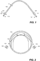
- Fig. 1 illustrates an embodiment of the length of tubing 102 with first and second tube collars 120, 122.
- the first tube collar 120 and the second tube collar 122 each comprise an annular collar disposed about the tubing 102.
- the first and second annular collars 120, 122 each have an outer diameter (D o ) that is larger than the outer diameter (d o ) of the tubing 102.
- the annular collars 120, 122 are continuous and regular about a periphery of an outer surface of the tubing 102. That is, the collar 120, 122 extends entirely about the circumference of the tubing 102, and the shape of the collar 120, 122 is uniform or identical about the circumference.
- both the first and second tube collars 120, 122 are cylindrical.
- the collar 120, 122 could not be discontinuous or irregular according to other embodiments.
- one or both of the collars 120, 122 could have an outer edge of varying distance from the center of the collar, like a gear with many "teeth” or only a few "teeth”.
- one of both of the collars 120, 122 could have a C-shape, and thus be discontinuous about the circumference of the tubing 102.
- the collar 120, 122 should not be shaped such that a portion of the collar may incidentally interact with, for example, the opening 152, 252 to the passage 150, 250 to prevent the collar from rotating freely relative to the shoulder 154, 254. Consequently, it is particularly advantageous for the collar to be continuous and uniform, such as in the form of a cylinder in the illustrated embodiment.
- the unrestricted shoulder 154, 254 of the first tube guide 106 and the second tube guide 108 may be discontinuous, e.g., where the opening 152, 252 is in communication with the passage 150, 250. Still, the unrestricted shoulder 154 of the first tube guide 106 may be continuous except where the opening 152 is in communication with the passage 150 of the first tube guide 106, and the unrestricted shoulder 254 of the second tube guide 108 may be continuous except where the opening 252 is in communication with the passage 250 of the second tube guide 108.
- the unrestricted shoulder 154 of the first tube guide 106 may be disposed about at least 80% of a periphery of the passage 150 of the first tube guide 106
- the unrestricted shoulder 254 of the second tube guide 108 may be disposed about at least 80% of a periphery of the passage 150 of the second tube guide 108, for example.
- one of the first tube collar 120 and the unrestricted shoulder 154 of the first tube guide 106 should be continuous and the other of the first tube collar 120 and the unrestricted shoulder 154 of the first tube guide 106 may be discontinuous.
- one of the second tube collar 122 and the unrestricted shoulder 254 of the second tube guide 108 should be continuous and the other of the second tube collar 122 and the unrestricted shoulder 254 of the second tube guide 108 may be discontinuous.
- a gate may be used in conjunction with the shoulder 154, 254, which gate is moved into place over the opening 152, 252 when the tubing 102 is in position.
- the first and second tube collars 120, 122 may be identical in structure. According to other embodiments, the tube collars 120, 122 may have a different shape, for example one may be longer in an axial direction along the tubing than the other collar. The relationship between the passages 150, 250, shoulders 154, 254 and tube collars 120, 122 as recited above will remain the same even in such an embodiment.
- the distance between the tube collars 120, 122 is selected such that when the collars 120, 122 are installed, the length of tubing 102 between the tube collars 120, 122 is placed in a state of tension.
- a distance between the unrestricted shoulder 154 of the first tube guide 106 and the unrestricted shoulder 254 of the second tube guide 108 along a path through the arcuate tube channel 130 is greater than a distance between the first tube collar 120 and the second tube collar 122 in a relaxed state.
- the degree of tension is selected such that the tubing 102 resists kinking without interfering substantially with the flow therethrough.
- the distance between the tube collars may be selected such that the tubing 102 is not in tension.
- the passage 150 of the first tube guide 106 has a first end 156 and a second end 158, and the shoulder 154 of the first tube guide 106 is disposed at the first end 156 of the passage 150 of the first tube guide 106.
- the passage 250 of the second tube guide 108 has a first end 256 and a second end 258, and the shoulder 254 of the second tube guide 108 is disposed at the first end 256 of the passage 250 of the second tube guide 108.
- a distance between the second ends 158, 258 of the passages 150, 250 of the first and second tube guides 106, 108 is smaller than a distance between the first ends 156, 256 of the passages 150, 250 of the first and second tube guides 106, 108 (compare Fig. 3 with Figs. 7 and 10 ).
- the first tube guide 106 may include a second passage 160 with an inner diameter (D i ) that is larger than the inner diameter (d i ) of the passage 150, the second passage 160 having a first end 162 and a second end 164, the first end 162 of the second passage 160 connected to the second end 158 of the passage 150 and the second end 164 of the second passage 160 defining an unrestricted axial opening 166.
- the second tube guide 108 also may include a second passage 260 with an inner diameter that is larger than the inner diameter of the passage 250, the second passage 260 having a first end 262 and a second end 264, the first end 262 of the second passage 260 connected to the second end 258 of the passage 250 and the second end 264 of the second passage 260 defining an unrestricted axial opening 266.
- the interfaces between the passages 150, 250 and the second passages 160, 260 are lead-in or funnel features that ensure that, even if the tube guide 106, 108 is slightly rotated, the tubing 102 will be able to slide through the tube guide 106, 108 without pinching.
- the system 100 provides certain advantages relative to conventional pump systems using conventional tube guides or holders. Because the tube guides or holders are loose on the tubing (i.e., the inner diameter of the passage is greater than the outer diameter of the tubing), the tubing can be stretched such that the tube collar is well past the tube holder during loading. When the user releases the tubing after loading, the tubing will contract until the tube collars abut the tube guides. This may prevent flow rate inaccuracies caused by operator over-stretching of the tubing during loading when disposing tubing in a standard tubing guide.
- any increased tube length caused by insufficient tubing line tension at loading (e.g., tubing collars too far apart) or stretching of the tubing during operation will not be trapped between the guide and the pump, causing kinking. Instead, the tube is free to move relative to the guide, creating a gap between the tube collar and the tube guide, limiting or eliminating the risk of kinking. In particular, see Fig. 4 . Additionally, because the tubing is free to rotate, the tube damage because of twisting or coiling can be limited or prevented.
- the pump system of any of the previous embodiments is provided, wherein a distance between the unrestricted shoulder of the first tube guide and the unrestricted shoulder of the second tube guide along a path through the arcuate tube channel is greater than a distance between the first tube collar and the second tube collar in a relaxed state.
- the pump system of any of the previous embodiments wherein the unrestricted shoulder of the first tube guide is continuous except where the opening is in communication with the passage of the first tube guide, and the unrestricted shoulder of the second tube guide is continuous except where the opening is in communication with the passage of the second tube guide.
- the pump system of any of the previous embodiments wherein the unrestricted shoulder of the first tube guide is disposed about at least 80% of a periphery of the passage of the first tube guide, and unrestricted shoulder of the second tube guide is disposed about at least 80% of a periphery of the passage of the second tube guide.
- the pump system of any of the previous embodiments wherein the first tube collar and the second tube collar each comprise an annular collar disposed about the tubing, the annular collar having an outer diameter that is larger than the outer diameter of the tubing.
- the pump system of any of the previous embodiments, in particular of the embodiment of [0048] is provided, wherein the annular collar is continuous and regular about a periphery of an outer surface of the tubing.
- the pump system of any of the previous embodiments, in particular of the embodiment of [0049] is provided, wherein the annular collar is a cylindrical collar.
- the pump system of any of the previous embodiments in particular of any of the embodiments of [0043]-[0045], is provided, wherein one of the first tube collar and the unrestricted shoulder of the first tube guide is continuous and the other of the first tube collar and the unrestricted shoulder of the first tube guide is discontinuous, and one of the second tube collar and the unrestricted shoulder of the second tube guide is continuous and the other of the second tube collar and the unrestricted shoulder of the second tube guide is discontinuous.
- the pump system of any of the previous embodiments wherein the first tube guide is identical to the second tube guide, and the first tube collar is identical to the second tube collar.
- the pump system of any of the previous embodiments is provided , wherein the peristaltic pump is a bidirectional peristaltic pump.
Landscapes
- Engineering & Computer Science (AREA)
- Mechanical Engineering (AREA)
- General Engineering & Computer Science (AREA)
- Reciprocating Pumps (AREA)
Abstract
Description
- The present disclosure is generally directed to a peristaltic pump system. More particularly, the present disclosure is directed to a peristaltic pump system having improved tube guides and tubing.
- In a conventional rotary peristaltic pump, pump rollers act against a section of tubing disposed through the pump to move fluid through the tubing. The tubing must be fixed at least at the inlet of the pump, because otherwise the rotary motion of the pump rollers would feed the tubing through the pump. Where the pump is a bi-directional pump, the tubing must be fixed at both ends of the pump, because either end may function as the inlet.
- Conventionally, the tubing is fixed relative to the pump using a tube guide that compresses or squeezes the tubing. For example, a tube guide or holder may have a circular opening with an inner diameter smaller than the outer diameter of the tubing.
- Care must be taken in the design of the tube guide. The tube guide must compress the tube sufficiently to keep the tubing fixed in the tube guide, while limiting blockage of the fluid flow through the tubing caused by compression of the tubing. Consequently, the inner diameter of the tube guide is usually only slightly smaller than the outer diameter of the tubing.
- Typically, the tubing is disposed through the pump by the user, and then is fixed in place at the ends by disposing the tubing in the tube guides. Because the tubing that is disposed through the pump and fixed in the tube guides is merely a section of a longer length of tubing, the specific amount of tubing fixed between the tube guides can and will vary. The user's judgement may result in the section of tubing disposed between the guides to be stretched (or "tight"), causing the inner diameter of the tubing to narrow and impacting flow rate. Alternatively, the user may fix a section of tubing between the guides that can move relative to the tube guides (or "loose"), leading to kinking and twisting of the tubing as the tube rollers of the pump act on the tubing in the pump.
- Kinking can occur within the pumping area, or at a junction just prior to the tube guide on the outlet end of the pump. Kinking is to be particularly avoided because in addition to altering the flow rates, it may also lead to tubing failures and leaking. Kinks in the tubing can also lead to high shear rates in the fluid being pumped, and this can in turn lead to damage in the fluid (e.g., damage to the cells in the fluid). For example, when pumping blood, kinks in the tubing can lead to hemolysis.
- In addition, when the section of tubing is loaded into the pump, the user must orient the tubing properly. Differences in tubing orientation can lead to twist in the tubing that can lead to differences in flow rate, like the stretching or kinking that can occur because of improper length of the section of tubing between the tube guides.
- It would be desirable to provide a pump system that overcame, at least in part, the disadvantages of conventional rotary peristaltic pump systems.
- In an aspect, a peristaltic pump system includes a length of tubing having first and second ends. The tubing has an outer diameter, a first tube collar fixedly attached to the tubing at a first position between the first and second ends and extending outwardly of the outer diameter, and a second tube collar fixedly attached to the tubing at a second position spaced from the first position between the first and second ends and extending outwardly of the outer diameter. The system also includes a rotary peristaltic pump with an arcuate tube channel having a first end and a second end, the length of tubing disposed in the arcuate tube channel, and a rotor configured to contact the length of tubing disposed in the arcuate tube channel to move fluid through the length of tubing. The system further includes a first tube guide disposed at the first end of the tube channel and a second tube guide disposed at the second end of the tube channel. The first and second tube guides each include a passage therethrough with an inner diameter that is larger than the outer diameter of the tubing, and an opening in communication with the passage through which the length of tubing is disposed into the passage. The first tube guide has an unrestricted shoulder configured to abut the first tube collar with the length of tubing in the arcuate tube channel in an installation state, and the second tube guide has an unrestricted shoulder configured to abut the second tube collar with the length of tubing in the arcuate tube channel in the installation state. The passage of the first tube guide is disposed between the unrestricted shoulder of the first tube guide and the first end of the arcuate tube channel, and the passage of the second tube guide is disposed between the unrestricted shoulder of the second tube guide and the second end of the arcuate tube channel.
-
-
Fig. 1 is a side view of an embodiment of a length of tubing having first and second tube collars fixedly attached thereto. -
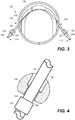
Fig. 2 is a side view of an embodiment of a rotary peristaltic pump with first and second tube guides disposed at either end of the pump before the length of tubing ofFig. 1 is disposed in the pump and tube guides. -
Fig. 3 is a side view of the rotary peristaltic pump and tube guides ofFig. 2 after the length of tubing ofFig. 1 is disposed through the pump and tube guides. -
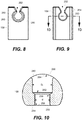
Fig. 4 is an enlarged, partially cross-sectional view of the tubing and first tube collar ofFig. 1 and the associated first tube guide ofFig. 2 , with the stretching of the tubing caused by the operation of the pump causing displacement of the tube collar relative to the respective tube guide. -
Fig. 5 is a side view of an embodiment of the first tube guide or holder. -
Fig. 6 is an opposite side view of the tube guide ofFig. 5 . -
Fig. 7 is a cross-sectional view of the tube guide ofFig. 5 taken along line 7-7 inFig. 6 . -
Fig. 8 is a side view of an embodiment of the second tube guide or holder. -
Fig. 9 is an opposite side view of the tube guide ofFig. 8 . -
Fig. 10 is a cross-sectional view of the tube guide ofFig. 8 taken along line 10-10 inFig. 9 . - A more detailed description of the systems and methods in accordance with the present disclosure is set forth below. It should be understood that the description below of specific devices and methods is intended to be exemplary, and not exhaustive of all possible variations or applications. Thus, the scope of the disclosure is not intended to be limiting, and should be understood to encompass variations or embodiments that would occur to persons of ordinary skill.
-
Figs. 1-3 illustrate an embodiment of aperistaltic pump system 100. Thesystem 100 includes a length oftubing 102, a rotaryperistaltic pump 104, and first andsecond tube guides - As seen in
Figs. 1 and3 , the length oftubing 102 has first andsecond ends tubing 102 also has an outer diameter, with afirst tube collar 120 and asecond tube collar 122 fixedly attached to thetubing 102. For example, thecollars tubing 102 using cyclohexanone solvent bonding. Thefirst tube collar 120 is attached at afirst position 124 between the first andsecond ends second tube collar 122 is attached to the tubing at asecond position 126 spaced from thefirst position 124 between the first andsecond ends second tube collars tubing 102. - As seen in
Figs. 2 and3 , the rotaryperistaltic pump 104 has anarcuate tube channel 130 with afirst end 132 and asecond end 134. The length oftubing 102 is disposed in thearcuate tube channel 130, and a rotor of thepump 104 contacts the length oftubing 102 disposed in thearcuate tube channel 130 to move fluid through the length oftubing 102. Thefirst tube guide 106 is disposed at thefirst end 132 of thetube channel 130, and thesecond tube guide 108 is disposed at thesecond end 134 of thetube channel 130. - As best seen in
Figs. 5-7 and8-10 , the first andsecond tube guides passage Fig. 1 withFigs. 7 and10 ), and anopening passage tubing 102 is disposed into thepassage 150, 250 (seeFigs. 5, 6 and8, 9 ). Thefirst tube guide 106 has an unrestricted shoulder orsurface 154 configured to abut thefirst tube collar 120 with the length oftubing 102 in thearcuate tube channel 130 in an installation state (seeFig. 3 ). Similarly, thesecond tube guide 108 has an unrestricted shoulder orsurface 254 configured to abut thesecond tube collar 122 with the length oftubing 102 in thearcuate tube channel 130 in the installation state. - The
unrestricted shoulder tube collar pump 104, but does not limit or prevent motion of thetube collar shoulder 154, 254 (and thus away from the pump 104) or rotationally relative to theshoulder shoulder tubing 102 attached to thecollar shoulder shoulder Fig. 4 . Further, theshoulder tubing 102 from rotating about its own axis. - The
passage 150 of thefirst tube guide 106 is disposed between theunrestricted shoulder 154 of thefirst tube guide 106 and thefirst end 132 of the arcuate tube channel 130 (compareFig. 7 andFig. 3 ). Further, thepassage 250 of thesecond tube guide 108 is disposed between theunrestricted shoulder 254 of thesecond tube guide 108 and thesecond end 134 of the arcuate tube channel 130 (compareFig. 10 andFig. 3 ). - During installation of the
tubing 102, the section of thetubing 102 between the first andsecond collars arcuate tube channel 130. The ends 110, 112 of thetubing 102 may be pulled slightly so that thetubing 102 may be inserted into the tube guides 106, 108, with thecollars shoulders collars shoulders Fig. 3 . Because of the comparative distances between thecollars guides shoulders tubing 102 between the first andsecond collars - During operation of the
pump 104, thetubing 102 may rotate relative to theguides tubing 102. Furthermore, if thetubing 102 experiences stretching in a portion of thetubing 102, thecollar shoulder tubing 102. For example,Fig. 4 illustrates a state where thecollar 120 has moved axially away from theshoulder 154 to limit or prevent kinking at theend 110 of the tubing as a consequence of the operation of thepump 104 on thetubing 102, with a gap formed between thecollar 120 and theshoulder 154. - Having thus explained the structure, installation and operation of the system in general terms, the details of the structure of the
system 100 are now discussed with reference first toFigs. 1-3 . - As mentioned above, the
pump 104 is a rotary peristaltic pump, such as may be included as part of an AURORA® or AURORA Xi® automated cell processing system, both of which are available from Fresenius Kabi USA, Lake Zurich, Illinois. More particularly,peristaltic pump 104 may be a bidirectional peristaltic pump. -
Fig. 1 illustrates an embodiment of the length oftubing 102 with first andsecond tube collars first tube collar 120 and thesecond tube collar 122 each comprise an annular collar disposed about thetubing 102. The first and secondannular collars tubing 102. - According to this embodiment, the
annular collars tubing 102. That is, thecollar tubing 102, and the shape of thecollar second tube collars - This should not be taken as suggesting that the
collar collars collars tubing 102. - However, because the intent is for the
collar shoulder opening passage shoulder - As a consequence of the use of a continuous and
regular tube collar unrestricted shoulder first tube guide 106 and thesecond tube guide 108 may be discontinuous, e.g., where theopening passage unrestricted shoulder 154 of thefirst tube guide 106 may be continuous except where theopening 152 is in communication with thepassage 150 of thefirst tube guide 106, and theunrestricted shoulder 254 of thesecond tube guide 108 may be continuous except where theopening 252 is in communication with thepassage 250 of thesecond tube guide 108. More particularly, theunrestricted shoulder 154 of thefirst tube guide 106 may be disposed about at least 80% of a periphery of thepassage 150 of thefirst tube guide 106, and theunrestricted shoulder 254 of thesecond tube guide 108 may be disposed about at least 80% of a periphery of thepassage 150 of thesecond tube guide 108, for example. - As general proposition, one of the
first tube collar 120 and theunrestricted shoulder 154 of thefirst tube guide 106 should be continuous and the other of thefirst tube collar 120 and theunrestricted shoulder 154 of thefirst tube guide 106 may be discontinuous. In a similar fashion, one of thesecond tube collar 122 and theunrestricted shoulder 254 of thesecond tube guide 108 should be continuous and the other of thesecond tube collar 122 and theunrestricted shoulder 254 of thesecond tube guide 108 may be discontinuous. To permit theshoulder tubing 102 to be introduced into thetube guide shoulder opening tubing 102 is in position. - According to embodiments such as the one illustrated in the Figures, the first and
second tube collars tube collars passages tube collars - According to the illustrated embodiment, the distance between the
tube collars collars tubing 102 between thetube collars unrestricted shoulder 154 of thefirst tube guide 106 and theunrestricted shoulder 254 of thesecond tube guide 108 along a path through thearcuate tube channel 130 is greater than a distance between thefirst tube collar 120 and thesecond tube collar 122 in a relaxed state. For the reasons provided above, the degree of tension is selected such that thetubing 102 resists kinking without interfering substantially with the flow therethrough. According to an alternative embodiment, the distance between the tube collars may be selected such that thetubing 102 is not in tension. - Additionally, according to the illustrated embodiments, the
passage 150 of thefirst tube guide 106 has afirst end 156 and asecond end 158, and theshoulder 154 of thefirst tube guide 106 is disposed at thefirst end 156 of thepassage 150 of thefirst tube guide 106. Similarly, thepassage 250 of thesecond tube guide 108 has afirst end 256 and asecond end 258, and theshoulder 254 of thesecond tube guide 108 is disposed at thefirst end 256 of thepassage 250 of thesecond tube guide 108. Finally, a distance between the second ends 158, 258 of thepassages passages Fig. 3 withFigs. 7 and10 ). - As to the embodiments of the tube guides as illustrated in
Figs. 5-10 , thefirst tube guide 106 may include asecond passage 160 with an inner diameter (Di) that is larger than the inner diameter (di) of thepassage 150, thesecond passage 160 having afirst end 162 and asecond end 164, thefirst end 162 of thesecond passage 160 connected to thesecond end 158 of thepassage 150 and thesecond end 164 of thesecond passage 160 defining an unrestrictedaxial opening 166. According to this embodiment, thesecond tube guide 108 also may include asecond passage 260 with an inner diameter that is larger than the inner diameter of thepassage 250, thesecond passage 260 having afirst end 262 and asecond end 264, thefirst end 262 of thesecond passage 260 connected to thesecond end 258 of thepassage 250 and thesecond end 264 of thesecond passage 260 defining an unrestrictedaxial opening 266. The interfaces between thepassages second passages tube guide tubing 102 will be able to slide through thetube guide - The
system 100 according to the disclosed embodiments provides certain advantages relative to conventional pump systems using conventional tube guides or holders. Because the tube guides or holders are loose on the tubing (i.e., the inner diameter of the passage is greater than the outer diameter of the tubing), the tubing can be stretched such that the tube collar is well past the tube holder during loading. When the user releases the tubing after loading, the tubing will contract until the tube collars abut the tube guides. This may prevent flow rate inaccuracies caused by operator over-stretching of the tubing during loading when disposing tubing in a standard tubing guide. Further, any increased tube length caused by insufficient tubing line tension at loading (e.g., tubing collars too far apart) or stretching of the tubing during operation will not be trapped between the guide and the pump, causing kinking. Instead, the tube is free to move relative to the guide, creating a gap between the tube collar and the tube guide, limiting or eliminating the risk of kinking. In particular, seeFig. 4 . Additionally, because the tubing is free to rotate, the tube damage because of twisting or coiling can be limited or prevented. - Thus, an improved pump system has been disclosed, in conjunction with an improved tubing set or kit and improved tube guides or holders. The description provided above, and the other aspects provided below, are intended for illustrative purposes, and are not intended to limit the scope of the disclosure to any particular method, system, apparatus or device described herein.
- In one embodiment a peristaltic pump system is provided comprising:
- a length of tubing having first and second ends,
- the tubing having an outer diameter, a first tube collar fixedly attached to the tubing at a first position between the first and second ends and extending outwardly of the outer diameter, and a second tube collar fixedly attached to the tubing at a second position spaced from the first position between the first and second ends and extending outwardly of the outer diameter;
- a rotary peristaltic pump with an arcuate tube channel having a first end and a second end, the length of tubing disposed in the arcuate tube channel, and a rotor configured to contact the length of tubing disposed in the arcuate tube channel to move fluid through the length of tubing; and
- a first tube guide disposed at the first end of the tube channel and a second tube guide disposed at the second end of the tube channel,
- the first and second tube guides each comprising a passage therethrough with an inner diameter that is larger than the outer diameter of the tubing, and an opening in communication with the passage through which the length of tubing is disposed into the passage,
- the first tube guide having an unrestricted shoulder configured to abut the first tube collar with the length of tubing in the arcuate tube channel in an installation state, and the second tube guide having an unrestricted shoulder configured to abut the second tube collar with the length of tubing in the arcuate tube channel in the installation state, and
- the passage of the first tube guide disposed between the unrestricted shoulder of the first tube guide and the first end of the arcuate tube channel, and the passage of the second tube guide disposed between the unrestricted shoulder of the second tube guide and the second end of the arcuate tube channel.
- In a further embodiments said pump system comprises further:
- the first tube guide comprises another passage with an inner diameter that is larger than the inner diameter of the passage, the another passage having a first end connected to the passage and a second end, and
- the second tube guide comprises another passage with an inner diameter that is larger than the inner diameter of the passage, the another passage having a first end connected to the passage and a second end.
- In yet a further embodiment the pump system of any of the previous embodiments is provided, wherein a distance between the unrestricted shoulder of the first tube guide and the unrestricted shoulder of the second tube guide along a path through the arcuate tube channel is greater than a distance between the first tube collar and the second tube collar in a relaxed state.
- In still a further embodiment the pump system of any of the previous embodiments is provided, wherein the unrestricted shoulder of the first tube guide is continuous except where the opening is in communication with the passage of the first tube guide, and the unrestricted shoulder of the second tube guide is continuous except where the opening is in communication with the passage of the second tube guide.
- In yet a further embodiment the pump system of any of the previous embodiments is provided, wherein the unrestricted shoulder of the first tube guide is disposed about at least 80% of a periphery of the passage of the first tube guide, and unrestricted shoulder of the second tube guide is disposed about at least 80% of a periphery of the passage of the second tube guide.
- In still a further embodiment the pump system of any of the previous embodiments is provided, wherein the first tube collar and the second tube collar each comprise an annular collar disposed about the tubing, the annular collar having an outer diameter that is larger than the outer diameter of the tubing.
- In a further embodiment the pump system of any of the previous embodiments, in particular of the embodiment of [0048] is provided, wherein the annular collar is continuous and regular about a periphery of an outer surface of the tubing.
- In a further embodiment the pump system of any of the previous embodiments, in particular of the embodiment of [0049] is provided, wherein the annular collar is a cylindrical collar.
- In yet a further embodiment the pump system of any of the previous embodiments, in particular of any of the embodiments of [0043]-[0045], is provided, wherein one of the first tube collar and the unrestricted shoulder of the first tube guide is continuous and the other of the first tube collar and the unrestricted shoulder of the first tube guide is discontinuous, and one of the second tube collar and the unrestricted shoulder of the second tube guide is continuous and the other of the second tube collar and the unrestricted shoulder of the second tube guide is discontinuous.
- In a further embodiment the pump system of any of the previous embodiments is provided, wherein:
- the passage of the first tube guide has a first end and a second end, and the unrestricted shoulder of the first tube guide is disposed at the first end of the passage of the first tube guide,
- the passage of the second tube guide has a first end and a second end, and the unrestricted shoulder of the second tube guide is disposed at the first end of the passage of the second tube guide, and
- a distance between the second ends of the passages of the first and second tube guides being smaller than a distance between the first ends of the passages of the first and second tube guides.
- In still another embodiment the pump system of any of the previous embodiments is provided, wherein the first tube guide is identical to the second tube guide, and the first tube collar is identical to the second tube collar.
- In a further embodiment the pump system of any of the previous embodiments is provided , wherein the peristaltic pump is a bidirectional peristaltic pump.
Claims (12)
- A peristaltic pump system comprising:a length of tubing having first and second ends,the tubing having an outer diameter, a first tube collar fixedly attached to the tubing at a first position between the first and second ends and extending outwardly of the outer diameter, and a second tube collar fixedly attached to the tubing at a second position spaced from the first position between the first andsecond ends and extending outwardly of the outer diameter;a rotary peristaltic pump with an arcuate tube channel having a first end and a second end, the length of tubing disposed in the arcuate tube channel, and a rotor configured to contact the length of tubing disposed in the arcuate tube channel to move fluid through the length of tubing; anda first tube guide disposed at the first end of the tube channel and a second tube guide disposed at the second end of the tube channel,the first and second tube guides each comprising a passage therethrough with an inner diameter that is larger than the outer diameter of the tubing, and an opening in communication with the passage through which the length of tubing is disposed into the passage,the first tube guide having an unrestricted shoulder configured to abut the first tube collar with the length of tubing in the arcuate tube channel in an installation state, and the second tube guide having an unrestricted shoulder configured to abut the second tube collar with the length of tubing in the arcuate tube channel in the installation state, andthe passage of the first tube guide disposed between the unrestricted shoulder of the first tube guide and the first end of the arcuate tube channel, and the passage of the second tube guide disposed between the unrestricted shoulder of the second tube guide and the second end of the arcuate tube channel.
- The pump system according to claim 1, wherein:the first tube guide comprises another passage with an inner diameter that is larger than the inner diameter of the passage, the another passage having a first end connected to the passage and a second end, andthe second tube guide comprises another passage with an inner diameter that is larger than the inner diameter of the passage, the another passage having a first end connected to the passage and a second end.
- The pump system according to claim 1 or 2 wherein a distance between the unrestricted shoulder of the first tube guide and the unrestricted shoulder of the second tube guide along a path through the arcuate tube channel is greater than a distance between the first tube collar and the second tube collar in a relaxed state.
- The pump system according to any one of claims 1 to 3, wherein the unrestricted shoulder of the first tube guide is continuous except where the opening is in communication with the passage of the first tube guide, and the unrestricted shoulder of the second tube guide is continuous except where the opening is in communication with the passage of the second tube guide.
- The pump system according to claim 4, wherein the unrestricted shoulder of the first tube guide is disposed about at least 80% of a periphery of the passage of the first tube guide, and unrestricted shoulder of the second tube guide is disposed about at least 80% of a periphery of the passage of the second tube guide.
- The pump system according to any one of claims 1 to 5, wherein the first tube collar and the second tube collar each comprise an annular collar disposed about the tubing, the annular collar having an outer diameter that is larger than the outer diameter of the tubing.
- The pump system according to claim 6, wherein the annular collar is continuous and regular about a periphery of an outer surface of the tubing.
- The pump system according to claim 7, wherein the annular collar is a cylindrical collar.
- The pump system according to any one of claims 1 to 3, wherein one of the first tube collar and the unrestricted shoulder of the first tube guide is continuous and the other of the first tube collar and the unrestricted shoulder of the first tube guide is discontinuous, and one of the second tube collar and the unrestricted shoulder of the second tube guide is continuous and the other of the second tube collar and the unrestricted shoulder of the second tube guide is discontinuous.
- The pump system according to any one of claims 1 to 9, wherein:the passage of the first tube guide has a first end and a second end, and the unrestricted shoulder of the first tube guide is disposed at the first end of the passage of the first tube guide,the passage of the second tube guide has a first end and a second end, and the unrestricted shoulder of the second tube guide is disposed at the first end of the passage of the second tube guide, anda distance between the second ends of the passages of the first and second tube guides being smaller than a distance between the first ends of the passages of the first and second tube guides.
- The pump system according to any one of claims 1 to 10, wherein the first tube guide is identical to the second tube guide, and the first tube collar is identical to the second tube collar.
- The pump system according to any one of claims 1 to 11, wherein the rotary peristaltic pump is a bidirectional peristaltic pump.
Applications Claiming Priority (1)
| Application Number | Priority Date | Filing Date | Title |
|---|---|---|---|
| US202063031091P | 2020-05-28 | 2020-05-28 |
Publications (3)
| Publication Number | Publication Date |
|---|---|
| EP3916227A1 true EP3916227A1 (en) | 2021-12-01 |
| EP3916227C0 EP3916227C0 (en) | 2025-05-07 |
| EP3916227B1 EP3916227B1 (en) | 2025-05-07 |
Family
ID=76159251
Family Applications (1)
| Application Number | Title | Priority Date | Filing Date |
|---|---|---|---|
| EP21176081.4A Active EP3916227B1 (en) | 2020-05-28 | 2021-05-26 | Pump system with tube guides |
Country Status (3)
| Country | Link |
|---|---|
| US (1) | US12152578B2 (en) |
| EP (1) | EP3916227B1 (en) |
| PL (1) | PL3916227T3 (en) |
Citations (6)
| Publication number | Priority date | Publication date | Assignee | Title |
|---|---|---|---|---|
| US4184815A (en) * | 1977-03-14 | 1980-01-22 | Extracorporeal Medical Specialties, Inc. | Roller pump rotor with integral spring arms |
| EP0825345A2 (en) * | 1996-07-25 | 1998-02-25 | Kaneka Corporation | Tube type roller pump |
| EP1048848A1 (en) * | 1999-04-29 | 2000-11-02 | Watson-Marlow Limited | peristaltic pumps |
| US20060083644A1 (en) * | 2004-10-12 | 2006-04-20 | Zumbrum Michael A | Dynamically tensioned peristaltic tubing pump |
| EP2397695A1 (en) * | 2009-02-16 | 2011-12-21 | Nipro Corporation | Tube pump |
| US20130315763A1 (en) * | 2012-05-24 | 2013-11-28 | Cook Medical Technologies Llc | Peristaltic pump tubing securing system |
Family Cites Families (9)
| Publication number | Priority date | Publication date | Assignee | Title |
|---|---|---|---|---|
| US3502034A (en) * | 1968-08-20 | 1970-03-24 | Extracorporeal Med Spec | Roller pump heads |
| FR2533316A1 (en) * | 1982-09-22 | 1984-03-23 | Inst Francais Du Petrole | QUICK-RESPONSE METHOD AND DEVICE FOR DETECTING POOR COMBUSTION |
| US5213483A (en) * | 1991-06-19 | 1993-05-25 | Strato Medical Corporation | Peristaltic infusion pump with removable cassette and mechanically keyed tube set |
| US5326236A (en) * | 1993-09-24 | 1994-07-05 | Abbott Laboratories | Compliant rotor for an improved cartridge for drug infusion pump |
| EP0672830B1 (en) * | 1994-02-16 | 1998-05-06 | Stöckert Instrumente GmbH | Tube fixation device for roller pumps |
| US6041709A (en) * | 1998-11-12 | 2000-03-28 | Usadvantage, Inc. | Peristaltic pump for pumping ink or cleaning fluids in a printing machine |
| GB0416006D0 (en) | 2004-07-16 | 2004-08-18 | Alaris Medical U K Ltd | Infusion apparatus |
| CA2621593A1 (en) | 2005-09-23 | 2007-04-05 | Medtronic, Inc. | Tubing holding device for roller pumps |
| US8272857B2 (en) * | 2008-02-22 | 2012-09-25 | Medtronic Xomed, Inc. | Method and system for loading of tubing into a pumping device |
-
2021
- 2021-04-30 US US17/245,282 patent/US12152578B2/en active Active
- 2021-05-26 PL PL21176081.4T patent/PL3916227T3/en unknown
- 2021-05-26 EP EP21176081.4A patent/EP3916227B1/en active Active
Patent Citations (6)
| Publication number | Priority date | Publication date | Assignee | Title |
|---|---|---|---|---|
| US4184815A (en) * | 1977-03-14 | 1980-01-22 | Extracorporeal Medical Specialties, Inc. | Roller pump rotor with integral spring arms |
| EP0825345A2 (en) * | 1996-07-25 | 1998-02-25 | Kaneka Corporation | Tube type roller pump |
| EP1048848A1 (en) * | 1999-04-29 | 2000-11-02 | Watson-Marlow Limited | peristaltic pumps |
| US20060083644A1 (en) * | 2004-10-12 | 2006-04-20 | Zumbrum Michael A | Dynamically tensioned peristaltic tubing pump |
| EP2397695A1 (en) * | 2009-02-16 | 2011-12-21 | Nipro Corporation | Tube pump |
| US20130315763A1 (en) * | 2012-05-24 | 2013-11-28 | Cook Medical Technologies Llc | Peristaltic pump tubing securing system |
Also Published As
| Publication number | Publication date |
|---|---|
| EP3916227C0 (en) | 2025-05-07 |
| US20210372391A1 (en) | 2021-12-02 |
| EP3916227B1 (en) | 2025-05-07 |
| US12152578B2 (en) | 2024-11-26 |
| PL3916227T3 (en) | 2025-10-06 |
Similar Documents
| Publication | Publication Date | Title |
|---|---|---|
| US12529368B2 (en) | Peristaltic pump with offset rollers having different sized diameters | |
| US7520871B2 (en) | System and method for tension-activated fluid control | |
| CN113374675B (en) | Peristaltic pump | |
| RU2676585C2 (en) | Hose pump | |
| DE3326784C2 (en) | Peristaltic roller pump | |
| JP2003525085A (en) | Tube dependent free flow prevention valve | |
| EP0346784A1 (en) | Peristaltic pump adapted to operate simultaneously on two lines | |
| EP0438452A1 (en) | Valve means for enteral therapy administration set | |
| RU2766790C2 (en) | Holder for the curved section of a tube | |
| CN107206226A (en) | Pump line maintaining body | |
| WO2007133061A1 (en) | Intravenous drip set controller with flusher | |
| US5263831A (en) | Peristaltic pump | |
| EP3916227B1 (en) | Pump system with tube guides | |
| JP2004501686A (en) | Valve device operated by cracking pressure | |
| AU713503B2 (en) | Tension responsive pinch valve | |
| US11629790B2 (en) | Pinch clamp device | |
| WO2017102621A1 (en) | Valve arrangement for enteral feeding sets having multiple fluid sources | |
| US10322247B1 (en) | Intravenous therapy tubing connection system | |
| CN107715202A (en) | Peristaltic pump with rotary play | |
| CN111770764A (en) | Puncture suction device | |
| CN110327509A (en) | It is a kind of to prevent gravity flow valve based on transfusion system | |
| CN213759930U (en) | Infusion apparatus with adjustable length | |
| WO1989005406A1 (en) | Stretched tube pump | |
| JP6327837B2 (en) | Tube connector and liquid circuit | |
| EP3552636A1 (en) | Access cannula with blocking device |
Legal Events
| Date | Code | Title | Description |
|---|---|---|---|
| PUAI | Public reference made under article 153(3) epc to a published international application that has entered the european phase |
Free format text: ORIGINAL CODE: 0009012 |
|
| STAA | Information on the status of an ep patent application or granted ep patent |
Free format text: STATUS: THE APPLICATION HAS BEEN PUBLISHED |
|
| AK | Designated contracting states |
Kind code of ref document: A1 Designated state(s): AL AT BE BG CH CY CZ DE DK EE ES FI FR GB GR HR HU IE IS IT LI LT LU LV MC MK MT NL NO PL PT RO RS SE SI SK SM TR |
|
| B565 | Issuance of search results under rule 164(2) epc |
Effective date: 20211001 |
|
| STAA | Information on the status of an ep patent application or granted ep patent |
Free format text: STATUS: REQUEST FOR EXAMINATION WAS MADE |
|
| 17P | Request for examination filed |
Effective date: 20220601 |
|
| RBV | Designated contracting states (corrected) |
Designated state(s): AL AT BE BG CH CY CZ DE DK EE ES FI FR GB GR HR HU IE IS IT LI LT LU LV MC MK MT NL NO PL PT RO RS SE SI SK SM TR |
|
| STAA | Information on the status of an ep patent application or granted ep patent |
Free format text: STATUS: EXAMINATION IS IN PROGRESS |
|
| 17Q | First examination report despatched |
Effective date: 20230324 |
|
| GRAP | Despatch of communication of intention to grant a patent |
Free format text: ORIGINAL CODE: EPIDOSNIGR1 |
|
| STAA | Information on the status of an ep patent application or granted ep patent |
Free format text: STATUS: GRANT OF PATENT IS INTENDED |
|
| INTG | Intention to grant announced |
Effective date: 20241129 |
|
| GRAS | Grant fee paid |
Free format text: ORIGINAL CODE: EPIDOSNIGR3 |
|
| GRAA | (expected) grant |
Free format text: ORIGINAL CODE: 0009210 |
|
| STAA | Information on the status of an ep patent application or granted ep patent |
Free format text: STATUS: THE PATENT HAS BEEN GRANTED |
|
| AK | Designated contracting states |
Kind code of ref document: B1 Designated state(s): AL AT BE BG CH CY CZ DE DK EE ES FI FR GB GR HR HU IE IS IT LI LT LU LV MC MK MT NL NO PL PT RO RS SE SI SK SM TR |
|
| REG | Reference to a national code |
Ref country code: GB Ref legal event code: FG4D |
|
| REG | Reference to a national code |
Ref country code: CH Ref legal event code: EP |
|
| REG | Reference to a national code |
Ref country code: DE Ref legal event code: R096 Ref document number: 602021030276 Country of ref document: DE |
|
| REG | Reference to a national code |
Ref country code: IE Ref legal event code: FG4D |
|
| U01 | Request for unitary effect filed |
Effective date: 20250522 |
|
| U07 | Unitary effect registered |
Designated state(s): AT BE BG DE DK EE FI FR IT LT LU LV MT NL PT RO SE SI Effective date: 20250530 |
|
| U20 | Renewal fee for the european patent with unitary effect paid |
Year of fee payment: 5 Effective date: 20250527 |
|
| PG25 | Lapsed in a contracting state [announced via postgrant information from national office to epo] |
Ref country code: ES Free format text: LAPSE BECAUSE OF FAILURE TO SUBMIT A TRANSLATION OF THE DESCRIPTION OR TO PAY THE FEE WITHIN THE PRESCRIBED TIME-LIMIT Effective date: 20250507 |
|
| PG25 | Lapsed in a contracting state [announced via postgrant information from national office to epo] |
Ref country code: NO Free format text: LAPSE BECAUSE OF FAILURE TO SUBMIT A TRANSLATION OF THE DESCRIPTION OR TO PAY THE FEE WITHIN THE PRESCRIBED TIME-LIMIT Effective date: 20250807 Ref country code: GR Free format text: LAPSE BECAUSE OF FAILURE TO SUBMIT A TRANSLATION OF THE DESCRIPTION OR TO PAY THE FEE WITHIN THE PRESCRIBED TIME-LIMIT Effective date: 20250808 |
|
| PG25 | Lapsed in a contracting state [announced via postgrant information from national office to epo] |
Ref country code: HR Free format text: LAPSE BECAUSE OF FAILURE TO SUBMIT A TRANSLATION OF THE DESCRIPTION OR TO PAY THE FEE WITHIN THE PRESCRIBED TIME-LIMIT Effective date: 20250507 |
|
| PG25 | Lapsed in a contracting state [announced via postgrant information from national office to epo] |
Ref country code: RS Free format text: LAPSE BECAUSE OF FAILURE TO SUBMIT A TRANSLATION OF THE DESCRIPTION OR TO PAY THE FEE WITHIN THE PRESCRIBED TIME-LIMIT Effective date: 20250807 |
|
| PG25 | Lapsed in a contracting state [announced via postgrant information from national office to epo] |
Ref country code: IS Free format text: LAPSE BECAUSE OF FAILURE TO SUBMIT A TRANSLATION OF THE DESCRIPTION OR TO PAY THE FEE WITHIN THE PRESCRIBED TIME-LIMIT Effective date: 20250907 |
|
| REG | Reference to a national code |
Ref country code: CH Ref legal event code: H13 Free format text: ST27 STATUS EVENT CODE: U-0-0-H10-H13 (AS PROVIDED BY THE NATIONAL OFFICE) Effective date: 20251223 |
|
| PG25 | Lapsed in a contracting state [announced via postgrant information from national office to epo] |
Ref country code: SM Free format text: LAPSE BECAUSE OF FAILURE TO SUBMIT A TRANSLATION OF THE DESCRIPTION OR TO PAY THE FEE WITHIN THE PRESCRIBED TIME-LIMIT Effective date: 20250507 |
|
| PG25 | Lapsed in a contracting state [announced via postgrant information from national office to epo] |
Ref country code: CH Free format text: LAPSE BECAUSE OF NON-PAYMENT OF DUE FEES Effective date: 20250531 |
|
| PG25 | Lapsed in a contracting state [announced via postgrant information from national office to epo] |
Ref country code: CZ Free format text: LAPSE BECAUSE OF FAILURE TO SUBMIT A TRANSLATION OF THE DESCRIPTION OR TO PAY THE FEE WITHIN THE PRESCRIBED TIME-LIMIT Effective date: 20250507 |
|
| PG25 | Lapsed in a contracting state [announced via postgrant information from national office to epo] |
Ref country code: SK Free format text: LAPSE BECAUSE OF FAILURE TO SUBMIT A TRANSLATION OF THE DESCRIPTION OR TO PAY THE FEE WITHIN THE PRESCRIBED TIME-LIMIT Effective date: 20250507 |
|
| PG25 | Lapsed in a contracting state [announced via postgrant information from national office to epo] |
Ref country code: MC Free format text: LAPSE BECAUSE OF FAILURE TO SUBMIT A TRANSLATION OF THE DESCRIPTION OR TO PAY THE FEE WITHIN THE PRESCRIBED TIME-LIMIT Effective date: 20250507 |
|
| PLBE | No opposition filed within time limit |
Free format text: ORIGINAL CODE: 0009261 |
|
| STAA | Information on the status of an ep patent application or granted ep patent |
Free format text: STATUS: NO OPPOSITION FILED WITHIN TIME LIMIT |
|
| REG | Reference to a national code |
Ref country code: CH Ref legal event code: L10 Free format text: ST27 STATUS EVENT CODE: U-0-0-L10-L00 (AS PROVIDED BY THE NATIONAL OFFICE) Effective date: 20260318 |
|
| PG25 | Lapsed in a contracting state [announced via postgrant information from national office to epo] |
Ref country code: IE Free format text: LAPSE BECAUSE OF NON-PAYMENT OF DUE FEES Effective date: 20250526 |
|
| 26N | No opposition filed |
Effective date: 20260210 |
|
| U20 | Renewal fee for the european patent with unitary effect paid |
Year of fee payment: 6 Effective date: 20260527 |
|
| PGFP | Annual fee paid to national office [announced via postgrant information from national office to epo] |
Ref country code: GB Payment date: 20260527 Year of fee payment: 6 Ref country code: PL Payment date: 20260514 Year of fee payment: 6 |
|
| PG25 | Lapsed in a contracting state [announced via postgrant information from national office to epo] |
Ref country code: CY Free format text: LAPSE BECAUSE OF FAILURE TO SUBMIT A TRANSLATION OF THE DESCRIPTION OR TO PAY THE FEE WITHIN THE PRESCRIBED TIME-LIMIT Effective date: 20250507 |