EP3916202A1 - Variable guide vanes assembly - Google Patents
Variable guide vanes assembly Download PDFInfo
- Publication number
- EP3916202A1 EP3916202A1 EP21176746.2A EP21176746A EP3916202A1 EP 3916202 A1 EP3916202 A1 EP 3916202A1 EP 21176746 A EP21176746 A EP 21176746A EP 3916202 A1 EP3916202 A1 EP 3916202A1
- Authority
- EP
- European Patent Office
- Prior art keywords
- unison
- vgvs
- gas turbine
- assembly
- turbine engine
- Prior art date
- Legal status (The legal status is an assumption and is not a legal conclusion. Google has not performed a legal analysis and makes no representation as to the accuracy of the status listed.)
- Granted
Links
Images

Classifications
-
- F—MECHANICAL ENGINEERING; LIGHTING; HEATING; WEAPONS; BLASTING
- F04—POSITIVE - DISPLACEMENT MACHINES FOR LIQUIDS; PUMPS FOR LIQUIDS OR ELASTIC FLUIDS
- F04D—NON-POSITIVE-DISPLACEMENT PUMPS
- F04D29/00—Details, component parts, or accessories
- F04D29/40—Casings; Connections of working fluid
- F04D29/52—Casings; Connections of working fluid for axial pumps
- F04D29/54—Fluid-guiding means, e.g. diffusers
- F04D29/56—Fluid-guiding means, e.g. diffusers adjustable
- F04D29/563—Fluid-guiding means, e.g. diffusers adjustable specially adapted for elastic fluid pumps
-
- F—MECHANICAL ENGINEERING; LIGHTING; HEATING; WEAPONS; BLASTING
- F01—MACHINES OR ENGINES IN GENERAL; ENGINE PLANTS IN GENERAL; STEAM ENGINES
- F01D—NON-POSITIVE DISPLACEMENT MACHINES OR ENGINES, e.g. STEAM TURBINES
- F01D17/00—Regulating or controlling by varying flow
- F01D17/10—Final actuators
- F01D17/12—Final actuators arranged in stator parts
- F01D17/14—Final actuators arranged in stator parts varying effective cross-sectional area of nozzles or guide conduits
- F01D17/16—Final actuators arranged in stator parts varying effective cross-sectional area of nozzles or guide conduits by means of nozzle vanes
- F01D17/162—Final actuators arranged in stator parts varying effective cross-sectional area of nozzles or guide conduits by means of nozzle vanes for axial flow, i.e. the vanes turning around axes which are essentially perpendicular to the rotor centre line
-
- F—MECHANICAL ENGINEERING; LIGHTING; HEATING; WEAPONS; BLASTING
- F01—MACHINES OR ENGINES IN GENERAL; ENGINE PLANTS IN GENERAL; STEAM ENGINES
- F01D—NON-POSITIVE DISPLACEMENT MACHINES OR ENGINES, e.g. STEAM TURBINES
- F01D17/00—Regulating or controlling by varying flow
- F01D17/20—Devices dealing with sensing elements or final actuators or transmitting means between them, e.g. power-assisted
- F01D17/22—Devices dealing with sensing elements or final actuators or transmitting means between them, e.g. power-assisted the operation or power assistance being predominantly non-mechanical
- F01D17/26—Devices dealing with sensing elements or final actuators or transmitting means between them, e.g. power-assisted the operation or power assistance being predominantly non-mechanical fluid, e.g. hydraulic
-
- F—MECHANICAL ENGINEERING; LIGHTING; HEATING; WEAPONS; BLASTING
- F01—MACHINES OR ENGINES IN GENERAL; ENGINE PLANTS IN GENERAL; STEAM ENGINES
- F01D—NON-POSITIVE DISPLACEMENT MACHINES OR ENGINES, e.g. STEAM TURBINES
- F01D25/00—Component parts, details, or accessories, not provided for in, or of interest apart from, other groups
- F01D25/24—Casings; Casing parts, e.g. diaphragms, casing fastenings
-
- F—MECHANICAL ENGINEERING; LIGHTING; HEATING; WEAPONS; BLASTING
- F04—POSITIVE - DISPLACEMENT MACHINES FOR LIQUIDS; PUMPS FOR LIQUIDS OR ELASTIC FLUIDS
- F04D—NON-POSITIVE-DISPLACEMENT PUMPS
- F04D27/00—Control, e.g. regulation, of pumps, pumping installations or pumping systems specially adapted for elastic fluids
- F04D27/02—Surge control
- F04D27/0246—Surge control by varying geometry within the pumps, e.g. by adjusting vanes
-
- F—MECHANICAL ENGINEERING; LIGHTING; HEATING; WEAPONS; BLASTING
- F05—INDEXING SCHEMES RELATING TO ENGINES OR PUMPS IN VARIOUS SUBCLASSES OF CLASSES F01-F04
- F05D—INDEXING SCHEME FOR ASPECTS RELATING TO NON-POSITIVE-DISPLACEMENT MACHINES OR ENGINES, GAS-TURBINES OR JET-PROPULSION PLANTS
- F05D2250/00—Geometry
- F05D2250/50—Inlet or outlet
- F05D2250/51—Inlet
-
- F—MECHANICAL ENGINEERING; LIGHTING; HEATING; WEAPONS; BLASTING
- F05—INDEXING SCHEMES RELATING TO ENGINES OR PUMPS IN VARIOUS SUBCLASSES OF CLASSES F01-F04
- F05D—INDEXING SCHEME FOR ASPECTS RELATING TO NON-POSITIVE-DISPLACEMENT MACHINES OR ENGINES, GAS-TURBINES OR JET-PROPULSION PLANTS
- F05D2250/00—Geometry
- F05D2250/90—Variable geometry
Definitions
- the application relates generally to variable guide vanes in a gas turbine engine.
- VGVs variable guide vanes
- An actuator positioned outside the airflow duct is conventionally used to actuate adjustment of the angular orientation of the VGVs.
- gears are used to communicate angular movements to the vanes. These gears may be subjected to wear and fretting.
- a variable guide vane (VGV) assembly comprising: a casing enclosing a cavity hydraulically connectable to a lubrication system, the casing defining apertures circumferentially distributed around a central axis; variable guide vanes (VGVs) circumferentially distributed around the central axis, each VGVs having an airfoil portion extending from a first end to a second end along a pivot axis, and a shaft portion protruding from the first end and extending away from the airfoil portion and pivotably received within the apertures; vane drive members secured to respective ones of the shaft portion of the VGVs and located within the cavity, a unison transmission member within the cavity and rotatable about the central axis, the unison transmission member engaged to the vane drive members, and an external mechanism secured to the second end of one of the VGVs, the external mechanism disposed outside the cavity, the external mechanism engageable by an actuator for rotating the one of the VGVs about
- a gas turbine engine having a central axis, comprising a gaspath defined between an inner wall and an outer wall, a cavity located radially inwardly of the inner wall and hydraulically connected to a lubricant source, guide vanes circumferentially distributed around the central axis, the guide vanes having airfoil portions extending between the inner and outer walls across the gaspath and along pivot axes, the guide vanes having inner shaft portions protruding from the airfoil portions and pivotably received within apertures defined through the inner wall and outer shaft portions protruding from the airfoil portions and pivotably received within apertures defined through the outer wall, vane drive members secured to the inner shaft portions and located within the cavity, a unison transmission member radially supported by the inner wall within the cavity and rotatable relative the inner wall about the central axis, the unison transmission member engaged to the vane drive members, and an external mechanism secured to the outer shaft portion of one of the guide vanes, the external mechanism engaged to an actuator
- Fig. 1 illustrates a first example of a multi-spool gas turbine engine 10 of a type preferably provided for use in subsonic flight, and generally comprising an engine core having a turbomachinery with multiple spools which perform compression to pressurize atmospheric air received through an air inlet 13, and which extract energy from combustion gases before they exit the engine via an exhaust outlet 17.
- the engine core further comprises a core gaspath 11 to direct gases from the air inlet 13 to the exhaust outlet 17.
- the core gaspath 11 is annular and extends around an engine central axis 19.
- the engine 10 is a reverse-flow engine in that a direction of a flow F within the gaspath 11 corresponds to a direction of travel T of the engine 10.
- Other configurations are contemplated and the present disclosure may apply to other type of engines, such as, a turbofan engine.
- spool is herein intended to broadly refer to drivingly connected turbine and compressor rotors and is, thus, not limited to a compressor and turbine assembly on a single shaft. It may include a rotary assembly with multiple shafts geared together.
- the engine core includes a low pressure (LP) spool 12 and a high pressure (HP) spool 14.
- the LP spool 12 generally comprises an LP compressor 12a for pressurizing air received from the air inlet 13 and an LP turbine 12b for extracting energy from combustion gases discharged from a combustor 15 in which compressed air is mixed with fuel and ignited for generating an annular stream of hot combustion gases.
- the LP turbine 12b is herein connected mechanically to the LP compressor 12a via a LP shaft 12c. Flow communication between the two LP compressor 12a and the low pressure turbine 12b is through the high pressure spool 14 and the combustor 15 via the core gaspath 11.
- the LP compressor 12a and the LP turbine 12b are coaxially mounted for rotation about the central axis 19 of the engine 10.
- the HP spool 14 generally comprises an HP compressor 14a connected in flow communication with the LP compressor 12a for receiving pressurized air therefrom via the core gaspath 11.
- the HP spool 14 further comprises an HP turbine 14b, which is herein located immediately downstream of the combustor 15.
- the HP turbine 14b is drivingly connected to the HP compressor 14a via an HP shaft 14c.
- the HP shaft 14c is herein coaxial to the engine central axis 19.
- the LP compressor 12a, the LP turbine 12b, the HP turbine 14b and the HP compressor 14a are all mounted for rotation about the engine central axis 19.
- the LP spool 12 is drivingly connected to an accessory gearbox (AGB) 18, including gears 18a, that is rear mounted and drivingly connected to the LP pressure spool 12 via a torque shaft 12d engaged to the LP shaft 12c via a spline coupling.
- AGB 18 is coaxially mounted at the rear end of the engine 10, and upstream of the LP compressor 12a, for providing drive outputs to various accessories (e.g. fuel pump, starter-generator, oil pump, scavenge pump, etc.).
- the AGB 18 is drivingly engaged to the HP spool 14 by having the HP shaft 14c extending axially beyond the HP compressor 14a through a central bore of the LP compressor 12a to provide a drive input to the AGB 18.
- Other configurations are contemplated.
- the LP turbine 12b is also known as the power turbine. According to the illustrated embodiment, the LP turbine 12b drives a rotatable load R, such as a propeller, which provides thrust for flight and taxiing in aircraft applications. However, it is understood that the LP turbine 12b may drive a helicopter main rotor(s) and/or tail rotor(s), pump(s), generator(s), gas compressor(s), marine propeller(s), etc.
- a helicopter main rotor(s) and/or tail rotor(s) pump(s), generator(s), gas compressor(s), marine propeller(s), etc.
- the engine 10 has a variable inlet guide vane (VIGV) assembly 20.
- the VIGV assembly 20 includes a plurality of inlet guide vanes 22, referred to herein below simply as "vanes".
- the vanes 22 have airfoil portions 22a extending across the gaspath 11 between an inner wall 10a and an outer wall 10b of the engine 10. These walls 10a, 10b are also referred to as casings.
- the vanes 22 are rotatable about pivot axes A to change an angle of attack of the vanes 22 relative to the flow F flowing within the gaspath 11.
- the VIGV assembly 20 is located downstream of the inlet 13 of the engine 10 and upstream of the LP compressor 12a.
- any other suitable location is contemplated. It will be appreciated that although the VIGV assembly 20 is depicted as being located at an inlet section of the engine 10 upstream of the LP compressor 12, the VIGV assembly 20 may be located at any other suitable locations, such as downstream of the combustor 15, between the LP and HP compressors 12a, 14a, and/or between the LP and HP turbines 12b, 14b.
- the inlet 13 of the engine 10 is defined by an inlet duct 21; the inlet duct 21 curving from being oriented substantially radially relative to the engine central axis 19 at the air inlet 13 to being oriented substantially axially upstream of the LP compressor 12a and downstream of the vanes 22.
- the inner and outer walls 10a, 10b of the engine 10 defines the inlet duct 21 and curve from a substantially radial orientation at the inlet 13 to a substantially axial orientation upstream of the LP compressor 12a and downstream of the VIGV assembly 20.
- the VIGV assembly 20 is located within the inlet duct 21 at a location were the radii of both of the inner and outer walls 10a, 10b decrease in a direction of the flow F of air flowing into the gaspath 11.
- the vanes 22 have leading edges 22b and trailing edges 22c spaced apart form the leading edges 22b by chords; both of the leading and trailing edges 22b, 22c extending along a span of the airfoil portions 22a of the vanes 22.
- the vanes 22 have opposed pressure and suction sides extending along the span and from the leading edges 22b to the trailing edges 22c.
- the vanes 22 have inner shaft portions 22d and outer shaft portions 22e protruding respectively from inner and outer ends 22f, 22g of the airfoil portions 22a of the vanes 22.
- the inner shaft portions 22d are pivotably received within correspondingly shaped apertures 10c defined through the inner wall 10a.
- Bushings 24 are disposed around the inner shaft portions 22d to reduce friction between a peripheral wall of the apertures 10c defined in the inner wall 10a and the inner shaft portions 22d. It will be appreciated that any suitable type of bearings may be used. Bushings or other bearings may also be disposed around the outer shaft portions 22e.
- guiding members 26 are received within apertures 10d defined through the outer wall 10b. These guiding members 26 bridge gaps between peripheral walls of the apertures 10d and the outer shaft portions 22e. This guiding member 26 may assist the rotation of the vanes 22 relative to the outer wall 10d. Other configurations are contemplated and, in some cases, the guiding member 26 may be omitted.
- the guiding member 26 is a housing for the outer shaft protrusions 22e and acts as a portion of a wall delimiting the compressor gaspath.
- the VIGV assembly 20 includes a mechanism 28 for coordinating pivot movements of the vanes 22.
- the mechanism 28 includes vane drive members 28a secured to the inner shaft portions 22d of the vanes 22. These members 28a can include gears 28b. In the embodiment shown, the gears are bevel gears. It will be appreciated that any other suitable drive transmission members may be used such as, for instance, fork and gear.
- the vane drive members 28a are engaged with a unison transmission member 28c, which is, in the embodiment shown, a ring gear 28d that extends circumferentially around the central axis 19 of the engine 10. As shown in Figs.
- the gears 28b secured to the inner shaft portions 22d of the vanes 22 are meshed with the ring gear 28d.
- the vane drive members 28a are secured to the inner shaft portions 22d with nuts. Any suitable way to secured the vane drive members 28a the inner shaft portions 22d is contemplated including having the vanes 22 monolithically formed with the members 28a.
- the unison transmission member 28c may be a annular ring and the vane drive members 28a may be a plurality of arms pivotably connected to the annular ring and fixedly mounted on the inner shaft portions 22d. Rotation of the annular ring changing angles defined between the arms and the annular ring thereby rotating the vanes about their pivot axes A.
- the unison transmission member 28c is radially supported by the inner wall 10a and is rotatable about the engine central axis 19 relative to the inner wall 10a. Since the unison transmission member 28c is engaged to the vane drive members 28a, rotation of the unison transmission member 28c about the engine central axis 19 translates into rotation of the vanes 22 about their respective pivot axes A.
- the mechanism 28 is located within a cavity C of the engine 10.
- the cavity C is defined by the accessory gearbox 18.
- the cavity C is hydraulically connected to a lubricant source S, such as an oil source, for lubricating the gears 18a of the AGB 18. Consequently, the mechanism 28 is exposed to a lubricated environment. This may increase a life span of the mechanism, more specifically, of the gears 28b, 28d of the mechanism 28.
- the mechanism 28 may substantially be protected from an environment E outside the engine 10 by being contained with the lubricated cavity C of the AGB 18.
- a life span of the disclosed vane assembly 20 may be greater than that of a vane assembly in which components used to transmit rotation of the vanes are located outside a lubricated cavity.
- the lubricated cavity C may be any suitable cavity and not necessarily the cavity C of the AGB.
- the mechanism 28 may be located with a bearing cavity of the engine 10 that contains bearing radially supporting either one of the LP and HP shafts 12c, 14c.
- the unison transmission member 28c is spaced apart from the inner wall 10a by a gap G. More specifically, the unison member 28c has an annular face 28g that faces the inner wall 10a; the gap G located between the annular face 28g and the inner wall 10a.
- the annular face 28g faces a direction that is solely radial and free of an axial component relative to the central axis 19.
- having the annular face 28g facing a direction being solely radial and free of an axial component relative to the central axis 19 allows to minimize an axial play between the bevel gears 28b and the ring gear 28d. This may lead to a better control of wear.
- the gap G is hydraulically connected to fluid passages 10e defined by the inner wall 10a.
- the fluid passages 10e are hydraulically connected to the lubricant source S.
- a pump 34 is disposed within the cavity C and has an inlet hydraulically connected to the lubricant source S, either directly or via the cavity C, and an outlet hydraulically connected to the fluid passages 10e via suitable conduits 36. Any suitable connection to bring lubricant from the lubricant source S to the gap G is contemplated.
- the inner wall 10a defines apertures for receiving coupling ends of the conduits 36. Said apertures are hydraulically connected to the gap G via the fluid passages 10e.
- two seals 28e are disposed between the inner wall 10a of the engine 10 and the unison member 28c.
- the two seals 28e extend circumferentially around the engine central axis 19 and are spaced apart from one another and create a sealing engagement between the unison member 28c and the inner wall 10a to contain lubricant within the gap G.
- the two seals 28e are ring seals received within correspondingly shaped grooves defined by the union member 28c.
- the seals 28e may alternatively be received with grooves defined in the inner wall 10a.
- an outlet 10f ( Fig. 3 ) of the fluid passage 10e opens to the gap G, between the two seals 28e.
- the seals 28e may be ring seals, but any suitable seal may be used.
- the seals 28e are biased between the unison member 28a and the inner wall 10a to create a sealing engagement therebetween.
- one of the vanes 22, referred to below as the master vane includes a driving mechanism 30 that is engaged by an actuator 32 ( Fig. 2 ) for rotating the master vane about its pivot axis A.
- the master vane is the only vane that is engaged by an actuator.
- a remainder of the vanes 22 a slave vanes.
- the driving mechanism 30 is external to the cavity C. Rotation of the master vane translates into rotation of the unison transmission member 28c about the engine central axis 19 and in rotation of a remainder of the vanes 22, referred to as slave vanes, about their respective pivot axes A.
- the driving mechanism 30 includes an external shaft portion 22h extending from the outer end 22g of the master vane and a lever 22i protruding at an angle from the external shaft portion 22h.
- the lever 22i is engaged to the actuator 32. Any suitable way of securing the lever 22i to the actuator 32 is contemplated.
- the actuator 32 can take various forms. For instance, it can be provided in the form of a linear actuator such as illustrated in Fig. 2 , such as a piston and cylinder arrangement, operable to apply a tangential force to the lever 28i relative to the pivot axis A of the master vane 22.
- the master vane needs to be engaged by the actuator 32 to pivot all of the vanes 22 about their respective pivot axes A using the mechanism 28 located inside the cavity C and, therefore, substantially exposed to lubricant.
- the injection of lubricant in the gap G may ensure that rotation of the unison member 28c about the central axis 19 and relative to the inner wall 10a is as low-friction as possible to limit an amount of force applied on the lever 22i of the master vane by the actuator 30.
- Lubricating the interface between the unison member 28c and the inner wall 10a and/or having the mechanism 28 in a lubricated cavity C may increase a lifespan of the vane assembly 20, reduce wear and tear on the components of the mechanism 28 compared to a configuration in which the components are external to a lubricated cavity.
- the disclosed vane assembly 20 may have an increased durability and may allow reducing maintenance costs.
- Embodiments A and B may include any of the following elements, in any combinations: Element 1: the vane drive members are vane gears and the unison transmission member is a unison gear meshed with the vane gears. Element 2: the vane gears are bevel gears. Element 3: the external mechanism includes an external shaft portion extending from the second end of the airfoil portion of the one of the VGVs and a lever protruding from the external shaft portion, the lever engageable to the actuator. Element 4: the unison transmission member is spaced apart from the casing by a gap, the gap hydraulically connected to a fluid passage defined by the casing, the fluid passage hydraulically connectable to a lubricant source.
- Element 5 two spaced-apart seals biased between the unison transmission member and the casing, the fluid passage having an outlet opening to the gap between the two spaced-apart seals.
- the unison transmission member has an annular face facing the inner wall, the gap between the annular face and the inner wall, the annular face facing a direction free of an axial component relative to the central axis.
- the second ends of the VGVs are located radially outwardly of the first ends relative to the central axis.
- Element 8 a radius of a portion of the casing decreases in a direction of a flow flowing between the vanes, the apertures located at the portion of the casing.
- Element 9 a shaft rotatable about the central axis and an accessory gearbox in driving engagement with the shaft, the accessory gearbox contained within the cavity.
- Element 10 the accessory gearbox is located upstream of a compressor section of the gas turbine engine relative to a flow in the gaspath, the guide vanes located upstream of the compressor section.
- Element 11 the gas turbine engine is a reverse-flow gas turbine engine comprising an output shaft for driving a rotatable load, the output shaft and accessory gearbox located at opposite ends of the gas turbine engine.
- Element 12 a direction of the flow within the gas path corresponds to a direction of travel of the gas turbine engine.
- Element 13 a radius of a portion of the inner wall decreases in a direction of a flow in the gaspath, the apertures defined through the inner wall located at the portion of the casing.
- Element 14 the vane drive members are vane gears and the unison transmission member is a unison gear meshed with the vane gears.
- Element 15 the external mechanism includes a lever protruding radially from the outer shaft portion of the one of the guide vanes, the lever engaged to the actuator.
- Element 16 the actuator is a linear actuator.
- Element 17 the unison transmission member is spaced apart from the inner wall by a gap, the gap hydraulically connected to a fluid passage defined by the inner wall, the fluid passage hydraulically connected to the lubricant source.
- Element 18 two spaced-apart seals located between the unison transmission member and the inner wall, the fluid passage having an outlet opening to the gap between the two spaced-apart seals.
- the lubricated cavity may be annular and extend circumferentially around the engine central axis and located radially outwardly of the outer wall of the engine.
- the gears would be secured to the outer shaft portions of the vanes and the actuator would be located radially inwardly of the inner wall.
Landscapes
- Engineering & Computer Science (AREA)
- Mechanical Engineering (AREA)
- General Engineering & Computer Science (AREA)
- Physics & Mathematics (AREA)
- Geometry (AREA)
- Control Of Turbines (AREA)
Abstract
Description
- The application relates generally to variable guide vanes in a gas turbine engine.
- Gas turbine engines sometimes have variable guide vanes (VGVs) disposed in a section of an airflow duct of a compressor or turbine section. The guide vanes are adjustable in an angular orientation in order to control the airflow being directed through the airflow duct. An actuator positioned outside the airflow duct is conventionally used to actuate adjustment of the angular orientation of the VGVs. In some cases, gears are used to communicate angular movements to the vanes. These gears may be subjected to wear and fretting.
- In one aspect, there is provided a variable guide vane (VGV) assembly, comprising: a casing enclosing a cavity hydraulically connectable to a lubrication system, the casing defining apertures circumferentially distributed around a central axis; variable guide vanes (VGVs) circumferentially distributed around the central axis, each VGVs having an airfoil portion extending from a first end to a second end along a pivot axis, and a shaft portion protruding from the first end and extending away from the airfoil portion and pivotably received within the apertures; vane drive members secured to respective ones of the shaft portion of the VGVs and located within the cavity, a unison transmission member within the cavity and rotatable about the central axis, the unison transmission member engaged to the vane drive members, and an external mechanism secured to the second end of one of the VGVs, the external mechanism disposed outside the cavity, the external mechanism engageable by an actuator for rotating the one of the VGVs about its pivot axis, thereby rotating the unison transmission member, which, in turn, drives a remainder of the VGVs in rotation.
- In another aspect, there is provided a gas turbine engine having a central axis, comprising a gaspath defined between an inner wall and an outer wall, a cavity located radially inwardly of the inner wall and hydraulically connected to a lubricant source, guide vanes circumferentially distributed around the central axis, the guide vanes having airfoil portions extending between the inner and outer walls across the gaspath and along pivot axes, the guide vanes having inner shaft portions protruding from the airfoil portions and pivotably received within apertures defined through the inner wall and outer shaft portions protruding from the airfoil portions and pivotably received within apertures defined through the outer wall, vane drive members secured to the inner shaft portions and located within the cavity, a unison transmission member radially supported by the inner wall within the cavity and rotatable relative the inner wall about the central axis, the unison transmission member engaged to the vane drive members, and an external mechanism secured to the outer shaft portion of one of the guide vanes, the external mechanism engaged to an actuator for rotating the one of the guide vanes about a respective pivot axis thereby rotating the unison transmission member about the central axis and rotating a remainder of the guide vanes about the pivot axes.
- Reference is now made to the accompanying figures in which:
-
Fig. 1 is a schematic cross-sectional view of a reverse flow gas turbine engine in accordance with one embodiment; -
Fig. 2 is an enlarged view of a portion ofFig. 1 ; -
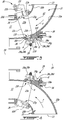
Fig. 3 is an enlarged view of a top portion ofFig. 2 ; and -
Fig. 4 is an enlarged view of a bottom portion ofFig. 2 . -
Fig. 1 illustrates a first example of a multi-spoolgas turbine engine 10 of a type preferably provided for use in subsonic flight, and generally comprising an engine core having a turbomachinery with multiple spools which perform compression to pressurize atmospheric air received through anair inlet 13, and which extract energy from combustion gases before they exit the engine via anexhaust outlet 17. The engine core further comprises acore gaspath 11 to direct gases from theair inlet 13 to theexhaust outlet 17. Thecore gaspath 11 is annular and extends around an enginecentral axis 19. In the embodiment shown, theengine 10 is a reverse-flow engine in that a direction of a flow F within thegaspath 11 corresponds to a direction of travel T of theengine 10. Other configurations are contemplated and the present disclosure may apply to other type of engines, such as, a turbofan engine. - The term "spool" is herein intended to broadly refer to drivingly connected turbine and compressor rotors and is, thus, not limited to a compressor and turbine assembly on a single shaft. It may include a rotary assembly with multiple shafts geared together.
- In the embodiment shown in
Fig. 1 , the engine core includes a low pressure (LP)spool 12 and a high pressure (HP)spool 14. TheLP spool 12 generally comprises anLP compressor 12a for pressurizing air received from theair inlet 13 and anLP turbine 12b for extracting energy from combustion gases discharged from acombustor 15 in which compressed air is mixed with fuel and ignited for generating an annular stream of hot combustion gases. TheLP turbine 12b is herein connected mechanically to theLP compressor 12a via aLP shaft 12c. Flow communication between the twoLP compressor 12a and thelow pressure turbine 12b is through thehigh pressure spool 14 and thecombustor 15 via thecore gaspath 11. According to one aspect of the embodiment shown inFig. 1 , theLP compressor 12a and theLP turbine 12b are coaxially mounted for rotation about thecentral axis 19 of theengine 10. - The HP spool 14 generally comprises an HP
compressor 14a connected in flow communication with theLP compressor 12a for receiving pressurized air therefrom via thecore gaspath 11. The HP spool 14 further comprises an HPturbine 14b, which is herein located immediately downstream of thecombustor 15. The HPturbine 14b is drivingly connected to the HPcompressor 14a via an HPshaft 14c. The HPshaft 14c is herein coaxial to the enginecentral axis 19. In the illustrated embodiment, theLP compressor 12a, theLP turbine 12b, the HPturbine 14b and the HPcompressor 14a are all mounted for rotation about the enginecentral axis 19. - In the embodiment shown, the
LP spool 12 is drivingly connected to an accessory gearbox (AGB) 18, includinggears 18a, that is rear mounted and drivingly connected to theLP pressure spool 12 via atorque shaft 12d engaged to theLP shaft 12c via a spline coupling. The AGB 18 is coaxially mounted at the rear end of theengine 10, and upstream of theLP compressor 12a, for providing drive outputs to various accessories (e.g. fuel pump, starter-generator, oil pump, scavenge pump, etc.). Alternatively, the AGB 18 is drivingly engaged to the HPspool 14 by having the HPshaft 14c extending axially beyond the HPcompressor 14a through a central bore of theLP compressor 12a to provide a drive input to the AGB 18. Other configurations are contemplated. - The
LP turbine 12b is also known as the power turbine. According to the illustrated embodiment, theLP turbine 12b drives a rotatable load R, such as a propeller, which provides thrust for flight and taxiing in aircraft applications. However, it is understood that theLP turbine 12b may drive a helicopter main rotor(s) and/or tail rotor(s), pump(s), generator(s), gas compressor(s), marine propeller(s), etc. - Referring to
Figs. 1-4 , in the embodiment shown, theengine 10 has a variable inlet guide vane (VIGV)assembly 20. TheVIGV assembly 20 includes a plurality ofinlet guide vanes 22, referred to herein below simply as "vanes". Thevanes 22 haveairfoil portions 22a extending across thegaspath 11 between aninner wall 10a and anouter wall 10b of theengine 10. Thesewalls vanes 22 are rotatable about pivot axes A to change an angle of attack of thevanes 22 relative to the flow F flowing within thegaspath 11. - In the embodiment shown, the
VIGV assembly 20 is located downstream of theinlet 13 of theengine 10 and upstream of theLP compressor 12a. However, any other suitable location is contemplated. It will be appreciated that although theVIGV assembly 20 is depicted as being located at an inlet section of theengine 10 upstream of theLP compressor 12, theVIGV assembly 20 may be located at any other suitable locations, such as downstream of thecombustor 15, between the LP andHP compressors HP turbines - Herein, the
inlet 13 of theengine 10 is defined by aninlet duct 21; theinlet duct 21 curving from being oriented substantially radially relative to the enginecentral axis 19 at theair inlet 13 to being oriented substantially axially upstream of theLP compressor 12a and downstream of thevanes 22. The inner andouter walls engine 10 defines theinlet duct 21 and curve from a substantially radial orientation at theinlet 13 to a substantially axial orientation upstream of theLP compressor 12a and downstream of theVIGV assembly 20. Herein, theVIGV assembly 20 is located within theinlet duct 21 at a location were the radii of both of the inner andouter walls gaspath 11. - Referring to
Figs. 3-4 , thevanes 22 have leading edges 22b andtrailing edges 22c spaced apart form the leading edges 22b by chords; both of the leading andtrailing edges 22b, 22c extending along a span of theairfoil portions 22a of thevanes 22. Thevanes 22 have opposed pressure and suction sides extending along the span and from the leading edges 22b to thetrailing edges 22c. - The
vanes 22 haveinner shaft portions 22d andouter shaft portions 22e protruding respectively from inner andouter ends airfoil portions 22a of thevanes 22. Theinner shaft portions 22d are pivotably received within correspondinglyshaped apertures 10c defined through theinner wall 10a.Bushings 24 are disposed around theinner shaft portions 22d to reduce friction between a peripheral wall of theapertures 10c defined in theinner wall 10a and theinner shaft portions 22d. It will be appreciated that any suitable type of bearings may be used. Bushings or other bearings may also be disposed around theouter shaft portions 22e. - In the depicted embodiment, guiding
members 26 are received withinapertures 10d defined through theouter wall 10b. These guidingmembers 26 bridge gaps between peripheral walls of theapertures 10d and theouter shaft portions 22e. This guidingmember 26 may assist the rotation of thevanes 22 relative to theouter wall 10d. Other configurations are contemplated and, in some cases, the guidingmember 26 may be omitted. The guidingmember 26 is a housing for theouter shaft protrusions 22e and acts as a portion of a wall delimiting the compressor gaspath. - As discussed above, the
vanes 22 are pivotable about their pivot axes A. TheVIGV assembly 20 includes amechanism 28 for coordinating pivot movements of thevanes 22. In the embodiment shown, themechanism 28 includesvane drive members 28a secured to theinner shaft portions 22d of thevanes 22. Thesemembers 28a can includegears 28b. In the embodiment shown, the gears are bevel gears. It will be appreciated that any other suitable drive transmission members may be used such as, for instance, fork and gear. Thevane drive members 28a are engaged with aunison transmission member 28c, which is, in the embodiment shown, aring gear 28d that extends circumferentially around thecentral axis 19 of theengine 10. As shown inFigs. 3-4 , thegears 28b secured to theinner shaft portions 22d of thevanes 22 are meshed with thering gear 28d. Herein, thevane drive members 28a are secured to theinner shaft portions 22d with nuts. Any suitable way to secured thevane drive members 28a theinner shaft portions 22d is contemplated including having thevanes 22 monolithically formed with themembers 28a. - It will be appreciated that, alternatively, the
unison transmission member 28c may be a annular ring and thevane drive members 28a may be a plurality of arms pivotably connected to the annular ring and fixedly mounted on theinner shaft portions 22d. Rotation of the annular ring changing angles defined between the arms and the annular ring thereby rotating the vanes about their pivot axes A. - The
unison transmission member 28c is radially supported by theinner wall 10a and is rotatable about the enginecentral axis 19 relative to theinner wall 10a. Since theunison transmission member 28c is engaged to thevane drive members 28a, rotation of theunison transmission member 28c about the enginecentral axis 19 translates into rotation of thevanes 22 about their respective pivot axes A. - Referring to
Figs. 2-4 , with use, wear and tear may occur on themembers ring gear mechanism 28 is located within a cavity C of theengine 10. Herein, the cavity C is defined by theaccessory gearbox 18. The cavity C is hydraulically connected to a lubricant source S, such as an oil source, for lubricating thegears 18a of theAGB 18. Consequently, themechanism 28 is exposed to a lubricated environment. This may increase a life span of the mechanism, more specifically, of thegears mechanism 28. Themechanism 28 may substantially be protected from an environment E outside theengine 10 by being contained with the lubricated cavity C of theAGB 18. A life span of the disclosedvane assembly 20 may be greater than that of a vane assembly in which components used to transmit rotation of the vanes are located outside a lubricated cavity. - It will be appreciated that the lubricated cavity C may be any suitable cavity and not necessarily the cavity C of the AGB. For instance, the
mechanism 28 may be located with a bearing cavity of theengine 10 that contains bearing radially supporting either one of the LP andHP shafts - In the embodiment shown, the
unison transmission member 28c is spaced apart from theinner wall 10a by a gap G. More specifically, theunison member 28c has anannular face 28g that faces theinner wall 10a; the gap G located between theannular face 28g and theinner wall 10a. In the present embodiment, theannular face 28g faces a direction that is solely radial and free of an axial component relative to thecentral axis 19. In a particular embodiment, having theannular face 28g facing a direction being solely radial and free of an axial component relative to thecentral axis 19 allows to minimize an axial play between thebevel gears 28b and thering gear 28d. This may lead to a better control of wear. The gap G is hydraulically connected tofluid passages 10e defined by theinner wall 10a. Thefluid passages 10e are hydraulically connected to the lubricant source S. As shown inFig. 2 , apump 34 is disposed within the cavity C and has an inlet hydraulically connected to the lubricant source S, either directly or via the cavity C, and an outlet hydraulically connected to thefluid passages 10e viasuitable conduits 36. Any suitable connection to bring lubricant from the lubricant source S to the gap G is contemplated. In the embodiment shown, theinner wall 10a defines apertures for receiving coupling ends of theconduits 36. Said apertures are hydraulically connected to the gap G via thefluid passages 10e. - Referring more particularly to
Fig. 3 , twoseals 28e are disposed between theinner wall 10a of theengine 10 and theunison member 28c. The twoseals 28e extend circumferentially around the enginecentral axis 19 and are spaced apart from one another and create a sealing engagement between theunison member 28c and theinner wall 10a to contain lubricant within the gap G. Herein, the twoseals 28e are ring seals received within correspondingly shaped grooves defined by theunion member 28c. Theseals 28e may alternatively be received with grooves defined in theinner wall 10a. As shown inFig. 3 , anoutlet 10f (Fig. 3 ) of thefluid passage 10e opens to the gap G, between the twoseals 28e. Theseals 28e may be ring seals, but any suitable seal may be used. Theseals 28e are biased between theunison member 28a and theinner wall 10a to create a sealing engagement therebetween. - Referring to
Fig. 3 , one of thevanes 22, referred to below as the master vane, includes adriving mechanism 30 that is engaged by an actuator 32 (Fig. 2 ) for rotating the master vane about its pivot axis A. In the embodiment shown, the master vane is the only vane that is engaged by an actuator. A remainder of thevanes 22 a slave vanes. Thedriving mechanism 30 is external to the cavity C. Rotation of the master vane translates into rotation of theunison transmission member 28c about the enginecentral axis 19 and in rotation of a remainder of thevanes 22, referred to as slave vanes, about their respective pivot axes A. - As shown in
Fig. 3 , thedriving mechanism 30 includes anexternal shaft portion 22h extending from theouter end 22g of the master vane and a lever 22i protruding at an angle from theexternal shaft portion 22h. The lever 22i is engaged to theactuator 32. Any suitable way of securing the lever 22i to theactuator 32 is contemplated. It will be appreciated that theactuator 32 can take various forms. For instance, it can be provided in the form of a linear actuator such as illustrated inFig. 2 , such as a piston and cylinder arrangement, operable to apply a tangential force to the lever 28i relative to the pivot axis A of themaster vane 22. - In the depicted embodiment, only a
single vane 22, the master vane, needs to be engaged by theactuator 32 to pivot all of thevanes 22 about their respective pivot axes A using themechanism 28 located inside the cavity C and, therefore, substantially exposed to lubricant. The injection of lubricant in the gap G may ensure that rotation of theunison member 28c about thecentral axis 19 and relative to theinner wall 10a is as low-friction as possible to limit an amount of force applied on the lever 22i of the master vane by theactuator 30. Lubricating the interface between theunison member 28c and theinner wall 10a and/or having themechanism 28 in a lubricated cavity C may increase a lifespan of thevane assembly 20, reduce wear and tear on the components of themechanism 28 compared to a configuration in which the components are external to a lubricated cavity. The disclosedvane assembly 20 may have an increased durability and may allow reducing maintenance costs. - Embodiments disclosed herein include:
- A. A variable guide vane (VGV) assembly, comprising: a casing enclosing a cavity hydraulically connectable to a lubrication system, the casing defining apertures circumferentially distributed around a central axis; variable guide vanes (VGVs) circumferentially distributed around the central axis, each VGVs having an airfoil portion extending from a first end to a second end along a pivot axis, and a shaft portion protruding from the first end and extending away from the airfoil portion and pivotably received within the apertures; vane drive members secured to respective ones of the shaft portion of the VGVs and located within the cavity, a unison transmission member within the cavity and rotatable about the central axis, the unison transmission member engaged to the vane drive members, and an external mechanism secured to the second end of one of the VGVs, the external mechanism disposed outside the cavity, the external mechanism engageable by an actuator for rotating the one of the VGVs about its pivot axis, thereby rotating the unison transmission member, which, in turn, drives a remainder of the VGVs in rotation.
- B. A gas turbine engine having a central axis, comprising a gaspath defined between an inner wall and an outer wall, a cavity located radially inwardly of the inner wall and hydraulically connected to a lubricant source, guide vanes circumferentially distributed around the central axis, the guide vanes having airfoil portions extending between the inner and outer walls across the gaspath and along pivot axes, the guide vanes having inner shaft portions protruding from the airfoil portions and pivotably received within apertures defined through the inner wall and outer shaft portions protruding from the airfoil portions and pivotably received within apertures defined through the outer wall, vane drive members secured to the inner shaft portions and located within the cavity, a unison transmission member radially supported by the inner wall within the cavity and rotatable relative the inner wall about the central axis, the unison transmission member engaged to the vane drive members, and an external mechanism secured to the outer shaft portion of one of the guide vanes, the external mechanism engaged to an actuator for rotating the one of the guide vanes about a respective pivot axis thereby rotating the unison transmission member about the central axis and rotating a remainder of the guide vanes about the pivot axes.
- Embodiments A and B may include any of the following elements, in any combinations:
Element 1: the vane drive members are vane gears and the unison transmission member is a unison gear meshed with the vane gears. Element 2: the vane gears are bevel gears. Element 3: the external mechanism includes an external shaft portion extending from the second end of the airfoil portion of the one of the VGVs and a lever protruding from the external shaft portion, the lever engageable to the actuator. Element 4: the unison transmission member is spaced apart from the casing by a gap, the gap hydraulically connected to a fluid passage defined by the casing, the fluid passage hydraulically connectable to a lubricant source. Element 5: two spaced-apart seals biased between the unison transmission member and the casing, the fluid passage having an outlet opening to the gap between the two spaced-apart seals. Element 6: the unison transmission member has an annular face facing the inner wall, the gap between the annular face and the inner wall, the annular face facing a direction free of an axial component relative to the central axis. Element 7: the second ends of the VGVs are located radially outwardly of the first ends relative to the central axis. Element 8: a radius of a portion of the casing decreases in a direction of a flow flowing between the vanes, the apertures located at the portion of the casing. Element 9: a shaft rotatable about the central axis and an accessory gearbox in driving engagement with the shaft, the accessory gearbox contained within the cavity. Element 10: the accessory gearbox is located upstream of a compressor section of the gas turbine engine relative to a flow in the gaspath, the guide vanes located upstream of the compressor section. Element 11: the gas turbine engine is a reverse-flow gas turbine engine comprising an output shaft for driving a rotatable load, the output shaft and accessory gearbox located at opposite ends of the gas turbine engine. Element 12: a direction of the flow within the gas path corresponds to a direction of travel of the gas turbine engine. Element 13: a radius of a portion of the inner wall decreases in a direction of a flow in the gaspath, the apertures defined through the inner wall located at the portion of the casing. Element 14: the vane drive members are vane gears and the unison transmission member is a unison gear meshed with the vane gears. Element 15: the external mechanism includes a lever protruding radially from the outer shaft portion of the one of the guide vanes, the lever engaged to the actuator. Element 16: the actuator is a linear actuator. Element 17: the unison transmission member is spaced apart from the inner wall by a gap, the gap hydraulically connected to a fluid passage defined by the inner wall, the fluid passage hydraulically connected to the lubricant source. Element 18: two spaced-apart seals located between the unison transmission member and the inner wall, the fluid passage having an outlet opening to the gap between the two spaced-apart seals. - The embodiments described in this document provide non-limiting examples of possible implementations of the present technology. Upon review of the present disclosure, a person of ordinary skill in the art will recognize that changes may be made to the embodiments described herein without departing from the scope of the present technology. For example, the lubricated cavity may be annular and extend circumferentially around the engine central axis and located radially outwardly of the outer wall of the engine. In such a case, the gears would be secured to the outer shaft portions of the vanes and the actuator would be located radially inwardly of the inner wall. Yet further modifications could be implemented by a person of ordinary skill in the art in view of the present disclosure, which modifications would be within the scope of the present technology.
Claims (15)
- A variable guide vane (VGV) assembly (20), comprising: a casing enclosing a cavity (C) hydraulically connectable to a lubrication system, the casing defining apertures (10c, 10d) circumferentially distributed around a central axis (19); variable guide vanes (VGVs) (22) circumferentially distributed around the central axis (19), each VGVs (22) having an airfoil portion (22a) extending from a first end (22f) to a second end (22g) along a pivot axis (A), and a shaft portion (22d) protruding from the first end (22f) and extending away from the airfoil portion (22a) and pivotably received within the apertures (10c, 10d); vane drive members (28a) secured to respective ones of the shaft portion (22d) of the VGVs (22) and located within the cavity (C), a unison transmission member (28c) within the cavity (C) and rotatable about the central axis (19), the unison transmission member (28c) engaged to the vane drive members (28a), and an external mechanism (30) secured to the second end of one of the VGVs (22), the external mechanism (30) disposed outside the cavity (C), the external mechanism (30) engageable by an actuator (32) for rotating the one of the VGVs (22) about its pivot axis (A), thereby rotating the unison transmission member (28c), which, in turn, drives a remainder of the VGVs (22) in rotation.
- The VGV assembly (20) of claim 1, wherein the vane drive members (28a) are vane gears (28b) and the unison transmission member (28c) is a unison gear meshed with the vane gears (28b).
- The VGV assembly (20) of claim 2, wherein the vane gears (28b) are bevel gears.
- The VGV assembly (20) of any of claims 1 to 3, wherein the external mechanism (30) includes an external shaft portion (22h) extending from the second end (22g) of the airfoil portion (22a) of the one of the VGVs (22) and a lever (22i) protruding from the external shaft portion (22h), the lever (22i) engageable to the actuator (32).
- The VGV assembly (20) of any preceding claim, wherein the unison transmission member (28c) is spaced apart from the casing by a gap (G), the gap (G) hydraulically connected to a fluid passage (10e) defined by the casing, the fluid passage (10e) hydraulically connectable to a lubricant source (S).
- The VGV assembly (20) of claim 5, comprising two spaced-apart seals (28e) biased between the unison transmission member (28c) and the casing, the fluid passage (10e) having an outlet (10f) opening to the gap (G) between the two spaced-apart seals (28e).
- The VGV assembly (20) of claim 5 or 6, wherein the unison transmission member (28c) has an annular face (28g) facing the inner wall (10a), the gap (G) between the annular face (28g) and the inner wall (10a), the annular face (28g) facing a direction free of an axial component relative to the central axis (19).
- The VGV assembly (20) of any preceding claim, wherein the second ends (22g) of the VGVs (22) are located radially outwardly of the first ends (22f) relative to the central axis (19).
- The VGV assembly (20) of any preceding claim, wherein a radius of a portion of the casing decreases in a direction of a flow flowing between the vanes (22), the apertures (10c, 10d) located at the portion of the casing.
- A gas turbine engine (10) comprising the VGV assembly (20) according to any preceding claim, the gas turbine engine (10) having a gaspath (11) defined between an inner wall (10a) and an outer wall (10b), the cavity (C) located radially inwardly of the inner wall (10a) and hydraulically connected to a lubricant source (S), the airfoil portions (22a) extending between the inner and outer walls (10a, 10b) across the gaspath (11).
- The gas turbine engine (10) of claim 10, comprising a shaft (12d) rotatable about the central axis (19) and an accessory gearbox (18) in driving engagement with the shaft (12d), the accessory gearbox (18) contained within the cavity (C).
- The gas turbine engine (10) of claim 11, wherein the accessory gearbox (18) is located upstream of a compressor section of the gas turbine engine (10) relative to a flow in the gaspath (11), the variable guide vanes (22) located upstream of the compressor section.
- The gas turbine engine (10) of claim 11 or 12, wherein the gas turbine engine (10) is a reverse-flow gas turbine engine (10) comprising an output shaft for driving a rotatable load (R), the output shaft and accessory gearbox (18) located at opposite ends of the gas turbine engine (10).
- The gas turbine engine (10) of any of claims 10 to 13, wherein a direction of the flow within the gas path (11) corresponds to a direction of travel (T) of the gas turbine engine (10).
- The gas turbine engine (10) of any of claims 10 to 14, wherein a radius of a portion of the inner wall (10a) decreases in a direction of a flow in the gaspath (11), the apertures (10c, 10d) defined through the inner wall (10a) located at the portion of the casing.
Applications Claiming Priority (1)
| Application Number | Priority Date | Filing Date | Title |
|---|---|---|---|
| US16/885,846 US11346241B2 (en) | 2020-05-28 | 2020-05-28 | Variable guide vanes assembly |
Publications (2)
| Publication Number | Publication Date |
|---|---|
| EP3916202A1 true EP3916202A1 (en) | 2021-12-01 |
| EP3916202B1 EP3916202B1 (en) | 2023-01-18 |
Family
ID=76522760
Family Applications (1)
| Application Number | Title | Priority Date | Filing Date |
|---|---|---|---|
| EP21176746.2A Active EP3916202B1 (en) | 2020-05-28 | 2021-05-28 | Variable guide vanes assembly |
Country Status (3)
| Country | Link |
|---|---|
| US (1) | US11346241B2 (en) |
| EP (1) | EP3916202B1 (en) |
| CA (1) | CA3117181A1 (en) |
Families Citing this family (1)
| Publication number | Priority date | Publication date | Assignee | Title |
|---|---|---|---|---|
| US11965422B2 (en) | 2022-08-02 | 2024-04-23 | Pratt & Whitney Canada Corp. | Variable guide vane assembly for gas turbine engine |
Citations (3)
| Publication number | Priority date | Publication date | Assignee | Title |
|---|---|---|---|---|
| US2805818A (en) * | 1951-12-13 | 1957-09-10 | Ferri Antonio | Stator for axial flow compressor with supersonic velocity at entrance |
| WO1990002256A1 (en) * | 1988-08-17 | 1990-03-08 | Sundstrand Corporation | Guide vane assembly for auxiliary power unit |
| US9784365B2 (en) * | 2014-01-23 | 2017-10-10 | Pratt & Whitney Canada Corp. | Variable vane actuating system |
Family Cites Families (7)
| Publication number | Priority date | Publication date | Assignee | Title |
|---|---|---|---|---|
| GB1067930A (en) * | 1965-12-29 | 1967-05-10 | Rolls Royce | Vane operating mechanism for fluid flow machines |
| US3850544A (en) * | 1973-11-02 | 1974-11-26 | Gen Electric | Mounting arrangement for a bearing of axial flow turbomachinery having variable pitch stationary blades |
| US8894361B2 (en) * | 2011-08-30 | 2014-11-25 | Siemens Energy, Inc. | Gas turbine compressor inlet with reduced flow distortion |
| US8863491B2 (en) | 2012-01-31 | 2014-10-21 | United Technologies Corporation | Gas turbine engine shaft bearing configuration |
| JP6185781B2 (en) * | 2013-07-23 | 2017-08-23 | 三菱日立パワーシステムズ株式会社 | Axial flow compressor |
| EP3333082B1 (en) * | 2016-12-12 | 2020-06-17 | Ge Avio S.r.l. | Thrust measuring device for a propulsion system |
| FR3082896B1 (en) | 2018-06-22 | 2021-06-04 | Safran Aircraft Engines | KIT FOR THE CONTROL OF VARIABLE TIMING BLADES |
-
2020
- 2020-05-28 US US16/885,846 patent/US11346241B2/en active Active
-
2021
- 2021-05-04 CA CA3117181A patent/CA3117181A1/en active Pending
- 2021-05-28 EP EP21176746.2A patent/EP3916202B1/en active Active
Patent Citations (3)
| Publication number | Priority date | Publication date | Assignee | Title |
|---|---|---|---|---|
| US2805818A (en) * | 1951-12-13 | 1957-09-10 | Ferri Antonio | Stator for axial flow compressor with supersonic velocity at entrance |
| WO1990002256A1 (en) * | 1988-08-17 | 1990-03-08 | Sundstrand Corporation | Guide vane assembly for auxiliary power unit |
| US9784365B2 (en) * | 2014-01-23 | 2017-10-10 | Pratt & Whitney Canada Corp. | Variable vane actuating system |
Also Published As
| Publication number | Publication date |
|---|---|
| CA3117181A1 (en) | 2021-11-28 |
| US20210372292A1 (en) | 2021-12-02 |
| EP3916202B1 (en) | 2023-01-18 |
| US11346241B2 (en) | 2022-05-31 |
Similar Documents
| Publication | Publication Date | Title |
|---|---|---|
| US10767567B2 (en) | Multi-spool gas turbine engine architecture | |
| US11408352B2 (en) | Reverse-flow gas turbine engine | |
| EP3597884B1 (en) | A multi-spool gas turbine engine architecture | |
| EP3361057B1 (en) | Turbine with low over-speed requirements and method | |
| EP3339610B1 (en) | Multi-spool gas turbine engine architecture | |
| CA2970386C (en) | A multi-spool gas turbine engine architecture | |
| EP3859133B1 (en) | Gas turbine engine with clutch system | |
| EP3321488B1 (en) | Gas turbine engine accessories arrangement | |
| EP3354876B1 (en) | Gas turbine engine architecture with split compressor system | |
| US12460550B2 (en) | Fan module equipped with an oil transfer device | |
| EP3916202B1 (en) | Variable guide vanes assembly | |
| US4932206A (en) | Guide vane assembly for auxiliary power unit | |
| CN120444408A (en) | Gearbox assembly with gear braking system | |
| CN119222048A (en) | Lubrication systems for gear assemblies |
Legal Events
| Date | Code | Title | Description |
|---|---|---|---|
| PUAI | Public reference made under article 153(3) epc to a published international application that has entered the european phase |
Free format text: ORIGINAL CODE: 0009012 |
|
| STAA | Information on the status of an ep patent application or granted ep patent |
Free format text: STATUS: THE APPLICATION HAS BEEN PUBLISHED |
|
| AK | Designated contracting states |
Kind code of ref document: A1 Designated state(s): AL AT BE BG CH CY CZ DE DK EE ES FI FR GB GR HR HU IE IS IT LI LT LU LV MC MK MT NL NO PL PT RO RS SE SI SK SM TR |
|
| B565 | Issuance of search results under rule 164(2) epc |
Effective date: 20211103 |
|
| STAA | Information on the status of an ep patent application or granted ep patent |
Free format text: STATUS: REQUEST FOR EXAMINATION WAS MADE |
|
| 17P | Request for examination filed |
Effective date: 20220318 |
|
| RBV | Designated contracting states (corrected) |
Designated state(s): AL AT BE BG CH CY CZ DE DK EE ES FI FR GB GR HR HU IE IS IT LI LT LU LV MC MK MT NL NO PL PT RO RS SE SI SK SM TR |
|
| GRAP | Despatch of communication of intention to grant a patent |
Free format text: ORIGINAL CODE: EPIDOSNIGR1 |
|
| STAA | Information on the status of an ep patent application or granted ep patent |
Free format text: STATUS: GRANT OF PATENT IS INTENDED |
|
| RIC1 | Information provided on ipc code assigned before grant |
Ipc: F04D 29/56 20060101ALI20220627BHEP Ipc: F04D 27/02 20060101ALI20220627BHEP Ipc: F01D 17/16 20060101ALI20220627BHEP Ipc: F01D 9/06 20060101AFI20220627BHEP |
|
| INTG | Intention to grant announced |
Effective date: 20220802 |
|
| GRAS | Grant fee paid |
Free format text: ORIGINAL CODE: EPIDOSNIGR3 |
|
| GRAA | (expected) grant |
Free format text: ORIGINAL CODE: 0009210 |
|
| STAA | Information on the status of an ep patent application or granted ep patent |
Free format text: STATUS: THE PATENT HAS BEEN GRANTED |
|
| AK | Designated contracting states |
Kind code of ref document: B1 Designated state(s): AL AT BE BG CH CY CZ DE DK EE ES FI FR GB GR HR HU IE IS IT LI LT LU LV MC MK MT NL NO PL PT RO RS SE SI SK SM TR |
|
| REG | Reference to a national code |
Ref country code: GB Ref legal event code: FG4D |
|
| REG | Reference to a national code |
Ref country code: DE Ref legal event code: R096 Ref document number: 602021001254 Country of ref document: DE |
|
| REG | Reference to a national code |
Ref country code: CH Ref legal event code: EP |
|
| REG | Reference to a national code |
Ref country code: AT Ref legal event code: REF Ref document number: 1544826 Country of ref document: AT Kind code of ref document: T Effective date: 20230215 Ref country code: IE Ref legal event code: FG4D |
|
| REG | Reference to a national code |
Ref country code: LT Ref legal event code: MG9D |
|
| REG | Reference to a national code |
Ref country code: NL Ref legal event code: MP Effective date: 20230118 |
|
| REG | Reference to a national code |
Ref country code: AT Ref legal event code: MK05 Ref document number: 1544826 Country of ref document: AT Kind code of ref document: T Effective date: 20230118 |
|
| PG25 | Lapsed in a contracting state [announced via postgrant information from national office to epo] |
Ref country code: NL Free format text: LAPSE BECAUSE OF FAILURE TO SUBMIT A TRANSLATION OF THE DESCRIPTION OR TO PAY THE FEE WITHIN THE PRESCRIBED TIME-LIMIT Effective date: 20230118 |
|
| P01 | Opt-out of the competence of the unified patent court (upc) registered |
Effective date: 20230530 |
|
| PG25 | Lapsed in a contracting state [announced via postgrant information from national office to epo] |
Ref country code: RS Free format text: LAPSE BECAUSE OF FAILURE TO SUBMIT A TRANSLATION OF THE DESCRIPTION OR TO PAY THE FEE WITHIN THE PRESCRIBED TIME-LIMIT Effective date: 20230118 Ref country code: PT Free format text: LAPSE BECAUSE OF FAILURE TO SUBMIT A TRANSLATION OF THE DESCRIPTION OR TO PAY THE FEE WITHIN THE PRESCRIBED TIME-LIMIT Effective date: 20230518 Ref country code: NO Free format text: LAPSE BECAUSE OF FAILURE TO SUBMIT A TRANSLATION OF THE DESCRIPTION OR TO PAY THE FEE WITHIN THE PRESCRIBED TIME-LIMIT Effective date: 20230418 Ref country code: LV Free format text: LAPSE BECAUSE OF FAILURE TO SUBMIT A TRANSLATION OF THE DESCRIPTION OR TO PAY THE FEE WITHIN THE PRESCRIBED TIME-LIMIT Effective date: 20230118 Ref country code: LT Free format text: LAPSE BECAUSE OF FAILURE TO SUBMIT A TRANSLATION OF THE DESCRIPTION OR TO PAY THE FEE WITHIN THE PRESCRIBED TIME-LIMIT Effective date: 20230118 Ref country code: HR Free format text: LAPSE BECAUSE OF FAILURE TO SUBMIT A TRANSLATION OF THE DESCRIPTION OR TO PAY THE FEE WITHIN THE PRESCRIBED TIME-LIMIT Effective date: 20230118 Ref country code: ES Free format text: LAPSE BECAUSE OF FAILURE TO SUBMIT A TRANSLATION OF THE DESCRIPTION OR TO PAY THE FEE WITHIN THE PRESCRIBED TIME-LIMIT Effective date: 20230118 Ref country code: AT Free format text: LAPSE BECAUSE OF FAILURE TO SUBMIT A TRANSLATION OF THE DESCRIPTION OR TO PAY THE FEE WITHIN THE PRESCRIBED TIME-LIMIT Effective date: 20230118 |
|
| PG25 | Lapsed in a contracting state [announced via postgrant information from national office to epo] |
Ref country code: SE Free format text: LAPSE BECAUSE OF FAILURE TO SUBMIT A TRANSLATION OF THE DESCRIPTION OR TO PAY THE FEE WITHIN THE PRESCRIBED TIME-LIMIT Effective date: 20230118 Ref country code: PL Free format text: LAPSE BECAUSE OF FAILURE TO SUBMIT A TRANSLATION OF THE DESCRIPTION OR TO PAY THE FEE WITHIN THE PRESCRIBED TIME-LIMIT Effective date: 20230118 Ref country code: IS Free format text: LAPSE BECAUSE OF FAILURE TO SUBMIT A TRANSLATION OF THE DESCRIPTION OR TO PAY THE FEE WITHIN THE PRESCRIBED TIME-LIMIT Effective date: 20230518 Ref country code: GR Free format text: LAPSE BECAUSE OF FAILURE TO SUBMIT A TRANSLATION OF THE DESCRIPTION OR TO PAY THE FEE WITHIN THE PRESCRIBED TIME-LIMIT Effective date: 20230419 Ref country code: FI Free format text: LAPSE BECAUSE OF FAILURE TO SUBMIT A TRANSLATION OF THE DESCRIPTION OR TO PAY THE FEE WITHIN THE PRESCRIBED TIME-LIMIT Effective date: 20230118 |
|
| REG | Reference to a national code |
Ref country code: DE Ref legal event code: R097 Ref document number: 602021001254 Country of ref document: DE |
|
| PG25 | Lapsed in a contracting state [announced via postgrant information from national office to epo] |
Ref country code: SM Free format text: LAPSE BECAUSE OF FAILURE TO SUBMIT A TRANSLATION OF THE DESCRIPTION OR TO PAY THE FEE WITHIN THE PRESCRIBED TIME-LIMIT Effective date: 20230118 Ref country code: RO Free format text: LAPSE BECAUSE OF FAILURE TO SUBMIT A TRANSLATION OF THE DESCRIPTION OR TO PAY THE FEE WITHIN THE PRESCRIBED TIME-LIMIT Effective date: 20230118 Ref country code: EE Free format text: LAPSE BECAUSE OF FAILURE TO SUBMIT A TRANSLATION OF THE DESCRIPTION OR TO PAY THE FEE WITHIN THE PRESCRIBED TIME-LIMIT Effective date: 20230118 Ref country code: DK Free format text: LAPSE BECAUSE OF FAILURE TO SUBMIT A TRANSLATION OF THE DESCRIPTION OR TO PAY THE FEE WITHIN THE PRESCRIBED TIME-LIMIT Effective date: 20230118 Ref country code: CZ Free format text: LAPSE BECAUSE OF FAILURE TO SUBMIT A TRANSLATION OF THE DESCRIPTION OR TO PAY THE FEE WITHIN THE PRESCRIBED TIME-LIMIT Effective date: 20230118 |
|
| PLBE | No opposition filed within time limit |
Free format text: ORIGINAL CODE: 0009261 |
|
| STAA | Information on the status of an ep patent application or granted ep patent |
Free format text: STATUS: NO OPPOSITION FILED WITHIN TIME LIMIT |
|
| PG25 | Lapsed in a contracting state [announced via postgrant information from national office to epo] |
Ref country code: SK Free format text: LAPSE BECAUSE OF FAILURE TO SUBMIT A TRANSLATION OF THE DESCRIPTION OR TO PAY THE FEE WITHIN THE PRESCRIBED TIME-LIMIT Effective date: 20230118 |
|
| 26N | No opposition filed |
Effective date: 20231019 |
|
| PG25 | Lapsed in a contracting state [announced via postgrant information from national office to epo] |
Ref country code: MC Free format text: LAPSE BECAUSE OF FAILURE TO SUBMIT A TRANSLATION OF THE DESCRIPTION OR TO PAY THE FEE WITHIN THE PRESCRIBED TIME-LIMIT Effective date: 20230118 |
|
| REG | Reference to a national code |
Ref country code: BE Ref legal event code: MM Effective date: 20230531 |
|
| PG25 | Lapsed in a contracting state [announced via postgrant information from national office to epo] |
Ref country code: SI Free format text: LAPSE BECAUSE OF FAILURE TO SUBMIT A TRANSLATION OF THE DESCRIPTION OR TO PAY THE FEE WITHIN THE PRESCRIBED TIME-LIMIT Effective date: 20230118 Ref country code: MC Free format text: LAPSE BECAUSE OF FAILURE TO SUBMIT A TRANSLATION OF THE DESCRIPTION OR TO PAY THE FEE WITHIN THE PRESCRIBED TIME-LIMIT Effective date: 20230118 Ref country code: LU Free format text: LAPSE BECAUSE OF NON-PAYMENT OF DUE FEES Effective date: 20230528 |
|
| REG | Reference to a national code |
Ref country code: IE Ref legal event code: MM4A |
|
| PG25 | Lapsed in a contracting state [announced via postgrant information from national office to epo] |
Ref country code: IE Free format text: LAPSE BECAUSE OF NON-PAYMENT OF DUE FEES Effective date: 20230528 |
|
| PG25 | Lapsed in a contracting state [announced via postgrant information from national office to epo] |
Ref country code: IE Free format text: LAPSE BECAUSE OF NON-PAYMENT OF DUE FEES Effective date: 20230528 |
|
| PG25 | Lapsed in a contracting state [announced via postgrant information from national office to epo] |
Ref country code: IT Free format text: LAPSE BECAUSE OF FAILURE TO SUBMIT A TRANSLATION OF THE DESCRIPTION OR TO PAY THE FEE WITHIN THE PRESCRIBED TIME-LIMIT Effective date: 20230118 Ref country code: BE Free format text: LAPSE BECAUSE OF NON-PAYMENT OF DUE FEES Effective date: 20230531 |
|
| PG25 | Lapsed in a contracting state [announced via postgrant information from national office to epo] |
Ref country code: BG Free format text: LAPSE BECAUSE OF FAILURE TO SUBMIT A TRANSLATION OF THE DESCRIPTION OR TO PAY THE FEE WITHIN THE PRESCRIBED TIME-LIMIT Effective date: 20230118 |
|
| PG25 | Lapsed in a contracting state [announced via postgrant information from national office to epo] |
Ref country code: BG Free format text: LAPSE BECAUSE OF FAILURE TO SUBMIT A TRANSLATION OF THE DESCRIPTION OR TO PAY THE FEE WITHIN THE PRESCRIBED TIME-LIMIT Effective date: 20230118 |
|
| REG | Reference to a national code |
Ref country code: CH Ref legal event code: PL |
|
| PG25 | Lapsed in a contracting state [announced via postgrant information from national office to epo] |
Ref country code: CH Free format text: LAPSE BECAUSE OF NON-PAYMENT OF DUE FEES Effective date: 20240531 |
|
| PGFP | Annual fee paid to national office [announced via postgrant information from national office to epo] |
Ref country code: DE Payment date: 20250423 Year of fee payment: 5 |
|
| PGFP | Annual fee paid to national office [announced via postgrant information from national office to epo] |
Ref country code: GB Payment date: 20250423 Year of fee payment: 5 |
|
| PGFP | Annual fee paid to national office [announced via postgrant information from national office to epo] |
Ref country code: FR Payment date: 20250423 Year of fee payment: 5 |
|
| PG25 | Lapsed in a contracting state [announced via postgrant information from national office to epo] |
Ref country code: CY Free format text: LAPSE BECAUSE OF FAILURE TO SUBMIT A TRANSLATION OF THE DESCRIPTION OR TO PAY THE FEE WITHIN THE PRESCRIBED TIME-LIMIT; INVALID AB INITIO Effective date: 20210528 |
|
| PG25 | Lapsed in a contracting state [announced via postgrant information from national office to epo] |
Ref country code: TR Free format text: LAPSE BECAUSE OF FAILURE TO SUBMIT A TRANSLATION OF THE DESCRIPTION OR TO PAY THE FEE WITHIN THE PRESCRIBED TIME-LIMIT Effective date: 20230118 |
|
| PG25 | Lapsed in a contracting state [announced via postgrant information from national office to epo] |
Ref country code: HU Free format text: LAPSE BECAUSE OF FAILURE TO SUBMIT A TRANSLATION OF THE DESCRIPTION OR TO PAY THE FEE WITHIN THE PRESCRIBED TIME-LIMIT; INVALID AB INITIO Effective date: 20210528 |