EP3916152A1 - Switch for track of maglev train - Google Patents
Switch for track of maglev train Download PDFInfo
- Publication number
- EP3916152A1 EP3916152A1 EP19912160.9A EP19912160A EP3916152A1 EP 3916152 A1 EP3916152 A1 EP 3916152A1 EP 19912160 A EP19912160 A EP 19912160A EP 3916152 A1 EP3916152 A1 EP 3916152A1
- Authority
- EP
- European Patent Office
- Prior art keywords
- track
- switch
- maglev train
- track beam
- bend
- Prior art date
- Legal status (The legal status is an assumption and is not a legal conclusion. Google has not performed a legal analysis and makes no representation as to the accuracy of the status listed.)
- Granted
Links
Images


Classifications
-
- E—FIXED CONSTRUCTIONS
- E01—CONSTRUCTION OF ROADS, RAILWAYS, OR BRIDGES
- E01B—PERMANENT WAY; PERMANENT-WAY TOOLS; MACHINES FOR MAKING RAILWAYS OF ALL KINDS
- E01B25/00—Tracks for special kinds of railways
- E01B25/30—Tracks for magnetic suspension or levitation vehicles
- E01B25/34—Switches; Frogs; Crossings
-
- E—FIXED CONSTRUCTIONS
- E01—CONSTRUCTION OF ROADS, RAILWAYS, OR BRIDGES
- E01B—PERMANENT WAY; PERMANENT-WAY TOOLS; MACHINES FOR MAKING RAILWAYS OF ALL KINDS
- E01B25/00—Tracks for special kinds of railways
- E01B25/08—Tracks for mono-rails with centre of gravity of vehicle above the load-bearing rail
- E01B25/12—Switches; Crossings
-
- E—FIXED CONSTRUCTIONS
- E01—CONSTRUCTION OF ROADS, RAILWAYS, OR BRIDGES
- E01B—PERMANENT WAY; PERMANENT-WAY TOOLS; MACHINES FOR MAKING RAILWAYS OF ALL KINDS
- E01B2202/00—Characteristics of moving parts of rail systems, e.g. switches, special frogs, tongues
- E01B2202/02—Nature of the movement
- E01B2202/025—Pure translation
-
- E—FIXED CONSTRUCTIONS
- E01—CONSTRUCTION OF ROADS, RAILWAYS, OR BRIDGES
- E01B—PERMANENT WAY; PERMANENT-WAY TOOLS; MACHINES FOR MAKING RAILWAYS OF ALL KINDS
- E01B2202/00—Characteristics of moving parts of rail systems, e.g. switches, special frogs, tongues
- E01B2202/02—Nature of the movement
- E01B2202/027—Including a component perpendicular to the plane of the rails
-
- E—FIXED CONSTRUCTIONS
- E01—CONSTRUCTION OF ROADS, RAILWAYS, OR BRIDGES
- E01B—PERMANENT WAY; PERMANENT-WAY TOOLS; MACHINES FOR MAKING RAILWAYS OF ALL KINDS
- E01B2202/00—Characteristics of moving parts of rail systems, e.g. switches, special frogs, tongues
- E01B2202/04—Nature of the support or bearing
- E01B2202/044—Rolling
- E01B2202/048—Rolling with rolls on moving part
Definitions
- the present application relates to the technical field of maglev trains, and in particular to a switch for a track of a maglev train.
- maglev train has been attracting attention because it almost has no friction resistance.
- the maglev train maintains suspension, travels forward and makes a turn depending on electromagnets on two sides of the track, thus, the train body needs to envelop the lower on two side of the track.
- the function of the switch is particularly important.
- a common switch for the track of the maglev train has the mechanical structure of forced elastic deformation, which has a large driving mass and a long track switching time.
- a switch for a track of a maglev train which includes a front main track beam and a rear switching track beam, and the rear switching track beam includes a central fixed track beam and a middle movable track beam;
- a switch for a track of a maglev train which includes a front main track beam and a rear switching track beam, and the rear switching track beam includes a central fixed track beam and a middle movable track beam;
- the central fixed track beam includes a first outer side beam for connecting the front main track beam with the bend track and a second outer side beam for connecting the front main track beam with the straight track.
- the first outer side beam and the second outer side beam are fixed track beams.
- the central mobile track beam is approximately a U-shaped similar track beam.
- the central mobile track beam includes a lateral beam and a first inner side beam and a second inner side beam that are respectively provided on two ends of the lateral beam.
- a roller is provided on the bottom of the lateral beam, so that the middle movable track beam can move between the first outer side beam and the second outer side beam of the central fixed track beam.
- the switch for the track of the maglev train further includes a bearing track provided at the bottom of the lateral beam and matched with the roller.
- the front main track beam is a cement or steel beam.
- the central fixed track beam is a fixed cement or steel beam.
- the middle movable track beam is the cement or steel beam.
- the switch for the track of the maglev train provided according to the present application has the following beneficial effects that the switch minimizes the forced deformation length by providing the middle movable track beam, the driving mass is minor, and the required track switching time is shortened.
- orientation or positional relationships indicated by terms “center”, “longitudinal”, “lateral”, “length”, “width”, “thickness”, “up”, “down”, “front”, “rear”, “left”, “right”, “vertical”, “horizontal”, “top”, “bottom”, “inner”, “outer”, “clockwise”, “anticlockwise” and the like are based on the orientation or positional relationships shown in the drawings, and are merely for the convenience of describing the present application and the simplification of the description, and do not indicate or imply that the device or member referred to must be in a particular orientation, or be constructed and operated in a particular orientation, and therefore should not be construed as a limitation to the scope of the present application.
- first”, “second” and the like are for purpose of description, and should not be interpreted as indicating or implying relative importance or implying the number of the indicated technical features.
- the features defined by “first”, “second” and the like can express or impliedly include one or more the features.
- the meaning of “multiple or a plurality of' is two or more, unless otherwise specifically defined.
- a core of the present application is to provide a switch for a track of a maglev train.
- the switch can minimize the switch movement and the forced deformation length, and the driving mass thereof is minor, and the required track switching time is shortened.
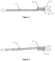
- Figure 1 is a schematic structural view of a switch for a track of a maglev train according to a specific embodiment of the present application in a straight track state
- Figure 2 is a schematic structural view of the switch for the track of the maglev train according to a specific embodiment of the present application in a bend track state
- Figure 3 is a schematic structural view of a central fixed track beam according to a specific embodiment of the present application
- Figure 4 is a schematic structural view of a middle movable track beam according to a specific embodiment of the present application
- Figure 5 is a side view (located at a bend track 6 position) of a rear switching track beam according to a specific embodiment of the present application
- Figure 6 is a side view (located at a bend track 6 position and a maglev train 5 is shown) of the rear switching track beam according to a specific embodiment of the present application
- Figure 7 is a side view (located at a straight track 7 position and the maglev train 5 is shown) of the rear switching track beam according to a specific embodiment of
- the switch for the track of the maglev train is provided according to the present application, as shown in Figures 1 to 4 .
- the switch includes a front main track beam 1 and a rear switching track beam.
- the rear switching track beam includes a central fixed track beam 2 and a middle movable track beam 3.
- the front main track beam 1 can rotate or switch between a straight track 7 and a bend track 6 by bending
- the central fixed track beam 2 is a fixed track beam
- the middle movable track beam 3 may move parallelly between the straight track 7 and the bend track 6.
- the switch for the track of the maglev train is provided according to the present application, as shown in Figures 5 to 7 .
- the central fixed track beam 2 includes a first outer side beam 21 for connecting the front main track beam 1 with the bend track 6 and a second outer side beam 22 for connecting the front main track beam 1 with the straight track 7.
- the first outer side beam 21 and the second outer side beam 22 are fixed track beams.
- the switch for the track of the maglev train is provided according to the present application
- the middle movable track beam 3 is approximately a U-shaped track beam.
- the central mobile track beam 3 includes a lateral beam 33 and a first inner side beam 31 and a second inner side beam 32 that are respectively provided on two ends of the lateral beam.
- a roller 34 is provided at the bottom of the lateral beam 33, so that the middle movable track beam 3 may move between the first outer side beam 21 and the second outer side beam 22 of the central fixed track beam 2.
- the switch for the track of the maglev train is provided according to the present application, as shown in Figure 6 .
- the middle movable track beam 3 moves to a position close to the first outer side beam 21, the first outer side beam 21 and the first inner side beam 31 are combined to form a transition beam for the maglev train 5 to pass through the bend track 6.
- the middle movable track beam 3 moves to a position close to the second outer side beam 22, the second outer side beam 22 and the second inner side beam 32 are combined to form a transition beam for the maglev train 5 to pass through the straight track 7.
- the switch for the track of the maglev train provided according to the present application further includes a bearing track 4 provided at the bottom of the lateral beam 33 and configured to cooperate with the roller 34.
- the roller 34 moves on the bearing track 4, so as to achieve the switching of the middle movable track beam 3 between the bend track 6 and the straight track 7.
- the switch for the track of the maglev train is provided according to the present application
- the front main track beam 1 and the middle movable track beam 3 are cements or steel beams.
- the central fixed track beam 2 is a fixed cement or steel beam.
- the switch for the track of the maglev train is provided according to the present application, as shown in Figures 5 and 6 , when the maglev train 5 travels on the bend track 6, the front main track beam 1 rotates around a rotation axis or bends to the bend track 6, and the middle movable track beam 3 parallelly moves to a position close to the first outer side beam 21.
- the front main track beam 1 rotates around the rotation axis or bends to the straight track 7, and the middle movable track beam 3 parallelly moves to a position close to the second outer side beam 22.
- the switch minimizes the forced elastic length, reduces driving mass and the track switching time.
Landscapes
- Engineering & Computer Science (AREA)
- Mechanical Engineering (AREA)
- Architecture (AREA)
- Civil Engineering (AREA)
- Structural Engineering (AREA)
- Train Traffic Observation, Control, And Security (AREA)
- Railway Tracks (AREA)
- Control Of Vehicles With Linear Motors And Vehicles That Are Magnetically Levitated (AREA)
Abstract
Description
- The present application claims priorities to the following patent applications, and the entire disclosures of which are incorporated herein by reference,
- 1)
Chinese patent application No. 201910063627.4 - 2)
Chinese utility model patent application No. 201920113875.0 - The present application relates to the technical field of maglev trains, and in particular to a switch for a track of a maglev train.
- A maglev train has been attracting attention because it almost has no friction resistance. The maglev train maintains suspension, travels forward and makes a turn depending on electromagnets on two sides of the track, thus, the train body needs to envelop the lower on two side of the track. When the train needs to change the direction of the track, the function of the switch is particularly important.
- At present, a common switch for the track of the maglev train has the mechanical structure of forced elastic deformation, which has a large driving mass and a long track switching time.
- Therefore, an important technical problem to be solved by those skilled in the art is how to minimize the forced elastic length of the switch and reduce the driving mass and the track switching time.
- In order to solve the technical problem, a switch for a track of a maglev train is provided according to the present application, which includes a front main track beam and a rear switching track beam, and the rear switching track beam includes a central fixed track beam and a middle movable track beam;
- the front main track beam can switch between a straight track and a bend track by bending, and the central fixed track beam is a fixed track beam, and the middle movable track beam can move parallelly between the straight track and the bend track;
- if the maglev train passes through the switch along the bend track, the front main track beam bends to the bend track, and the middle movable track beam parallelly moves to the bend track;
- if the maglev train passes through the switch along the straight track, the front main track beam needs to be restored to the straight track, and the middle movable track beam parallelly moves to the straight track.
- A switch for a track of a maglev train is provided according to another solution of the present application, which includes a front main track beam and a rear switching track beam, and the rear switching track beam includes a central fixed track beam and a middle movable track beam;
- the front main track beam can rotate between a straight track and a bend track, and the central fixed track beam is a fixed track beam, and the middle movable track beam can move parallelly between the straight track and the bend track;
- if the maglev train passes along the bend track, the front main track beam rotates around a rotation axis to the bend track, and the middle movable track beam parallelly moves to the bend track;
- if the maglev train passes along the straight track, the front main track beam rotates around the rotation axis to the straight track, and the middle movable track beam parallelly moves to the straight track.
- Optionally, the central fixed track beam includes a first outer side beam for connecting the front main track beam with the bend track and a second outer side beam for connecting the front main track beam with the straight track.
- The first outer side beam and the second outer side beam are fixed track beams.
- Optionally, the central mobile track beam is approximately a U-shaped similar track beam.
- Optionally, the central mobile track beam includes a lateral beam and a first inner side beam and a second inner side beam that are respectively provided on two ends of the lateral beam.
- Optionally, a roller is provided on the bottom of the lateral beam, so that the middle movable track beam can move between the first outer side beam and the second outer side beam of the central fixed track beam.
- Optionally, the switch for the track of the maglev train further includes a bearing track provided at the bottom of the lateral beam and matched with the roller.
- Optionally, the front main track beam is a cement or steel beam.
- Optionally, the central fixed track beam is a fixed cement or steel beam.
- Optionally, the middle movable track beam is the cement or steel beam.
- Compared with the above background technology, the switch for the track of the maglev train provided according to the present application has the following beneficial effects that the switch minimizes the forced deformation length by providing the middle movable track beam, the driving mass is minor, and the required track switching time is shortened.
- To illustrate technical solutions according to the embodiments of the present application or in the conventional technology more clearly, the drawings to be used in the description of the conventional technology or the embodiments are described briefly hereinafter. Apparently, the drawings described hereinafter are only some embodiments of the present application, and other drawings may be obtained by those skilled in the art based on those drawings without any creative effort.
-
Figure 1 is a schematic structural view of a switch for a track of a maglev train according to a specific embodiment of the present application in a straight track state; -
Figure 2 is a schematic structural view of the switch for the track of the maglev train according to a specific embodiment of the present application in a bend track state; -
Figure 3 is a schematic structural view of a central fixed track beam according to a specific embodiment of the present application; -
Figure 4 is a schematic structural view of a middle movable track beam according to a specific embodiment of the present application; -
Figure 5 is a side view (located at a bend track position) of a rear switching track beam according to a specific embodiment of the present application; -
Figure 6 is a side view (located at a bend track position and the maglev train is shown) of the rear switching track beam according to a specific embodiment of the present application; and -
Figure 7 is a side view (located at a straight track position and the maglev train is shown) of the rear switching track beam according to a specific embodiment of the present application. -
1 front main track beam, 2 central fixed track beam, 21 first outer side beam, 22 second outer side beam, 3 middle movable track beam, 31 first inner side beam, 32 second inner side beam, 33 lateral beam, 34 roller, 4 bearing track, 5 maglev train, 6 bend track, 7 straight track. - The embodiments of the present application are described in detail hereinafter, and examples of the embodiments are shows in drawings, in which the same or similar reference numerals represent the same or similar members or members having the same or similar functions throughout the description. The embodiments described below with reference to the drawings are only exemplary embodiments which are used to explain the present application, and should not be construed to limit the present application.
- In the description of the present application, it is to be understood that the orientation or positional relationships indicated by terms "center", "longitudinal", "lateral", "length", "width", "thickness", "up", "down", "front", "rear", "left", "right", "vertical", "horizontal", "top", "bottom", "inner", "outer", "clockwise", "anticlockwise" and the like are based on the orientation or positional relationships shown in the drawings, and are merely for the convenience of describing the present application and the simplification of the description, and do not indicate or imply that the device or member referred to must be in a particular orientation, or be constructed and operated in a particular orientation, and therefore should not be construed as a limitation to the scope of the present application.
- In addition, the terms "first", "second" and the like are for purpose of description, and should not be interpreted as indicating or implying relative importance or implying the number of the indicated technical features. Thus, the features defined by "first", "second" and the like can express or impliedly include one or more the features. In the description of the present application, the meaning of "multiple or a plurality of' is two or more, unless otherwise specifically defined.
- In the description of the present application, it should be pointed out that, terms "install", "link", "connect" and "fix" should be understood broadly, unless otherwise specifically defined. For example, it can be fixedly connected or detachably connected or integrally connected; it can be mechanically connected or electrically connected; it can be directly connected or indirectly connected through intermediate media, or inner parts of two components are in communication with each other. For those skilled in the art, the specific meaning of the above terms in the present application may be understood in the light of specific circumstances.
- A core of the present application is to provide a switch for a track of a maglev train. The switch can minimize the switch movement and the forced deformation length, and the driving mass thereof is minor, and the required track switching time is shortened.
- In order to make the person skilled in the art have a better understanding of solutions of the present application, the present application is described in further detail hereinafter, in conjunction with the drawings and embodiments.
- Referring to
Figures 1 to 7 ,Figure 1 is a schematic structural view of a switch for a track of a maglev train according to a specific embodiment of the present application in a straight track state;Figure 2 is a schematic structural view of the switch for the track of the maglev train according to a specific embodiment of the present application in a bend track state;Figure 3 is a schematic structural view of a central fixed track beam according to a specific embodiment of the present application;Figure 4 is a schematic structural view of a middle movable track beam according to a specific embodiment of the present application;Figure 5 is a side view (located at abend track 6 position) of a rear switching track beam according to a specific embodiment of the present application;Figure 6 is a side view (located at abend track 6 position and amaglev train 5 is shown) of the rear switching track beam according to a specific embodiment of the present application; andFigure 7 is a side view (located at a straight track 7 position and themaglev train 5 is shown) of the rear switching track beam according to a specific embodiment of the present application. - In a specific embodiment, the switch for the track of the maglev train is provided according to the present application, as shown in
Figures 1 to 4 . The switch includes a front main track beam 1 and a rear switching track beam. The rear switching track beam includes a centralfixed track beam 2 and a middlemovable track beam 3. The front main track beam 1 can rotate or switch between a straight track 7 and abend track 6 by bending, the centralfixed track beam 2 is a fixed track beam, and the middlemovable track beam 3 may move parallelly between the straight track 7 and thebend track 6. - In a specific embodiment, the switch for the track of the maglev train is provided according to the present application, as shown in
Figures 5 to 7 . The centralfixed track beam 2 includes a firstouter side beam 21 for connecting the front main track beam 1 with thebend track 6 and a secondouter side beam 22 for connecting the front main track beam 1 with the straight track 7. The firstouter side beam 21 and the secondouter side beam 22 are fixed track beams. - In a specific embodiment, the switch for the track of the maglev train is provided according to the present application, the middle
movable track beam 3 is approximately a U-shaped track beam. The centralmobile track beam 3 includes alateral beam 33 and a firstinner side beam 31 and a secondinner side beam 32 that are respectively provided on two ends of the lateral beam. Aroller 34 is provided at the bottom of thelateral beam 33, so that the middlemovable track beam 3 may move between the firstouter side beam 21 and the secondouter side beam 22 of the central fixedtrack beam 2. - In a specific embodiment, the switch for the track of the maglev train is provided according to the present application, as shown in
Figure 6 . When the middlemovable track beam 3 moves to a position close to the firstouter side beam 21, the firstouter side beam 21 and the firstinner side beam 31 are combined to form a transition beam for themaglev train 5 to pass through thebend track 6. As shown inFigure 7 , when the middlemovable track beam 3 moves to a position close to the secondouter side beam 22, the secondouter side beam 22 and the secondinner side beam 32 are combined to form a transition beam for themaglev train 5 to pass through the straight track 7. - In a specific embodiment, the switch for the track of the maglev train provided according to the present application further includes a
bearing track 4 provided at the bottom of thelateral beam 33 and configured to cooperate with theroller 34. Theroller 34 moves on thebearing track 4, so as to achieve the switching of the middlemovable track beam 3 between thebend track 6 and the straight track 7. - In a specific embodiment, the switch for the track of the maglev train is provided according to the present application, the front main track beam 1 and the middle
movable track beam 3 are cements or steel beams. The central fixedtrack beam 2 is a fixed cement or steel beam. - In a specific embodiment, the switch for the track of the maglev train is provided according to the present application, as shown in
Figures 5 and6 , when themaglev train 5 travels on thebend track 6, the front main track beam 1 rotates around a rotation axis or bends to thebend track 6, and the middlemovable track beam 3 parallelly moves to a position close to the firstouter side beam 21. As shown inFigure 7 , when themaglev train 5 passes along the straight track 7, the front main track beam 1 rotates around the rotation axis or bends to the straight track 7, and the middlemovable track beam 3 parallelly moves to a position close to the secondouter side beam 22. The switch minimizes the forced elastic length, reduces driving mass and the track switching time. - The switch for the track of the maglev train according to the present application is described in detail hereinbefore. The principle and the embodiments of the present application are illustrated herein by specific examples. The above description of examples is only intended to help the understanding of the method and spirit of the present application. It should be noted that, for those skilled in the art, many modifications and improvements may be made to the present application without departing from the principle of the present application, and these modifications and improvements are also deemed to fall into the protection scope of the present application defined by the claims.
Claims (10)
- A switch for a track of a maglev train, comprising:a front main track beam; anda rear switching track beam,wherein, the rear switching track beam comprises a central fixed track beam and a middle movable track beam; wherein,the front main track beam is configured to switch between a straight track and a bend track by bending, the central fixed track beam is a fixed track beam, and the middle movable track beam is configured to move parallelly between the straight track and the bend track;if the maglev train passes through the switch along the bend track, the front main track beam bends to the bend track, and the middle movable track beam parallelly moves to the bend track;if the maglev train passes through the switch along the straight track, the front main track beam needs to be returned to the straight track, and the middle movable track beam parallelly moves to the straight track.
- A switch for a track of a maglev train, comprising:a front main track beam; anda rear switching track beam,wherein, the rear switching track beam comprises a central fixed track beam and a middle movable track beam; wherein,the front main track beam is configured to rotate between a straight track and a bend track, the central fixed track beam is a fixed track beam, and the middle movable track beam is configured to move parallelly between the straight track and the bend track;if the maglev train passes along the bend track, the front main track beam rotates around a rotation axis to the bend track, and the middle movable track beam parallelly moves to the bend track;if the maglev train passes along the straight track, the front main track beam rotates around the rotation axis to the straight track, and the middle movable track beam parallelly moves to the straight track.
- The switch for the track of the maglev train according to claim 1 or 2, wherein, the central fixed track beam comprises a first outer side beam for connecting the front main track beam with the bend track and a second outer side beam for connecting the front main track beam with the straight track; wherein,
the first outer side beam and the second outer side beam are fixed track beams. - The switch for the track of the maglev train according to claim 1 or 2, wherein, the middle movable track beam is a U-shaped track beam.
- The switch for the track of the maglev train according to claim 1 or 2, wherein, the central mobile track beam comprises a lateral beam and a first inner side beam and a second inner side beam that are respectively provided on two ends of the lateral beam.
- The switch for the track of the maglev train according to claim 5, wherein, a roller is provided at a bottom of the lateral beam, so that the middle movable track beam is configured to move between the first outer side beam and the second outer side beam of the central fixed track beam.
- The switch for the track of the maglev train according to claim 5, further comprising a bearing track provided at the bottom of the lateral beam and configured to cooperate with the roller.
- The switch for the track of the maglev train according to claim 1 or 2, wherein the front main track beam is a cement or steel beam.
- The switch for the track of the maglev train according to claim 1 or 2, wherein the central fixed track beam is a fixed cement or steel beam.
- The switch for the track of the maglev train according to claim 1 or 2, wherein the middle movable track beam is a cement or steel beam.
Applications Claiming Priority (3)
| Application Number | Priority Date | Filing Date | Title |
|---|---|---|---|
| CN201920113875.0U CN209923698U (en) | 2019-01-23 | 2019-01-23 | Turnout for track of maglev train |
| CN201910063627.4A CN109629351B (en) | 2019-01-23 | 2019-01-23 | A turnout for track of maglev train |
| PCT/CN2019/106870 WO2020151243A1 (en) | 2019-01-23 | 2019-09-20 | Switch for track of maglev train |
Publications (3)
| Publication Number | Publication Date |
|---|---|
| EP3916152A1 true EP3916152A1 (en) | 2021-12-01 |
| EP3916152A4 EP3916152A4 (en) | 2022-10-19 |
| EP3916152B1 EP3916152B1 (en) | 2024-08-14 |
Family
ID=71735890
Family Applications (1)
| Application Number | Title | Priority Date | Filing Date |
|---|---|---|---|
| EP19912160.9A Active EP3916152B1 (en) | 2019-01-23 | 2019-09-20 | Switch for track of maglev train |
Country Status (4)
| Country | Link |
|---|---|
| US (1) | US12084815B2 (en) |
| EP (1) | EP3916152B1 (en) |
| JP (1) | JP7100761B2 (en) |
| WO (1) | WO2020151243A1 (en) |
Families Citing this family (6)
| Publication number | Priority date | Publication date | Assignee | Title |
|---|---|---|---|---|
| CN113322724B (en) * | 2021-05-24 | 2025-04-25 | 中铁第四勘察设计院集团有限公司 | A normal temperature and normal conductivity magnetic levitation track beam with a reserved off-track channel |
| CN113957755A (en) * | 2021-09-24 | 2022-01-21 | 中铁二院工程集团有限责任公司 | Medium-low speed magnetic levitation traffic combined U-shaped beam structure |
| CN115467194B (en) * | 2021-11-09 | 2024-08-23 | 中铁二院工程集团有限责任公司 | Roadbed of magnetic levitation track turnout area, magnetic levitation track roadbed and construction method |
| CN114687258B (en) * | 2022-03-18 | 2023-07-18 | 中铁第四勘察设计院集团有限公司 | High-temperature superconductive magnetic levitation lifting translation type turnout structure |
| CN115287949B (en) * | 2022-09-06 | 2025-01-10 | 中车青岛四方机车车辆股份有限公司 | Movable steel track roof beam and governing system thereof |
| CN119980779B (en) * | 2025-03-24 | 2025-12-12 | 中铁第四勘察设计院集团有限公司 | A type of multi-level high-speed maglev turnout and platform |
Family Cites Families (32)
| Publication number | Priority date | Publication date | Assignee | Title |
|---|---|---|---|---|
| US2903972A (en) * | 1955-03-11 | 1959-09-15 | Alweg Forschung Gmbh | Railway switch assemblies |
| DE1093395B (en) * | 1957-08-03 | 1960-11-24 | Alweg Forschung G M B H | Tongue switch for monorail railways |
| US2997004A (en) * | 1957-11-02 | 1961-08-22 | Alweg Forschung Gmbh | Monobeam switches |
| DE2201820C3 (en) | 1972-01-15 | 1974-05-30 | Messerschmitt-Boelkow-Blohm Gmbh, 8000 Muenchen | Turnout for a magnetic levitation train |
| JPS5816043B2 (en) | 1976-12-28 | 1983-03-29 | 株式会社東芝 | Branch track device for magnetically levitated vehicles |
| JPS57133902A (en) | 1981-02-10 | 1982-08-18 | Nihon Koukuu Kk | Branch apparatus of attraction type magnetically floated running system |
| JPS596763A (en) | 1982-07-02 | 1984-01-13 | Toshiba Corp | Branch device for guide way of superconductively magnetic levitated train |
| JPS59122601A (en) | 1982-12-29 | 1984-07-16 | 株式会社 富士電機総合研究所 | Track point apparatus of attraction force type magnetic float vehicle |
| JPS62194301A (en) | 1986-02-19 | 1987-08-26 | 株式会社日立製作所 | Double track monorail branching device |
| JP2693969B2 (en) | 1988-08-05 | 1997-12-24 | 財団法人鉄道総合技術研究所 | Front branch switch device |
| JP2517792B2 (en) | 1990-10-22 | 1996-07-24 | 財団法人鉄道総合技術研究所 | Guide rail operating device in railway branching device |
| JP2595405B2 (en) | 1992-04-02 | 1997-04-02 | 財団法人鉄道総合技術研究所 | Flexible branching device for superconducting maglev railway |
| US6739267B2 (en) * | 2000-06-30 | 2004-05-25 | Thyssenkrupp Transrapid Gmbh | Moveable track connection |
| DE10148165B4 (en) | 2001-03-08 | 2004-11-18 | Peter Schin | Switch for a transport device |
| JP2004346674A (en) | 2003-05-26 | 2004-12-09 | Mitsubishi Heavy Ind Ltd | Shunting apparatus for maintenance vehicle |
| JP3742078B2 (en) | 2003-07-17 | 2006-02-01 | 日本車輌製造株式会社 | Connection device for orbit branching device |
| CN2687161Y (en) | 2004-01-16 | 2005-03-23 | 上海迈祥工程技术咨询有限公司 | Magnetic suspension train track line switch mechanism |
| CN2700383Y (en) | 2004-01-16 | 2005-05-18 | 上海迈祥工程技术咨询有限公司 | Magnetic suspension system line turnout construction |
| CN2687162Y (en) | 2004-01-16 | 2005-03-23 | 上海迈祥工程技术咨询有限公司 | Magnetic suspension system line switch structure |
| US20050172850A1 (en) * | 2004-01-22 | 2005-08-11 | Masami Sakita | Turnout of guideway beam-based transit system |
| CN100368631C (en) | 2005-02-26 | 2008-02-13 | 上海磁浮交通工程技术研究中心 | Magnetic Suspension Joint Flexible Turnout and Transfer Method |
| DE102005057554A1 (en) * | 2005-11-30 | 2007-05-31 | Max Bögl Bauunternehmung Gmbh & Co.Kg | Mount for magnetic levitation railway, has functional elements for guidance of vehicle for magnetic levitation railway and bending mount is produced essentially from concrete |
| DE102006003678A1 (en) * | 2006-01-24 | 2007-08-02 | Thyssenkrupp Transrapid Gmbh | Points arrangement for magnetic cushion train has support, support frame and drive mechanism forming rigidly interconnected unit which as a whole is movable in direction of travel relative to rail and to toothed rack |
| EP2019880A1 (en) | 2006-05-24 | 2009-02-04 | Siemens Aktiengesellschaft | Junction for guideways of vehicles, in particular of magnetic levitation railways |
| DE202007017388U1 (en) * | 2007-12-11 | 2008-03-27 | Thyssenkrupp Transrapid Gmbh | Bending beams made of steel for a switch arrangement in magnetic levitation railways |
| CN101255673A (en) | 2008-02-04 | 2008-09-03 | 李海生 | Double-rail-head steel rail and composed double-rail track |
| CN101392480A (en) | 2008-09-27 | 2009-03-25 | 北京交通大学 | High-speed maglev train turnout |
| US8714092B2 (en) * | 2012-02-03 | 2014-05-06 | Bombardier Transportation Gmbh | Pivot switch system and method |
| CN107858878B (en) | 2017-10-31 | 2023-12-19 | 中铁第四勘察设计院集团有限公司 | Combined straddle type monorail turnout |
| CN208183445U (en) | 2017-12-29 | 2018-12-04 | 比亚迪股份有限公司 | Guide type track switch and the Rail Transit System with it in single track |
| CN208021482U (en) | 2018-02-28 | 2018-10-30 | 比亚迪股份有限公司 | A kind of track switch and the Rail Transit System with it |
| CN109629351B (en) | 2019-01-23 | 2024-06-25 | 中车青岛四方机车车辆股份有限公司 | A turnout for track of maglev train |
-
2019
- 2019-09-20 EP EP19912160.9A patent/EP3916152B1/en active Active
- 2019-09-20 JP JP2021506037A patent/JP7100761B2/en active Active
- 2019-09-20 US US17/263,565 patent/US12084815B2/en active Active
- 2019-09-20 WO PCT/CN2019/106870 patent/WO2020151243A1/en not_active Ceased
Also Published As
| Publication number | Publication date |
|---|---|
| WO2020151243A1 (en) | 2020-07-30 |
| EP3916152B1 (en) | 2024-08-14 |
| US12084815B2 (en) | 2024-09-10 |
| JP7100761B2 (en) | 2022-07-13 |
| EP3916152A4 (en) | 2022-10-19 |
| JP2021518890A (en) | 2021-08-05 |
| US20210172123A1 (en) | 2021-06-10 |
Similar Documents
| Publication | Publication Date | Title |
|---|---|---|
| US12084815B2 (en) | Switch for track of maglev train | |
| JP3053935U (en) | Mounting body for drawer guide | |
| EP2639618B1 (en) | Primary mirror support structure and telescope unit | |
| CN109629351B (en) | A turnout for track of maglev train | |
| CN113271060B (en) | Synchronizing shaft suspension support structure and photovoltaic support | |
| CN107858880B (en) | Local stepwise translation type single-crossover monorail turnout | |
| CN215304215U (en) | Drawer guide rail structure | |
| CN105097364A (en) | Magnetic latching relay applying flexible static spring | |
| CN101315146A (en) | Support and display equipment | |
| US10479610B2 (en) | Anti-rollover three-section guide rail | |
| CN113014710A (en) | Frameless water drop synchronous rotating mechanism | |
| CN219606479U (en) | LED flexible screen with adjustable inner and outer radians | |
| US12013587B2 (en) | Optical unit | |
| CN203950738U (en) | A kind of novel magnetic approach switch | |
| CN210285719U (en) | Rail transfer protection device for rail logistics electric trolley | |
| CN216957911U (en) | Movable contact spring subassembly and relay | |
| CN209822573U (en) | Movable contact spring assembly applied to relay | |
| IT1256592B (en) | OVEN FOR THE TREATMENT OF GLASS SLABS ON A HORIZONTAL CONVEYOR. | |
| CN217268054U (en) | Connecting piece for frame column and frame beam of light steel structure | |
| CN216241898U (en) | Self-lubricating self-aligning roller bearing for large tonnage | |
| CN202531756U (en) | Rocker arm transmission mechanism | |
| CN215632088U (en) | T-shaped composite cross arm insulator core | |
| CN212773384U (en) | Lateral support anti-tilting mechanism | |
| CN218094087U (en) | Crank rocker mechanism for mechanical transmission | |
| CN216766430U (en) | A strenghthened type concrete superimposed sheet for green building |
Legal Events
| Date | Code | Title | Description |
|---|---|---|---|
| STAA | Information on the status of an ep patent application or granted ep patent |
Free format text: STATUS: THE INTERNATIONAL PUBLICATION HAS BEEN MADE |
|
| PUAI | Public reference made under article 153(3) epc to a published international application that has entered the european phase |
Free format text: ORIGINAL CODE: 0009012 |
|
| STAA | Information on the status of an ep patent application or granted ep patent |
Free format text: STATUS: REQUEST FOR EXAMINATION WAS MADE |
|
| 17P | Request for examination filed |
Effective date: 20201020 |
|
| AK | Designated contracting states |
Kind code of ref document: A1 Designated state(s): AL AT BE BG CH CY CZ DE DK EE ES FI FR GB GR HR HU IE IS IT LI LT LU LV MC MK MT NL NO PL PT RO RS SE SI SK SM TR |
|
| DAV | Request for validation of the european patent (deleted) | ||
| DAX | Request for extension of the european patent (deleted) | ||
| A4 | Supplementary search report drawn up and despatched |
Effective date: 20220915 |
|
| RIC1 | Information provided on ipc code assigned before grant |
Ipc: E01B 25/34 20060101AFI20220909BHEP |
|
| STAA | Information on the status of an ep patent application or granted ep patent |
Free format text: STATUS: EXAMINATION IS IN PROGRESS |
|
| 17Q | First examination report despatched |
Effective date: 20231018 |
|
| GRAP | Despatch of communication of intention to grant a patent |
Free format text: ORIGINAL CODE: EPIDOSNIGR1 |
|
| STAA | Information on the status of an ep patent application or granted ep patent |
Free format text: STATUS: GRANT OF PATENT IS INTENDED |
|
| INTG | Intention to grant announced |
Effective date: 20240322 |
|
| GRAS | Grant fee paid |
Free format text: ORIGINAL CODE: EPIDOSNIGR3 |
|
| GRAA | (expected) grant |
Free format text: ORIGINAL CODE: 0009210 |
|
| STAA | Information on the status of an ep patent application or granted ep patent |
Free format text: STATUS: THE PATENT HAS BEEN GRANTED |
|
| AK | Designated contracting states |
Kind code of ref document: B1 Designated state(s): AL AT BE BG CH CY CZ DE DK EE ES FI FR GB GR HR HU IE IS IT LI LT LU LV MC MK MT NL NO PL PT RO RS SE SI SK SM TR |
|
| REG | Reference to a national code |
Ref country code: GB Ref legal event code: FG4D |
|
| REG | Reference to a national code |
Ref country code: CH Ref legal event code: EP |
|
| REG | Reference to a national code |
Ref country code: DE Ref legal event code: R096 Ref document number: 602019057190 Country of ref document: DE |
|
| REG | Reference to a national code |
Ref country code: IE Ref legal event code: FG4D |
|
| REG | Reference to a national code |
Ref country code: LT Ref legal event code: MG9D |
|
| REG | Reference to a national code |
Ref country code: NL Ref legal event code: MP Effective date: 20240814 |
|
| PG25 | Lapsed in a contracting state [announced via postgrant information from national office to epo] |
Ref country code: NO Free format text: LAPSE BECAUSE OF FAILURE TO SUBMIT A TRANSLATION OF THE DESCRIPTION OR TO PAY THE FEE WITHIN THE PRESCRIBED TIME-LIMIT Effective date: 20241114 |
|
| REG | Reference to a national code |
Ref country code: AT Ref legal event code: MK05 Ref document number: 1713392 Country of ref document: AT Kind code of ref document: T Effective date: 20240814 |
|
| PG25 | Lapsed in a contracting state [announced via postgrant information from national office to epo] |
Ref country code: FI Free format text: LAPSE BECAUSE OF FAILURE TO SUBMIT A TRANSLATION OF THE DESCRIPTION OR TO PAY THE FEE WITHIN THE PRESCRIBED TIME-LIMIT Effective date: 20240814 Ref country code: NL Free format text: LAPSE BECAUSE OF FAILURE TO SUBMIT A TRANSLATION OF THE DESCRIPTION OR TO PAY THE FEE WITHIN THE PRESCRIBED TIME-LIMIT Effective date: 20240814 Ref country code: PT Free format text: LAPSE BECAUSE OF FAILURE TO SUBMIT A TRANSLATION OF THE DESCRIPTION OR TO PAY THE FEE WITHIN THE PRESCRIBED TIME-LIMIT Effective date: 20241216 Ref country code: GR Free format text: LAPSE BECAUSE OF FAILURE TO SUBMIT A TRANSLATION OF THE DESCRIPTION OR TO PAY THE FEE WITHIN THE PRESCRIBED TIME-LIMIT Effective date: 20241115 Ref country code: PL Free format text: LAPSE BECAUSE OF FAILURE TO SUBMIT A TRANSLATION OF THE DESCRIPTION OR TO PAY THE FEE WITHIN THE PRESCRIBED TIME-LIMIT Effective date: 20240814 |
|
| PG25 | Lapsed in a contracting state [announced via postgrant information from national office to epo] |
Ref country code: BG Free format text: LAPSE BECAUSE OF FAILURE TO SUBMIT A TRANSLATION OF THE DESCRIPTION OR TO PAY THE FEE WITHIN THE PRESCRIBED TIME-LIMIT Effective date: 20240814 |
|
| PG25 | Lapsed in a contracting state [announced via postgrant information from national office to epo] |
Ref country code: LV Free format text: LAPSE BECAUSE OF FAILURE TO SUBMIT A TRANSLATION OF THE DESCRIPTION OR TO PAY THE FEE WITHIN THE PRESCRIBED TIME-LIMIT Effective date: 20240814 |
|
| PG25 | Lapsed in a contracting state [announced via postgrant information from national office to epo] |
Ref country code: AT Free format text: LAPSE BECAUSE OF FAILURE TO SUBMIT A TRANSLATION OF THE DESCRIPTION OR TO PAY THE FEE WITHIN THE PRESCRIBED TIME-LIMIT Effective date: 20240814 Ref country code: IS Free format text: LAPSE BECAUSE OF FAILURE TO SUBMIT A TRANSLATION OF THE DESCRIPTION OR TO PAY THE FEE WITHIN THE PRESCRIBED TIME-LIMIT Effective date: 20241214 |
|
| PG25 | Lapsed in a contracting state [announced via postgrant information from national office to epo] |
Ref country code: HR Free format text: LAPSE BECAUSE OF FAILURE TO SUBMIT A TRANSLATION OF THE DESCRIPTION OR TO PAY THE FEE WITHIN THE PRESCRIBED TIME-LIMIT Effective date: 20240814 |
|
| PG25 | Lapsed in a contracting state [announced via postgrant information from national office to epo] |
Ref country code: RS Free format text: LAPSE BECAUSE OF FAILURE TO SUBMIT A TRANSLATION OF THE DESCRIPTION OR TO PAY THE FEE WITHIN THE PRESCRIBED TIME-LIMIT Effective date: 20241114 Ref country code: ES Free format text: LAPSE BECAUSE OF FAILURE TO SUBMIT A TRANSLATION OF THE DESCRIPTION OR TO PAY THE FEE WITHIN THE PRESCRIBED TIME-LIMIT Effective date: 20240814 |
|
| PG25 | Lapsed in a contracting state [announced via postgrant information from national office to epo] |
Ref country code: RS Free format text: LAPSE BECAUSE OF FAILURE TO SUBMIT A TRANSLATION OF THE DESCRIPTION OR TO PAY THE FEE WITHIN THE PRESCRIBED TIME-LIMIT Effective date: 20241114 Ref country code: PT Free format text: LAPSE BECAUSE OF FAILURE TO SUBMIT A TRANSLATION OF THE DESCRIPTION OR TO PAY THE FEE WITHIN THE PRESCRIBED TIME-LIMIT Effective date: 20241216 Ref country code: PL Free format text: LAPSE BECAUSE OF FAILURE TO SUBMIT A TRANSLATION OF THE DESCRIPTION OR TO PAY THE FEE WITHIN THE PRESCRIBED TIME-LIMIT Effective date: 20240814 Ref country code: NO Free format text: LAPSE BECAUSE OF FAILURE TO SUBMIT A TRANSLATION OF THE DESCRIPTION OR TO PAY THE FEE WITHIN THE PRESCRIBED TIME-LIMIT Effective date: 20241114 Ref country code: NL Free format text: LAPSE BECAUSE OF FAILURE TO SUBMIT A TRANSLATION OF THE DESCRIPTION OR TO PAY THE FEE WITHIN THE PRESCRIBED TIME-LIMIT Effective date: 20240814 Ref country code: LV Free format text: LAPSE BECAUSE OF FAILURE TO SUBMIT A TRANSLATION OF THE DESCRIPTION OR TO PAY THE FEE WITHIN THE PRESCRIBED TIME-LIMIT Effective date: 20240814 Ref country code: IS Free format text: LAPSE BECAUSE OF FAILURE TO SUBMIT A TRANSLATION OF THE DESCRIPTION OR TO PAY THE FEE WITHIN THE PRESCRIBED TIME-LIMIT Effective date: 20241214 Ref country code: HR Free format text: LAPSE BECAUSE OF FAILURE TO SUBMIT A TRANSLATION OF THE DESCRIPTION OR TO PAY THE FEE WITHIN THE PRESCRIBED TIME-LIMIT Effective date: 20240814 Ref country code: GR Free format text: LAPSE BECAUSE OF FAILURE TO SUBMIT A TRANSLATION OF THE DESCRIPTION OR TO PAY THE FEE WITHIN THE PRESCRIBED TIME-LIMIT Effective date: 20241115 Ref country code: FI Free format text: LAPSE BECAUSE OF FAILURE TO SUBMIT A TRANSLATION OF THE DESCRIPTION OR TO PAY THE FEE WITHIN THE PRESCRIBED TIME-LIMIT Effective date: 20240814 Ref country code: ES Free format text: LAPSE BECAUSE OF FAILURE TO SUBMIT A TRANSLATION OF THE DESCRIPTION OR TO PAY THE FEE WITHIN THE PRESCRIBED TIME-LIMIT Effective date: 20240814 Ref country code: BG Free format text: LAPSE BECAUSE OF FAILURE TO SUBMIT A TRANSLATION OF THE DESCRIPTION OR TO PAY THE FEE WITHIN THE PRESCRIBED TIME-LIMIT Effective date: 20240814 Ref country code: AT Free format text: LAPSE BECAUSE OF FAILURE TO SUBMIT A TRANSLATION OF THE DESCRIPTION OR TO PAY THE FEE WITHIN THE PRESCRIBED TIME-LIMIT Effective date: 20240814 |
|
| PG25 | Lapsed in a contracting state [announced via postgrant information from national office to epo] |
Ref country code: DK Free format text: LAPSE BECAUSE OF FAILURE TO SUBMIT A TRANSLATION OF THE DESCRIPTION OR TO PAY THE FEE WITHIN THE PRESCRIBED TIME-LIMIT Effective date: 20240814 Ref country code: RO Free format text: LAPSE BECAUSE OF FAILURE TO SUBMIT A TRANSLATION OF THE DESCRIPTION OR TO PAY THE FEE WITHIN THE PRESCRIBED TIME-LIMIT Effective date: 20240814 Ref country code: SM Free format text: LAPSE BECAUSE OF FAILURE TO SUBMIT A TRANSLATION OF THE DESCRIPTION OR TO PAY THE FEE WITHIN THE PRESCRIBED TIME-LIMIT Effective date: 20240814 |
|
| PG25 | Lapsed in a contracting state [announced via postgrant information from national office to epo] |
Ref country code: EE Free format text: LAPSE BECAUSE OF FAILURE TO SUBMIT A TRANSLATION OF THE DESCRIPTION OR TO PAY THE FEE WITHIN THE PRESCRIBED TIME-LIMIT Effective date: 20240814 |
|
| PG25 | Lapsed in a contracting state [announced via postgrant information from national office to epo] |
Ref country code: CZ Free format text: LAPSE BECAUSE OF FAILURE TO SUBMIT A TRANSLATION OF THE DESCRIPTION OR TO PAY THE FEE WITHIN THE PRESCRIBED TIME-LIMIT Effective date: 20240814 |
|
| PG25 | Lapsed in a contracting state [announced via postgrant information from national office to epo] |
Ref country code: IT Free format text: LAPSE BECAUSE OF FAILURE TO SUBMIT A TRANSLATION OF THE DESCRIPTION OR TO PAY THE FEE WITHIN THE PRESCRIBED TIME-LIMIT Effective date: 20240814 Ref country code: SK Free format text: LAPSE BECAUSE OF FAILURE TO SUBMIT A TRANSLATION OF THE DESCRIPTION OR TO PAY THE FEE WITHIN THE PRESCRIBED TIME-LIMIT Effective date: 20240814 |
|
| REG | Reference to a national code |
Ref country code: CH Ref legal event code: PL |
|
| REG | Reference to a national code |
Ref country code: DE Ref legal event code: R097 Ref document number: 602019057190 Country of ref document: DE |
|
| PG25 | Lapsed in a contracting state [announced via postgrant information from national office to epo] |
Ref country code: LU Free format text: LAPSE BECAUSE OF NON-PAYMENT OF DUE FEES Effective date: 20240920 |
|
| PLBE | No opposition filed within time limit |
Free format text: ORIGINAL CODE: 0009261 |
|
| STAA | Information on the status of an ep patent application or granted ep patent |
Free format text: STATUS: NO OPPOSITION FILED WITHIN TIME LIMIT |
|
| PG25 | Lapsed in a contracting state [announced via postgrant information from national office to epo] |
Ref country code: MC Free format text: LAPSE BECAUSE OF FAILURE TO SUBMIT A TRANSLATION OF THE DESCRIPTION OR TO PAY THE FEE WITHIN THE PRESCRIBED TIME-LIMIT Effective date: 20240814 |
|
| REG | Reference to a national code |
Ref country code: BE Ref legal event code: MM Effective date: 20240930 |
|
| PG25 | Lapsed in a contracting state [announced via postgrant information from national office to epo] |
Ref country code: BE Free format text: LAPSE BECAUSE OF NON-PAYMENT OF DUE FEES Effective date: 20240930 |
|
| 26N | No opposition filed |
Effective date: 20250515 |
|
| PG25 | Lapsed in a contracting state [announced via postgrant information from national office to epo] |
Ref country code: CH Free format text: LAPSE BECAUSE OF NON-PAYMENT OF DUE FEES Effective date: 20240930 |
|
| PG25 | Lapsed in a contracting state [announced via postgrant information from national office to epo] |
Ref country code: IE Free format text: LAPSE BECAUSE OF NON-PAYMENT OF DUE FEES Effective date: 20240920 |
|
| PG25 | Lapsed in a contracting state [announced via postgrant information from national office to epo] |
Ref country code: SE Free format text: LAPSE BECAUSE OF FAILURE TO SUBMIT A TRANSLATION OF THE DESCRIPTION OR TO PAY THE FEE WITHIN THE PRESCRIBED TIME-LIMIT Effective date: 20240814 |
|
| PGFP | Annual fee paid to national office [announced via postgrant information from national office to epo] |
Ref country code: DE Payment date: 20250919 Year of fee payment: 7 |
|
| PGFP | Annual fee paid to national office [announced via postgrant information from national office to epo] |
Ref country code: GB Payment date: 20250804 Year of fee payment: 7 |
|
| PGFP | Annual fee paid to national office [announced via postgrant information from national office to epo] |
Ref country code: FR Payment date: 20250722 Year of fee payment: 7 |
|
| PG25 | Lapsed in a contracting state [announced via postgrant information from national office to epo] |
Ref country code: CY Free format text: LAPSE BECAUSE OF FAILURE TO SUBMIT A TRANSLATION OF THE DESCRIPTION OR TO PAY THE FEE WITHIN THE PRESCRIBED TIME-LIMIT; INVALID AB INITIO Effective date: 20190920 |
|
| PG25 | Lapsed in a contracting state [announced via postgrant information from national office to epo] |
Ref country code: HU Free format text: LAPSE BECAUSE OF FAILURE TO SUBMIT A TRANSLATION OF THE DESCRIPTION OR TO PAY THE FEE WITHIN THE PRESCRIBED TIME-LIMIT; INVALID AB INITIO Effective date: 20190920 |