EP3916130B1 - Chamber frame element, electrolyzer, and electrodialysis cell - Google Patents
Chamber frame element, electrolyzer, and electrodialysis cell Download PDFInfo
- Publication number
- EP3916130B1 EP3916130B1 EP20745620.3A EP20745620A EP3916130B1 EP 3916130 B1 EP3916130 B1 EP 3916130B1 EP 20745620 A EP20745620 A EP 20745620A EP 3916130 B1 EP3916130 B1 EP 3916130B1
- Authority
- EP
- European Patent Office
- Prior art keywords
- chamber
- frame element
- frame
- bag body
- electrolyzer
- Prior art date
- Legal status (The legal status is an assumption and is not a legal conclusion. Google has not performed a legal analysis and makes no representation as to the accuracy of the status listed.)
- Active
Links
Images


Classifications
-
- B—PERFORMING OPERATIONS; TRANSPORTING
- B01—PHYSICAL OR CHEMICAL PROCESSES OR APPARATUS IN GENERAL
- B01D—SEPARATION
- B01D61/00—Processes of separation using semi-permeable membranes, e.g. dialysis, osmosis or ultrafiltration; Apparatus, accessories or auxiliary operations specially adapted therefor
- B01D61/42—Electrodialysis; Electro-osmosis ; Electro-ultrafiltration; Membrane capacitive deionization
- B01D61/44—Ion-selective electrodialysis
- B01D61/46—Apparatus therefor
- B01D61/461—Apparatus therefor comprising only a single cell, only one anion or cation exchange membrane or one pair of anion and cation membranes
-
- B—PERFORMING OPERATIONS; TRANSPORTING
- B01—PHYSICAL OR CHEMICAL PROCESSES OR APPARATUS IN GENERAL
- B01D—SEPARATION
- B01D61/00—Processes of separation using semi-permeable membranes, e.g. dialysis, osmosis or ultrafiltration; Apparatus, accessories or auxiliary operations specially adapted therefor
- B01D61/42—Electrodialysis; Electro-osmosis ; Electro-ultrafiltration; Membrane capacitive deionization
- B01D61/44—Ion-selective electrodialysis
- B01D61/46—Apparatus therefor
- B01D61/463—Apparatus therefor comprising the membrane sequence AC or CA, where C is a cation exchange membrane
-
- B—PERFORMING OPERATIONS; TRANSPORTING
- B01—PHYSICAL OR CHEMICAL PROCESSES OR APPARATUS IN GENERAL
- B01D—SEPARATION
- B01D61/00—Processes of separation using semi-permeable membranes, e.g. dialysis, osmosis or ultrafiltration; Apparatus, accessories or auxiliary operations specially adapted therefor
- B01D61/42—Electrodialysis; Electro-osmosis ; Electro-ultrafiltration; Membrane capacitive deionization
- B01D61/44—Ion-selective electrodialysis
- B01D61/46—Apparatus therefor
- B01D61/48—Apparatus therefor having one or more compartments filled with ion-exchange material, e.g. electrodeionisation
-
- C—CHEMISTRY; METALLURGY
- C02—TREATMENT OF WATER, WASTE WATER, SEWAGE, OR SLUDGE
- C02F—TREATMENT OF WATER, WASTE WATER, SEWAGE, OR SLUDGE
- C02F1/00—Treatment of water, waste water, or sewage
- C02F1/46—Treatment of water, waste water, or sewage by electrochemical methods
- C02F1/461—Treatment of water, waste water, or sewage by electrochemical methods by electrolysis
- C02F1/46104—Devices therefor; Their operating or servicing
-
- C—CHEMISTRY; METALLURGY
- C25—ELECTROLYTIC OR ELECTROPHORETIC PROCESSES; APPARATUS THEREFOR
- C25B—ELECTROLYTIC OR ELECTROPHORETIC PROCESSES FOR THE PRODUCTION OF COMPOUNDS OR NON-METALS; APPARATUS THEREFOR
- C25B1/00—Electrolytic production of inorganic compounds or non-metals
- C25B1/01—Products
- C25B1/18—Alkaline earth metal compounds or magnesium compounds
- C25B1/20—Hydroxides
-
- C—CHEMISTRY; METALLURGY
- C25—ELECTROLYTIC OR ELECTROPHORETIC PROCESSES; APPARATUS THEREFOR
- C25B—ELECTROLYTIC OR ELECTROPHORETIC PROCESSES FOR THE PRODUCTION OF COMPOUNDS OR NON-METALS; APPARATUS THEREFOR
- C25B1/00—Electrolytic production of inorganic compounds or non-metals
- C25B1/01—Products
- C25B1/24—Halogens or compounds thereof
- C25B1/26—Chlorine; Compounds thereof
-
- C—CHEMISTRY; METALLURGY
- C25—ELECTROLYTIC OR ELECTROPHORETIC PROCESSES; APPARATUS THEREFOR
- C25B—ELECTROLYTIC OR ELECTROPHORETIC PROCESSES FOR THE PRODUCTION OF COMPOUNDS OR NON-METALS; APPARATUS THEREFOR
- C25B1/00—Electrolytic production of inorganic compounds or non-metals
- C25B1/01—Products
- C25B1/24—Halogens or compounds thereof
- C25B1/26—Chlorine; Compounds thereof
- C25B1/265—Chlorates
-
- C—CHEMISTRY; METALLURGY
- C25—ELECTROLYTIC OR ELECTROPHORETIC PROCESSES; APPARATUS THEREFOR
- C25B—ELECTROLYTIC OR ELECTROPHORETIC PROCESSES FOR THE PRODUCTION OF COMPOUNDS OR NON-METALS; APPARATUS THEREFOR
- C25B11/00—Electrodes; Manufacture thereof not otherwise provided for
- C25B11/02—Electrodes; Manufacture thereof not otherwise provided for characterised by shape or form
- C25B11/036—Bipolar electrodes
-
- C—CHEMISTRY; METALLURGY
- C25—ELECTROLYTIC OR ELECTROPHORETIC PROCESSES; APPARATUS THEREFOR
- C25B—ELECTROLYTIC OR ELECTROPHORETIC PROCESSES FOR THE PRODUCTION OF COMPOUNDS OR NON-METALS; APPARATUS THEREFOR
- C25B13/00—Diaphragms; Spacing elements
-
- C—CHEMISTRY; METALLURGY
- C25—ELECTROLYTIC OR ELECTROPHORETIC PROCESSES; APPARATUS THEREFOR
- C25B—ELECTROLYTIC OR ELECTROPHORETIC PROCESSES FOR THE PRODUCTION OF COMPOUNDS OR NON-METALS; APPARATUS THEREFOR
- C25B15/00—Operating or servicing cells
- C25B15/08—Supplying or removing reactants or electrolytes; Regeneration of electrolytes
-
- C—CHEMISTRY; METALLURGY
- C25—ELECTROLYTIC OR ELECTROPHORETIC PROCESSES; APPARATUS THEREFOR
- C25B—ELECTROLYTIC OR ELECTROPHORETIC PROCESSES FOR THE PRODUCTION OF COMPOUNDS OR NON-METALS; APPARATUS THEREFOR
- C25B9/00—Cells or assemblies of cells; Constructional parts of cells; Assemblies of constructional parts, e.g. electrode-diaphragm assemblies; Process-related cell features
- C25B9/01—Electrolytic cells characterised by shape or form
-
- C—CHEMISTRY; METALLURGY
- C25—ELECTROLYTIC OR ELECTROPHORETIC PROCESSES; APPARATUS THEREFOR
- C25B—ELECTROLYTIC OR ELECTROPHORETIC PROCESSES FOR THE PRODUCTION OF COMPOUNDS OR NON-METALS; APPARATUS THEREFOR
- C25B9/00—Cells or assemblies of cells; Constructional parts of cells; Assemblies of constructional parts, e.g. electrode-diaphragm assemblies; Process-related cell features
- C25B9/17—Cells comprising dimensionally-stable non-movable electrodes; Assemblies of constructional parts thereof
- C25B9/19—Cells comprising dimensionally-stable non-movable electrodes; Assemblies of constructional parts thereof with diaphragms
- C25B9/21—Cells comprising dimensionally-stable non-movable electrodes; Assemblies of constructional parts thereof with diaphragms two or more diaphragms
-
- C—CHEMISTRY; METALLURGY
- C25—ELECTROLYTIC OR ELECTROPHORETIC PROCESSES; APPARATUS THEREFOR
- C25B—ELECTROLYTIC OR ELECTROPHORETIC PROCESSES FOR THE PRODUCTION OF COMPOUNDS OR NON-METALS; APPARATUS THEREFOR
- C25B9/00—Cells or assemblies of cells; Constructional parts of cells; Assemblies of constructional parts, e.g. electrode-diaphragm assemblies; Process-related cell features
- C25B9/17—Cells comprising dimensionally-stable non-movable electrodes; Assemblies of constructional parts thereof
- C25B9/19—Cells comprising dimensionally-stable non-movable electrodes; Assemblies of constructional parts thereof with diaphragms
- C25B9/23—Cells comprising dimensionally-stable non-movable electrodes; Assemblies of constructional parts thereof with diaphragms comprising ion-exchange membranes in or on which electrode material is embedded
-
- C—CHEMISTRY; METALLURGY
- C25—ELECTROLYTIC OR ELECTROPHORETIC PROCESSES; APPARATUS THEREFOR
- C25B—ELECTROLYTIC OR ELECTROPHORETIC PROCESSES FOR THE PRODUCTION OF COMPOUNDS OR NON-METALS; APPARATUS THEREFOR
- C25B9/00—Cells or assemblies of cells; Constructional parts of cells; Assemblies of constructional parts, e.g. electrode-diaphragm assemblies; Process-related cell features
- C25B9/60—Constructional parts of cells
-
- C—CHEMISTRY; METALLURGY
- C25—ELECTROLYTIC OR ELECTROPHORETIC PROCESSES; APPARATUS THEREFOR
- C25B—ELECTROLYTIC OR ELECTROPHORETIC PROCESSES FOR THE PRODUCTION OF COMPOUNDS OR NON-METALS; APPARATUS THEREFOR
- C25B9/00—Cells or assemblies of cells; Constructional parts of cells; Assemblies of constructional parts, e.g. electrode-diaphragm assemblies; Process-related cell features
- C25B9/60—Constructional parts of cells
- C25B9/63—Holders for electrodes; Positioning of the electrodes
-
- B—PERFORMING OPERATIONS; TRANSPORTING
- B01—PHYSICAL OR CHEMICAL PROCESSES OR APPARATUS IN GENERAL
- B01D—SEPARATION
- B01D2313/00—Details relating to membrane modules or apparatus
- B01D2313/20—Specific housing
- B01D2313/203—Open housings
- B01D2313/2031—Frame or cage-like structures
-
- B—PERFORMING OPERATIONS; TRANSPORTING
- B01—PHYSICAL OR CHEMICAL PROCESSES OR APPARATUS IN GENERAL
- B01D—SEPARATION
- B01D2313/00—Details relating to membrane modules or apparatus
- B01D2313/20—Specific housing
- B01D2313/206—Specific housing characterised by the material
- B01D2313/2061—Organic, e.g. polymeric material
-
- C—CHEMISTRY; METALLURGY
- C02—TREATMENT OF WATER, WASTE WATER, SEWAGE, OR SLUDGE
- C02F—TREATMENT OF WATER, WASTE WATER, SEWAGE, OR SLUDGE
- C02F1/00—Treatment of water, waste water, or sewage
- C02F1/46—Treatment of water, waste water, or sewage by electrochemical methods
- C02F1/469—Treatment of water, waste water, or sewage by electrochemical methods by electrochemical separation, e.g. by electro-osmosis, electrodialysis, electrophoresis
- C02F1/4693—Treatment of water, waste water, or sewage by electrochemical methods by electrochemical separation, e.g. by electro-osmosis, electrodialysis, electrophoresis electrodialysis
Definitions
- the present invention relates to: a chamber frame element for an electrolyzer; and an electrolyzer and an electrodialysis cell, which include the chamber frame element.
- a three-chamber electrolyzer has, as a basic structure, a unit cell including an anode chamber, an intermediate chamber and a cathode chamber, in which an anode is housed in the anode chamber, a cathode is housed in the cathode chamber, the anode chamber and the intermediate chamber are separated by an anion exchange membrane in an anion-permeable manner, and the cathode chamber and the intermediate chamber are separated by a cation exchange membrane in a cation-permeable manner (Patent Document 1).
- a conventional intermediate chamber of such a three-chamber electrolyzer is an element which generally includes a metal-made frame, and in which a liquid inlet and a liquid outlet are arranged on this frame and an electrolyte solution can be circulated inside the frame through the inlet and the outlet.
- anode chamber in which an anode is arranged
- a cathode chamber in which a cathode is arranged
- an ion exchange membrane arranged as a diaphragm between the anode chamber and the cathode chamber.
- a two-chamber electrolyzer in which unit cells, each of which is constituted by: a bipolar electrode having an anode arranged on one side of a membrane and a cathode arranged on the other side of the membrane; an anode chamber arranged on the anode side of the bipolar electrode; and a cathode chamber arranged on the cathode side of the bipolar electrode, are sequentially disposed with an ion exchange membrane being arranged as a diaphragm between each anode chamber and cathode chamber is used in some cases.
- a single-chamber electrolyzer having no diaphragm in which an electrolysis chamber is arranged on the anode side of the above-described bipolar electrode and another electrolysis chamber is arranged on the cathode side of the bipolar electrode, may be used.
- a metal-made frame is also used in the electrolysis chambers (the general term "electrolysis chamber” used herein encompasses an anode chamber, a cathode chamber, and an intermediate chamber) of these single-chamber and two-chamber electrolyzers.
- electrolysis chambers that include an element constituted by a frame made of a resin rather than a metal.
- a metal-made frame is also used in electrodialysis cells that perform electrodialysis.
- Patent Document 2 discloses an electrode chamber having an anode and a cation exchange membrane installed on a frame, characterised in that the exchange membrane is open at the top and has a bag-like structure whose shape and size are matched with the frame and the outside of the frame is sheathed with the exchange membrane.
- the frame In an electrolysis chamber of a conventional electrolyzer, for example, for connecting a manifold to the inlet and the outlet that are arranged on the frame, the frame is required to have a certain thickness, i.e. a certain dimension in the respective directions toward the electrodes of the anode chamber and the cathode chamber in the case of an intermediate chamber of a three-chamber electrolyzer.
- the frame thickness of this electrolysis chamber causes a drop in the voltage that is applied between the anode of the anode chamber adjacent to the electrolysis chamber and the cathode of the cathode chamber adjacent to the electrolysis chamber. The amount of this voltage drop directly relates to the power consumption during electrolysis.
- a sacrificial electrode is arranged in the electrolyzer in such a manner that it is electrically connected to the frame of the electrolysis chamber or a metal casing welded to the frame.
- the sacrificial electrode needs to be replaced regularly, the sacrificial electrode is welded to an equipment of the electrolyzer and thus not easily replaceable, which requires a work cost for the replacement and a material cost of the sacrificial electrode itself.
- the present invention was made in view of the above-described problems, and an object of the present invention is to provide: a chamber frame element having a smaller amount of voltage drop and less consumption of reactive power than the prior art; and an electrolyzer and an electrodialysis cell including the chamber frame element.
- a first aspect of the present invention is a chamber frame element for an electrolyzer or an electrodialysis cell according to claim 1.
- the chamber frame element be made of a resin.
- the chamber frame element is preferably a chamber frame element for a three-chamber electrolyzer.
- a second aspect of the present invention is an electrolyzer including the chamber frame element of the first aspect.
- a third aspect of the present invention is an electrodialysis cell including the chamber frame element of the first aspect.
- an intermediate chamber can be reduced in thickness, and the amount of voltage drop during electrolysis can be reduced.
- a manifold is not arranged inside an electrolysis chamber, a bypass current is small, and the consumption of reactive power is limited.
- a chamber frame element used for an intermediate chamber of a three-chamber electrolyzer is described as a representative example of the chamber frame element of the present invention
- a three-chamber electrolyzer is described as a representative example of the electrolyzer of the present invention
- the chamber frame element of the present invention is not limited to be used for an intermediate chamber of a three-chamber electrolyzer, and can be used in the same manner also for an anode chamber and a cathode chamber of a two-chamber electrolyzer, as well as an electrolysis chamber of a single-chamber electrolyzer.
- the electrolyzer of the present invention is not limited to be a three-chamber electrolyzer, and can be a two-chamber or single-chamber electrolyzer in which the chamber frame element of the present invention is used.
- the chamber frame element of the present invention is not limited to be used in an electrolyzer, and can be used in an electrodialysis cell.
- FIG. 1 is a schematic cross-sectional view of a three-chamber electrolyzer 1 in which a chamber frame element according to one embodiment of the present invention is used.
- the three-chamber electrolyzer 1 includes: an anode chamber 3 in which an anode 2 is housed; an intermediate chamber 4; and a cathode chamber 6 in which a cathode 5 is housed.
- the anode chamber 3 and the intermediate chamber 4 are separated by an anion exchange membrane 7 in an anion-permeable manner.
- the intermediate chamber 4 and the cathode chamber 5 are separated by a cation exchange membrane 8 in a cation-permeable manner.
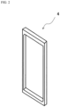
- FIG. 2 shows a perspective view of main parts of the chamber frame element 4 that constitute an intermediate chamber for such a three-chamber electrolyzer as shown in FIG. 1 .
- the chamber frame element 4 of FIG. 2 has a frame shape with an opening in the central part.
- the chamber frame element 4 has a thickness that is required for attachment of piping used for connecting the chamber frame element 4 with a manifold. It is noted here that the piping to be attached and the manifold are omitted in FIG. 2 .
- the chamber frame element 4 is made of a resin, whereby corrosion caused by a leakage current, which is problematic for conventional metal-made chamber frame elements, can be inhibited.
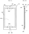
- FIGS. 3A and 3B a chamber frame element 14 according to one embodiment of the present invention, with which the thickness of an intermediate chamber can be reduced, is shown in FIGS. 3A and 3B as a plane view ( FIG. 3A ) and a side view ( FIG. 3B ).
- the chamber frame element 14 of FIGS. 3A and 3B includes: a bag body 141 having an interior space; a frame 142 housed in the bag body 141; and an inlet 143 and an outlet 144 formed on the bag body 141.
- the bag body 141 is made of, for example, resin films, and has a substantially rectangular planar shape in the illustrated example.
- the bag body 141 is formed by superimposing two resin films and sealing the circumference of these films in a bag shape with an adhesive or a heat seal.
- a single resin film may be folded and overlaid, and the circumference of this film except the folded part may be sealed to form a bag.
- the resin film any resin film that is not corroded by an electrolyte solution can be selected and, for example, a film of a polyethylene, a polyester (e.g., PET), a polypropylene, or a common plastic such as PTFE, PFA, or PVC, can be used.
- an opening 141a for allowing ion exchange membranes to face each other as diaphragms is formed.
- the inlet 143 is formed in the vicinity of one longitudinal end of the bag body 141, and the outlet 144 is formed in the vicinity of the other end.
- the bag body 141 has a protruding part 141b and a protruding part 141c, which have a substantially triangular planar shape, on the respective longitudinal ends, and thus has a hexagonal planar shape rather than a substantially rectangular planar shape as a whole.
- the inlet 143 is formed on the protruding part 141b, while the outlet 144 is formed on the protruding part 141c.
- an electrolyte solution introduced into the bag body 141 via the inlet 143 flows in such a manner to spread in the width direction toward the base of the triangular protruding part 141b at one longitudinal end of the bag body 141, so that good fluidity is attained and the electrolyte solution can smoothly flow in the frame 142.
- the electrolyte solution directed from the frame 142 toward the outlet 144 in the bag body 141 flows from the base of the triangular protruding part 141c to the outlet 144 in a converging manner, so that good fluidity is attained and the electrolyte solution can smoothly flow to the outlet 144.
- the protruding parts 141b and 141c of the bag body 141 are not indispensable, and the shape of each longitudinal end of the bag body 141 is not restricted as long as an electrolyte solution can smoothly flow in the bag body 141. Embodiments without the protruding parts 141b and 141c will be described later.
- the inlet 143 has a structure through which an electrolyte solution can be introduced into the bag body 14.
- the outlet 144 has a structure through which the electrolyte solution in the bag body 141 can be discharged.
- the inlet 143 and the outlet 144 are formed by making holes on a single resin film.
- a nozzle 145 is attached to each of the inlet 143 and the outlet 144, and resin-made piping is connected to the nozzle 145.
- the inlet 143 and the outlet 144 are each arranged singly; however, the inlet 143 or the outlet 144 may be arranged in a plural number.
- the electrolyte solution introduced via the inlet 143 into the bag body 141 flows toward the opening 141a.
- the electrolyte solution is ion-exchanged in the opening 141a by the anion exchange membrane 7 and the cation exchange membrane 8, and the thus ion-exchanged electrolyte solution flows toward the outlet 144.
- the chamber frame element 14 is required to have an electrolyte solution flow path formed in the bag body 141.
- the frame 142 is arranged in the interior space of the bag body 141.
- the frame 142 is made of a resin.
- any resin that is not corroded by an electrolyte solution can be selected and, for example, a polyethylene, a polyester (e.g., PET), a polypropylene, a polyvinyl chloride, a polystyrene, a polyurethane, or a common plastic such as PTFE, PFA, or PVC, can be used.
- the planar shape and the size of the opening of the frame 142 are substantially the same as those of the opening 141a of the bag body 141.
- the opening of the frame 142 and the opening 141a of the bag body 141 are aligned at the same position and adhered with each other using an adhesive or the like.
- the frame 142 is provided with a groove or a channel communicating from the outside to the inside of the frame, allowing an electrolyte solution to flow from the inside to the outside of the frame 142 and vice versa.
- grooves 142a communicating to both the outside and the inside of the frame 142 are formed on the surface of the frame 142.
- the grooves 142a are formed on each of a total of two sides among the four sides of the frame 142, which are the side facing the inlet 143 and the side facing the outlet 144.
- the positions, the size, and the number of the grooves are not limited to the ones shown in FIGS. 3A and 3B .
- the thickness of the frame 142 may be as small as possible as long as a sufficient flow rate of an electrolyte solution can be ensured. Accordingly, the thickness of the frame 142 can be reduced to a required minimum as much as possible.
- the amount of voltage drop during electrolysis is determined by a total thickness of the frame 142 and the resin film of the bag body 141; therefore, in the chamber frame element 14 of the present embodiment, a voltage drop can be inhibited by the frame 142 whose thickness is reduced to a required minimum as much as possible.
- an electrolyte solution is introduced and discharged via the piping connected to the inlet 143 and the outlet 144, respectively; therefore, even in an electrolyzer having a structure in which plural unit cells are arranged, the piping connected to the respective unit cells may be assembled together, so that it is not necessary to arrange a manifold inside the chamber frame element 14. Accordingly, a flow path penetrating through all elements is not required as in the case of an intermediate chamber in which a manifold is arranged, and this not only simplifies the unit cell structure and makes the production cost inexpensive, but also enables to reduce the bypass current and thus reduce the consumption of reactive power.
- the chamber frame element 14 has a simple basic structure constituted by two members, which are the bag body 141 and the frame 142, and can be easily produced by pasting together these members by press molding; therefore, the chamber frame element 14 can be easily mass-produced, and the production cost can also be reduced in this respect.
- the size of the chamber frame element 14 can be easily increased as well.
- the bag body 141 and the frame 142 are made of a resin, corrosion caused by a leakage current, which is problematic for conventional metal-made chamber frame elements, can be inhibited.
- FIGS. 4A and 4B show illustrative drawings of a chamber frame element 24 according to another embodiment.
- the chamber frame element 24 of FIGS. 4A and 4B includes: a bag body 241 having an interior space; a frame 242 housed in the bag body 241; and an inlet 243 and an outlet 244 formed on the bag body 241.
- a nozzle 245 is attached to each of the inlet 243 and the outlet 244.
- An opening 241a is formed on the bag body 241, and grooves 242a are formed on the frame 242.
- the chamber frame element 24 shown in FIGS. 4A and 4B is made of a resin, and has a basic structure similar to that of the chamber frame element 14 shown in FIGS. 3A and 3B .
- a difference is that the bag body 241 has a rectangular planar shape. That is, while the bag body 141 of the chamber frame element 14 shown in FIGS. 3A and 3B has the protruding parts 141b and 141c, the bag body 241 of the chamber frame element 24 of this embodiment shown in FIGS. 4A and 4B does not have a protruding part.
- the frame 242, the inlet 243, and the outlet 244 of the chamber frame element 24 shown in FIGS. 4A and 4B have the same configurations as the frame 142, the inlet 143, and the outlet 144 of the chamber frame element 14 shown in FIGS. 3A and 3B , respectively; therefore, descriptions redundant to the above are omitted.
- the chamber frame element 24 has a simple basic structure constituted by two members, which are the bag body 241 and the frame 242, and can be easily produced by pasting together these members by press molding; therefore, the chamber frame element 24 can be easily mass-produced, and the production cost can also be reduced in this respect.
- the size of the chamber frame element 24 can be easily increased as well.
- the bag body 241 and the frame 242 are made of a resin, corrosion caused by a leakage current, which is problematic for conventional metal-made chamber frame elements, can be inhibited.
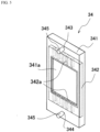
- FIG. 5 shows a perspective view of a chamber frame element 34 according to yet another embodiment.
- the chamber frame element 34 of FIG. 5 includes: a bag body 341 having an interior space; a frame 342 housed in the bag body 341; and an inlet 343 and an outlet 344 formed on the bag body 341.
- a nozzle 345 is attached to each of the inlet 343 and the outlet 344.
- An opening 341a is formed on the bag body 341, and grooves 342a are formed on the frame 342.
- the chamber frame element 34 shown in FIG. 5 is made of a resin, and has a basic structure similar to that of the chamber frame element 14 shown in FIGS. 3A and 3B .
- a difference is that the bag body 341 has a substantially cuboid box shape.
- the frame 342, the inlet 343, and the outlet 344 of the chamber frame element 34 shown in FIG. 5 have the same configurations as the frame 142, the inlet 143, and the outlet 144 of the chamber frame element 14 shown in FIGS. 3A and 3B , respectively; therefore, descriptions redundant to the above are omitted.
- the chamber frame element 34 is made of a resin, and has the same actions and effects as the chamber frame element 14 shown in FIGS. 3A and 3B . That is, in the chamber frame element 34, a voltage drop can be inhibited by the frame 342 whose thickness is reduced to a required minimum, and an electrolyte solution is introduced and discharged via the piping connected to the inlet 343 and the outlet 344, respectively; therefore, as opposed to an intermediate chamber in which a manifold is arranged, a flow path penetrating through all elements is not required, and this not only simplifies the unit cell structure and makes the production cost inexpensive, but also enables to reduce the bypass current and thus reduce the consumption of reactive power.
- the chamber frame element 34 has a simple basic structure constituted by two members, which are the bag body 341 and the frame 342, and can be easily produced by pasting together these members by press molding; therefore, the chamber frame element 34 can be easily mass-produced, and the production cost can also be reduced in this respect.
- the size of the chamber frame element 34 can be easily increased as well.
- the bag body 341 and the frame 342 are made of a resin, corrosion caused by a leakage current, which is problematic for conventional metal-made chamber frame elements, can be inhibited.
- the bag body can take various shapes.
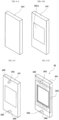
- FIGS. 6A to 6D One example of a method of producing a chamber frame element will now be described for the case of the chamber frame element 34 shown in FIG. 5 , referring to FIGS. 6A to 6D .
- the bag body 341 is produced from a resin film.
- any known method and apparatus can be employed.
- At least one surface of the bag body 341 is made openable such that the frame 342 can be later inserted into the interior space of the bag body 341.
- the opening 341a for application of an electric current is formed on both of the opposing surfaces of the bag body 341.
- the inlet 343 and the outlet 344 are formed on the bag body 341, and the nozzle 345 is attached to each of the inlet 343 and the outlet 344.
- the formation of the opening 341a shown in FIG. 6B and the formation of the inlet 343 and the outlet 344 may be carried out in any order, and the formation of the inlet 343 and the outlet 344 may be carried out before the formation of the opening 341a.
- the frame 342 is inserted into and adhered with the bag body 341, and the outer periphery of the bag body 341 is sealed with an adhesive or a heat seal.
Landscapes
- Chemical & Material Sciences (AREA)
- Engineering & Computer Science (AREA)
- Chemical Kinetics & Catalysis (AREA)
- Electrochemistry (AREA)
- Organic Chemistry (AREA)
- Materials Engineering (AREA)
- Metallurgy (AREA)
- Water Supply & Treatment (AREA)
- Health & Medical Sciences (AREA)
- Urology & Nephrology (AREA)
- Life Sciences & Earth Sciences (AREA)
- General Chemical & Material Sciences (AREA)
- Hydrology & Water Resources (AREA)
- Environmental & Geological Engineering (AREA)
- Inorganic Chemistry (AREA)
- Analytical Chemistry (AREA)
- Molecular Biology (AREA)
- Electrolytic Production Of Non-Metals, Compounds, Apparatuses Therefor (AREA)
- Separation Using Semi-Permeable Membranes (AREA)
- Water Treatment By Electricity Or Magnetism (AREA)
Description
- The present invention relates to: a chamber frame element for an electrolyzer; and an electrolyzer and an electrodialysis cell, which include the chamber frame element.
- Three-chamber electrolysis and the like are used in salt separation processes, lithium hydroxide production processes, organic electrolysis processes, hypochlorous acid production processes and the like. A three-chamber electrolyzer has, as a basic structure, a unit cell including an anode chamber, an intermediate chamber and a cathode chamber, in which an anode is housed in the anode chamber, a cathode is housed in the cathode chamber, the anode chamber and the intermediate chamber are separated by an anion exchange membrane in an anion-permeable manner, and the cathode chamber and the intermediate chamber are separated by a cation exchange membrane in a cation-permeable manner (Patent Document 1).
- A conventional intermediate chamber of such a three-chamber electrolyzer is an element which generally includes a metal-made frame, and in which a liquid inlet and a liquid outlet are arranged on this frame and an electrolyte solution can be circulated inside the frame through the inlet and the outlet.
- In addition to the three-chamber electrolyzers, there are two-chamber electrolyzers that include an anode chamber in which an anode is arranged, a cathode chamber in which a cathode is arranged, and an ion exchange membrane arranged as a diaphragm between the anode chamber and the cathode chamber. As one of such two-chamber electrolyzers, a two-chamber electrolyzer in which unit cells, each of which is constituted by: a bipolar electrode having an anode arranged on one side of a membrane and a cathode arranged on the other side of the membrane; an anode chamber arranged on the anode side of the bipolar electrode; and a cathode chamber arranged on the cathode side of the bipolar electrode, are sequentially disposed with an ion exchange membrane being arranged as a diaphragm between each anode chamber and cathode chamber is used in some cases. Alternatively, depending on the electrolysis process, a single-chamber electrolyzer having no diaphragm (diaphragm-free single-chamber electrolyzer), in which an electrolysis chamber is arranged on the anode side of the above-described bipolar electrode and another electrolysis chamber is arranged on the cathode side of the bipolar electrode, may be used. A metal-made frame is also used in the electrolysis chambers (the general term "electrolysis chamber" used herein encompasses an anode chamber, a cathode chamber, and an intermediate chamber) of these single-chamber and two-chamber electrolyzers.
- Further, there are some electrolysis chambers that include an element constituted by a frame made of a resin rather than a metal.
- Moreover, a metal-made frame is also used in electrodialysis cells that perform electrodialysis.
-
Patent Document 2 discloses an electrode chamber having an anode and a cation exchange membrane installed on a frame, characterised in that the exchange membrane is open at the top and has a bag-like structure whose shape and size are matched with the frame and the outside of the frame is sheathed with the exchange membrane. -
- [Patent Document 1]
JP2015-182008A - [Patent Document 2]
CN87208091U - In an electrolysis chamber of a conventional electrolyzer, for example, for connecting a manifold to the inlet and the outlet that are arranged on the frame, the frame is required to have a certain thickness, i.e. a certain dimension in the respective directions toward the electrodes of the anode chamber and the cathode chamber in the case of an intermediate chamber of a three-chamber electrolyzer. During an electrolysis treatment, the frame thickness of this electrolysis chamber causes a drop in the voltage that is applied between the anode of the anode chamber adjacent to the electrolysis chamber and the cathode of the cathode chamber adjacent to the electrolysis chamber. The amount of this voltage drop directly relates to the power consumption during electrolysis. Further, since the voltage drop induces heating of an electrolyte solution in the electrolysis chamber, a greater amount of voltage drop leads to an increase in the consumption of energy for cooling. Accordingly, it is desired to inhibit such a voltage drop as much as possible; however, the inhibition of a voltage drop is limited due to the above-described frame thickness.
- Further, since the frame of an electrolysis chamber of a conventional electrolyzer is made of a metal, a leakage current occurs between the frame and a ground during electrolysis, and this causes corrosion of the metal. Accordingly, as a countermeasure against the metal corrosion, a sacrificial electrode is arranged in the electrolyzer in such a manner that it is electrically connected to the frame of the electrolysis chamber or a metal casing welded to the frame. However, despite that the sacrificial electrode needs to be replaced regularly, the sacrificial electrode is welded to an equipment of the electrolyzer and thus not easily replaceable, which requires a work cost for the replacement and a material cost of the sacrificial electrode itself.
- In the case of an electrolysis chamber constituted by a resin element, metal corrosion of the electrolysis chamber caused by a leakage current is not an issue; however, an electrolyte solution is circulated between the electrolysis chamber and the outside through a manifold arranged inside the electrolysis chamber. Accordingly, for the formation of the manifold, a flow path that penetrates all elements is required in an electrolyzer in which plural unit cells are arranged. In addition, in an element having a structure in which a manifold is arranged inside an electrolysis chamber, the distance with its adjacent element is generally close; therefore, the consumption of reactive power increases due to a larger bypass current.
- The present invention was made in view of the above-described problems, and an object of the present invention is to provide: a chamber frame element having a smaller amount of voltage drop and less consumption of reactive power than the prior art; and an electrolyzer and an electrodialysis cell including the chamber frame element.
- A first aspect of the present invention is a chamber frame element for an electrolyzer or an electrodialysis cell according to
claim 1. - In the first aspect of the present invention, it is preferred that the chamber frame element be made of a resin.
- Further, in the first aspect of the present invention, the chamber frame element is preferably a chamber frame element for a three-chamber electrolyzer.
- A second aspect of the present invention is an electrolyzer including the chamber frame element of the first aspect.
- A third aspect of the present invention is an electrodialysis cell including the chamber frame element of the first aspect.
- According to the present invention, an intermediate chamber can be reduced in thickness, and the amount of voltage drop during electrolysis can be reduced. In addition, since a manifold is not arranged inside an electrolysis chamber, a bypass current is small, and the consumption of reactive power is limited.
-
- [
FIG. 1] FIG. 1 is a schematic cross-sectional view of an electrolyzer. - [
FIG. 2] FIG. 2 is a schematic perspective view of a chamber frame element. - [
FIG. 3A] FIG. 3A is an illustrative drawing of a front view of a chamber frame element according to the present embodiment. - [
FIG. 3B] FIG. 3B is an illustrative drawing of a side view of a chamber frame element according to the present embodiment. - [
FIG. 4A] FIG. 4A is an illustrative drawing of a front view of a chamber frame element according to another embodiment. - [
FIG. 4B] FIG. 4B is an illustrative drawing of a side view of a chamber frame element according to another embodiment. - [
FIG. 5] FIG. 5 is a perspective view of a chamber frame element according to yet another embodiment. - [
FIG. 6A] FIG. 6A is a perspective view illustrating one example of a production process of a chamber frame element. - [
FIG. 6B] FIG. 6B is a perspective view illustrating one example of a production process of a chamber frame element. - [
FIG. 6C] FIG. 6C is a perspective view illustrating one example of a production process of a chamber frame element. - [
FIG. 6D] FIG. 6D is a perspective view illustrating one example of a production process of a chamber frame element. - Embodiments of the chamber frame element, the electrolyzer, and the electrodialysis cell according to the present invention will now be described referring to the drawings. In the following descriptions, a chamber frame element used for an intermediate chamber of a three-chamber electrolyzer is described as a representative example of the chamber frame element of the present invention, and a three-chamber electrolyzer is described as a representative example of the electrolyzer of the present invention; however, the chamber frame element of the present invention is not limited to be used for an intermediate chamber of a three-chamber electrolyzer, and can be used in the same manner also for an anode chamber and a cathode chamber of a two-chamber electrolyzer, as well as an electrolysis chamber of a single-chamber electrolyzer. Further, the electrolyzer of the present invention is not limited to be a three-chamber electrolyzer, and can be a two-chamber or single-chamber electrolyzer in which the chamber frame element of the present invention is used. Moreover, the chamber frame element of the present invention is not limited to be used in an electrolyzer, and can be used in an electrodialysis cell.
-
FIG. 1 is a schematic cross-sectional view of a three-chamber electrolyzer 1 in which a chamber frame element according to one embodiment of the present invention is used. InFIG. 1 , the three-chamber electrolyzer 1 includes: ananode chamber 3 in which ananode 2 is housed; anintermediate chamber 4; and acathode chamber 6 in which acathode 5 is housed. Theanode chamber 3 and theintermediate chamber 4 are separated by ananion exchange membrane 7 in an anion-permeable manner. Theintermediate chamber 4 and thecathode chamber 5 are separated by acation exchange membrane 8 in a cation-permeable manner. - Describing one example of electrolysis using the three-
chamber electrolyzer 1 for the case of sodium sulfate, when an aqueous sodium sulfate solution as an electrolyte solution is introduced to theintermediate chamber 4 and electric power is supplied between theanode 2 and thecathode 5 to perform electrolysis, sulfate ions pass through theanion exchange membrane 7 and move to theanode chamber 3, while sodium ions pass through thecation exchange membrane 8 and move to thecathode chamber 6. The thus diluted aqueous solution is discharged from theintermediate chamber 4. -
FIG. 2 shows a perspective view of main parts of thechamber frame element 4 that constitute an intermediate chamber for such a three-chamber electrolyzer as shown inFIG. 1 . Thechamber frame element 4 ofFIG. 2 has a frame shape with an opening in the central part. As for the thickness of thechamber frame element 4, thechamber frame element 4 has a thickness that is required for attachment of piping used for connecting thechamber frame element 4 with a manifold. It is noted here that the piping to be attached and the manifold are omitted inFIG. 2 . Thechamber frame element 4 is made of a resin, whereby corrosion caused by a leakage current, which is problematic for conventional metal-made chamber frame elements, can be inhibited. - Nevertheless, with the
chamber frame element 4 in which the material of a conventional metal-made chamber frame element is simply changed to a resin without changing the shape, the thickness of an intermediate chamber stays the same, and a voltage drop during electrolysis is thus not inhibited relative to the prior art. In this respect, achamber frame element 14 according to one embodiment of the present invention, with which the thickness of an intermediate chamber can be reduced, is shown inFIGS. 3A and 3B as a plane view (FIG. 3A ) and a side view (FIG. 3B ). - The
chamber frame element 14 ofFIGS. 3A and 3B includes: abag body 141 having an interior space; aframe 142 housed in thebag body 141; and aninlet 143 and anoutlet 144 formed on thebag body 141. - The
bag body 141 is made of, for example, resin films, and has a substantially rectangular planar shape in the illustrated example. Thebag body 141 is formed by superimposing two resin films and sealing the circumference of these films in a bag shape with an adhesive or a heat seal. Instead of preparing two resin films, a single resin film may be folded and overlaid, and the circumference of this film except the folded part may be sealed to form a bag. As the resin film, any resin film that is not corroded by an electrolyte solution can be selected and, for example, a film of a polyethylene, a polyester (e.g., PET), a polypropylene, or a common plastic such as PTFE, PFA, or PVC, can be used. - In the central part of each of the two resin films constituting the
bag body 141, anopening 141a for allowing ion exchange membranes to face each other as diaphragms is formed. In the illustrated present embodiment, on the outer side of the portion of thebag body 141 in which the above-described frame is housed, theinlet 143 is formed in the vicinity of one longitudinal end of thebag body 141, and theoutlet 144 is formed in the vicinity of the other end. - More specifically, in the present embodiment shown in
FIGS. 3A and 3B , thebag body 141 has aprotruding part 141b and aprotruding part 141c, which have a substantially triangular planar shape, on the respective longitudinal ends, and thus has a hexagonal planar shape rather than a substantially rectangular planar shape as a whole. Theinlet 143 is formed on theprotruding part 141b, while theoutlet 144 is formed on theprotruding part 141c. As a result, an electrolyte solution introduced into thebag body 141 via theinlet 143 flows in such a manner to spread in the width direction toward the base of the triangular protrudingpart 141b at one longitudinal end of thebag body 141, so that good fluidity is attained and the electrolyte solution can smoothly flow in theframe 142. In addition, the electrolyte solution directed from theframe 142 toward theoutlet 144 in thebag body 141 flows from the base of the triangular protrudingpart 141c to theoutlet 144 in a converging manner, so that good fluidity is attained and the electrolyte solution can smoothly flow to theoutlet 144. It is noted here that the protrudingparts bag body 141 are not indispensable, and the shape of each longitudinal end of thebag body 141 is not restricted as long as an electrolyte solution can smoothly flow in thebag body 141. Embodiments without the protrudingparts - The
inlet 143 has a structure through which an electrolyte solution can be introduced into thebag body 14. Theoutlet 144 has a structure through which the electrolyte solution in thebag body 141 can be discharged. In the example shown inFIGS. 3A and 3B , theinlet 143 and theoutlet 144 are formed by making holes on a single resin film. Anozzle 145 is attached to each of theinlet 143 and theoutlet 144, and resin-made piping is connected to thenozzle 145. In the example shown inFIGS. 3A and 3B , theinlet 143 and theoutlet 144 are each arranged singly; however, theinlet 143 or theoutlet 144 may be arranged in a plural number. - The electrolyte solution introduced via the
inlet 143 into thebag body 141 flows toward theopening 141a. In the case of the three-chamber electrolyzer shown inFIG. 1 , the electrolyte solution is ion-exchanged in theopening 141a by theanion exchange membrane 7 and thecation exchange membrane 8, and the thus ion-exchanged electrolyte solution flows toward theoutlet 144. - In order to ensure a flow rate necessary for such a series of electrolysis processes, the
chamber frame element 14 is required to have an electrolyte solution flow path formed in thebag body 141. Accordingly, in thechamber frame element 14 of the present embodiment, theframe 142 is arranged in the interior space of thebag body 141. Theframe 142 is made of a resin. As the resin of theframe 142, any resin that is not corroded by an electrolyte solution can be selected and, for example, a polyethylene, a polyester (e.g., PET), a polypropylene, a polyvinyl chloride, a polystyrene, a polyurethane, or a common plastic such as PTFE, PFA, or PVC, can be used. - The planar shape and the size of the opening of the
frame 142 are substantially the same as those of theopening 141a of thebag body 141. The opening of theframe 142 and theopening 141a of thebag body 141 are aligned at the same position and adhered with each other using an adhesive or the like. Theframe 142 is provided with a groove or a channel communicating from the outside to the inside of the frame, allowing an electrolyte solution to flow from the inside to the outside of theframe 142 and vice versa. In the chamber frame element of the present embodiment that is shown inFIGS. 3A and 3B ,grooves 142a communicating to both the outside and the inside of theframe 142 are formed on the surface of theframe 142. In the illustrated present embodiment, thegrooves 142a are formed on each of a total of two sides among the four sides of theframe 142, which are the side facing theinlet 143 and the side facing theoutlet 144. The positions, the size, and the number of the grooves are not limited to the ones shown inFIGS. 3A and 3B . - In the
chamber frame element 14 of the present embodiment, the thickness of theframe 142 may be as small as possible as long as a sufficient flow rate of an electrolyte solution can be ensured. Accordingly, the thickness of theframe 142 can be reduced to a required minimum as much as possible. The amount of voltage drop during electrolysis is determined by a total thickness of theframe 142 and the resin film of thebag body 141; therefore, in thechamber frame element 14 of the present embodiment, a voltage drop can be inhibited by theframe 142 whose thickness is reduced to a required minimum as much as possible. - Further, in the
chamber frame element 14, an electrolyte solution is introduced and discharged via the piping connected to theinlet 143 and theoutlet 144, respectively; therefore, even in an electrolyzer having a structure in which plural unit cells are arranged, the piping connected to the respective unit cells may be assembled together, so that it is not necessary to arrange a manifold inside thechamber frame element 14. Accordingly, a flow path penetrating through all elements is not required as in the case of an intermediate chamber in which a manifold is arranged, and this not only simplifies the unit cell structure and makes the production cost inexpensive, but also enables to reduce the bypass current and thus reduce the consumption of reactive power. - Moreover, the
chamber frame element 14 has a simple basic structure constituted by two members, which are thebag body 141 and theframe 142, and can be easily produced by pasting together these members by press molding; therefore, thechamber frame element 14 can be easily mass-produced, and the production cost can also be reduced in this respect. The size of thechamber frame element 14 can be easily increased as well. Furthermore, in thechamber frame element 14, since thebag body 141 and theframe 142 are made of a resin, corrosion caused by a leakage current, which is problematic for conventional metal-made chamber frame elements, can be inhibited. -
FIGS. 4A and 4B show illustrative drawings of achamber frame element 24 according to another embodiment. Thechamber frame element 24 ofFIGS. 4A and 4B includes: abag body 241 having an interior space; aframe 242 housed in thebag body 241; and aninlet 243 and anoutlet 244 formed on thebag body 241. Anozzle 245 is attached to each of theinlet 243 and theoutlet 244. Anopening 241a is formed on thebag body 241, andgrooves 242a are formed on theframe 242. - The
chamber frame element 24 shown inFIGS. 4A and 4B is made of a resin, and has a basic structure similar to that of thechamber frame element 14 shown inFIGS. 3A and 3B . A difference is that thebag body 241 has a rectangular planar shape. That is, while thebag body 141 of thechamber frame element 14 shown inFIGS. 3A and 3B has the protrudingparts bag body 241 of thechamber frame element 24 of this embodiment shown inFIGS. 4A and 4B does not have a protruding part. Theframe 242, theinlet 243, and theoutlet 244 of thechamber frame element 24 shown inFIGS. 4A and 4B have the same configurations as theframe 142, theinlet 143, and theoutlet 144 of thechamber frame element 14 shown inFIGS. 3A and 3B , respectively; therefore, descriptions redundant to the above are omitted. - The
chamber frame element 24 shown inFIGS. 4A and 4B has the same effects as thechamber frame element 14 shown inFIGS. 3A and 3B . That is, in thechamber frame element 24, a voltage drop can be inhibited by theframe 242 whose thickness is reduced to a required minimum, and an electrolyte solution is introduced and discharged via the piping connected to theinlet 243 and theoutlet 244, respectively; therefore, as opposed to an intermediate chamber in which a manifold is arranged, a flow path penetrating through all elements is not required, and this not only simplifies the unit cell structure and makes the production cost inexpensive, but also enables to reduce the bypass current and thus reduce the consumption of reactive power. Further, thechamber frame element 24 has a simple basic structure constituted by two members, which are thebag body 241 and theframe 242, and can be easily produced by pasting together these members by press molding; therefore, thechamber frame element 24 can be easily mass-produced, and the production cost can also be reduced in this respect. The size of thechamber frame element 24 can be easily increased as well. Moreover, in thechamber frame element 24, since thebag body 241 and theframe 242 are made of a resin, corrosion caused by a leakage current, which is problematic for conventional metal-made chamber frame elements, can be inhibited. -
FIG. 5 shows a perspective view of achamber frame element 34 according to yet another embodiment. Thechamber frame element 34 ofFIG. 5 includes: abag body 341 having an interior space; aframe 342 housed in thebag body 341; and aninlet 343 and anoutlet 344 formed on thebag body 341. Anozzle 345 is attached to each of theinlet 343 and theoutlet 344. Anopening 341a is formed on thebag body 341, andgrooves 342a are formed on theframe 342. - The
chamber frame element 34 shown inFIG. 5 is made of a resin, and has a basic structure similar to that of thechamber frame element 14 shown inFIGS. 3A and 3B . A difference is that thebag body 341 has a substantially cuboid box shape. Theframe 342, theinlet 343, and theoutlet 344 of thechamber frame element 34 shown inFIG. 5 have the same configurations as theframe 142, theinlet 143, and theoutlet 144 of thechamber frame element 14 shown inFIGS. 3A and 3B , respectively; therefore, descriptions redundant to the above are omitted. - The
chamber frame element 34 is made of a resin, and has the same actions and effects as thechamber frame element 14 shown inFIGS. 3A and 3B . That is, in thechamber frame element 34, a voltage drop can be inhibited by theframe 342 whose thickness is reduced to a required minimum, and an electrolyte solution is introduced and discharged via the piping connected to theinlet 343 and theoutlet 344, respectively; therefore, as opposed to an intermediate chamber in which a manifold is arranged, a flow path penetrating through all elements is not required, and this not only simplifies the unit cell structure and makes the production cost inexpensive, but also enables to reduce the bypass current and thus reduce the consumption of reactive power. Further, thechamber frame element 34 has a simple basic structure constituted by two members, which are thebag body 341 and theframe 342, and can be easily produced by pasting together these members by press molding; therefore, thechamber frame element 34 can be easily mass-produced, and the production cost can also be reduced in this respect. The size of thechamber frame element 34 can be easily increased as well. Moreover, in thechamber frame element 34, since thebag body 341 and theframe 342 are made of a resin, corrosion caused by a leakage current, which is problematic for conventional metal-made chamber frame elements, can be inhibited. - As understood from
FIGS. 3 to 5 , the bag body can take various shapes. - One example of a method of producing a chamber frame element will now be described for the case of the
chamber frame element 34 shown inFIG. 5 , referring toFIGS. 6A to 6D . - As shown in
FIG. 6A , thebag body 341 is produced from a resin film. As a method and an apparatus for the production of thebag body 341, any known method and apparatus can be employed. At least one surface of thebag body 341 is made openable such that theframe 342 can be later inserted into the interior space of thebag body 341. - Next, as shown in
FIG. 6B , theopening 341a for application of an electric current is formed on both of the opposing surfaces of thebag body 341. - Subsequently, as shown in
FIG. 6C , theinlet 343 and theoutlet 344 are formed on thebag body 341, and thenozzle 345 is attached to each of theinlet 343 and theoutlet 344. - It is noted here that the formation of the
opening 341a shown inFIG. 6B and the formation of theinlet 343 and theoutlet 344 may be carried out in any order, and the formation of theinlet 343 and theoutlet 344 may be carried out before the formation of theopening 341a. - Thereafter, as shown in
FIG. 6D , theframe 342 is inserted into and adhered with thebag body 341, and the outer periphery of thebag body 341 is sealed with an adhesive or a heat seal. -
- 1: three-chamber electrolyzer
- 2: anode
- 3: anode chamber
- 4: intermediate chamber (chamber frame element)
- 5: cathode
- 6: cathode chamber
- 7: anion exchange membrane
- 8: cation exchange membrane
- 14, 24, 34: chamber frame element
- 141, 241, 341: bag body
- 142, 242, 342: frame
- 143, 243, 343: inlet
- 144, 244, 344: outlet
- 145, 245, 345: nozzle
Claims (5)
- A chamber frame element (4, 14, 24, 34) for an electrolyzer or an electrodialysis cell, the chamber frame element (4, 14, 24, 34) comprising:a bag body (141, 241, 341);a frame (142, 242, 342) housed in an interior space of the bag body (141, 241, 341); and an inlet (143, 243, 343) and an outlet (144, 244, 344) to which piping can be attached, the inlet (143, 243, 343) and the outlet (144, 244, 344) being formed on the outside of a region where the frame (142, 242, 342) is housed in the bag body (141, 241, 341), wherein the frame (142, 242, 342) comprises a flow path that allows a liquid inflowing from the inlet (143, 243, 343) to flow inside the frame (142, 242, 342) and a liquid inside the frame (142, 242, 342) to flow to the outlet (144, 244, 344), and the flow path is a groove (142a, 242a, 342a) or a channel that communicates to the outside and the inside of the frame (142, 242, 342).
- The chamber frame element (4, 14, 24, 34) according to claim 1, wherein the chamber frame element (4, 14, 24, 34) is made of a resin.
- The chamber frame element (4, 14, 24, 34) according to claim 1, wherein the chamber frame element (4, 14, 24, 34) is for a three-chamber electrolyzer (1).
- An electrolyzer comprising the chamber frame element (4, 14, 24, 34) according to any one of claims 1 to 3.
- An electrodialysis cell comprising the chamber frame element (4, 14, 24, 34) according to any one of claims 1 to 3.
Applications Claiming Priority (2)
| Application Number | Priority Date | Filing Date | Title |
|---|---|---|---|
| JP2019008075A JP6778286B2 (en) | 2019-01-21 | 2019-01-21 | Chamber frame element, electrolytic cell and electrodialysis tank |
| PCT/JP2020/001595 WO2020153273A1 (en) | 2019-01-21 | 2020-01-17 | Chamber frame element, electrolytic cell, and electrodialysis cell |
Publications (4)
| Publication Number | Publication Date |
|---|---|
| EP3916130A1 EP3916130A1 (en) | 2021-12-01 |
| EP3916130A4 EP3916130A4 (en) | 2022-12-07 |
| EP3916130B1 true EP3916130B1 (en) | 2025-03-12 |
| EP3916130C0 EP3916130C0 (en) | 2025-03-12 |
Family
ID=71736085
Family Applications (1)
| Application Number | Title | Priority Date | Filing Date |
|---|---|---|---|
| EP20745620.3A Active EP3916130B1 (en) | 2019-01-21 | 2020-01-17 | Chamber frame element, electrolyzer, and electrodialysis cell |
Country Status (10)
| Country | Link |
|---|---|
| US (1) | US11365484B2 (en) |
| EP (1) | EP3916130B1 (en) |
| JP (1) | JP6778286B2 (en) |
| KR (1) | KR102408265B1 (en) |
| CN (1) | CN113272476B (en) |
| BR (1) | BR112021013967B1 (en) |
| CA (1) | CA3125094C (en) |
| ES (1) | ES3015531T3 (en) |
| TW (1) | TWI822944B (en) |
| WO (1) | WO2020153273A1 (en) |
Families Citing this family (1)
| Publication number | Priority date | Publication date | Assignee | Title |
|---|---|---|---|---|
| CN113755859A (en) * | 2021-10-18 | 2021-12-07 | 厦门仲鑫达氢能技术有限公司 | Electrolytic cell with multi-channel frame structure inside |
Family Cites Families (18)
| Publication number | Priority date | Publication date | Assignee | Title |
|---|---|---|---|---|
| JPS5891179A (en) * | 1981-11-24 | 1983-05-31 | Chlorine Eng Corp Ltd | Electrolytic cell by ion exchange membrane method |
| GB8626629D0 (en) * | 1986-11-07 | 1986-12-10 | Ici Plc | Electrolytic cell |
| CN87208091U (en) * | 1987-05-14 | 1987-12-30 | 鲁仁成 | Electrode chamber with baggy ion exchange membrane |
| EP0814884A4 (en) * | 1995-03-23 | 2000-01-05 | Ionics | Improvements in membrane processes including electrodialysis |
| US6391170B1 (en) * | 2000-12-01 | 2002-05-21 | Envirotech Pumpsystems, Inc. | Anode box for electrometallurgical processes |
| CN101327668A (en) * | 2002-11-22 | 2008-12-24 | 东洋制罐株式会社 | Method for manufacturing package bag with self-closing nozzle |
| US7459065B2 (en) * | 2004-02-18 | 2008-12-02 | General Motors Corporation | Hydrogen generator photovoltaic electrolysis reactor system |
| DE102005015307A1 (en) | 2005-04-01 | 2006-10-05 | Heraeus Kulzer Gmbh | Container, in particular for galvanic baths |
| KR100790680B1 (en) | 2007-01-16 | 2008-01-02 | 삼성전기주식회사 | Hydrogen Generator |
| CN102121113B (en) * | 2011-01-28 | 2014-09-03 | 广州赛爱环境保护技术开发有限公司 | Three-slot combined electrolyzer |
| EP2692903B1 (en) | 2012-08-02 | 2018-02-21 | VARTA Microbattery GmbH | Cellule de développement d'hydrogène avec poche pour cathode |
| WO2014122657A1 (en) * | 2013-02-11 | 2014-08-14 | B.G. Negev Technologies And Applications Ltd. | Apparatus and system for deionization |
| CN103409772B (en) * | 2013-08-13 | 2017-07-21 | 四川省尼科国润新材料有限公司 | A kind of circulating system device of closed frame electro deposited nickel or electrodeposited cobalt electrolyte |
| JP2015182008A (en) | 2014-03-24 | 2015-10-22 | 株式会社東芝 | Electrolyzed water generator |
| EP3126036B1 (en) * | 2014-04-02 | 2022-03-09 | Evoqua Water Technologies LLC | Cross-flow electrochemical separation devices and methods of assembling same |
| JP6709621B2 (en) * | 2015-01-20 | 2020-06-17 | Agcエンジニアリング株式会社 | Electrodialysis machine |
| JP2017056376A (en) * | 2015-09-14 | 2017-03-23 | 株式会社東芝 | ELECTROLYTIC CELL AND ELECTROLYTIC WATER GENERATOR HAVING THE SAME |
| WO2018136337A2 (en) * | 2017-01-18 | 2018-07-26 | Aqua Metals Inc. | Pretreatment of diaphragms used in electrochemical processes |
-
2019
- 2019-01-21 JP JP2019008075A patent/JP6778286B2/en active Active
-
2020
- 2020-01-17 KR KR1020217026060A patent/KR102408265B1/en active Active
- 2020-01-17 CN CN202080008671.6A patent/CN113272476B/en active Active
- 2020-01-17 ES ES20745620T patent/ES3015531T3/en active Active
- 2020-01-17 CA CA3125094A patent/CA3125094C/en active Active
- 2020-01-17 BR BR112021013967-2A patent/BR112021013967B1/en active IP Right Grant
- 2020-01-17 US US17/424,445 patent/US11365484B2/en active Active
- 2020-01-17 EP EP20745620.3A patent/EP3916130B1/en active Active
- 2020-01-17 WO PCT/JP2020/001595 patent/WO2020153273A1/en not_active Ceased
- 2020-01-21 TW TW109102141A patent/TWI822944B/en active
Also Published As
| Publication number | Publication date |
|---|---|
| KR102408265B1 (en) | 2022-06-10 |
| JP6778286B2 (en) | 2020-10-28 |
| EP3916130A4 (en) | 2022-12-07 |
| BR112021013967B1 (en) | 2022-07-12 |
| KR20210106016A (en) | 2021-08-27 |
| TW202041718A (en) | 2020-11-16 |
| CN113272476B (en) | 2022-06-24 |
| ES3015531T3 (en) | 2025-05-06 |
| WO2020153273A8 (en) | 2021-04-29 |
| US20220074058A1 (en) | 2022-03-10 |
| WO2020153273A1 (en) | 2020-07-30 |
| BR112021013967A2 (en) | 2021-09-21 |
| EP3916130A1 (en) | 2021-12-01 |
| EP3916130C0 (en) | 2025-03-12 |
| CA3125094C (en) | 2022-05-10 |
| CN113272476A (en) | 2021-08-17 |
| JP2020117745A (en) | 2020-08-06 |
| CA3125094A1 (en) | 2020-07-30 |
| US11365484B2 (en) | 2022-06-21 |
| TWI822944B (en) | 2023-11-21 |
Similar Documents
| Publication | Publication Date | Title |
|---|---|---|
| CN103298543B (en) | For improving the technology of the current efficiency in Electrochemical separation system and method | |
| CN102618881A (en) | Electrolytic tank | |
| JP2014014776A (en) | Electric dialysis device | |
| CN106044966A (en) | Electrodialysis apparatus | |
| US9163320B2 (en) | Electrolytic cell having a transition duct outlet | |
| CA3125094C (en) | Chamber frame element, electrolyzer, and electrodialysis cell | |
| CN105800743B (en) | Electrodialysis device | |
| JP5980524B2 (en) | Electrolytic chamber, electrolytic cell unit, electrolytic cell stack, and hydrogen generator | |
| US5637204A (en) | End casing for an electrodialyzer electrodialyzer equipped with such a casing and use of the said electrodialyzer | |
| KR20220041227A (en) | electrolyzer | |
| KR101471173B1 (en) | electrolytic cell of a water purifier using an electrolysis | |
| CN207375798U (en) | Electrolytic cell and electrolyzed water generating device having the electrolytic cell | |
| KR20140016223A (en) | Electrolytic cell of a water purifier using an electrolysis | |
| KR101453025B1 (en) | electrolytic cell of a water purifier using an electrolysis | |
| JP2016097355A (en) | Dialyzer | |
| HK1189996A (en) | Flow distributors for electrochemical separation | |
| HK1188263A (en) | Modular electrochemical systems and methods | |
| HK1188338A (en) | Electrochemical separation modules | |
| KR20140016221A (en) | Electrolytic cell of a water purifier using an electrolysis | |
| HK1122073B (en) | Membrane electrolytic reactors system with four chambers | |
| HK1122073A1 (en) | Membrane electrolytic reactors system with four chambers |
Legal Events
| Date | Code | Title | Description |
|---|---|---|---|
| STAA | Information on the status of an ep patent application or granted ep patent |
Free format text: STATUS: THE INTERNATIONAL PUBLICATION HAS BEEN MADE |
|
| PUAI | Public reference made under article 153(3) epc to a published international application that has entered the european phase |
Free format text: ORIGINAL CODE: 0009012 |
|
| STAA | Information on the status of an ep patent application or granted ep patent |
Free format text: STATUS: REQUEST FOR EXAMINATION WAS MADE |
|
| 17P | Request for examination filed |
Effective date: 20210809 |
|
| AK | Designated contracting states |
Kind code of ref document: A1 Designated state(s): AL AT BE BG CH CY CZ DE DK EE ES FI FR GB GR HR HU IE IS IT LI LT LU LV MC MK MT NL NO PL PT RO RS SE SI SK SM TR |
|
| DAV | Request for validation of the european patent (deleted) | ||
| DAX | Request for extension of the european patent (deleted) | ||
| REG | Reference to a national code |
Ref country code: DE Ref legal event code: R079 Ipc: C25B0015080000 Ref country code: DE Ref legal event code: R079 Ref document number: 602020047599 Country of ref document: DE Free format text: PREVIOUS MAIN CLASS: C25B0009080000 Ipc: C25B0015080000 |
|
| A4 | Supplementary search report drawn up and despatched |
Effective date: 20221108 |
|
| RIC1 | Information provided on ipc code assigned before grant |
Ipc: B01D 61/48 20060101ALI20221102BHEP Ipc: C25B 9/60 20210101ALI20221102BHEP Ipc: C25B 9/21 20210101ALI20221102BHEP Ipc: C25B 3/00 20210101ALI20221102BHEP Ipc: C25B 1/26 20060101ALI20221102BHEP Ipc: C25B 1/20 20060101ALI20221102BHEP Ipc: C25B 15/08 20060101AFI20221102BHEP |
|
| STAA | Information on the status of an ep patent application or granted ep patent |
Free format text: STATUS: EXAMINATION IS IN PROGRESS |
|
| 17Q | First examination report despatched |
Effective date: 20230807 |
|
| GRAP | Despatch of communication of intention to grant a patent |
Free format text: ORIGINAL CODE: EPIDOSNIGR1 |
|
| STAA | Information on the status of an ep patent application or granted ep patent |
Free format text: STATUS: GRANT OF PATENT IS INTENDED |
|
| RIC1 | Information provided on ipc code assigned before grant |
Ipc: B01D 61/46 20060101ALI20240918BHEP Ipc: B01D 61/48 20060101ALI20240918BHEP Ipc: C25B 9/60 20210101ALI20240918BHEP Ipc: C25B 9/21 20210101ALI20240918BHEP Ipc: C25B 3/00 20210101ALI20240918BHEP Ipc: C25B 1/26 20060101ALI20240918BHEP Ipc: C25B 1/20 20060101ALI20240918BHEP Ipc: C25B 15/08 20060101AFI20240918BHEP |
|
| INTG | Intention to grant announced |
Effective date: 20241008 |
|
| RIN1 | Information on inventor provided before grant (corrected) |
Inventor name: OKURA, MAKOTO Inventor name: OTSU, HIDEO |
|
| GRAS | Grant fee paid |
Free format text: ORIGINAL CODE: EPIDOSNIGR3 |
|
| GRAA | (expected) grant |
Free format text: ORIGINAL CODE: 0009210 |
|
| STAA | Information on the status of an ep patent application or granted ep patent |
Free format text: STATUS: THE PATENT HAS BEEN GRANTED |
|
| AK | Designated contracting states |
Kind code of ref document: B1 Designated state(s): AL AT BE BG CH CY CZ DE DK EE ES FI FR GB GR HR HU IE IS IT LI LT LU LV MC MK MT NL NO PL PT RO RS SE SI SK SM TR |
|
| REG | Reference to a national code |
Ref country code: GB Ref legal event code: FG4D |
|
| REG | Reference to a national code |
Ref country code: CH Ref legal event code: EP |
|
| REG | Reference to a national code |
Ref country code: DE Ref legal event code: R096 Ref document number: 602020047599 Country of ref document: DE |
|
| REG | Reference to a national code |
Ref country code: IE Ref legal event code: FG4D |
|
| U01 | Request for unitary effect filed |
Effective date: 20250325 |
|
| U07 | Unitary effect registered |
Designated state(s): AT BE BG DE DK EE FI FR IT LT LU LV MT NL PT RO SE SI Effective date: 20250331 |
|
| REG | Reference to a national code |
Ref country code: ES Ref legal event code: FG2A Ref document number: 3015531 Country of ref document: ES Kind code of ref document: T3 Effective date: 20250506 |
|
| PG25 | Lapsed in a contracting state [announced via postgrant information from national office to epo] |
Ref country code: RS Free format text: LAPSE BECAUSE OF FAILURE TO SUBMIT A TRANSLATION OF THE DESCRIPTION OR TO PAY THE FEE WITHIN THE PRESCRIBED TIME-LIMIT Effective date: 20250612 |
|
| PG25 | Lapsed in a contracting state [announced via postgrant information from national office to epo] |
Ref country code: NO Free format text: LAPSE BECAUSE OF FAILURE TO SUBMIT A TRANSLATION OF THE DESCRIPTION OR TO PAY THE FEE WITHIN THE PRESCRIBED TIME-LIMIT Effective date: 20250612 |
|
| PG25 | Lapsed in a contracting state [announced via postgrant information from national office to epo] |
Ref country code: HR Free format text: LAPSE BECAUSE OF FAILURE TO SUBMIT A TRANSLATION OF THE DESCRIPTION OR TO PAY THE FEE WITHIN THE PRESCRIBED TIME-LIMIT Effective date: 20250312 |
|
| PG25 | Lapsed in a contracting state [announced via postgrant information from national office to epo] |
Ref country code: GR Free format text: LAPSE BECAUSE OF FAILURE TO SUBMIT A TRANSLATION OF THE DESCRIPTION OR TO PAY THE FEE WITHIN THE PRESCRIBED TIME-LIMIT Effective date: 20250613 |
|
| PG25 | Lapsed in a contracting state [announced via postgrant information from national office to epo] |
Ref country code: SM Free format text: LAPSE BECAUSE OF FAILURE TO SUBMIT A TRANSLATION OF THE DESCRIPTION OR TO PAY THE FEE WITHIN THE PRESCRIBED TIME-LIMIT Effective date: 20250312 |
|
| PG25 | Lapsed in a contracting state [announced via postgrant information from national office to epo] |
Ref country code: PL Free format text: LAPSE BECAUSE OF FAILURE TO SUBMIT A TRANSLATION OF THE DESCRIPTION OR TO PAY THE FEE WITHIN THE PRESCRIBED TIME-LIMIT Effective date: 20250312 |
|
| PG25 | Lapsed in a contracting state [announced via postgrant information from national office to epo] |
Ref country code: CZ Free format text: LAPSE BECAUSE OF FAILURE TO SUBMIT A TRANSLATION OF THE DESCRIPTION OR TO PAY THE FEE WITHIN THE PRESCRIBED TIME-LIMIT Effective date: 20250312 |
|
| PG25 | Lapsed in a contracting state [announced via postgrant information from national office to epo] |
Ref country code: SK Free format text: LAPSE BECAUSE OF FAILURE TO SUBMIT A TRANSLATION OF THE DESCRIPTION OR TO PAY THE FEE WITHIN THE PRESCRIBED TIME-LIMIT Effective date: 20250312 |
|
| PG25 | Lapsed in a contracting state [announced via postgrant information from national office to epo] |
Ref country code: IS Free format text: LAPSE BECAUSE OF FAILURE TO SUBMIT A TRANSLATION OF THE DESCRIPTION OR TO PAY THE FEE WITHIN THE PRESCRIBED TIME-LIMIT Effective date: 20250712 |
|
| U20 | Renewal fee for the european patent with unitary effect paid |
Year of fee payment: 7 Effective date: 20251205 |
|
| PLBE | No opposition filed within time limit |
Free format text: ORIGINAL CODE: 0009261 |
|
| STAA | Information on the status of an ep patent application or granted ep patent |
Free format text: STATUS: NO OPPOSITION FILED WITHIN TIME LIMIT |
|
| REG | Reference to a national code |
Ref country code: CH Ref legal event code: L10 Free format text: ST27 STATUS EVENT CODE: U-0-0-L10-L00 (AS PROVIDED BY THE NATIONAL OFFICE) Effective date: 20260121 |
|
| 26N | No opposition filed |
Effective date: 20251215 |
|
| PGFP | Annual fee paid to national office [announced via postgrant information from national office to epo] |
Ref country code: ES Payment date: 20260203 Year of fee payment: 7 |