EP3915729A1 - Screw-setting device and power screw driver - Google Patents
Screw-setting device and power screw driver Download PDFInfo
- Publication number
- EP3915729A1 EP3915729A1 EP20176946.0A EP20176946A EP3915729A1 EP 3915729 A1 EP3915729 A1 EP 3915729A1 EP 20176946 A EP20176946 A EP 20176946A EP 3915729 A1 EP3915729 A1 EP 3915729A1
- Authority
- EP
- European Patent Office
- Prior art keywords
- screw
- torque
- setting device
- forward direction
- output
- Prior art date
- Legal status (The legal status is an assumption and is not a legal conclusion. Google has not performed a legal analysis and makes no representation as to the accuracy of the status listed.)
- Withdrawn
Links
Images


Classifications
-
- B—PERFORMING OPERATIONS; TRANSPORTING
- B25—HAND TOOLS; PORTABLE POWER-DRIVEN TOOLS; MANIPULATORS
- B25B—TOOLS OR BENCH DEVICES NOT OTHERWISE PROVIDED FOR, FOR FASTENING, CONNECTING, DISENGAGING, OR HOLDING
- B25B13/00—Spanners; Wrenches
- B25B13/02—Spanners; Wrenches with rigid jaws
- B25B13/06—Spanners; Wrenches with rigid jaws of socket type
-
- B—PERFORMING OPERATIONS; TRANSPORTING
- B25—HAND TOOLS; PORTABLE POWER-DRIVEN TOOLS; MANIPULATORS
- B25B—TOOLS OR BENCH DEVICES NOT OTHERWISE PROVIDED FOR, FOR FASTENING, CONNECTING, DISENGAGING, OR HOLDING
- B25B23/00—Details of, or accessories for, spanners, wrenches, screwdrivers
- B25B23/0007—Connections or joints between tool parts
- B25B23/0035—Connection means between socket or screwdriver bit and tool
-
- B—PERFORMING OPERATIONS; TRANSPORTING
- B25—HAND TOOLS; PORTABLE POWER-DRIVEN TOOLS; MANIPULATORS
- B25B—TOOLS OR BENCH DEVICES NOT OTHERWISE PROVIDED FOR, FOR FASTENING, CONNECTING, DISENGAGING, OR HOLDING
- B25B23/00—Details of, or accessories for, spanners, wrenches, screwdrivers
- B25B23/02—Arrangements for handling screws or nuts
- B25B23/08—Arrangements for handling screws or nuts for holding or positioning screw or nut prior to or during its rotation
- B25B23/10—Arrangements for handling screws or nuts for holding or positioning screw or nut prior to or during its rotation using mechanical gripping means
- B25B23/105—Arrangements for handling screws or nuts for holding or positioning screw or nut prior to or during its rotation using mechanical gripping means the gripping device being an integral part of the driving bit
- B25B23/108—Arrangements for handling screws or nuts for holding or positioning screw or nut prior to or during its rotation using mechanical gripping means the gripping device being an integral part of the driving bit the driving bit being a Philips type bit, an Allen type bit or a socket
-
- B—PERFORMING OPERATIONS; TRANSPORTING
- B25—HAND TOOLS; PORTABLE POWER-DRIVEN TOOLS; MANIPULATORS
- B25B—TOOLS OR BENCH DEVICES NOT OTHERWISE PROVIDED FOR, FOR FASTENING, CONNECTING, DISENGAGING, OR HOLDING
- B25B23/00—Details of, or accessories for, spanners, wrenches, screwdrivers
- B25B23/14—Arrangement of torque limiters or torque indicators in wrenches or screwdrivers
- B25B23/141—Mechanical overload release couplings
-
- B—PERFORMING OPERATIONS; TRANSPORTING
- B25—HAND TOOLS; PORTABLE POWER-DRIVEN TOOLS; MANIPULATORS
- B25B—TOOLS OR BENCH DEVICES NOT OTHERWISE PROVIDED FOR, FOR FASTENING, CONNECTING, DISENGAGING, OR HOLDING
- B25B23/00—Details of, or accessories for, spanners, wrenches, screwdrivers
- B25B23/14—Arrangement of torque limiters or torque indicators in wrenches or screwdrivers
- B25B23/142—Arrangement of torque limiters or torque indicators in wrenches or screwdrivers specially adapted for hand operated wrenches or screwdrivers
- B25B23/1422—Arrangement of torque limiters or torque indicators in wrenches or screwdrivers specially adapted for hand operated wrenches or screwdrivers torque indicators or adjustable torque limiters
- B25B23/1427—Arrangement of torque limiters or torque indicators in wrenches or screwdrivers specially adapted for hand operated wrenches or screwdrivers torque indicators or adjustable torque limiters by mechanical means
Definitions
- a screw-setting device such as a nut setter, for temporarily holding a screw having a head, and a power screw driver comprising a screw-setting device.
- a screw-setting device for temporarily holding a screw having a head
- a power screw driver comprising a screw-setting device.
- associated parts and methods of use thereof are also described herein.
- Applications for such devices include connecting thin metal sheets, e.g. air ducts, connecting metal profiles to walls, e.g. building frames, connecting thick metal plates, thin sheets or facade panels to external walls, and others, with standard screws or self-drilling and/or self-tapping screws.
- One such application is joining two elements by driving a screw into one or both of the elements, thereby using a screw-setting device and a power screw driver as mentioned above.
- the screw is temporarily attached to the screw-setting device and pressed against one of the elements, hereinafter referred to as a workpiece, then a driving mechanism is triggered to drive the screw into the workpiece.
- a screw is attached to such a screw-setting device, the screw-setting device needs to temporarily hold the screw until it is driven into the workpiece.
- Multiple holding mechanisms are known to be used in screw-setting devices, comprising for example: magnetic forces, spring forces, and combinations thereof. Any of those holding mechanisms are known to be used in screw-setting devices in combination with portable hand-held power screw drivers.
- Screw setting One constraint with screw setting relates to handling.
- the screws may fall off from the screw-setting device before beginning a setting process or escape from a screw-driving section of the screw-setting device during a setting process. Long screws may require the use of a second hand by a user of the device.
- Another constraint with screw setting relates to torque. If the torque provided to fasten a screw is too low, the screw or a sealing washer may be too loose, which may cause failure of the fastening. If the torque is too high, the workpiece, the screw or the sealing washer may be damaged.
- Some known power screw drivers provide a mechanism that protects the screw from over-torqueing or over-spinning.
- a screw-setting device for temporarily holding a screw having a head, comprising a screw-driving section facing into a forward direction.
- the screw-setting device comprises a retaining element movable along a travel path between a retaining position and a clearance position, wherein in the retaining position, the retaining element is located in a pathway of the screw-driving section along the forward direction, and wherein in the clearance position, the retaining element is located outside the pathway of the screw-driving section along the forward direction, and wherein the retaining element has a longitudinal shape defining a longitudinal axis which is inclined with respect to the forward direction.
- the longitudinal axis is perpendicular to the forward direction.
- the longitudinal axis is perpendicular to the travel path.
- the screw-setting device further comprises a locking element movable between a locking position and a releasing position, wherein in the locking position, the locking element locks the retaining element in the retaining position, and wherein in the releasing position, the locking element releases a movement of the retaining element from the retaining position to the clearance position.
- the locking element comprises a compulsory guide forcing the retaining element along the travel path.
- the screw-setting device comprises a locking spring supported by the input element and biasing the locking element into the locking position.
- the screw-setting device comprises a press-on element freely rotatable about the forward direction with respect to the screw-driving section, wherein the press-on element comprises a press-on face facing into the forward direction and protruding past the screw-driving section into the forward direction.
- the press-on element is freely rotatable mounted to the locking element.
- the screw-setting device comprises a guide guiding the retaining element on the travel path.
- the travel path is curved. In still another preferred embodiment, the travel path is straight.
- the screw-setting device comprises an input element having a torque-inputting section and a torque-transmitting section, and a torque-output element having a torque-receiving section and the screw-driving section, wherein the torque-receiving section engages the torque-transmitting section to receive a torque from the torque-transmitting section, and wherein the torque-receiving section is displaceable in the forward direction with respect to the torque-transmitting section between a forward position and a rearward position.
- the screw-setting device further comprises an output spring supported by the input element and biasing the output element into the forward position.
- the input element comprises a rear stop limiting a displacement of the output element into a rearward direction opposite to the forward direction with respect to the input element.
- the input element comprises a front stop limiting a displacement of the output element into the forward direction with respect to the input element.
- the screw-setting device comprises an adjustment element for adjusting a position, along the forward direction, of the front stop on the input element. More preferably, the adjustment element comprises the front stop and a thread, wherein the input element comprises a counter-thread which is in engagement with the thread. Accordingly, the adjustment element is capable of adjusting a setting depth of the screws into the workpiece.
- the torque-receiving section of the output element has a non-circular circumferential contour
- the torque-transmitting section of the input element comprises a torque-transmission element movable between a torque-transmitting position and a torque-free position, wherein in the torque-transmitting position, the torque-transmission element is in engagement with the non-circular circumferential contour of the torque-receiving section, and wherein in the torque-free position, the torque-transmission element is out of engagement with the non-circular circumferential contour of the torque-receiving section.
- the screw-setting device further comprises a torque-limit spring supported by the input element and biasing the torque-transmission element into the torque-transmitting position.
- the torque-transmission element comprises a ball.
- the torque-transmission element comprises a pin having a pin-longitudinal direction oriented in parallel to the forward direction.
- the screw-setting device is implemented in a power screw driver, comprising a torque output and a power drive rotationally driving the torque output, wherein the screw-setting device is mounted to the torque output to receive torque from the torque output.
- a screw-setting device 100 for temporarily holding a screw 105 which has a head 106, and for driving the screw 105 in a forward direction 101 into a workpiece 109, is shown.
- the screw-setting device 100 is implemented in a power screw driver 102 which comprises a torque output 103 formed as a chuck and a power drive (not shown) rotationally driving the torque output 103.
- the screw-setting device 100 comprises an input element 110 having a torque-inputting section 111 and a torque-transmitting section 112.
- the torque-inputting section 111 is received in and mounted to the torque output 103 to receive torque from the torque output 103 when the power screw driver 102 is rotationally driven.
- the screw-setting device 100 further comprises an output element 120 having a torque-receiving section 121 formed as a shaft extending in a direction opposite to the forward direction 101 and a screw-driving section 122 formed as a nut receiving the head 106 of the screw 105.
- the head 106 comprises a screw drive 107 formed as an external Hex drive and fitting to the screw-driving section 122 which has an internal Hex shape and faces into the forward direction 101.
- the screw drive is formed as a Phillips, internal Hex, external or internal square, Torx or similar drive, enabling rotatingly driving the screw by the screw-driving section.
- the torque-receiving section 121 has an external Hex shape and is received in and engages the torque-transmitting section 112 which has an internal Hex shape.
- the torque-transmitting section is received in the torque-receiving section or the shape is a square or triangle or similar shape deviating from a circular shape such that the torque-receiving section 121 receives a torque from the torque-transmitting section 112. Due to the corresponding shapes of the torque-receiving section 121 and the torque-transmitting section 112, the torque-receiving section 121 is displaceable in the forward direction 101 with respect to the torque-transmitting section 112 between a forward position (as shown in Figs. 4, 5 , 11, 12 ) and a rearward position (as shown in Fig. 10 ).
- the input element 110 comprises a rear stop 115 facing in the forward direction 101 and limiting a displacement of the output element 120 into a rearward direction opposite to the forward direction with respect to the input element 110. Further, the input element 110 comprises a front stop 116 facing in the rearward direction and limiting a displacement of the output element 120 into the forward direction 101 with respect to the input element 110. To this end, the output element 120 comprises a counter stop 124 facing in the forward direction 101 and formed as a press-on ring or similar radial protrusion.
- the screw-setting device 100 further comprises an output spring 125 formed as coil spring and supported by the input element 110 and biasing the output element 120 into the forward position.
- the input element 110 comprises an internal shoulder 113 facing in the forward direction 101 and the output element 120 comprises an external shoulder 123 facing in the opposite direction, and the output spring 125 is supported between the internal shoulder 113 and the external shoulder 123.
- the screw-setting device 100 comprises a pair of retaining elements 130 formed as pins having a longitudinal shape defining a longitudinal axis 131 which is perpendicular to the forward direction 101.
- Each of the retaining elements 130 is movable along a travel path guided by a guide 132 formed as two slots provided in the input element 110. As shown in Figs. 2, 3 , the travel path is curved.
- the retaining elements 130 are movable between a retaining position (as shown in Figs. 2 , 6 , 8, 9 ) and a clearance position (as shown in Figs. 1 , 4 , 5 , 10, 11, 12 ).
- the retaining elements 130 are located in a pathway of the screw-driving section 122 along the forward direction 101, and in the clearance position, the retaining elements 130 are located outside the pathway of the screw-driving section 122 along the forward direction 101.
- the screw-setting device 100 further comprises a locking element 140 formed as an outer sleeve embracing the input element 110 and extending in the forward direction 101 past the input element 110 and the output element 120.
- the locking element 140 is movable along the forward direction 101 between a locking position (as shown in Figs. 6 , 8, 9 ) and a releasing position (as shown in Figs. 1 , 4 , 5 , 10, 11, 12 ).
- a locking position as shown in Figs. 6 , 8, 9
- a releasing position as shown in Figs. 1 , 4 , 5 , 10, 11, 12 .
- the screw-setting device 100 comprises a locking spring 145 supported by the input element 110 and biasing the locking element 140 into the locking position.
- the input element 110 comprises an external shoulder 114 facing in the forward direction 101, and the locking spring 145 is supported between the external shoulder 114 and a back end 141 of the locking element 140 facing in the opposite direction.
- the locking element 140 comprises a compulsory guide forcing each of the retaining elements 130 along its respective travel path.
- the compulsory guide comprises first and second slots extending radially through the locking element 140 at opposite lateral sides of the locking element 140.
- the first and second slots are protected against dust by a cover 142 formed as a ring element, such as an O-ring, embracing the locking element 140 and received in a circumferential groove provided at the locking element 140.
- Each of the retaining elements 130 comprises a first longitudinal end section 133 and a second longitudinal end section 134 opposite to the first longitudinal end section 133.
- the first and second longitudinal end sections 133, 134 extend into the first and second slots, respectively, such that the retaining elements 130 can move with respect to the locking element 140 only along the first and second slots.
- the first and second slots both have an orientation perpendicular to the forward direction. Accordingly, any movement by the locking element 140 along the forward direction forces the retaining elements 130 along the guide 132.
- a possible way of loading the screw 105 into the screw-setting device 100 is shown.
- the screw 105 approaches the screw-setting device 100 in a direction opposite to the forward direction 101 ( Fig. 4 ).
- the locking element 140 forces the retaining elements 130 radially inwards against the screw-driving section 122 of the output element 120 which keeps the retaining elements 130 in the clearance position.
- the head 106 of the screw 105 is inserted into the screw-driving section 122 of the output element 120 ( Fig. 5 ).
- the driving section 122 of the output element 120 still keeps the retaining elements 130 in the clearance position.
- the screw 105 and, together with it, the output element 120 are pushed in a direction opposite the forward direction 101 (downwards in Figs. 4-6 ) with respect to the input element 110 against the biasing force of the output spring 125.
- the retaining elements 130 When the retaining elements 130 are in front of the screw-driving section 122 and the head 106 of the screw 105, the retaining elements 130 move into the retaining position under the biasing force of the locking spring 145 which acts on the locking element 140 ( Fig. 6 ).
- the screw 105 is then temporarily secured in the screw-setting device 100.
- a possible way of setting the screw 105 into the workpiece 109 is shown.
- the power screw driver 102 and, together with it, the screw-setting device 100 and the screw 105 are pressed in the forward direction 101 against the workpiece 109.
- the power screw driver 102 is triggered to rotationally drive the torque output 103. Torque and rotation are thereby transmitted from the torque output 103 to the input element 110, from the input element 110 to the output element 120, and from the output element 120 to the screw 105.
- the screw 105 is formed as a self-drilling and self-tapping screw. During penetration, the screw 105, and together with it, the screw-setting device 100 continuously move in the forward direction 101.
- the locking element 140 stops moving in the forward direction 101 and begins moving with respect to the input element 110 in a direction opposite to the forward direction 101, thereby compressing the locking spring 145.
- the relative movement between the locking element 140 and the input element 110 causes the retaining elements 130 to move along the guides 132 from the retaining position onto the clearance position, i.e. away from the screw 105 ( Fig. 10 ).
- the screw 105 can freely travel further in the forward direction 101. Even though the input element 110 contacts the workpiece 109 at this time, the output element 120 can follow the screw 105 and drive the screw 105 into the workpiece 109 until the head 106 of the screw 105 contacts the workpiece 109.
- a final step ( Fig. 12 ) after the screw 105 has been tightened, the power screw driver and, together with it, the screw-setting device 100 are lifted from the workpiece 109. At this time, the retaining elements 130 are kept in the clearance position by the screw-driving section 122 of the output element 120, and another screw can be loaded in the screw-setting device 100, as shown in Figs. 4-6 . Furthermore, the above-described process is reversible by applying the process steps in the reverse order, to remove the screw 105 from the workpiece 109 back into the locked position shown in Figs. 6-8 .
- a screw-setting device 200 for temporarily holding a screw 205 which has a head 206, and for driving the screw 205 in a forward direction 201 into a workpiece 209, is shown.
- the screw-setting device 200 comprises similar parts having similar functions as compared to the screw-setting device 100 shown in Figs. 1 to 12 .
- the screw-setting device 200 comprises an input element 210 having a torque-inputting section 211, a torque-transmitting section 212 and a rear stop 215, an output element 220 having a torque-receiving section 221 and a screw-driving section 222 receiving the head 206 of the screw 205, an output spring 225 biasing the output element 220 into the forward position, a pair of retaining elements 230, a guide 232 for the retaining elements, a locking element 240, a locking spring 245 biasing the locking element 240 into the locking position.
- the screw-setting device 200 comprises a press-on element 250 formed as a sleeve freely rotatable mounted to the locking element 240 and thus indirectly to the input element 210 and thus freely rotatable about the forward direction 201 with respect to the screw-driving section 222 of the output element 220.
- the press-on element 250 comprises a press-on face 251 facing into the forward direction 201 and protruding past the screw-driving section 222 of the output element 220 into the forward direction 201.
- the press-on face 251 is made of a soft and smooth material, such as rubber or plastic, to avoid scratches on the workpiece 209. Also, since the press-on element 250 is freely rotatable with respect to the input element 210, it can be pressed on the workpiece 209 without rotating about the forward direction 201.
- the screw-setting device 200 in particular the input element 210 comprises an adjustment element 260 formed as a wheel or dial.
- the adjustment element 260 comprises a front stop 216 facing in a direction opposite to the forward direction 201 and limiting a displacement of the output element 220 into the forward direction 201 with respect to the input element 210.
- the output element 220 comprises a counter stop 224 facing in the forward direction 201.
- the adjustment element 260 is capable of adjusting a position, along the forward direction 201, of the front stop 216 on the input element 210.
- the adjustment element 260 comprises a thread 261 and the input element 210 comprises a counter-thread 217 which is in engagement with the thread 261 such that rotation of the adjustment element 260 about the forward direction 201 causes the adjustment element 260 and, together with it, the front stop 216 to move along the forward direction 201.
- a travel path along the forward direction 201 of the output element and thus a setting depth of the screw 205 can be adjustably limited by the adjustment element 260.
- the output element 220 is able to follow the screw 205 until it is tightly fastened at the workpiece 209.
- Fig. 15 if the adjustment element 260 is in a rear position, a pathway of the output element 220 along the forward direction 201 is limited and the output element 220 releases the screw 205 before it is over-tightened.
- a screw-setting device 300 for temporarily holding a screw 305 which has a head 306, and for driving the screw 305 in a forward direction 301 into a workpiece 309, is shown.
- the screw-setting device 300 comprises similar parts having similar functions as compared to the screw-setting device 100 shown in Figs. 1 to 12 or the screw-setting device 200 shown in Figs. 13 to15.
- the screw-setting device 300 comprises an input element 310 having a torque-inputting section 311, a torque-transmitting section 312 and a rear stop 315, an output element 320 having a torque-receiving section 321 and a screw-driving section 322 receiving the head 306 of the screw 305, an output spring 325 biasing the output element 320 into the forward position, a pair of retaining elements 330, a locking element 340, a locking spring 345 biasing the locking element 340 into the locking position, and an adjustment element 360.
- Each of the retaining elements 330 is movable along a travel path guided by a guide 332 formed as two slots provided in the input element 310.
- the travel path is straight and inclined with respect to the forward direction 301 by 45°.
- the travel path of one or more retaining elements is inclined with respect to the forward direction by different angles, such as e.g. 30° or 60°.
- the locking element 340 comprises a compulsory guide forcing each of the retaining elements 330 along its respective travel path.
- the compulsory guide comprises first and second slots 343 extending radially through the locking element 340 at opposite lateral sides of the locking element 340. As shown in Fig.
- the first and second slots 343 are straight and inclined with respect to the forward direction 301 by 45°.
- the compulsory guide is curved and/oder inclined with respect to the forward direction by different angles, such as e.g. 30° or 60°.
- a screw-setting device 400 for temporarily holding a screw 405 which has a head 406, and for driving the screw 405 in a forward direction 401 into a workpiece 409.
- the screw-setting device 400 comprises similar parts having similar functions as compared to the screw-setting device 100 shown in Figs. 1 to 12 .
- the screw-setting device 400 comprises an input element 410 having a torque-inputting section 411, a torque-transmitting section 412, an output element 420 having a torque-receiving section 421 and a screw-driving section 422 receiving the head 406 of the screw 405, a pair of retaining elements 430, and a locking element 440.
- the torque-receiving section 421 of the output element 420 has a hexagonal contour
- the torque-transmitting section 412 of the input element 410 comprises three torque-transmission elements 418 formed as balls made of metal and movable between a torque-transmitting position (as shown in Fig. 18 ) and a torque-free position (as shown in Fig. 19 ).
- the torque-transmitting position the torque-transmission elements 418 are in engagement with the hexagonal contour of the torque-receiving section 421, and in the torque-free position, the torque-transmission elements 418 are out of engagement with the hexagonal contour of the torque-receiving section 421.
- the screw-setting device 400 further comprises a torque-limit spring 419 formed as an open ring made of metal supported by the input element 410 and biasing the torque-transmission elements 418 into the torque-transmitting position.
- a torque transmitted from the torque-transmitting section 412 to the torque-transmission elements 418 which is greater than a threshold torque that is defined by the strength of the torque-limit spring 419, then the torque-transmission elements 418 are forced radially outwards into the torque-free position against the biasing force of the torque-limit spring 419 which then bends outwards (as shown in Fig. 19 ), and the transmitted torque does not increase any further.
- the threshold torque is thus a torque limit for the setting of the screw 405.
- a screw-setting device 500 for temporarily holding a screw 505, and for driving the screw 505 in a forward direction 501 into a workpiece 509, is shown.
- the screw-setting device 500 comprises similar parts having similar functions as compared to the screw-setting device 400 shown in Figs. 17 to 19 .
- the screw-setting device 500 comprises an input element 510 having a torque-inputting section 511, a torque-transmitting section 512, an output element 520 having a torque-receiving section 521 which has a hexagonal contour and a screw-driving section 522 receiving the head 506 of the screw 505, and a torque-limit spring 519.
- the torque-transmitting section 512 of the input element 510 comprises six torque-transmission elements 518 formed as pins made of metal and movable between a torque-transmitting position (as shown in Fig. 22 ) and a torque-free position (as shown in Fig. 23 ).
- the torque-transmission elements 518 each have a pin-longitudinal direction oriented in parallel to the forward direction 501. In the torque-transmitting position, the torque-transmission elements 518 are in engagement with the hexagonal contour of the torque-receiving section 521, and in the torque-free position, the torque-transmission elements 518 are out of engagement with the hexagonal contour of the torque-receiving section 521.
- a screw-setting device 600 is shown, which is modified with respect to the screw-setting device 500 shown in Figs. 20 to 23 in that the torque-receiving section 621 has a square contour or cross section and the torque-transmitting section 612 comprises four torque-transmission elements 618 formed as balls or pins which are biased against the torque-receiving section 621 by a torque-limit spring 619.
- a screw-setting device 700 for temporarily holding a screw 705 and for driving the screw 705 in a forward direction 701 into a workpiece.
- the screw-setting device 700 comprises similar parts having similar functions as compared to the screw-setting device 100 shown in Figs. 1 to 12 .
- the screw-setting device 700 comprises an input element 710 having a torque-inputting section 711, a torque-transmitting section 712 and a rear stop 715, an output element 720 having a torque-receiving section 721 and a screw-driving section 722 receiving the screw 705, an output spring 725 biasing the output element 720 into the forward position,
- the screw-setting device 700 comprises six retaining elements 730 formed as balls having a spherical shape. Each of the retaining elements 730 is movable along a travel path guided by a guide 732 formed as a bore provided in the input element 710. As shown in Fig. 26 , the travel path is straight.
- the retaining elements 730 are movable between a retaining position (as shown in Figs. 25, 26 ) and a clearance position (not shown). In the retaining position, the retaining elements 730 are located in a pathway of the screw-driving section 722 along the forward direction 701, and in the clearance position, the retaining elements 730 are located outside the pathway of the screw-driving section 722 along the forward direction 701.
- the screw-setting device 700 further comprises a locking element 740 formed as an outer sleeve embracing the input element 710 and extending in the forward direction 701 past the input element 710 and the output element 720.
- the locking element 740 is movable along the forward direction 701 between a locking position (as shown in Figs. 25, 26 ) and a releasing position (not shown). In the locking position, the locking element 740 locks the retaining elements 730 in the retaining position, and in the releasing position, the locking element 740 releases a movement of the retaining elements 730 from the retaining position to the clearance position.
- the screw-setting device 100 comprises a locking spring 745 supported by the input element 710 and biasing the locking element 740 into the locking position.
- the locking element 740 is secured against falling off the device by a securing element 746 formed as a spring-lock washer.
Landscapes
- Engineering & Computer Science (AREA)
- Mechanical Engineering (AREA)
- Details Of Spanners, Wrenches, And Screw Drivers And Accessories (AREA)
Abstract
A screw-setting device for temporarily holding a screw having a head is disclosed. The screw-setting device comprises a screw-driving section facing into a forward direction.
Description
- Described herein are a screw-setting device, such as a nut setter, for temporarily holding a screw having a head, and a power screw driver comprising a screw-setting device. Also described herein are associated parts and methods of use thereof. Applications for such devices include connecting thin metal sheets, e.g. air ducts, connecting metal profiles to walls, e.g. building frames, connecting thick metal plates, thin sheets or facade panels to external walls, and others, with standard screws or self-drilling and/or self-tapping screws.
- In many applications, there is the need to join to, or couple with, elements. One such application is joining two elements by driving a screw into one or both of the elements, thereby using a screw-setting device and a power screw driver as mentioned above. The screw is temporarily attached to the screw-setting device and pressed against one of the elements, hereinafter referred to as a workpiece, then a driving mechanism is triggered to drive the screw into the workpiece. When a screw is attached to such a screw-setting device, the screw-setting device needs to temporarily hold the screw until it is driven into the workpiece.
- Multiple holding mechanisms are known to be used in screw-setting devices, comprising for example: magnetic forces, spring forces, and combinations thereof. Any of those holding mechanisms are known to be used in screw-setting devices in combination with portable hand-held power screw drivers.
- One constraint with screw setting relates to handling. The screws may fall off from the screw-setting device before beginning a setting process or escape from a screw-driving section of the screw-setting device during a setting process. Long screws may require the use of a second hand by a user of the device.
- Another constraint with screw setting relates to torque. If the torque provided to fasten a screw is too low, the screw or a sealing washer may be too loose, which may cause failure of the fastening. If the torque is too high, the workpiece, the screw or the sealing washer may be damaged. Some known power screw drivers provide a mechanism that protects the screw from over-torqueing or over-spinning.
- Offering an alternative design that addresses some or all of the above constraints or at least offers the public a choice may be useful.
- The above constraints are addressed by a screw-setting device for temporarily holding a screw having a head, comprising a screw-driving section facing into a forward direction.
- According to one aspect, the screw-setting device comprises a retaining element movable along a travel path between a retaining position and a clearance position, wherein in the retaining position, the retaining element is located in a pathway of the screw-driving section along the forward direction, and wherein in the clearance position, the retaining element is located outside the pathway of the screw-driving section along the forward direction, and wherein the retaining element has a longitudinal shape defining a longitudinal axis which is inclined with respect to the forward direction. Preferably, the longitudinal axis is perpendicular to the forward direction.
- In a preferred embodiment, the longitudinal axis is perpendicular to the travel path.
- In another preferred embodiment, the screw-setting device further comprises a locking element movable between a locking position and a releasing position, wherein in the locking position, the locking element locks the retaining element in the retaining position, and wherein in the releasing position, the locking element releases a movement of the retaining element from the retaining position to the clearance position. Preferably, the locking element comprises a compulsory guide forcing the retaining element along the travel path. Also preferably, the screw-setting device comprises a locking spring supported by the input element and biasing the locking element into the locking position.
- In another preferred embodiment, the screw-setting device comprises a press-on element freely rotatable about the forward direction with respect to the screw-driving section, wherein the press-on element comprises a press-on face facing into the forward direction and protruding past the screw-driving section into the forward direction. Preferably, the press-on element is freely rotatable mounted to the locking element.
- In another preferred embodiment, the screw-setting device comprises a guide guiding the retaining element on the travel path. In another preferred embodiment, the travel path is curved. In still another preferred embodiment, the travel path is straight.
- According to another aspect, the screw-setting device comprises an input element having a torque-inputting section and a torque-transmitting section, and a torque-output element having a torque-receiving section and the screw-driving section, wherein the torque-receiving section engages the torque-transmitting section to receive a torque from the torque-transmitting section, and wherein the torque-receiving section is displaceable in the forward direction with respect to the torque-transmitting section between a forward position and a rearward position. Preferably, the screw-setting device further comprises an output spring supported by the input element and biasing the output element into the forward position.
- In a preferred embodiment, the input element comprises a rear stop limiting a displacement of the output element into a rearward direction opposite to the forward direction with respect to the input element.
- In another preferred embodiment, the input element comprises a front stop limiting a displacement of the output element into the forward direction with respect to the input element. Preferably, the screw-setting device comprises an adjustment element for adjusting a position, along the forward direction, of the front stop on the input element. More preferably, the adjustment element comprises the front stop and a thread, wherein the input element comprises a counter-thread which is in engagement with the thread. Accordingly, the adjustment element is capable of adjusting a setting depth of the screws into the workpiece.
- In another preferred embodiment, in a plane perpendicular to the forward direction, the torque-receiving section of the output element has a non-circular circumferential contour, and wherein the torque-transmitting section of the input element comprises a torque-transmission element movable between a torque-transmitting position and a torque-free position, wherein in the torque-transmitting position, the torque-transmission element is in engagement with the non-circular circumferential contour of the torque-receiving section, and wherein in the torque-free position, the torque-transmission element is out of engagement with the non-circular circumferential contour of the torque-receiving section. Preferably, the screw-setting device further comprises a torque-limit spring supported by the input element and biasing the torque-transmission element into the torque-transmitting position. In an even more preferred embodiment, the torque-transmission element comprises a ball. In an alternative embodiment, the torque-transmission element comprises a pin having a pin-longitudinal direction oriented in parallel to the forward direction.
- According to yet another aspect, the screw-setting device is implemented in a power screw driver, comprising a torque output and a power drive rotationally driving the torque output, wherein the screw-setting device is mounted to the torque output to receive torque from the torque output.
- Further aspects and advantages of the fastening tool, associated parts and a method of use thereof will become apparent from the ensuing description that is given by way of example only and with reference to the accompanying drawings in which:
- Fig. 1
- illustrates a screw-setting device in a first embodiment,
- Fig. 2
- illustrates the screw-setting device of
Fig. 1 in a part view, - Fig. 3
- illustrates the screw-setting device of
Fig. 1 in a partly cross-sectional part view, - Fig. 4
- illustrates the screw-setting device of
Fig. 1 during a loading process in a cross-sectional view, - Fig. 5
- illustrates the screw-setting device of
Fig. 1 during a loading process in a cross-sectional view, - Fig. 6
- illustrates the screw-setting device of
Fig. 1 during a loading process in a cross-sectional view, - Fig. 7
- illustrates the screw-setting device of
Fig. 1 during a setting process in a cross-sectional view, - Fig. 8
- illustrates the screw-setting device of
Fig. 1 during a setting process in a cross-sectional view, - Fig. 9
- illustrates the screw-setting device of
Fig. 1 during a setting process in a cross-sectional view, - Fig. 10
- illustrates the screw-setting device of
Fig. 1 during a setting process in a cross-sectional view, - Fig. 11
- illustrates the screw-setting device of
Fig. 1 during a setting process in a cross-sectional view, - Fig. 12
- illustrates the screw-setting device of
Fig. 1 during a setting process in a cross-sectional view, - Fig. 13
- illustrates a screw-setting device in a second embodiment,
- Fig. 14
- illustrates the screw-setting device of
Fig. 13 during a setting process in a first setting in a cross-sectional view, - Fig. 15
- illustrates the screw-setting device of
Fig. 13 during a setting process in a second setting in a cross-sectional view, - Fig. 16
- illustrates a screw-setting device in a third embodiment during a setting process in a cross-sectional view,
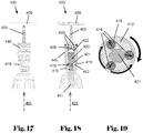
- Fig. 17
- illustrates a screw-setting device in a fourth embodiment during a setting process,
- Fig. 18
- illustrates the screw-setting device of
Fig. 17 during a setting process in a cross-sectional view, - Fig. 19
- illustrates the screw-setting device of
Fig. 17 during a setting process in another cross-sectional view, - Fig. 20
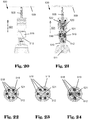
- illustrates a screw-setting device in a fifth embodiment during a setting process,
- Fig. 21
- illustrates the screw-setting device of
Fig. 20 during a setting process in a cross-sectional view, - Fig. 22
- illustrates the screw-setting device of
Fig. 20 during a setting process in another cross-sectional view, - Fig. 23
- illustrates the screw-setting device of
Fig. 22 at a later stage during the setting process, - Fig. 24
- illustrates a screw-setting device in a sixth embodiment in a cross-sectional view,
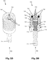
- Fig. 25
- illustrates a screw-setting device in a seventh embodiment, and
- Fig. 26
- illustrates the screw-setting device of
Fig. 25 in a cross-sectional view. - In
Figs. 1 to 12 , a screw-settingdevice 100 for temporarily holding ascrew 105 which has ahead 106, and for driving thescrew 105 in aforward direction 101 into aworkpiece 109, is shown. The screw-settingdevice 100 is implemented in apower screw driver 102 which comprises atorque output 103 formed as a chuck and a power drive (not shown) rotationally driving thetorque output 103. The screw-settingdevice 100 comprises aninput element 110 having a torque-inputtingsection 111 and a torque-transmittingsection 112. The torque-inputtingsection 111 is received in and mounted to thetorque output 103 to receive torque from thetorque output 103 when thepower screw driver 102 is rotationally driven. The screw-settingdevice 100 further comprises anoutput element 120 having a torque-receivingsection 121 formed as a shaft extending in a direction opposite to theforward direction 101 and a screw-drivingsection 122 formed as a nut receiving thehead 106 of thescrew 105. Thehead 106 comprises ascrew drive 107 formed as an external Hex drive and fitting to the screw-drivingsection 122 which has an internal Hex shape and faces into theforward direction 101. In non-shown embodiments, the screw drive is formed as a Phillips, internal Hex, external or internal square, Torx or similar drive, enabling rotatingly driving the screw by the screw-driving section. - The torque-receiving
section 121 has an external Hex shape and is received in and engages the torque-transmittingsection 112 which has an internal Hex shape. In non-shown embodiments, the torque-transmitting section is received in the torque-receiving section or the shape is a square or triangle or similar shape deviating from a circular shape such that the torque-receivingsection 121 receives a torque from the torque-transmittingsection 112. Due to the corresponding shapes of the torque-receivingsection 121 and the torque-transmittingsection 112, the torque-receivingsection 121 is displaceable in theforward direction 101 with respect to the torque-transmittingsection 112 between a forward position (as shown inFigs. 4, 5 ,11, 12 ) and a rearward position (as shown inFig. 10 ). - As e.g. shown in
Fig. 6 , theinput element 110 comprises arear stop 115 facing in theforward direction 101 and limiting a displacement of theoutput element 120 into a rearward direction opposite to the forward direction with respect to theinput element 110. Further, theinput element 110 comprises afront stop 116 facing in the rearward direction and limiting a displacement of theoutput element 120 into theforward direction 101 with respect to theinput element 110. To this end, theoutput element 120 comprises acounter stop 124 facing in theforward direction 101 and formed as a press-on ring or similar radial protrusion. - The screw-setting
device 100 further comprises anoutput spring 125 formed as coil spring and supported by theinput element 110 and biasing theoutput element 120 into the forward position. To this end, theinput element 110 comprises aninternal shoulder 113 facing in theforward direction 101 and theoutput element 120 comprises anexternal shoulder 123 facing in the opposite direction, and theoutput spring 125 is supported between theinternal shoulder 113 and theexternal shoulder 123. - The screw-setting
device 100 comprises a pair of retainingelements 130 formed as pins having a longitudinal shape defining alongitudinal axis 131 which is perpendicular to theforward direction 101. Each of the retainingelements 130 is movable along a travel path guided by aguide 132 formed as two slots provided in theinput element 110. As shown inFigs. 2, 3 , the travel path is curved. The retainingelements 130 are movable between a retaining position (as shown inFigs. 2 ,6 ,8, 9 ) and a clearance position (as shown inFigs. 1 ,4 ,5 ,10, 11, 12 ). In the retaining position, the retainingelements 130 are located in a pathway of the screw-drivingsection 122 along theforward direction 101, and in the clearance position, the retainingelements 130 are located outside the pathway of the screw-drivingsection 122 along theforward direction 101. - The screw-setting
device 100 further comprises alocking element 140 formed as an outer sleeve embracing theinput element 110 and extending in theforward direction 101 past theinput element 110 and theoutput element 120. The lockingelement 140 is movable along theforward direction 101 between a locking position (as shown inFigs. 6 ,8, 9 ) and a releasing position (as shown inFigs. 1 ,4 ,5 ,10, 11, 12 ). In the locking position, the lockingelement 140 locks the retainingelements 130 in the retaining position, and in the releasing position, the lockingelement 140 releases a movement of the retainingelements 130 from the retaining position to the clearance position. The screw-settingdevice 100 comprises alocking spring 145 supported by theinput element 110 and biasing thelocking element 140 into the locking position. To this end, theinput element 110 comprises anexternal shoulder 114 facing in theforward direction 101, and thelocking spring 145 is supported between theexternal shoulder 114 and aback end 141 of thelocking element 140 facing in the opposite direction. - The locking
element 140 comprises a compulsory guide forcing each of the retainingelements 130 along its respective travel path. To this end, the compulsory guide comprises first and second slots extending radially through the lockingelement 140 at opposite lateral sides of thelocking element 140. The first and second slots are protected against dust by acover 142 formed as a ring element, such as an O-ring, embracing thelocking element 140 and received in a circumferential groove provided at thelocking element 140. Each of the retainingelements 130 comprises a firstlongitudinal end section 133 and a secondlongitudinal end section 134 opposite to the firstlongitudinal end section 133. The first and secondlongitudinal end sections elements 130 can move with respect to thelocking element 140 only along the first and second slots. The first and second slots both have an orientation perpendicular to the forward direction. Accordingly, any movement by the lockingelement 140 along the forward direction forces the retainingelements 130 along theguide 132. - In
Figs. 4 to 6 , a possible way of loading thescrew 105 into the screw-settingdevice 100 is shown. In a first step, thescrew 105 approaches the screw-settingdevice 100 in a direction opposite to the forward direction 101 (Fig. 4 ). Under the biasing force of thelocking spring 145, the lockingelement 140 forces the retainingelements 130 radially inwards against the screw-drivingsection 122 of theoutput element 120 which keeps the retainingelements 130 in the clearance position. Subsequently, thehead 106 of thescrew 105 is inserted into the screw-drivingsection 122 of the output element 120 (Fig. 5 ). At this time, thedriving section 122 of theoutput element 120 still keeps the retainingelements 130 in the clearance position. - In a final step, the
screw 105 and, together with it, theoutput element 120 are pushed in a direction opposite the forward direction 101 (downwards inFigs. 4-6 ) with respect to theinput element 110 against the biasing force of theoutput spring 125. When the retainingelements 130 are in front of the screw-drivingsection 122 and thehead 106 of thescrew 105, the retainingelements 130 move into the retaining position under the biasing force of thelocking spring 145 which acts on the locking element 140 (Fig. 6 ). Thescrew 105 is then temporarily secured in the screw-settingdevice 100. - In
Figs. 7 to 12 , a possible way of setting thescrew 105 into theworkpiece 109 is shown. In a first step (Fig. 7 ), thepower screw driver 102 and, together with it, the screw-settingdevice 100 and thescrew 105, are pressed in theforward direction 101 against theworkpiece 109. In a subsequent step (Fig. 8 ), thepower screw driver 102 is triggered to rotationally drive thetorque output 103. Torque and rotation are thereby transmitted from thetorque output 103 to theinput element 110, from theinput element 110 to theoutput element 120, and from theoutput element 120 to thescrew 105. - The rotation of the
screw 105 which is still pressed against theworkpiece 109, causes thescrew 105 to penetrate theworkpiece 109. In the embodiment shown, thescrew 105 is formed as a self-drilling and self-tapping screw. During penetration, thescrew 105, and together with it, the screw-settingdevice 100 continuously move in theforward direction 101. - When the
locking element 140 contacts the workpiece 109 (Fig. 9 ), the lockingelement 140 stops moving in theforward direction 101 and begins moving with respect to theinput element 110 in a direction opposite to theforward direction 101, thereby compressing thelocking spring 145. The relative movement between the lockingelement 140 and theinput element 110 causes the retainingelements 130 to move along theguides 132 from the retaining position onto the clearance position, i.e. away from the screw 105 (Fig. 10 ). When the retainingelements 130 are in the clearance position (Fig. 11 ), thescrew 105 can freely travel further in theforward direction 101. Even though theinput element 110 contacts theworkpiece 109 at this time, theoutput element 120 can follow thescrew 105 and drive thescrew 105 into theworkpiece 109 until thehead 106 of thescrew 105 contacts theworkpiece 109. - In a final step (
Fig. 12 ), after thescrew 105 has been tightened, the power screw driver and, together with it, the screw-settingdevice 100 are lifted from theworkpiece 109. At this time, the retainingelements 130 are kept in the clearance position by the screw-drivingsection 122 of theoutput element 120, and another screw can be loaded in the screw-settingdevice 100, as shown inFigs. 4-6 . Furthermore, the above-described process is reversible by applying the process steps in the reverse order, to remove thescrew 105 from theworkpiece 109 back into the locked position shown inFigs. 6-8 . - In
Figs. 13 to 15 , a screw-settingdevice 200 for temporarily holding ascrew 205 which has ahead 206, and for driving thescrew 205 in aforward direction 201 into aworkpiece 209, is shown. The screw-settingdevice 200 comprises similar parts having similar functions as compared to the screw-settingdevice 100 shown inFigs. 1 to 12 . Specifically, the screw-settingdevice 200 comprises aninput element 210 having a torque-inputtingsection 211, a torque-transmittingsection 212 and arear stop 215, anoutput element 220 having a torque-receivingsection 221 and a screw-drivingsection 222 receiving thehead 206 of thescrew 205, anoutput spring 225 biasing theoutput element 220 into the forward position, a pair of retainingelements 230, aguide 232 for the retaining elements, alocking element 240, alocking spring 245 biasing thelocking element 240 into the locking position. - In addition, the screw-setting
device 200 comprises a press-onelement 250 formed as a sleeve freely rotatable mounted to thelocking element 240 and thus indirectly to theinput element 210 and thus freely rotatable about theforward direction 201 with respect to the screw-drivingsection 222 of theoutput element 220. The press-onelement 250 comprises a press-onface 251 facing into theforward direction 201 and protruding past the screw-drivingsection 222 of theoutput element 220 into theforward direction 201. The press-onface 251 is made of a soft and smooth material, such as rubber or plastic, to avoid scratches on theworkpiece 209. Also, since the press-onelement 250 is freely rotatable with respect to theinput element 210, it can be pressed on theworkpiece 209 without rotating about theforward direction 201. - Further, the screw-setting
device 200, in particular theinput element 210 comprises anadjustment element 260 formed as a wheel or dial. Theadjustment element 260 comprises afront stop 216 facing in a direction opposite to theforward direction 201 and limiting a displacement of theoutput element 220 into theforward direction 201 with respect to theinput element 210. To this end, theoutput element 220 comprises acounter stop 224 facing in theforward direction 201. Theadjustment element 260 is capable of adjusting a position, along theforward direction 201, of thefront stop 216 on theinput element 210. To this end, theadjustment element 260 comprises athread 261 and theinput element 210 comprises a counter-thread 217 which is in engagement with thethread 261 such that rotation of theadjustment element 260 about theforward direction 201 causes theadjustment element 260 and, together with it, thefront stop 216 to move along theforward direction 201. In this way, a travel path along theforward direction 201 of the output element and thus a setting depth of thescrew 205 can be adjustably limited by theadjustment element 260. - As shown in
Fig. 14 , if theadjustment element 260 is in its frontmost position, theoutput element 220 is able to follow thescrew 205 until it is tightly fastened at theworkpiece 209. As shown inFig. 15 , if theadjustment element 260 is in a rear position, a pathway of theoutput element 220 along theforward direction 201 is limited and theoutput element 220 releases thescrew 205 before it is over-tightened. - In
Fig. 16 , a screw-settingdevice 300 for temporarily holding ascrew 305 which has ahead 306, and for driving thescrew 305 in aforward direction 301 into aworkpiece 309, is shown. The screw-settingdevice 300 comprises similar parts having similar functions as compared to the screw-settingdevice 100 shown inFigs. 1 to 12 or the screw-settingdevice 200 shown inFigs. 13 to15. Specifically, the screw-settingdevice 300 comprises aninput element 310 having a torque-inputtingsection 311, a torque-transmittingsection 312 and arear stop 315, anoutput element 320 having a torque-receivingsection 321 and a screw-drivingsection 322 receiving thehead 306 of thescrew 305, anoutput spring 325 biasing theoutput element 320 into the forward position, a pair of retainingelements 330, alocking element 340, alocking spring 345 biasing thelocking element 340 into the locking position, and anadjustment element 360. - Each of the retaining
elements 330 is movable along a travel path guided by aguide 332 formed as two slots provided in theinput element 310. As shown inFig. 16 , the travel path is straight and inclined with respect to theforward direction 301 by 45°. In non-shown embodiments, the travel path of one or more retaining elements is inclined with respect to the forward direction by different angles, such as e.g. 30° or 60°. The lockingelement 340 comprises a compulsory guide forcing each of the retainingelements 330 along its respective travel path. To this end, the compulsory guide comprises first andsecond slots 343 extending radially through the lockingelement 340 at opposite lateral sides of thelocking element 340. As shown inFig. 16 , the first andsecond slots 343 are straight and inclined with respect to theforward direction 301 by 45°. In non-shown embodiments, the compulsory guide is curved and/oder inclined with respect to the forward direction by different angles, such as e.g. 30° or 60°. - In
Figs. 17 to 19 , a screw-settingdevice 400 for temporarily holding ascrew 405 which has ahead 406, and for driving thescrew 405 in aforward direction 401 into aworkpiece 409, is shown. The screw-settingdevice 400 comprises similar parts having similar functions as compared to the screw-settingdevice 100 shown inFigs. 1 to 12 . Specifically, the screw-settingdevice 400 comprises aninput element 410 having a torque-inputtingsection 411, a torque-transmittingsection 412, anoutput element 420 having a torque-receivingsection 421 and a screw-drivingsection 422 receiving thehead 406 of thescrew 405, a pair of retainingelements 430, and alocking element 440. - In a plane perpendicular to the
forward direction 401, the torque-receivingsection 421 of theoutput element 420 has a hexagonal contour, and the torque-transmittingsection 412 of theinput element 410 comprises three torque-transmission elements 418 formed as balls made of metal and movable between a torque-transmitting position (as shown inFig. 18 ) and a torque-free position (as shown inFig. 19 ). In the torque-transmitting position, the torque-transmission elements 418 are in engagement with the hexagonal contour of the torque-receivingsection 421, and in the torque-free position, the torque-transmission elements 418 are out of engagement with the hexagonal contour of the torque-receivingsection 421. - The screw-setting
device 400 further comprises a torque-limit spring 419 formed as an open ring made of metal supported by theinput element 410 and biasing the torque-transmission elements 418 into the torque-transmitting position. When a torque transmitted from the torque-transmittingsection 412 to the torque-transmission elements 418 which is greater than a threshold torque that is defined by the strength of the torque-limit spring 419, then the torque-transmission elements 418 are forced radially outwards into the torque-free position against the biasing force of the torque-limit spring 419 which then bends outwards (as shown inFig. 19 ), and the transmitted torque does not increase any further. The threshold torque is thus a torque limit for the setting of thescrew 405. - In
Figs. 20 to 23 , a screw-settingdevice 500 for temporarily holding ascrew 505, and for driving thescrew 505 in aforward direction 501 into aworkpiece 509, is shown. The screw-settingdevice 500 comprises similar parts having similar functions as compared to the screw-settingdevice 400 shown inFigs. 17 to 19 . Specifically, the screw-settingdevice 500 comprises aninput element 510 having a torque-inputtingsection 511, a torque-transmittingsection 512, anoutput element 520 having a torque-receivingsection 521 which has a hexagonal contour and a screw-drivingsection 522 receiving the head 506 of thescrew 505, and a torque-limit spring 519. - The torque-transmitting
section 512 of theinput element 510 comprises six torque-transmission elements 518 formed as pins made of metal and movable between a torque-transmitting position (as shown inFig. 22 ) and a torque-free position (as shown inFig. 23 ). The torque-transmission elements 518 each have a pin-longitudinal direction oriented in parallel to theforward direction 501. In the torque-transmitting position, the torque-transmission elements 518 are in engagement with the hexagonal contour of the torque-receivingsection 521, and in the torque-free position, the torque-transmission elements 518 are out of engagement with the hexagonal contour of the torque-receivingsection 521. - In
Fig. 24 , an embodiment of a screw-setting device 600 is shown, which is modified with respect to the screw-settingdevice 500 shown inFigs. 20 to 23 in that the torque-receivingsection 621 has a square contour or cross section and the torque-transmittingsection 612 comprises four torque-transmission elements 618 formed as balls or pins which are biased against the torque-receivingsection 621 by a torque-limit spring 619. - In
Figs. 25 to 26 , a screw-settingdevice 700 for temporarily holding ascrew 705 and for driving thescrew 705 in aforward direction 701 into a workpiece, is shown. The screw-settingdevice 700 comprises similar parts having similar functions as compared to the screw-settingdevice 100 shown inFigs. 1 to 12 . Specifically, the screw-settingdevice 700 comprises aninput element 710 having a torque-inputtingsection 711, a torque-transmittingsection 712 and arear stop 715, anoutput element 720 having a torque-receivingsection 721 and a screw-drivingsection 722 receiving thescrew 705, anoutput spring 725 biasing theoutput element 720 into the forward position, - The screw-setting
device 700 comprises six retainingelements 730 formed as balls having a spherical shape. Each of the retainingelements 730 is movable along a travel path guided by aguide 732 formed as a bore provided in theinput element 710. As shown inFig. 26 , the travel path is straight. The retainingelements 730 are movable between a retaining position (as shown inFigs. 25, 26 ) and a clearance position (not shown). In the retaining position, the retainingelements 730 are located in a pathway of the screw-drivingsection 722 along theforward direction 701, and in the clearance position, the retainingelements 730 are located outside the pathway of the screw-drivingsection 722 along theforward direction 701. - The screw-setting
device 700 further comprises alocking element 740 formed as an outer sleeve embracing theinput element 710 and extending in theforward direction 701 past theinput element 710 and theoutput element 720. The lockingelement 740 is movable along theforward direction 701 between a locking position (as shown inFigs. 25, 26 ) and a releasing position (not shown). In the locking position, the lockingelement 740 locks the retainingelements 730 in the retaining position, and in the releasing position, the lockingelement 740 releases a movement of the retainingelements 730 from the retaining position to the clearance position. The screw-settingdevice 100 comprises alocking spring 745 supported by theinput element 710 and biasing thelocking element 740 into the locking position. The lockingelement 740 is secured against falling off the device by a securingelement 746 formed as a spring-lock washer. - The foregoing description of exemplary embodiments of the invention have been presented for purposes of illustration and of description. It is not intended to be exhaustive or to limit the invention to the precise form disclosed, and modifications and variations are possible in light of the above teachings or may be acquired from practice of the invention. The functionality described may be distributed among modules that differ in number and distribution of functionality from those described herein. Additionally, the order of execution of the functions may be changed depending on the embodiment. The embodiments were chosen and described in order to explain the principles of the invention and as practical applications of the invention to enable one skilled in the art to utilize the invention in various embodiments and with various modifications as suited to the particular use contemplated. It is intended that the scope of the invention be defined by the claims appended hereto and their equivalents.
Claims (15)
- A screw-setting device for temporarily holding a screw having a head, comprising an input element having a torque-inputting section and a torque-transmitting section, and a torque-output element having a torque-receiving section and a screw-driving section facing into a forward direction, wherein the torque-receiving section engages the torque-transmitting section to receive a torque from the torque-transmitting section, and wherein the torque-receiving section is displaceable in the forward direction with respect to the torque-transmitting section between a forward position and a rearward position.
- A screw-setting device according to claim 1, wherein the input element comprises a rear stop limiting a displacement of the output element into a rearward direction opposite to the forward direction with respect to the input element.
- A screw-setting device according to any of the preceding claims, wherein the input element comprises a front stop limiting a displacement of the output element into the forward direction with respect to the input element.
- A screw-setting device according to claim 3, further comprising an adjustment element for adjusting a position, along the forward direction, of the front stop on the input element.
- A screw-setting device according to claim 4, wherein the adjustment element comprises the front stop and a thread, and wherein the input element comprises a counter-thread which is in engagement with the thread.
- A screw-setting device according to any of the preceding claims, further comprising an output spring supported by the input element and biasing the output element into the forward position.
- A screw-setting device according to any of the preceding claims, further comprising a retaining element movable between a retaining position and a clearance position, wherein in the retaining position, the retaining element is located in a pathway of the screw-driving section along the forward direction, and wherein in the clearance position, the retaining element is located outside the pathway of the screw-driving section along the forward direction.
- A screw-setting device according to claim 7, further comprising a locking element movable between a locking position and a releasing position, wherein in the locking position, the locking element locks the retaining element in the retaining position, and wherein in the releasing position, the locking element releases a movement of the retaining element from the retaining position to the clearance position.
- A screw-setting device according to claim 8, further comprising a locking spring supported by the input element and biasing the locking element into the locking position.
- A screw-setting device according to any of the preceding claims, wherein in a plane perpendicular to the forward direction, the torque-receiving section of the output element has a non-circular circumferential contour, and wherein the torque-transmitting section of the input element comprises a torque-transmission element movable between a torque-transmitting position and a torque-free position, wherein in the torque-transmitting position, the torque-transmission element is in engagement with the non-circular circumferential contour of the torque-receiving section, and wherein in the torque-free position, the torque-transmission element is out of engagement with the non-circular circumferential contour of the torque-receiving section.
- A screw-setting device according to claim 10, further comprising a torque-limit spring supported by the input element and biasing the torque-transmission element into the torque-transmitting position.
- A screw-setting device according to any of claims 10 and 11, wherein the torque-transmission element comprises a ball.
- A screw-setting device according to any of claims 10 and 11, wherein the torque-transmission element comprises a pin having a pin-longitudinal direction oriented in parallel to the forward direction.
- A screw-setting device according to any of the preceding claims, further comprising a press-on element mounted to the input element and freely rotatable about the forward direction with respect to the input element, wherein the press-on element comprises a press-on face facing into the forward direction and protruding past the input element into the forward direction.
- A power screw driver, comprising a torque output, a power drive rotationally driving the torque output, and a screw-setting device according to any of the preceding claims mounted to the torque output to receive torque from the torque output.
Priority Applications (2)
| Application Number | Priority Date | Filing Date | Title |
|---|---|---|---|
| EP20176946.0A EP3915729A1 (en) | 2020-05-27 | 2020-05-27 | Screw-setting device and power screw driver |
| PCT/EP2021/063139 WO2021239511A1 (en) | 2020-05-27 | 2021-05-18 | Screw-setting device and power screw driver |
Applications Claiming Priority (1)
| Application Number | Priority Date | Filing Date | Title |
|---|---|---|---|
| EP20176946.0A EP3915729A1 (en) | 2020-05-27 | 2020-05-27 | Screw-setting device and power screw driver |
Publications (1)
| Publication Number | Publication Date |
|---|---|
| EP3915729A1 true EP3915729A1 (en) | 2021-12-01 |
Family
ID=70918229
Family Applications (1)
| Application Number | Title | Priority Date | Filing Date |
|---|---|---|---|
| EP20176946.0A Withdrawn EP3915729A1 (en) | 2020-05-27 | 2020-05-27 | Screw-setting device and power screw driver |
Country Status (2)
| Country | Link |
|---|---|
| EP (1) | EP3915729A1 (en) |
| WO (1) | WO2021239511A1 (en) |
Citations (5)
| Publication number | Priority date | Publication date | Assignee | Title |
|---|---|---|---|---|
| DE29703606U1 (en) * | 1997-02-28 | 1998-06-25 | Wera Werk Hermann Werner GmbH & Co., 42349 Wuppertal | Chuck for screwdriver bits |
| US6364318B1 (en) * | 1999-08-13 | 2002-04-02 | Maxtech Manufacturing Inc. | Device for holding a tool bit and selectively transmitting or releasing torque between a torque generating means and the tool bit |
| EP2283974A1 (en) * | 2009-08-12 | 2011-02-16 | Black & Decker Inc. | Tool Bit or Tool Holder for Power Tool |
| US20150298304A1 (en) * | 2014-04-16 | 2015-10-22 | Yi-Fu Chen | Socket wrench with retaining mechanism |
| US20190054602A1 (en) * | 2017-08-15 | 2019-02-21 | Honda Motor Co., Ltd. | Fastener holder tool and method |
-
2020
- 2020-05-27 EP EP20176946.0A patent/EP3915729A1/en not_active Withdrawn
-
2021
- 2021-05-18 WO PCT/EP2021/063139 patent/WO2021239511A1/en not_active Ceased
Patent Citations (5)
| Publication number | Priority date | Publication date | Assignee | Title |
|---|---|---|---|---|
| DE29703606U1 (en) * | 1997-02-28 | 1998-06-25 | Wera Werk Hermann Werner GmbH & Co., 42349 Wuppertal | Chuck for screwdriver bits |
| US6364318B1 (en) * | 1999-08-13 | 2002-04-02 | Maxtech Manufacturing Inc. | Device for holding a tool bit and selectively transmitting or releasing torque between a torque generating means and the tool bit |
| EP2283974A1 (en) * | 2009-08-12 | 2011-02-16 | Black & Decker Inc. | Tool Bit or Tool Holder for Power Tool |
| US20150298304A1 (en) * | 2014-04-16 | 2015-10-22 | Yi-Fu Chen | Socket wrench with retaining mechanism |
| US20190054602A1 (en) * | 2017-08-15 | 2019-02-21 | Honda Motor Co., Ltd. | Fastener holder tool and method |
Also Published As
| Publication number | Publication date |
|---|---|
| WO2021239511A1 (en) | 2021-12-02 |
Similar Documents
| Publication | Publication Date | Title |
|---|---|---|
| US4883130A (en) | Dual speed transmission for automatic assembly machine | |
| US3396765A (en) | Screw and driver | |
| US10974310B2 (en) | Automatic double-action fastener installation tool | |
| US4237946A (en) | Chuck for holding and driving fasteners, such as screws or nails | |
| US7488135B2 (en) | Fastening device | |
| US9815180B2 (en) | Torque transmission driver | |
| US3869942A (en) | Driving tool | |
| US5517742A (en) | Method of setting a joint including a torque limited fastener | |
| CZ295970B6 (en) | Fastening system components for transmitting torque and forming tool for making them | |
| US4631992A (en) | Screwdriver | |
| KR20020077796A (en) | Blind fastener and drive nut assembly | |
| CN1053570A (en) | The erecting tools of improved helical coil inserts | |
| US10525571B2 (en) | Screwdriver and ratchet mechanism thereof | |
| US12447591B1 (en) | Torque driver | |
| US9022137B2 (en) | Fastening tool | |
| US20090151519A1 (en) | Dual socket for fast pace assembly environment | |
| US4742735A (en) | Driver for a lobed collar | |
| US5224402A (en) | Screw and screwdriver therefor | |
| EP3915729A1 (en) | Screw-setting device and power screw driver | |
| EP3915728A1 (en) | Screw-setting device and power screw driver | |
| US4747204A (en) | Method of installing drive nut blind fasteners with cap nuts | |
| US20200109724A1 (en) | Clamping hub | |
| JPS6283507A (en) | Blank clamping tool and clamping method thereof | |
| US10792793B2 (en) | Tool bits with floating magnet sleeves | |
| US6237450B1 (en) | Fastener system with spline recess and driving tool |
Legal Events
| Date | Code | Title | Description |
|---|---|---|---|
| PUAI | Public reference made under article 153(3) epc to a published international application that has entered the european phase |
Free format text: ORIGINAL CODE: 0009012 |
|
| STAA | Information on the status of an ep patent application or granted ep patent |
Free format text: STATUS: THE APPLICATION HAS BEEN PUBLISHED |
|
| AK | Designated contracting states |
Kind code of ref document: A1 Designated state(s): AL AT BE BG CH CY CZ DE DK EE ES FI FR GB GR HR HU IE IS IT LI LT LU LV MC MK MT NL NO PL PT RO RS SE SI SK SM TR |
|
| B565 | Issuance of search results under rule 164(2) epc |
Effective date: 20201120 |
|
| STAA | Information on the status of an ep patent application or granted ep patent |
Free format text: STATUS: THE APPLICATION IS DEEMED TO BE WITHDRAWN |
|
| 18D | Application deemed to be withdrawn |
Effective date: 20220602 |