EP3913520A1 - Aviation blade profile chord length measurement method and system based on secant rotation iteration - Google Patents
Aviation blade profile chord length measurement method and system based on secant rotation iteration Download PDFInfo
- Publication number
- EP3913520A1 EP3913520A1 EP20904296.9A EP20904296A EP3913520A1 EP 3913520 A1 EP3913520 A1 EP 3913520A1 EP 20904296 A EP20904296 A EP 20904296A EP 3913520 A1 EP3913520 A1 EP 3913520A1
- Authority
- EP
- European Patent Office
- Prior art keywords
- secant
- point set
- points
- chord length
- blade
- Prior art date
- Legal status (The legal status is an assumption and is not a legal conclusion. Google has not performed a legal analysis and makes no representation as to the accuracy of the status listed.)
- Granted
Links
Images

Classifications
-
- F—MECHANICAL ENGINEERING; LIGHTING; HEATING; WEAPONS; BLASTING
- F01—MACHINES OR ENGINES IN GENERAL; ENGINE PLANTS IN GENERAL; STEAM ENGINES
- F01D—NON-POSITIVE DISPLACEMENT MACHINES OR ENGINES, e.g. STEAM TURBINES
- F01D5/00—Blades; Blade-carrying members; Heating, heat-insulating, cooling or antivibration means on the blades or the members
- F01D5/12—Blades
- F01D5/14—Form or construction
- F01D5/141—Shape, i.e. outer, aerodynamic form
-
- F—MECHANICAL ENGINEERING; LIGHTING; HEATING; WEAPONS; BLASTING
- F04—POSITIVE - DISPLACEMENT MACHINES FOR LIQUIDS; PUMPS FOR LIQUIDS OR ELASTIC FLUIDS
- F04D—NON-POSITIVE-DISPLACEMENT PUMPS
- F04D27/00—Control, e.g. regulation, of pumps, pumping installations or pumping systems specially adapted for elastic fluids
- F04D27/001—Testing thereof; Determination or simulation of flow characteristics; Stall or surge detection, e.g. condition monitoring
-
- F—MECHANICAL ENGINEERING; LIGHTING; HEATING; WEAPONS; BLASTING
- F04—POSITIVE - DISPLACEMENT MACHINES FOR LIQUIDS; PUMPS FOR LIQUIDS OR ELASTIC FLUIDS
- F04D—NON-POSITIVE-DISPLACEMENT PUMPS
- F04D29/00—Details, component parts, or accessories
- F04D29/26—Rotors specially for elastic fluids
- F04D29/32—Rotors specially for elastic fluids for axial flow pumps
- F04D29/321—Rotors specially for elastic fluids for axial flow pumps for axial flow compressors
- F04D29/324—Blades
-
- F—MECHANICAL ENGINEERING; LIGHTING; HEATING; WEAPONS; BLASTING
- F05—INDEXING SCHEMES RELATING TO ENGINES OR PUMPS IN VARIOUS SUBCLASSES OF CLASSES F01-F04
- F05D—INDEXING SCHEME FOR ASPECTS RELATING TO NON-POSITIVE-DISPLACEMENT MACHINES OR ENGINES, GAS-TURBINES OR JET-PROPULSION PLANTS
- F05D2240/00—Components
- F05D2240/20—Rotors
- F05D2240/30—Characteristics of rotor blades, i.e. of any element transforming dynamic fluid energy to or from rotational energy and being attached to a rotor
- F05D2240/301—Cross-sectional characteristics
-
- F—MECHANICAL ENGINEERING; LIGHTING; HEATING; WEAPONS; BLASTING
- F05—INDEXING SCHEMES RELATING TO ENGINES OR PUMPS IN VARIOUS SUBCLASSES OF CLASSES F01-F04
- F05D—INDEXING SCHEME FOR ASPECTS RELATING TO NON-POSITIVE-DISPLACEMENT MACHINES OR ENGINES, GAS-TURBINES OR JET-PROPULSION PLANTS
- F05D2250/00—Geometry
- F05D2250/70—Shape
- F05D2250/74—Shape given by a set or table of xyz-coordinates
-
- F—MECHANICAL ENGINEERING; LIGHTING; HEATING; WEAPONS; BLASTING
- F05—INDEXING SCHEMES RELATING TO ENGINES OR PUMPS IN VARIOUS SUBCLASSES OF CLASSES F01-F04
- F05D—INDEXING SCHEME FOR ASPECTS RELATING TO NON-POSITIVE-DISPLACEMENT MACHINES OR ENGINES, GAS-TURBINES OR JET-PROPULSION PLANTS
- F05D2260/00—Function
- F05D2260/80—Diagnostics
-
- G—PHYSICS
- G06—COMPUTING OR CALCULATING; COUNTING
- G06F—ELECTRIC DIGITAL DATA PROCESSING
- G06F30/00—Computer-aided design [CAD]
- G06F30/10—Geometric CAD
- G06F30/15—Vehicle, aircraft or watercraft design
-
- G—PHYSICS
- G06—COMPUTING OR CALCULATING; COUNTING
- G06F—ELECTRIC DIGITAL DATA PROCESSING
- G06F30/00—Computer-aided design [CAD]
- G06F30/10—Geometric CAD
- G06F30/17—Mechanical parametric or variational design
Definitions
- the present invention relates to the field of profile inspection of an aero-engine blade, and in particular to a method and system for determining and calculating a profile chord length of an aero-engine blade based on secant rotation iteration.
- An aero-engine blade is a core component of an aero-engine.
- the aero-engine blade works under the severe conditions of high temperature, high pressure and fluctuating load for a long time.
- the manufacturing precision of the aero-engine blade directly affects the performance of the aero-engine, so that it is necessary to inspect and control the profile quality of the aero-engine blade.
- As the chord length is the key parameter of an aero-engine blade profile, it is particularly important to calculate the chord length accurately.
- chord length When the chord length is directly measured, it is difficult to determine the position of a chord line and ensure the tangency of a pressure surface side and the leading and trailing edges and there are too many parameters to be measured, directly resulting in low measurement efficiency.
- the profile chord length of the aero-engine blade is calculated at present generally based on a method for creating a convex hull of a blade profile.
- a convex hull structure is complex and for an aero-engine blade with a small radius of the leading edge and the trailing edge, it is possible to directly delete part of measuring points since the leading and trailing edge measuring points are close. As a result the created convex hull structure is wrong, causing calculation errors of the chord length.
- the size of the blade can be controlled by the chord length of the blade. If the chord length is too short, the strength of the blade is reduced, affecting the impact resistance and the aerodynamic performance of the blade. Therefore, the prior art has the technical problem that the aerodynamic performance and safety of the blade cannot be ensured due to numerous calculation errors in the determination of the chord length.
- the present invention provides a method and system for determining and calculating a profile chord length of an aero-engine blade based on secant rotation iteration, thereby solving the technical problem that the aerodynamic performance and safety of the blade cannot be ensured due to numerous calculation errors of the chord length in the prior art.
- a method for determining and calculating a profile chord length of an aero-engine blade based on secant rotation iteration includes the following steps:
- the method may further include: comparing the chord length calculated in step (2) with a standard chord length, wherein when a difference between the chord length and the standard chord length is less than a preset value, the aerodynamic performance and safety of the blade meet the requirements.
- step (1) may include:
- intersection points of the secant and the blade profile There are 2 or 3 or 4 intersection points of the secant and the blade profile.
- the two middle points when the four intersection points are connected, are the intersection points of the secant and the pressure surface.
- the secant is rotated to obtain the intersection point of the secant and the pressure surface.
- the secant is translated to obtain the intersection point of the secant and the pressure surface.
- step (2) may include:
- step (2) may include:
- a system for determining and calculating a profile chord length of an aero-engine blade based on secant rotation iteration includes:
- the system may include: a blade performance evaluation module, configured to compare the chord length calculated by the secant rotation module with a standard chord length, wherein when an error between the chord length and the standard chord length is less than a preset value, the aerodynamic performance and safety of the blade meet requirements.
- a blade performance evaluation module configured to compare the chord length calculated by the secant rotation module with a standard chord length, wherein when an error between the chord length and the standard chord length is less than a preset value, the aerodynamic performance and safety of the blade meet requirements.
- the point set segmentation module may further include:
- a method for determining and calculating a profile chord length of an aero-engine blade based on secant rotation iteration includes the following steps:
- the method may further include: the chord length calculated in step (2) is compared with a standard chord length, wherein when a difference between the chord length and the standard chord length is less than a preset value, the aerodynamic performance and safety of the blade meet requirements.
- the secant when there are two intersection points of the secant and the blade profile, the secant is translated along a midperpendicular direction of the two points A and B until the secant is intersected with the blade profile at four points, wherein the points C and D are the intersection points of the secant and the pressure surface.
- the blade profile is segmented by the secant and the intersection point of the straight line and the pressure surface to obtain the leading edge point set and the trailing edge point set.
- the secant L divides the blade profile into two parts, the two parts and the point I can fall on the same side of the secant L and fall on the different sides of the secant L.
- (( y b - y a )( x i - x a ) + ( x a - x b )( y i - y a )) ⁇ S I > 0 ⁇ and P vary ⁇ p i ( x i , y i ) ⁇ P
- (( y b - y a )( x i - x ⁇ ) + ( x a - x b )( y i - y a )) ⁇ S I ⁇ 0, wherein S I ( y b - - a )
- ( y b - y a )(y i - y e ) + ( x b - x a )(x i - x e ) ⁇ 0 ⁇ and a trailing edge point set P t ⁇ p i (x i ,y i ) ⁇ P vary
- Step (2) may include:
- Alternativelystep (2) may include:
- the present invention takes one of the above as an example for detailed description.
- a distance d i y b ⁇ y a y ⁇ y e + x b ⁇ x a x ⁇ x e y b ⁇ y a 2 + x b ⁇ x a 2 from any point p i of P l and P t to the straight line T is calculated, and then the values of
- are sorted from the largest to the smallest to obtain an ordered leading edge point set P l ' A , A 1 , A 2 , ... , A m and an ordered trailing edge point set P t ' B , B 1 , B 2 , ... , B n .
- the method of the present invention is suitable for calculating the profile chord length of various types of aero-engine blades, that is, calculating the profile chord length of the aero-engine blade based on secant rotation iteration.
Landscapes
- Engineering & Computer Science (AREA)
- Mechanical Engineering (AREA)
- General Engineering & Computer Science (AREA)
- Physics & Mathematics (AREA)
- Fluid Mechanics (AREA)
- Turbine Rotor Nozzle Sealing (AREA)
- Agricultural Chemicals And Associated Chemicals (AREA)
- Structures Of Non-Positive Displacement Pumps (AREA)
- Image Analysis (AREA)
Abstract
Description
- The present invention relates to the field of profile inspection of an aero-engine blade, and in particular to a method and system for determining and calculating a profile chord length of an aero-engine blade based on secant rotation iteration.
- An aero-engine blade is a core component of an aero-engine. The aero-engine blade works under the severe conditions of high temperature, high pressure and fluctuating load for a long time.The manufacturing precision of the aero-engine blade directly affects the performance of the aero-engine, so that it is necessary to inspect and control the profile quality of the aero-engine blade. As the chord length is the key parameter of an aero-engine blade profile, it is particularly important to calculate the chord length accurately.
- When the chord length is directly measured, it is difficult to determine the position of a chord line and ensure the tangency of a pressure surface side and the leading and trailing edges and there are too many parameters to be measured, directly resulting in low measurement efficiency.
- During blade determination on a large scale, for the consideration of precision and efficiency, the profile chord length of the aero-engine blade is calculated at present generally based on a method for creating a convex hull of a blade profile. However, a convex hull structure is complex and for an aero-engine blade with a small radius of the leading edge and the trailing edge, it is possible to directly delete part of measuring points since the leading and trailing edge measuring points are close. As a result the created convex hull structure is wrong, causing calculation errors of the chord length.
- The size of the blade can be controlled by the chord length of the blade.If the chord length is too short, the strength of the blade is reduced, affecting the impact resistance and the aerodynamic performance of the blade. Therefore, the prior art has the technical problem that the aerodynamic performance and safety of the blade cannot be ensured due to numerous calculation errors in the determination of the chord length.
- For the above defects or improvement requirements in the prior art, the present invention provides a method and system for determining and calculating a profile chord length of an aero-engine blade based on secant rotation iteration, thereby solving the technical problem that the aerodynamic performance and safety of the blade cannot be ensured due to numerous calculation errors of the chord length in the prior art.
- To achieve the above objective, according to one aspect of the present invention, a method for determining and calculating a profile chord length of an aero-engine blade based on secant rotation iteration is provided. The method includes the following steps:
- (1) taking a connection line between two most distant points in a blade profile measuring point set as a secant, and rotating or translating the secant to enable the secant to intersect with a pressure surface, thus obtaining a leading edge point set and a trailing edge point set; and
- (2) rotating the secant in a range of the leading edge point set and the trailing edge point set to obtain tangent points of the secant and the leading and trailing edges, and calculating a distance between the two tangent points to obtain a chord length.
- The method may further include:
comparing the chord length calculated in step (2) with a standard chord length, wherein when a difference between the chord length and the standard chord length is less than a preset value, the aerodynamic performance and safety of the blade meet the requirements. - Further, step (1) may include:
- (11) collecting blade profile measuring points of the aero-engine blade to form a blade profile measuring point set, and taking a connecting line between two most distant points in the blade profile measuring point set as a secant;
- (12) rotating or translating the secant to enable the secant to intersect with a pressure surface at two points, and making a straight line perpendicular to the secant by using a midpoint of a connecting line of the two points to obtain an intersection point of the straight line and the pressure surface; and
- (13) segmenting a blade profile by the secant and the intersection point of the straight line and the pressure surface to obtain a leading edge point set and a trailing edge point set.
- Further, in the step (1), rotating or translating the secant to enable the secant to intersect with the pressure surface, may specifically be implemented as follows: coordinates (xi,yi ) of any point pi in the blade profile measuring point set are substituted into a linear equation of the secant to obtain Si = (yb - ya ) (xi - xa) + (xa - xb )(yi - ya ), wherein (xa,yb ) and (xb ,yb ) are two endpoints of the secant, and Si is a value obtained by substituting pi into the linear equation; Si is compared with a threshold δs, and when Si is less than the threshold δs, pi is an intersection point of the secant and the blade profile. There are 2 or 3 or 4 intersection points of the secant and the blade profile. When there are 4 intersection points of the secant and the blade profile, the two middle points, when the four intersection points are connected, are the intersection points of the secant and the pressure surface. When there are 3 intersection points of the secant and the blade profile, the secant is rotated to obtain the intersection point of the secant and the pressure surface. Further when there are 2 intersection points of the secant and the blade profile, the secant is translated to obtain the intersection point of the secant and the pressure surface. Further, the threshold

- Further, step (2) may include:
- (21) sorting the leading edge point set according to a distance between points in the leading edge point set and the straight line, and sorting the trailing edge point set according to a distance between points in the trailing edge point set and the straight line;
- (22) fixing an endpoint of the secant, and sequentially rotating the secant according to a sorting result in the trailing edge point set to obtain a tangent point of the secant and the trailing edge; and
- (23) fixing the tangent point of the secant and the trailing edge, sequentially rotating the secant according to a sorting result in the leading edge point set to obtain a tangent point of the secant and the leading edge, and calculating a distance between the two tangent points to obtain a chord length.
- Further, step (2) may include:
- (21) sorting the leading edge point set according to a distance between points in the leading edge point set and the straight line, and sorting the trailing edge point set according to a distance between points in the trailing edge point set and the straight line;
- (22) fixing an endpoint of the secant, and sequentially rotating the secant according to a sorting result in the leading edge point set to obtain a tangent point of the secant and the leading edge; and
- (23) fixing the tangent point of the secant and the leading edge, sequentially rotating the secant according to a sorting result in the trailing edge point set to obtain a tangent point of the secant and the trailing edge, and calculating a distance between the two tangent points to obtain a chord length.
- According to another aspect of the present invention, a system for determining and calculating a profile chord length of an aero-engine blade based on secant rotation iteration is provided. The system includes:
- a point set segmentation module, configured to take a connection line between two most disatant points in a blade profile measuring point set as a secant, rotate or translate the secant to enable the secant to intersect with a pressure surface, thus obtaining a leading edge point set and a trailing edge point set; and
- a secant rotation module, configured to rotate the secant in a range of the leading edge point set and the trailing edge point set to obtain tangent points of the secant and the leading and trailing edges, and calculate a distance between the two tangent points to obtain a chord length.
- Further, the system may include:
a blade performance evaluation module, configured to compare the chord length calculated by the secant rotation module with a standard chord length, wherein when an error between the chord length and the standard chord length is less than a preset value, the aerodynamic performance and safety of the blade meet requirements. - The point set segmentation module may further include:
- a first module, configured to collect blade profile measuring points of the aero-engine blade to form a blade profile measuring point set, and take a connecting line between two most distant points in the blade profile measuring point set as a secant;
- a second module, configured to rotate or translate the secant to enable the secant to intersect with the pressure surface at two points, and use a midpoint of a connecting line of the two points to make a straight line perpendicular to the secant to obtain an intersection point of the straight line and the pressure surface; and
- a third module, configured to segment a blade profile by the secant and the intersection point of the straight line and the pressure surface to obtain a leading edge point set and a trailing edge point set.
- In general, compared with the prior art, the above technical solution conceived in the present invention achieves the following beneficial effects.
- (1) According to the present invention, the connecting line between the two most distant points in the blade profile measuring point set is taken as the secant, and the secant is rotated or translated to intersect with the pressure surface to divide the point set; the secant is rotated in the range of the point set to obtain the tangent points of the secant and the leading and trailing edges, the distance between the two tangent points is calculated to obtain the chord length, so that the accuracy of the calculated chord length is high. Further the size of the blade can be controlled through the chord length of the blade. If the chord length is too short, the strength of the blade is reduced, the impact resistance and the aerodynamic performance of the blade are further affected, and thus the aerodynamic performance and safety of the blade can be guaranteed when the chord length of the blade is determined through the pesent method.
- (2) According to the present invention, the secant and the pressure surface are intersected at two points, the midperpendicular of the two intersection points with the pressure surface is made, and the intersection point between the midperpendicular and the pressure surface is obtained, so that the front edge and trailing edge point sets are divided based on the position relationship between the point and the secant and between the point and the midperpendicular, and are sorted, and finally, a chord line is obtained based on the secant rotation iteration. According to the method based on the secant rotation iteration, the tangent line (chord line) in a direction of the pressure surface is constructed step by step, so that the problem of complex convex hull structure is solved, and the problem of false calculation of the chord length caused by close measuring points when small leading and trailing edge radius measuring points are calculated is avoided.
- (3) According to the present application, when the intersection point of the secant and the blade profile is found, Si is compared with the threshold δs. The threshold is obtained by the average value of the distance between the two adjacent points in the blade profile measuring point set. The intersection point obtained thereby considers the sparse degree of the points in the blade profile measuring point set, and the leading edge point set and the trailing edge point set segmented thereby are more accurate, so that the found tangent points are more accurate, and the finally detected chord length is more accurate.
-
-
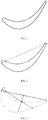
FIG. 1 is a schematic diagram of a blade profile measuring point of an aero-engine blade according to an embodiment of the present application; -
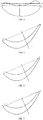
FIG. 2 is a schematic diagram when there are four intersection points of a secant and a blade profile according to an embodiment of the present invention; -
FIG. 3 is a schematic diagram when there are three intersection points of a secant and a blade profile according toy an embodiment of the present invention; -
FIG. 4 is a schematic diagram when there are two intersection points of a secant and a blade profile according to an embodiment of the present invention; -
FIG. 5 is a schematic diagram of a segmented blade profile according toy an embodiment of the present invention; -
FIG. 6 is a schematic diagram of a leading edge point set and a trailing edge point set obtained by a segmented blade profile according toy an embodiment of the present invention; -
FIG. 7 is a schematic diagram of a rotary secant according to an embodiment of the present invention; -
FIG. 8 is a schematic diagram of a first tangent point found by a rotary secant according to an embodiment of the present invention; and -
FIG. 9 is a schematic diagram of a second tangent point found by a rotary secant according to an embodiment of the present invention. - To further illustrate the objectives, technical solutions, and advantages of the present invention, the present invention will be further described below in detail with reference to the accompanying drawings and embodiments. It should be understood that the specific embodiments described herein are only used to explain the present invention and are not intended to limit the present invention. In addition, the technical features involved in the various embodiments of the present invention described below can be combined with each other as long as they do not constitute a conflict with each other.
- A method for determining and calculating a profile chord length of an aero-engine blade based on secant rotation iteration includes the following steps:
- (1) a connection line between two furthermost points in a blade profile measuring point set is taken as a secant, the secant is rotated or translated to intersect with a pressure surface, and thus a leading edge point set and a trailing edge point set are obtained; and
- (2) the secant is rotated in a range of the leading edge point set and the trailing edge point set to obtain tangent points of the secant and leading and trailing edges, and a distance between the two tangent points is calculated to obtain a chord length.
- The method may further include:
the chord length calculated in step (2) is compared with a standard chord length, wherein when a difference between the chord length and the standard chord length is less than a preset value, the aerodynamic performance and safety of the blade meet requirements. - Specifically, step (1) of the present application may include the following steps: (11) as shown in
FIG. 1 , blade profile measuring points of the aero-engine blade are collected by a three-coordinate detection measuring machine and a point laser displacement sensor to obtain a blade profile measuring point set, and a connecting line between two most distant points in the blade profile measuring point set is taken as a secant; and by selecting any two points pi(xi ,yi ) and pj(xj ,yj ) in the blade profile measuring point set, the distance
- (12) The secant is rotated or translated to intersect with the pressure surface at two points, and the coordinates (xi ,yi ) of any point pi in the blade profile measuring point set are substituted into the linear equation of the secant to obtain Si = (yb - ya )(xi - xa ) + (xa - xb )(yi - ya ), wherein (xa ,yb ) and (xb ,yb ) are two endpoints of the secant, and Si is a value obtained by substituting pi into the linear equation; Si is compared with a threshold δs, wherein the threshold


FIG. 2 , when the intersection points of the secant and the blade profile are A, C, D and B, the two middle points C and D are the intersection points of the secant and the pressure surface when the four intersection points are connected; as shown inFIG. 3 , when the intersection points of the secant and the blade profile are A, C and B, a straight line passing a midpoint E between the two points A and C is made, a straight line passing the midpoint E is obtained to intersect with the pressure surface at D, the C and D are connected to obtain a secant, the other two intersection points A' and B' of the secant and the blade profile are calculated, or the point C is fixed and the secant is rotated to obtain the intersection point D of the secant and the pressure surface, and the C and D are taken as the intersection points of the secant and the pressure surface; and as shown inFIG. 4 , when there are two intersection points of the secant and the blade profile, the secant is translated along a midperpendicular direction of the two points A and B until the secant is intersected with the blade profile at four points, wherein the points C and D are the intersection points of the secant and the pressure surface. - Firstly, a straight line T is made by passing a midpoint E(xe,ye) of the intersection points C(xc,yc) and D(xd,yd) of the secant L and the pressure surface and is perpendicular to the secant L, the linear equation is (yb - ya)(y - ye) + (xb - xa)(x - xe) = 0, then the intersection point of the straight line T and the blade profile is calculated, that is, any point pi(xI,yI) in the blade profile is substituted into the linear equation to obtain di = (yb - ya )(yi - ye ) + (xb - xa )(xi - xe ) so as to obtain two intersection points / and I', then the distance from the points I and I' to the secant L is calculated, as shown in
FIG. 5 , the closer intersection point is the intersection point I of the straight line T and the pressure surface. - (13) The blade profile is segmented by the secant and the intersection point of the straight line and the pressure surface to obtain the leading edge point set and the trailing edge point set.
- As shown in
FIG. 6 , the secant L divides the blade profile into two parts, the two parts and the point I can fall on the same side of the secant L and fall on the different sides of the secant L. Based on the above position relationship, the blade profile can be divided into two parts Psame = {pi (xi ,yi ) ∈ P|((yb - ya )(xi - xa ) + (xa - xb )(yi - ya ))· SI > 0} and Pvary = {pi (xi ,yi ) ∈ P|((yb - ya )(xi - xα ) + (xa - xb )(yi - ya ))· SI ≤ 0, wherein SI = (yb - ya)(xI - xa) + (xa - xb)(yI - ya). Then based on the position relationship between the point pi and the straight line T, the point set Pvary can be divided into a leading edge point set Pl = {pi (xi ,yi ) ∈ Pvary |(yb - ya)(yi - ye) + (xb - xa)(xi - xe ) < 0} and a trailing edge point set Pt = {pi (x i,yi) ∈ Pvary |(yb - ya )(yi - ye ) + (xb - xa )(xi - xe) > 0}. - Step (2) may include:
- (21) the leading edge point set is sorted according to a distance between points in the leading edge point set and the straight line, and the trailing edge point set is sorted according to a distance between points in the trailing edge point set and the straight line;
- (22) fixing an endpoint of the secant, and sequentially rotating the secant according to a sorting result in the trailing edge point set to obtain a tangent point of the secant and the trailing edge; and
- (23) fixing the tangent point of the secant and the trailing edge, sequentially rotating the secant according to a sorting result in the leading edge point set to obtain a tangent point of the secant and the leading edge, and calculating a distance between the two tangent points to obtain a chord length.
- Alternativelystep (2) may include:
- (21) the leading edge point set is sorted according to a distance between points in the leading edge point set and the straight line, and the trailing edge point set is sorted according to a distance between points in the trailing edge point set and the straight line;
- (22) fixing an endpoint of the secant, and sequentially rotating the secant according to a sorting result in the leading edge point set to obtain a tangent point of the secant and the leading edge; and
- (23) the tangent point of the secant and the leading edge is fixed, the secant is sequentially rotated according to a sorting result in the trailing edge point set to obtain a tangent point of the secant and the trailing edge, and a distance between the two tangent points is calculated to obtain a chord length.
- The present invention takes one of the above as an example for detailed description.
- Firstly, a distance


- As shown in
FIG. 7 , the point A is firstly fixed, the point A and the point Bi(xbI ,ybI ) are sequentially connected to obtain a new secant LBi, the linear equation of the secantLBi is (ybi - ya )(x - xa) + (xa - xbi )(y - ya) = 0, whether a midpoint pi of the
i - ya)(xi - xa) + (xa - xbi )(yi - ya )) · ((ybi - ya )(xi - xa ) + (xa - xbi )(yi - ya )) > 0 is true or not is judged, if the point Bi is not true, a new secant L Bi+1 is continuously constructed, otherwise, iteration is stopped to obtain a secant LBi , such that all points in
FIG. 8 . - As shown in
FIG. 9 , firstly, a tangent point Te of the trailing edge is fixed, a point Te and a point Ai(xai ,yai ) are sequentially connected to obtain a new secant LAi , the linear equation of the secant LAi is (yte - yai )(x - xai ) + (xai - xte )(y - yai ) = 0, whether a midpoint pi falls on one side of LAi with the point I is determined, that is, whether ((yte - yai )(xi - xai ) + (xai - xte )(yi - yai )) · ((yte - yai )(xi - xai ) + (xai - xte)(yi - yai )) > 0 is true or not is determined, if the point Ai is not true, a new secant LAI is continuously constructed, otherwise, iteration is stopped to obtain a secant LAi , such that all the points in

- The method of the present invention is suitable for calculating the profile chord length of various types of aero-engine blades, that is, calculating the profile chord length of the aero-engine blade based on secant rotation iteration.
- It is clear for those skilled in the art that the above are only preferred embodiments of the present invention, and these are not intended to limit the present invention. Any modifications, equivalent substitutions and improvements and the like made within the spirit and principles of the present invention should fall within the protection scope of the present invention.
Claims (10)
- A method for determining and calculating a profile chord length of an aero-engine blade based on secant rotation iteration, characterized by comprising the following steps:(1) taking a connection line between two most distant points in a blade profile measuring point set as a secant, rotating or translating the secant to enable the secant to intersect with a pressure surface, thus obtaining a leading edge point set and a trailing edge point set; and(2) rotating the secant in a range of the leading edge point set and the trailing edge point set to obtain tangent points of the secant and leading and trailing edges, and calculating a distance between the two tangent points to obtain a chord length.
- The method for determining and calculating the profile chord length of the aero-engine blade based on secant rotation iteration according to claim 1, characterized by further comprising:
comparing the chord length calculated in the step (2) with a standard chord length, wherein when an error between the chord length and the standard chord length is less than a preset value, the aerodynamic performance and safety of the blade meet requirements. - The method for determining and calculating the profile chord length of the aero-engine blade based on secant rotation iteration according to claim 1 or 2, characterized in that the step (1) comprises:(11) collecting blade profile measuring points of the aero-engine blade to form a blade profile measuring point set, and taking a connecting line between two most distant points in the blade profile measuring point set as a secant;(12) rotating or translating the secant to enable the secant to intersect with a pressure surface at two points, and making a straight line perpendicular to the secant by using a midpoint of a connecting line of the two points to obtain an intersection point of the straight line and the pressure surface; and(13) segmenting a blade profile by the secant and the intersection point of the straight line and the pressure surface to obtain a leading edge point set and a trailing edge point set.
- The method for determining and calculating the profile chord length of the aero-engine blade based on secant rotation iteration according to claim 1 or 2, characterized in that the step (1) of rotating or translating the secant to enable the secant to intersect with the pressure surface, is specifically implemented as follows:
substituting coordinates (xi ,yi ) of any point pi in the blade profile measuring point set into a linear equation of the secant to obtain Si = (yb - ya )(xi - xa ) + (xa - xb )(yi - ya ), wherein (xa ,yb ) and (xb,yb ) are two endpoints of the secant, and Si is a value obtained by substituting pi into the linear equation; comparing Si with a threshold δs, and when Si is less than the threshold δs, takingpi as the intersection point of the blade profile; intersection points of the secant and the blade profile being 2 or 3 or 4; when there are 4 intersection points of the secant and the blade profile, two middle points when the four intersection points are connected are the intersection points of the secant and the pressure surface; when there are 3 intersection points of the secant and the blade profile, rotating the secant to obtain the intersection point of the secant and the pressure surface; and when there are 2 intersection points of the secant and the blade profile, translating the secant to obtain the intersection point of the secant and the pressure surface. - The method for determining and calculating the profile chord length of the aero-engine blade based on secant rotation iteration according to claim 4, characterized in that the threshold

- The method for determining and calculating the profile chord length of the aero-engine blade based on secant rotation iteration according to claim 3 or 5, characterized in that the step (2) comprises:(21) sorting the leading edge point set according to a distance between points in the leading edge point set and the straight line, and sorting the trailing edge point set according to a distance between points in the trailing edge point set and the straight line;(22) fixing an endpoint of the secant, and sequentially rotating the secant according to a sorting result in the trailing edge point set to obtain a tangent point of the secant and the trailing edge; and(23) fixing the tangent point of the secant and the trailing edge, sequentially rotating the secant according to a sorting result in the leading edge point set to obtain a tangent point of the secant and the leading edge, and calculating a distance between the two tangent points to obtain a chord length.
- The method for determining and calculating the profile chord length of the aero-engine blade based on secant rotation iteration according to claim 3 or 5, characterized in that the step (2) comprises:(21) sorting the leading edge point set according to a distance between points in the leading edge point set and the straight line, and sorting the trailing edge point set according to a distance between points in the trailing edge point set and the straight line;(22) fixing an endpoint of the secant, and sequentially rotating the secant according to a sorting result in the leading edge point set to obtain a tangent point of the secant and the leading edge; and(23) fixing the tangent point of the secant and the leading edge, sequentially rotating the secant according to a sorting result in the trailing edge point set to obtain a tangent point of the secant and the trailing edge, and calculating a distance between the two tangent points to obtain a chord length.
- A system for determining and calculating a profile chord length of an aero-engine blade based on secant rotation iteration, characterized by comprising:
a point set segmentation module, configured to take a connection line between two most distant points in a blade profile measuring point set as a secant, and rotate or translate the secant to enable the secant to intersect with a pressure surface so as to obtain a leading edge point set and a trailing edge point set; and
a secant rotation module, configured to rotate the secant in a range of the leading edge point set and the trailing edge point set to obtain tangent points of the secant and a leading edge and a trailing edge, and calculate a distance between the two tangent points to obtain a chord length. - The system for determining and calculating the profile chord length of the aero-engine blade based on secant rotation iteration according to claim 8, characterized by further comprising:
a blade performance evaluation module, configured to compare the chord length calculated by the secant rotation module with a standard chord length, wherein when an error between the chord length and the standard chord length is less than a preset value, the aerodynamic performance and safety of the blade meet requirements. - The system for determining and calculating the profile chord length of the aero-engine blade based on secant rotation iteration according to claim 8 or 9, characterized in that the point set segmentation module comprises:a first module, configured to collect blade profile measuring points of the aero-engine blade to form a blade profile measuring point set, and take a connecting line between two most distant points in the blade profile measuring point set as a secant;a second module, configured to rotate or translate the secant to enable the secant to intersect with a pressure surface at two points, and use a midpoint of a connecting line of the two points to make a straight line perpendicular to the secant to obtain an intersection point of the straight line and the pressure surface; anda third module, configured to segment a blade profile by the secant and the intersection point of the straight line and the pressure surface to obtain a leading edge point set and a trailing edge point set.
Applications Claiming Priority (2)
| Application Number | Priority Date | Filing Date | Title |
|---|---|---|---|
| CN202010233826.8A CN111382482B (en) | 2020-03-29 | 2020-03-29 | Method and system for detecting blade profile chord length of aviation blade based on secant rotation iteration |
| PCT/CN2020/095986 WO2021196407A1 (en) | 2020-03-29 | 2020-06-13 | Aviation blade profile chord length measurement method and system based on secant rotation iteration |
Publications (3)
| Publication Number | Publication Date |
|---|---|
| EP3913520A1 true EP3913520A1 (en) | 2021-11-24 |
| EP3913520A4 EP3913520A4 (en) | 2022-06-29 |
| EP3913520B1 EP3913520B1 (en) | 2025-04-16 |
Family
ID=71220062
Family Applications (1)
| Application Number | Title | Priority Date | Filing Date |
|---|---|---|---|
| EP20904296.9A Active EP3913520B1 (en) | 2020-03-29 | 2020-06-13 | Aviation blade profile chord length measurement method and system based on secant rotation iteration |
Country Status (3)
| Country | Link |
|---|---|
| EP (1) | EP3913520B1 (en) |
| CN (1) | CN111382482B (en) |
| WO (1) | WO2021196407A1 (en) |
Families Citing this family (6)
| Publication number | Priority date | Publication date | Assignee | Title |
|---|---|---|---|---|
| CN114357655B (en) * | 2022-01-05 | 2025-05-30 | 中国航空制造技术研究院 | A method and device for identifying geometric features of blade profiles |
| CN114492230B (en) * | 2022-01-06 | 2022-08-09 | 中国空气动力研究与发展中心计算空气动力研究所 | Method for obtaining high-altitude aerodynamic force curve of aircraft |
| CN115423053B (en) * | 2022-11-07 | 2023-04-07 | 中国空气动力研究与发展中心计算空气动力研究所 | Method and related equipment for classifying unstructured flow field data suitable for airfoil section |
| CN116202395B (en) * | 2023-02-15 | 2026-05-08 | 重庆三耐科技有限责任公司 | Design method of conformal self-positioning blade chord length gauge |
| CN117408025B (en) * | 2023-09-25 | 2025-05-09 | 中国航发沈阳黎明航空发动机有限责任公司 | Calculation method for chord length removal amount of blade profile vibration finishing |
| CN120116028A (en) * | 2025-03-21 | 2025-06-10 | 安徽应流航源动力科技有限公司 | A nozzle ring blade patch grinding detection method |
Family Cites Families (12)
| Publication number | Priority date | Publication date | Assignee | Title |
|---|---|---|---|---|
| FR2889308B1 (en) * | 2005-07-28 | 2007-10-05 | Snecma | CONTROL OF TURBOMACHINE AUBES |
| US7497663B2 (en) * | 2006-10-26 | 2009-03-03 | General Electric Company | Rotor blade profile optimization |
| DE102011102286A1 (en) * | 2011-05-23 | 2012-11-29 | Lufthansa Technik Ag | Method for producing aerodynamically optimized contour of leading edges of gas turbine blade, involves digitization of leading edge of gas turbine blade and detecting trailing edge of gas turbine blade |
| CN102735204B (en) * | 2012-06-07 | 2014-07-23 | 华中科技大学 | Chord-line-based aviation thin-wall blade machining torsion degree error measurement method |
| CN103093091B (en) * | 2013-01-11 | 2015-09-16 | 西北工业大学 | Based on the aerial blade circular arc front and rear edge method for reconstructing of control errors |
| FR3032494B1 (en) * | 2015-02-06 | 2018-05-25 | Safran Aircraft Engines | AUBE DE SOUFFLANTE |
| CN104697462B (en) * | 2015-03-24 | 2017-07-28 | 武汉克诺德智能科技有限公司 | A kind of aerial blade surface-type feature parameter extracting method based on axis |
| US10400744B2 (en) * | 2016-04-28 | 2019-09-03 | General Electric Company | Wind turbine blade with noise reducing micro boundary layer energizers |
| CN107357959B (en) * | 2017-06-14 | 2020-11-10 | 西安交通大学 | High-precision blade section characteristic parameter extraction method |
| CN107806836A (en) * | 2017-09-28 | 2018-03-16 | 中国航发动力股份有限公司 | A detection method of precision forging blade surface based on five-axis linkage point light source |
| CN110781573B (en) * | 2019-08-13 | 2023-11-10 | 中国航发贵阳发动机设计研究所 | Mapping design method for aero-engine rotor blade |
| CN110489939A (en) * | 2019-10-21 | 2019-11-22 | 辽宁壮龙无人机科技有限公司 | An optimization method, optimization device and readable storage medium for propeller design |
-
2020
- 2020-03-29 CN CN202010233826.8A patent/CN111382482B/en active Active
- 2020-06-13 EP EP20904296.9A patent/EP3913520B1/en active Active
- 2020-06-13 WO PCT/CN2020/095986 patent/WO2021196407A1/en not_active Ceased
Also Published As
| Publication number | Publication date |
|---|---|
| CN111382482A (en) | 2020-07-07 |
| CN111382482B (en) | 2022-02-15 |
| EP3913520A4 (en) | 2022-06-29 |
| WO2021196407A1 (en) | 2021-10-07 |
| EP3913520B1 (en) | 2025-04-16 |
Similar Documents
| Publication | Publication Date | Title |
|---|---|---|
| EP3913520B1 (en) | Aviation blade profile chord length measurement method and system based on secant rotation iteration | |
| US4908782A (en) | Airfoil inspection method | |
| US20220122317A1 (en) | Method for measuring a seam on aircraft skin based on large-scale point cloud | |
| US10393788B2 (en) | Apparatus and method for diagnosing state of power cable and measuring remaining life thereof using VLF TD measurement data | |
| CN102735204B (en) | Chord-line-based aviation thin-wall blade machining torsion degree error measurement method | |
| CN114543731B (en) | Blade detection method and device | |
| CN104316016A (en) | Longitudinal measurement method for blisk complex curved surface blade | |
| CN110329423A (en) | A kind of accuracy control method of hull Quick carrying | |
| US20090324093A1 (en) | Method for comparing sectioned geometric data representations for selected objects | |
| CN112013788A (en) | Method for calibrating rotation center based on curve characteristics of local leading edge of blade | |
| CN105389648A (en) | Distinguishing method for steady-state operating condition of atmospheric and vacuum distillation device | |
| CN111797545B (en) | Wind turbine generator yaw reduction coefficient calculation method based on measured data | |
| CN115358026A (en) | A five-hole probe data processing method based on multiple linear regression and surface fitting | |
| CN113204871A (en) | Aviation blade air film hole identification method, device and system | |
| CN118501605A (en) | A quality inspection system for nanosilver transparent conductive film based on machine vision | |
| CN119348785A (en) | A fast reconstruction method of hull segment outer plate based on feature splicing | |
| CN110400066A (en) | A Statistical Analysis Device for Machining Errors | |
| CN115078377A (en) | Automatic bridge damage evaluation system and method based on point cloud fitting | |
| CN118424619B (en) | Corrugated guardrail stiffness detection method and system based on microwave radar and spectral clustering | |
| CN105571558A (en) | Compressor blade spanwise waviness quantitative determination method | |
| CN116164695B (en) | Turbine guide and exhaust area measurement method thereof | |
| CN119005705A (en) | Multi-source data fusion tunnel gushing water comprehensive forecasting method and device | |
| CN105654521A (en) | Impeller blade rim point obtaining method | |
| CN115808148A (en) | Digitized detection method for blade waviness of aircraft engine | |
| CN116499376A (en) | Object thickness measuring method based on 3D point cloud |
Legal Events
| Date | Code | Title | Description |
|---|---|---|---|
| STAA | Information on the status of an ep patent application or granted ep patent |
Free format text: STATUS: UNKNOWN |
|
| STAA | Information on the status of an ep patent application or granted ep patent |
Free format text: STATUS: THE INTERNATIONAL PUBLICATION HAS BEEN MADE |
|
| PUAI | Public reference made under article 153(3) epc to a published international application that has entered the european phase |
Free format text: ORIGINAL CODE: 0009012 |
|
| STAA | Information on the status of an ep patent application or granted ep patent |
Free format text: STATUS: REQUEST FOR EXAMINATION WAS MADE |
|
| 17P | Request for examination filed |
Effective date: 20210702 |
|
| AK | Designated contracting states |
Kind code of ref document: A1 Designated state(s): AL AT BE BG CH CY CZ DE DK EE ES FI FR GB GR HR HU IE IS IT LI LT LU LV MC MK MT NL NO PL PT RO RS SE SI SK SM TR |
|
| RIN1 | Information on inventor provided before grant (corrected) |
Inventor name: DING, HAN Inventor name: FENG, SHENG Inventor name: JIANG, CHENG Inventor name: JIN, FUQUAN Inventor name: LI, WENLONG |
|
| RIN1 | Information on inventor provided before grant (corrected) |
Inventor name: DING, HAN Inventor name: FENG, SHENG Inventor name: JIN, FUQUAN Inventor name: JIANG, CHENG Inventor name: LI, WENLONG |
|
| A4 | Supplementary search report drawn up and despatched |
Effective date: 20220531 |
|
| RIC1 | Information provided on ipc code assigned before grant |
Ipc: F01D 5/14 20060101ALI20220524BHEP Ipc: G06F 30/17 20200101AFI20220524BHEP |
|
| DAV | Request for validation of the european patent (deleted) | ||
| DAX | Request for extension of the european patent (deleted) | ||
| STAA | Information on the status of an ep patent application or granted ep patent |
Free format text: STATUS: EXAMINATION IS IN PROGRESS |
|
| 17Q | First examination report despatched |
Effective date: 20241114 |
|
| RIN1 | Information on inventor provided before grant (corrected) |
Inventor name: DING, HAN Inventor name: FEN, SHENG Inventor name: JIN, FUQUAN Inventor name: JIANG, CHENG Inventor name: XU, WEI Inventor name: LI, WENLONG |
|
| GRAP | Despatch of communication of intention to grant a patent |
Free format text: ORIGINAL CODE: EPIDOSNIGR1 |
|
| STAA | Information on the status of an ep patent application or granted ep patent |
Free format text: STATUS: GRANT OF PATENT IS INTENDED |
|
| GRAS | Grant fee paid |
Free format text: ORIGINAL CODE: EPIDOSNIGR3 |
|
| GRAA | (expected) grant |
Free format text: ORIGINAL CODE: 0009210 |
|
| STAA | Information on the status of an ep patent application or granted ep patent |
Free format text: STATUS: THE PATENT HAS BEEN GRANTED |
|
| INTG | Intention to grant announced |
Effective date: 20250214 |
|
| AK | Designated contracting states |
Kind code of ref document: B1 Designated state(s): AL AT BE BG CH CY CZ DE DK EE ES FI FR GB GR HR HU IE IS IT LI LT LU LV MC MK MT NL NO PL PT RO RS SE SI SK SM TR |
|
| REG | Reference to a national code |
Ref country code: GB Ref legal event code: FG4D |
|
| REG | Reference to a national code |
Ref country code: CH Ref legal event code: EP |
|
| REG | Reference to a national code |
Ref country code: IE Ref legal event code: FG4D |
|
| REG | Reference to a national code |
Ref country code: DE Ref legal event code: R096 Ref document number: 602020049738 Country of ref document: DE |
|
| PGFP | Annual fee paid to national office [announced via postgrant information from national office to epo] |
Ref country code: GB Payment date: 20250620 Year of fee payment: 6 |
|
| PGFP | Annual fee paid to national office [announced via postgrant information from national office to epo] |
Ref country code: FR Payment date: 20250626 Year of fee payment: 6 |
|
| REG | Reference to a national code |
Ref country code: NL Ref legal event code: MP Effective date: 20250416 |
|
| PG25 | Lapsed in a contracting state [announced via postgrant information from national office to epo] |
Ref country code: NL Free format text: LAPSE BECAUSE OF FAILURE TO SUBMIT A TRANSLATION OF THE DESCRIPTION OR TO PAY THE FEE WITHIN THE PRESCRIBED TIME-LIMIT Effective date: 20250416 |
|
| REG | Reference to a national code |
Ref country code: AT Ref legal event code: MK05 Ref document number: 1786247 Country of ref document: AT Kind code of ref document: T Effective date: 20250416 |
|
| PG25 | Lapsed in a contracting state [announced via postgrant information from national office to epo] |
Ref country code: FI Free format text: LAPSE BECAUSE OF FAILURE TO SUBMIT A TRANSLATION OF THE DESCRIPTION OR TO PAY THE FEE WITHIN THE PRESCRIBED TIME-LIMIT Effective date: 20250416 Ref country code: ES Free format text: LAPSE BECAUSE OF FAILURE TO SUBMIT A TRANSLATION OF THE DESCRIPTION OR TO PAY THE FEE WITHIN THE PRESCRIBED TIME-LIMIT Effective date: 20250416 Ref country code: PT Free format text: LAPSE BECAUSE OF FAILURE TO SUBMIT A TRANSLATION OF THE DESCRIPTION OR TO PAY THE FEE WITHIN THE PRESCRIBED TIME-LIMIT Effective date: 20250818 |
|
| PGFP | Annual fee paid to national office [announced via postgrant information from national office to epo] |
Ref country code: DE Payment date: 20250627 Year of fee payment: 6 |
|
| REG | Reference to a national code |
Ref country code: LT Ref legal event code: MG9D |
|
| PG25 | Lapsed in a contracting state [announced via postgrant information from national office to epo] |
Ref country code: NO Free format text: LAPSE BECAUSE OF FAILURE TO SUBMIT A TRANSLATION OF THE DESCRIPTION OR TO PAY THE FEE WITHIN THE PRESCRIBED TIME-LIMIT Effective date: 20250716 Ref country code: GR Free format text: LAPSE BECAUSE OF FAILURE TO SUBMIT A TRANSLATION OF THE DESCRIPTION OR TO PAY THE FEE WITHIN THE PRESCRIBED TIME-LIMIT Effective date: 20250717 |
|
| PG25 | Lapsed in a contracting state [announced via postgrant information from national office to epo] |
Ref country code: PL Free format text: LAPSE BECAUSE OF FAILURE TO SUBMIT A TRANSLATION OF THE DESCRIPTION OR TO PAY THE FEE WITHIN THE PRESCRIBED TIME-LIMIT Effective date: 20250416 |
|
| PG25 | Lapsed in a contracting state [announced via postgrant information from national office to epo] |
Ref country code: BG Free format text: LAPSE BECAUSE OF FAILURE TO SUBMIT A TRANSLATION OF THE DESCRIPTION OR TO PAY THE FEE WITHIN THE PRESCRIBED TIME-LIMIT Effective date: 20250416 |
|
| PG25 | Lapsed in a contracting state [announced via postgrant information from national office to epo] |
Ref country code: HR Free format text: LAPSE BECAUSE OF FAILURE TO SUBMIT A TRANSLATION OF THE DESCRIPTION OR TO PAY THE FEE WITHIN THE PRESCRIBED TIME-LIMIT Effective date: 20250416 |
|
| PG25 | Lapsed in a contracting state [announced via postgrant information from national office to epo] |
Ref country code: AT Free format text: LAPSE BECAUSE OF FAILURE TO SUBMIT A TRANSLATION OF THE DESCRIPTION OR TO PAY THE FEE WITHIN THE PRESCRIBED TIME-LIMIT Effective date: 20250416 |
|
| PG25 | Lapsed in a contracting state [announced via postgrant information from national office to epo] |
Ref country code: RS Free format text: LAPSE BECAUSE OF FAILURE TO SUBMIT A TRANSLATION OF THE DESCRIPTION OR TO PAY THE FEE WITHIN THE PRESCRIBED TIME-LIMIT Effective date: 20250716 |
|
| PG25 | Lapsed in a contracting state [announced via postgrant information from national office to epo] |
Ref country code: IS Free format text: LAPSE BECAUSE OF FAILURE TO SUBMIT A TRANSLATION OF THE DESCRIPTION OR TO PAY THE FEE WITHIN THE PRESCRIBED TIME-LIMIT Effective date: 20250816 |
|
| PG25 | Lapsed in a contracting state [announced via postgrant information from national office to epo] |
Ref country code: LV Free format text: LAPSE BECAUSE OF FAILURE TO SUBMIT A TRANSLATION OF THE DESCRIPTION OR TO PAY THE FEE WITHIN THE PRESCRIBED TIME-LIMIT Effective date: 20250416 |
|
| PG25 | Lapsed in a contracting state [announced via postgrant information from national office to epo] |
Ref country code: DK Free format text: LAPSE BECAUSE OF FAILURE TO SUBMIT A TRANSLATION OF THE DESCRIPTION OR TO PAY THE FEE WITHIN THE PRESCRIBED TIME-LIMIT Effective date: 20250416 Ref country code: SM Free format text: LAPSE BECAUSE OF FAILURE TO SUBMIT A TRANSLATION OF THE DESCRIPTION OR TO PAY THE FEE WITHIN THE PRESCRIBED TIME-LIMIT Effective date: 20250416 |
|
| REG | Reference to a national code |
Ref country code: DE Ref legal event code: R097 Ref document number: 602020049738 Country of ref document: DE |
|
| PG25 | Lapsed in a contracting state [announced via postgrant information from national office to epo] |
Ref country code: CZ Free format text: LAPSE BECAUSE OF FAILURE TO SUBMIT A TRANSLATION OF THE DESCRIPTION OR TO PAY THE FEE WITHIN THE PRESCRIBED TIME-LIMIT Effective date: 20250416 |
|
| PG25 | Lapsed in a contracting state [announced via postgrant information from national office to epo] |
Ref country code: EE Free format text: LAPSE BECAUSE OF FAILURE TO SUBMIT A TRANSLATION OF THE DESCRIPTION OR TO PAY THE FEE WITHIN THE PRESCRIBED TIME-LIMIT Effective date: 20250416 |
|
| PG25 | Lapsed in a contracting state [announced via postgrant information from national office to epo] |
Ref country code: SK Free format text: LAPSE BECAUSE OF FAILURE TO SUBMIT A TRANSLATION OF THE DESCRIPTION OR TO PAY THE FEE WITHIN THE PRESCRIBED TIME-LIMIT Effective date: 20250416 |
|
| REG | Reference to a national code |
Ref country code: CH Ref legal event code: H13 Free format text: ST27 STATUS EVENT CODE: U-0-0-H10-H13 (AS PROVIDED BY THE NATIONAL OFFICE) Effective date: 20260127 |
|
| PG25 | Lapsed in a contracting state [announced via postgrant information from national office to epo] |
Ref country code: IT Free format text: LAPSE BECAUSE OF FAILURE TO SUBMIT A TRANSLATION OF THE DESCRIPTION OR TO PAY THE FEE WITHIN THE PRESCRIBED TIME-LIMIT Effective date: 20250416 |
|
| PG25 | Lapsed in a contracting state [announced via postgrant information from national office to epo] |
Ref country code: MC Free format text: LAPSE BECAUSE OF FAILURE TO SUBMIT A TRANSLATION OF THE DESCRIPTION OR TO PAY THE FEE WITHIN THE PRESCRIBED TIME-LIMIT Effective date: 20250416 |
|
| PG25 | Lapsed in a contracting state [announced via postgrant information from national office to epo] |
Ref country code: LU Free format text: LAPSE BECAUSE OF NON-PAYMENT OF DUE FEES Effective date: 20250613 |
|
| PLBE | No opposition filed within time limit |
Free format text: ORIGINAL CODE: 0009261 |
|
| STAA | Information on the status of an ep patent application or granted ep patent |
Free format text: STATUS: NO OPPOSITION FILED WITHIN TIME LIMIT |
|
| REG | Reference to a national code |
Ref country code: CH Ref legal event code: L10 Free format text: ST27 STATUS EVENT CODE: U-0-0-L10-L00 (AS PROVIDED BY THE NATIONAL OFFICE) Effective date: 20260225 |
|
| REG | Reference to a national code |
Ref country code: BE Ref legal event code: MM Effective date: 20250630 |
|
| PG25 | Lapsed in a contracting state [announced via postgrant information from national office to epo] |
Ref country code: RO Free format text: LAPSE BECAUSE OF FAILURE TO SUBMIT A TRANSLATION OF THE DESCRIPTION OR TO PAY THE FEE WITHIN THE PRESCRIBED TIME-LIMIT Effective date: 20250416 |
|
| 26N | No opposition filed |
Effective date: 20260119 |
|
| PG25 | Lapsed in a contracting state [announced via postgrant information from national office to epo] |
Ref country code: IE Free format text: LAPSE BECAUSE OF NON-PAYMENT OF DUE FEES Effective date: 20250613 |
|
| PG25 | Lapsed in a contracting state [announced via postgrant information from national office to epo] |
Ref country code: BE Free format text: LAPSE BECAUSE OF NON-PAYMENT OF DUE FEES Effective date: 20250630 |
|
| PG25 | Lapsed in a contracting state [announced via postgrant information from national office to epo] |
Ref country code: CH Free format text: LAPSE BECAUSE OF NON-PAYMENT OF DUE FEES Effective date: 20250630 |