EP3913412A2 - Optical fiber with dual trench design - Google Patents
Optical fiber with dual trench design Download PDFInfo
- Publication number
- EP3913412A2 EP3913412A2 EP21172798.7A EP21172798A EP3913412A2 EP 3913412 A2 EP3913412 A2 EP 3913412A2 EP 21172798 A EP21172798 A EP 21172798A EP 3913412 A2 EP3913412 A2 EP 3913412A2
- Authority
- EP
- European Patent Office
- Prior art keywords
- depressed
- index
- microns
- cladding region
- less
- Prior art date
- Legal status (The legal status is an assumption and is not a legal conclusion. Google has not performed a legal analysis and makes no representation as to the accuracy of the status listed.)
- Pending
Links
- 239000013307 optical fiber Substances 0.000 title claims abstract description 142
- 238000013461 design Methods 0.000 title description 22
- 230000009977 dual effect Effects 0.000 title description 18
- 238000005253 cladding Methods 0.000 claims description 404
- 239000006185 dispersion Substances 0.000 claims description 64
- 230000003247 decreasing effect Effects 0.000 claims description 2
- 238000000576 coating method Methods 0.000 description 35
- 239000011248 coating agent Substances 0.000 description 34
- VYPSYNLAJGMNEJ-UHFFFAOYSA-N Silicium dioxide Chemical compound O=[Si]=O VYPSYNLAJGMNEJ-UHFFFAOYSA-N 0.000 description 32
- 230000000994 depressogenic effect Effects 0.000 description 31
- 239000000835 fiber Substances 0.000 description 25
- 239000004071 soot Substances 0.000 description 16
- 239000003365 glass fiber Substances 0.000 description 14
- 230000000052 comparative effect Effects 0.000 description 12
- YCKRFDGAMUMZLT-UHFFFAOYSA-N Fluorine atom Chemical compound [F] YCKRFDGAMUMZLT-UHFFFAOYSA-N 0.000 description 11
- 229910052731 fluorine Inorganic materials 0.000 description 11
- 239000011737 fluorine Substances 0.000 description 11
- 239000011521 glass Substances 0.000 description 11
- YBMRDBCBODYGJE-UHFFFAOYSA-N germanium dioxide Chemical compound O=[Ge]=O YBMRDBCBODYGJE-UHFFFAOYSA-N 0.000 description 8
- 238000000034 method Methods 0.000 description 8
- 230000003287 optical effect Effects 0.000 description 7
- 238000007596 consolidation process Methods 0.000 description 6
- 239000000377 silicon dioxide Substances 0.000 description 6
- 238000012360 testing method Methods 0.000 description 6
- 230000007704 transition Effects 0.000 description 6
- 239000000463 material Substances 0.000 description 5
- -1 GeO2) Chemical compound 0.000 description 4
- 238000005452 bending Methods 0.000 description 4
- ZOXJGFHDIHLPTG-UHFFFAOYSA-N Boron Chemical compound [B] ZOXJGFHDIHLPTG-UHFFFAOYSA-N 0.000 description 3
- ZAMOUSCENKQFHK-UHFFFAOYSA-N Chlorine atom Chemical compound [Cl] ZAMOUSCENKQFHK-UHFFFAOYSA-N 0.000 description 3
- 229910052796 boron Inorganic materials 0.000 description 3
- 239000003795 chemical substances by application Substances 0.000 description 3
- 229910052801 chlorine Inorganic materials 0.000 description 3
- 239000000460 chlorine Substances 0.000 description 3
- 230000018044 dehydration Effects 0.000 description 3
- 238000006297 dehydration reaction Methods 0.000 description 3
- 239000002019 doping agent Substances 0.000 description 3
- 229910052732 germanium Inorganic materials 0.000 description 3
- GNPVGFCGXDBREM-UHFFFAOYSA-N germanium atom Chemical compound [Ge] GNPVGFCGXDBREM-UHFFFAOYSA-N 0.000 description 3
- 239000011159 matrix material Substances 0.000 description 3
- 238000005259 measurement Methods 0.000 description 3
- 238000000691 measurement method Methods 0.000 description 3
- 239000000203 mixture Substances 0.000 description 3
- 230000004048 modification Effects 0.000 description 3
- 238000012986 modification Methods 0.000 description 3
- 235000012239 silicon dioxide Nutrition 0.000 description 3
- 238000005728 strengthening Methods 0.000 description 3
- 239000011800 void material Substances 0.000 description 3
- 230000002411 adverse Effects 0.000 description 2
- 239000003513 alkali Substances 0.000 description 2
- 230000008901 benefit Effects 0.000 description 2
- 230000008859 change Effects 0.000 description 2
- 238000007796 conventional method Methods 0.000 description 2
- 230000007423 decrease Effects 0.000 description 2
- 230000005684 electric field Effects 0.000 description 2
- 239000011152 fibreglass Substances 0.000 description 2
- 239000000976 ink Substances 0.000 description 2
- 239000000049 pigment Substances 0.000 description 2
- 230000008569 process Effects 0.000 description 2
- 238000012545 processing Methods 0.000 description 2
- 230000035945 sensitivity Effects 0.000 description 2
- 238000010998 test method Methods 0.000 description 2
- NIXOWILDQLNWCW-UHFFFAOYSA-M Acrylate Chemical compound [O-]C(=O)C=C NIXOWILDQLNWCW-UHFFFAOYSA-M 0.000 description 1
- KOPBYBDAPCDYFK-UHFFFAOYSA-N Cs2O Inorganic materials [O-2].[Cs+].[Cs+] KOPBYBDAPCDYFK-UHFFFAOYSA-N 0.000 description 1
- FUJCRWPEOMXPAD-UHFFFAOYSA-N Li2O Inorganic materials [Li+].[Li+].[O-2] FUJCRWPEOMXPAD-UHFFFAOYSA-N 0.000 description 1
- KKCBUQHMOMHUOY-UHFFFAOYSA-N Na2O Inorganic materials [O-2].[Na+].[Na+] KKCBUQHMOMHUOY-UHFFFAOYSA-N 0.000 description 1
- OAICVXFJPJFONN-UHFFFAOYSA-N Phosphorus Chemical compound [P] OAICVXFJPJFONN-UHFFFAOYSA-N 0.000 description 1
- 229910000831 Steel Inorganic materials 0.000 description 1
- 230000006978 adaptation Effects 0.000 description 1
- 229910000272 alkali metal oxide Inorganic materials 0.000 description 1
- 229910052782 aluminium Inorganic materials 0.000 description 1
- XAGFODPZIPBFFR-UHFFFAOYSA-N aluminium Chemical compound [Al] XAGFODPZIPBFFR-UHFFFAOYSA-N 0.000 description 1
- PNEYBMLMFCGWSK-UHFFFAOYSA-N aluminium oxide Inorganic materials [O-2].[O-2].[O-2].[Al+3].[Al+3] PNEYBMLMFCGWSK-UHFFFAOYSA-N 0.000 description 1
- 230000004888 barrier function Effects 0.000 description 1
- 230000009286 beneficial effect Effects 0.000 description 1
- 239000003086 colorant Substances 0.000 description 1
- 230000006835 compression Effects 0.000 description 1
- 238000007906 compression Methods 0.000 description 1
- 238000010276 construction Methods 0.000 description 1
- 229910052593 corundum Inorganic materials 0.000 description 1
- 230000008021 deposition Effects 0.000 description 1
- AKUNKIJLSDQFLS-UHFFFAOYSA-M dicesium;hydroxide Chemical compound [OH-].[Cs+].[Cs+] AKUNKIJLSDQFLS-UHFFFAOYSA-M 0.000 description 1
- 238000009792 diffusion process Methods 0.000 description 1
- XUCJHNOBJLKZNU-UHFFFAOYSA-M dilithium;hydroxide Chemical compound [Li+].[Li+].[OH-] XUCJHNOBJLKZNU-UHFFFAOYSA-M 0.000 description 1
- 238000009826 distribution Methods 0.000 description 1
- 230000000694 effects Effects 0.000 description 1
- 238000007689 inspection Methods 0.000 description 1
- 238000009434 installation Methods 0.000 description 1
- 238000004519 manufacturing process Methods 0.000 description 1
- 229910052751 metal Inorganic materials 0.000 description 1
- 239000002184 metal Substances 0.000 description 1
- 239000011574 phosphorus Substances 0.000 description 1
- 229910052698 phosphorus Inorganic materials 0.000 description 1
- 229920000642 polymer Polymers 0.000 description 1
- 239000002861 polymer material Substances 0.000 description 1
- NOTVAPJNGZMVSD-UHFFFAOYSA-N potassium monoxide Inorganic materials [K]O[K] NOTVAPJNGZMVSD-UHFFFAOYSA-N 0.000 description 1
- CHWRSCGUEQEHOH-UHFFFAOYSA-N potassium oxide Chemical compound [O-2].[K+].[K+] CHWRSCGUEQEHOH-UHFFFAOYSA-N 0.000 description 1
- 230000009467 reduction Effects 0.000 description 1
- 229910001953 rubidium(I) oxide Inorganic materials 0.000 description 1
- 239000010959 steel Substances 0.000 description 1
- 239000000126 substance Substances 0.000 description 1
- 229910001845 yogo sapphire Inorganic materials 0.000 description 1
Images








Classifications
-
- G—PHYSICS
- G02—OPTICS
- G02B—OPTICAL ELEMENTS, SYSTEMS OR APPARATUS
- G02B6/00—Light guides; Structural details of arrangements comprising light guides and other optical elements, e.g. couplings
- G02B6/02—Optical fibres with cladding with or without a coating
- G02B6/02214—Optical fibres with cladding with or without a coating tailored to obtain the desired dispersion, e.g. dispersion shifted, dispersion flattened
- G02B6/02219—Characterised by the wavelength dispersion properties in the silica low loss window around 1550 nm, i.e. S, C, L and U bands from 1460-1675 nm
- G02B6/02228—Dispersion flattened fibres, i.e. having a low dispersion variation over an extended wavelength range
-
- G—PHYSICS
- G02—OPTICS
- G02B—OPTICAL ELEMENTS, SYSTEMS OR APPARATUS
- G02B6/00—Light guides; Structural details of arrangements comprising light guides and other optical elements, e.g. couplings
- G02B6/02—Optical fibres with cladding with or without a coating
- G02B6/02004—Optical fibres with cladding with or without a coating characterised by the core effective area or mode field radius
- G02B6/02009—Large effective area or mode field radius, e.g. to reduce nonlinear effects in single mode fibres
-
- G—PHYSICS
- G02—OPTICS
- G02B—OPTICAL ELEMENTS, SYSTEMS OR APPARATUS
- G02B6/00—Light guides; Structural details of arrangements comprising light guides and other optical elements, e.g. couplings
- G02B6/02—Optical fibres with cladding with or without a coating
- G02B6/02214—Optical fibres with cladding with or without a coating tailored to obtain the desired dispersion, e.g. dispersion shifted, dispersion flattened
-
- G—PHYSICS
- G02—OPTICS
- G02B—OPTICAL ELEMENTS, SYSTEMS OR APPARATUS
- G02B6/00—Light guides; Structural details of arrangements comprising light guides and other optical elements, e.g. couplings
- G02B6/02—Optical fibres with cladding with or without a coating
- G02B6/028—Optical fibres with cladding with or without a coating with core or cladding having graded refractive index
- G02B6/0281—Graded index region forming part of the central core segment, e.g. alpha profile, triangular, trapezoidal core
-
- G—PHYSICS
- G02—OPTICS
- G02B—OPTICAL ELEMENTS, SYSTEMS OR APPARATUS
- G02B6/00—Light guides; Structural details of arrangements comprising light guides and other optical elements, e.g. couplings
- G02B6/02—Optical fibres with cladding with or without a coating
- G02B6/028—Optical fibres with cladding with or without a coating with core or cladding having graded refractive index
- G02B6/0286—Combination of graded index in the central core segment and a graded index layer external to the central core segment
-
- G—PHYSICS
- G02—OPTICS
- G02B—OPTICAL ELEMENTS, SYSTEMS OR APPARATUS
- G02B6/00—Light guides; Structural details of arrangements comprising light guides and other optical elements, e.g. couplings
- G02B6/02—Optical fibres with cladding with or without a coating
- G02B6/036—Optical fibres with cladding with or without a coating core or cladding comprising multiple layers
- G02B6/03616—Optical fibres characterised both by the number of different refractive index layers around the central core segment, i.e. around the innermost high index core layer, and their relative refractive index difference
- G02B6/03688—Optical fibres characterised both by the number of different refractive index layers around the central core segment, i.e. around the innermost high index core layer, and their relative refractive index difference having 5 or more layers
-
- G—PHYSICS
- G02—OPTICS
- G02B—OPTICAL ELEMENTS, SYSTEMS OR APPARATUS
- G02B6/00—Light guides; Structural details of arrangements comprising light guides and other optical elements, e.g. couplings
- G02B6/44—Mechanical structures for providing tensile strength and external protection for fibres, e.g. optical transmission cables
- G02B6/4401—Optical cables
- G02B6/4403—Optical cables with ribbon structure
-
- G—PHYSICS
- G02—OPTICS
- G02B—OPTICAL ELEMENTS, SYSTEMS OR APPARATUS
- G02B6/00—Light guides; Structural details of arrangements comprising light guides and other optical elements, e.g. couplings
- G02B6/02—Optical fibres with cladding with or without a coating
- G02B6/036—Optical fibres with cladding with or without a coating core or cladding comprising multiple layers
- G02B6/03616—Optical fibres characterised both by the number of different refractive index layers around the central core segment, i.e. around the innermost high index core layer, and their relative refractive index difference
- G02B6/03661—Optical fibres characterised both by the number of different refractive index layers around the central core segment, i.e. around the innermost high index core layer, and their relative refractive index difference having 4 layers only
- G02B6/03672—Optical fibres characterised both by the number of different refractive index layers around the central core segment, i.e. around the innermost high index core layer, and their relative refractive index difference having 4 layers only arranged - - + -
Definitions
- This disclosure pertains to optical fibers. More particularly, this disclosure pertains to optical fibers with reduced bend loss across all bend diameters and to optical fibers with a dual trench design.
- Optical fibers having low bending loss are widely used in telecommunication systems, particularly in Fiber to the Premises (FTTP) applications, including Fiber to the Home (FTTH) and Fiber to the Building (FTTB) applications.
- FTTP Fiber to the Premises
- FTTH Fiber to the Home
- FTTB Fiber to the Building
- Such applications generally require optical fibers with low bending loss of the optical signal transmitted therethrough, due to the strict installation constraints.
- the optical fibers are drawn around tight corners in houses or buildings or experience radial compression that may adversely affect the performance or reliability of the optical fibers.
- the ITU-T Recommendation G.657 is used as the standard for bending-loss insensitive single mode optical fibers, in which the bending loss is reduced compared to a standard ITU-T G.652 compliant single mode optical fiber.
- optical fibers of the present disclosure that have a mode field diameter larger than or equal to 9 microns are G.657 compliant across all bend diameters.
- the embodiments of the present disclosure include optical fibers with a dual trench design to provide the G.657 compliant bend diameters for both smaller and larger bends while maintaining a mode field diameter of 9 microns or greater at 1310 nm wavelength.
- the present disclosure includes a single mode optical fiber comprising a core region having an outer radius r 1 and a maximum relative refractive index ⁇ 1 max .
- the single mode optical fiber has a bend loss at 1550 nm for a 15 mm diameter mandrel of less than about 0.75 dB/turn, has a bend loss at 1550 nm for a 20 mm diameter mandrel of less than about 0.2 dB/turn, and a bend loss at 1550 nm for a 30 mm diameter mandrel of less than 0.002 dB/turn.
- the single mode optical fiber has a mode field diameter of 9.0 microns or greater at 1310 nm wavelength and a cable cutoff of less than or equal to about 1260 nm.
- the present disclosure includes a single mode optical fiber comprising a core region having an outer radius r 1 and a maximum relative refractive index ⁇ 1 max and a cladding region surrounding the core region.
- the cladding region comprising an inner cladding region having an outer radius r 2 and a relative refractive index ⁇ 2 ; a first depressed-index cladding region surrounding the inner cladding region, the first depressed-index cladding region having an outer radius r 3 , a minimum relative refractive index ⁇ 3 min , and a trench volume V 3 ; an intermediate cladding region surrounding the first depressed-index cladding region, the intermediate cladding region having an outer radius r 4 and a relative refractive index ⁇ 4 ; a second depressed-index cladding region surrounding the intermediate cladding region, the second depressed-index cladding region having an outer radius r 5 , a minimum relative refractive index ⁇ 5 min , and a trench volume V 5 ; and an outer outer radius
- the single mode optical fiber has a bend loss at 1550 nm for a 15 mm diameter mandrel of less than about 0.75 dB/turn, has a bend loss at 1550 nm for a 20 mm diameter mandrel of less than about 0.2 dB/turn, and a bend loss at 1550 nm for a 30 mm diameter mandrel of less than about 0.005 dB/turn. Additionally, the single mode optical fiber has a mode field diameter of 9.0 microns or greater at 1310 nm wavelength.
- Optical fiber refers to a waveguide having a glass portion surrounded by a coating.
- the glass portion includes a core and a cladding and is referred to herein as a "glass fiber”.
- Refractive index refers to the refractive index at a wavelength of 1550 nm, unless otherwise specified.
- the "refractive index profile” is the relationship between refractive index or relative refractive index and radius.
- refractive index profiles depicted herein as having step boundaries between adjacent core and/or cladding regions normal variations in processing conditions may preclude obtaining sharp step boundaries at the interface of adjacent regions.
- boundaries of refractive index profiles may be depicted herein as step changes in refractive index, the boundaries in practice may be rounded or otherwise deviate from perfect step function characteristics.
- the value of the relative refractive index may vary with radial position within the core region and/or any of the cladding regions. When relative refractive index varies with radial position in a particular region of the fiber (e.g.
- the relative refractive index of a region e.g. core region and/or any of the cladding regions
- a parameter e.g. ⁇ or ⁇ %
- the parameter ⁇ i refers to the average value of relative refractive index in the region as defined by Eq. (1) below, unless otherwise specified. Whether by design or a consequence of normal manufacturing variability, the dependence of relative refractive index on radial position may be sloped, curved, or otherwise non-constant.
- the relative refractive index is represented by ⁇ (or “delta”) or ⁇ % (or “delta %) and its values are given in units of "%", unless otherwise specified.
- Relative refractive index may also be expressed as ⁇ (r) or ⁇ (r)%.
- the refractive index of an optical fiber profile may be measured using commercially available devices, such as the IFA-100 Fiber Index Profiler (Interfiber Analysis LLC, Sharon, MA USA) or the S14 Refractive Index Profiler (Photon Kinetics, Inc., Beaverton, OR USA). These devices measure the refractive index relative to a measurement reference index, n(r) - n meas , where the measurement reference index n meas is typically a calibrated index matching oil or pure silica glass.
- IFA-100 Fiber Index Profiler Interfiber Analysis LLC, Sharon, MA USA
- S14 Refractive Index Profiler Photon Kinetics, Inc., Beaverton, OR USA
- the measurement wavelength may be 632.5 nm, 654 nm, 677.2 nm, 654 nm, 702.3 nm, 729.6 nm, 759.2 nm, 791.3 nm, 826.3 nm, 864.1 nm, 905.2 nm, 949.6 nm, 997.7 nm, 1050 nm, or any wavelength therebetween.
- the absolute refractive index n(r) is then used to calculate the relative refractive index as defined by Eq. (1).
- ⁇ (r 0 ) for an ⁇ -profile may be referred to herein as ⁇ max or, when referring to a specific region i of the fiber, as ⁇ imax .
- ⁇ max a specific region i of the fiber
- ⁇ imax a specific region i of the fiber
- Trench volume is in absolute value and a positive quantity and will be expressed herein in units of % ⁇ micron 2 , % ⁇ -micron 2 , % ⁇ - ⁇ m 2 , or % ⁇ m 2 , whereby these units can be used interchangeably herein.
- a trench region is also referred to herein as a depressed-index cladding region and trench volume is also referred to herein as V 3 .
- f(r) is the transverse component of the electric field distribution of the guided optical signal and r is radial position in the fiber.
- “Mode field diameter” or “MFD” depends on the wavelength of the optical signal and is reported herein for wavelengths of 1310 nm, 1550 nm, and 1625 nm. Specific indication of the wavelength will be made when referring to mode field diameter herein
- Effective area or “A eff” depends on the wavelength of the optical signal and is understood herein to refer to a wavelength of 1550 nm.
- Attenuation is the loss of optical power as the signal travels along the optical fiber. Attenuation was measured as specified by the IEC-60793-1-40 standard, "Attenuation measurement methods.”
- the bend resistance of an optical fiber can be gauged by induced attenuation under prescribed test conditions as specified by the IEC-60793-1-47 standard, "Measurement methods and test procedures - Macrobending loss.”
- the test condition can entail deploying or wrapping the fiber one or more turns around a mandrel of a prescribed diameter, e.g., by wrapping 1 turn around either a 15 mm, 20 mm, or 30 mm or similar diameter mandrel (e.g. "1 ⁇ 15 mm diameter bend loss” or the "1 ⁇ 20 mm diameter bend loss” or the "1 ⁇ 30 mm diameter bend loss”) and measuring the increase in attenuation per turn.
- Cable cutoff wavelength or “cable cutoff,” as used herein, refers to the 22 m cable cutoff test as specified by the IEC 60793-1-44 standard, "Measurement methods and test procedures - Cut-off wavelength.”
- the optical fibers disclosed herein include a core region, a cladding region surrounding the core region, and a coating surrounding the cladding region.
- the core region and cladding region are glass.
- the cladding region includes multiple regions. The multiple cladding regions are preferably concentric regions.
- the cladding region includes an inner cladding region, a first depressed-index cladding region, an intermediate cladding region, a second depressed-index cladding region, and an outer cladding region.
- the inner cladding region surrounds and is directly adjacent to the core region.
- the first depressed-index cladding region surrounds and is directly adjacent to the inner cladding region such that the first depressed-index cladding region is disposed between the inner cladding region and the intermediate cladding region in a radial direction.
- the intermediate cladding region surrounds and is directly adjacent to the first depressed-index cladding region such that the intermediate cladding region is disposed between the first depressed-index cladding region and the second depressed-index cladding region in a radial direction.
- the second depressed-index cladding region surrounds and is directly adjacent to the intermediate cladding region such that the second depressed-index cladding region is disposed between the intermediate cladding region and the outer cladding region in a radial direction.
- the outer cladding region surrounds and is directly adjacent to the second depressed-index cladding region.
- the first and second depressed-index cladding regions each have a lower relative refractive index than the inner cladding region, the intermediate cladding region, and the outer cladding region.
- the relative refractive index of the inner cladding region may be less than, equal to, or greater than the relative refractive index of the intermediate cladding region and of the outer cladding region.
- the first and second depressed-index claddings region may each be referred to herein as a trench or trench region.
- the embodiments of the present disclosure also disclose a dual trench design because the refractive index profiles of the optical fibers include both the first and second depressed-index cladding regions. These depressed-index cladding regions contribute to a reduction in bending losses and microbending sensitivity.
- radial position r 1 and relative refractive index ⁇ 1 or ⁇ 1 (r) refer to the core region
- radial position r 2 and relative refractive index ⁇ 2 or ⁇ 2 (r) refer to the inner cladding region
- radial position r 3 and relative refractive index ⁇ 3 or ⁇ 3 (r) refer to the first depressed-index cladding region
- radial position r 4 and relative refractive index ⁇ 4 or ⁇ 4 (r) refer to the intermediate cladding region
- radial position r 5 and relative refractive index ⁇ 5 (r) refer to the second depressed-index cladding region
- radial position r 6 and relative refractive index ⁇ 6 (r) refer to the outer cladding region.
- a radial position r 7 refers to a primary coating
- radial position r 8 refers to a secondary coating
- the radial position r 9 refers to an optional tertiary coating.
- the relative refractive index ⁇ 1 (r) has a maximum value ⁇ 1max and a minimum value ⁇ 1min .
- the relative refractive index ⁇ 2 (r) has a maximum value ⁇ 2max and a minimum value ⁇ 2min .
- the relative refractive index ⁇ 3 (r) has a maximum value ⁇ 3max and a minimum value ⁇ 3min .
- the relative refractive index ⁇ 4 (r) has a maximum value ⁇ 4max and a minimum value ⁇ 4min .
- the relative refractive index ⁇ 5 (r) has a maximum value ⁇ 5max and a minimum value ⁇ 5min .
- the relative refractive index ⁇ 6 (r) has a maximum value ⁇ 6max and a minimum value ⁇ 6min .
- the maximum and minimum values of the relative refractive index are equal or approximately equal. Unless otherwise specified, if a single value is reported for the relative refractive index of a region, the single value corresponds to an average value for the region.
- the central core region is substantially cylindrical in shape and that the surrounding inner cladding region, depressed-index cladding regions, intermediate cladding region, outer cladding region, primary coating, and secondary coating are substantially annular in shape.
- Annular regions are characterized in terms of an inner radius and an outer radius.
- Radial positions r 1 , r 2 , r 3 , r 4 , r 5 , r 6 , r 7 , r 8 , r 9 refer herein to the outermost radii of the core region, inner cladding region, first depressed-index cladding region, intermediate cladding region, second depressed-index cladding region, outer cladding region, primary coating, secondary coating, and tertiary coating, respectively.
- the radius r 8 also corresponds to the outer radius of the optical fiber in embodiments without a tertiary coating. When a tertiary coating is present, the radius r 9 corresponds to the outer radius of the optical fiber.
- the difference between radial position r 2 and radial position r 1 is the thickness of the inner cladding region.
- the difference between radial position r 3 and radial position r 2 is the thickness of the first depressed-index cladding region.
- the difference between radial position r 4 and radial position r 3 is the thickness of the intermediate cladding region.
- the difference between radial position r 5 and radial position r 4 is the thickness of the second depressed-index cladding region.
- the difference between radial position r 6 and radial position r 5 is the thickness of the outer cladding region.
- the difference between radial position r 7 and radial position r 6 is the thickness of the primary coating.
- the difference between radial position r 8 and radial position r 7 is the thickness of the secondary coating.
- the optical fiber includes a glass fiber surrounded by a coating.
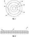
- An example of an optical fiber is shown in schematic cross-sectional view in FIG. 1 .
- Optical fiber 10 includes glass fiber 20 surrounded by primary coating 50 and secondary coating 60.
- Glass fiber 20 includes a core region 30 and a cladding region 40.
- secondary coating 60 may include a pigment. Further description of glass fiber 20, primary coating 50, and secondary coating 60 is provided below. Additionally, one or more tertiary ink layers may surround secondary coating 60.
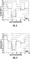
- FIG. 2 illustrates an optical fiber ribbon 15, which may include a plurality of optical fibers 10 and a matrix 70 encapsulating the plurality of optical fibers.
- optical fibers 10 are aligned relative to one another in a substantially planar and parallel relationship.
- the optical fibers in fiber optic ribbon 15 are encapsulated by the matrix 70 in any of several known configurations (e.g., edge-bonded ribbon, thin-encapsulated ribbon, thick-encapsulated ribbon, or multi-layer ribbon) by conventional methods of making fiber optic ribbons.
- Fiber optic ribbon 15 in the embodiment of FIG. 2 contains twelve (12) optical fibers 10.
- Matrix 70 has tensile properties similar to the tensile properties of a secondary coating and can be formed from the same, similar, or different composition used to prepare a secondary coating.
- FIG. 3 illustrates an optical fiber cable 17 that includes a plurality of optical fibers 10 surrounded by a jacket 80. Fibers 10 may be densely or loosely packed into a conduit enclosed by an inner surface 85 of jacket 80. The number of fibers placed in jacket 42 is referred to as the "fiber count" of optical fiber cable 40.
- Jacket 80 is formed from an extruded polymer material and may include multiple concentric layers of polymers or other materials.
- Optical fiber cable 17 may include one or more strengthening members (not shown) embedded within jacket 80 or placed within the conduit defined by inner surface 85. Strengthening members include fibers or rods that are more rigid than jacket 80. The strengthening member may be made from metal, braided steel, glass-reinforced plastic, fiber glass, or other suitable material.
- Optical fiber cable 17 may include other layers surrounded by jacket 80 such as, for example, armor layers, moisture barrier layers, rip cords, etc.
- optical fiber cable 40 may have a stranded, loose tube core or other fiber optic cable construction.
- glass fiber 20 includes core region 30 and cladding region 40.
- Core region 30 has a higher refractive index than cladding region 40, and glass fiber 20 functions as a waveguide.
- core region 30 and cladding region 40 have a discernible core-cladding boundary.
- core region 30 and cladding region 40 can lack a distinct boundary.
- cladding region 40 includes inner cladding region 42, first depressed-index cladding region 43, intermediate cladding region 44, second depressed-index cladding region 45, and outer cladding region 46.
- FIG. 5 plots an idealized relative refractive index profile of glass fiber 20 as the relative refractive index ⁇ versus the radial coordinate r.
- Inner cladding region 42 has a relative refractive index ⁇ 2 and a width W2.
- First depressed-index cladding region 43 can be in the form of a depressed region or a trench and has a width W3 and a relative refractive index ⁇ 3, with a minimum value ⁇ 3 MIN .
- Intermediate cladding region 44 has a relative refractive index ⁇ 4 and a width W4.
- Second depressed-index cladding region 45 can be in the form of a depressed region or a trench and has a width W5 and a relative refractive index ⁇ 5, with a minimum value ⁇ 5 MIN .
- Core region 30 comprises silica glass that is either undoped silica glass, up-doped silica glass, and/or down-doped silica glass.
- Up-doped silica glass includes silica glass doped with, for example, germanium (e.g., GeO 2 ), phosphorus (e.g., P 2 O 5 ), aluminum (e.g. Al 2 O 3 ), chlorine, or an alkali metal oxide (e.g. Na 2 O, K 2 O, Li 2 O, Cs 2 O, or Rb 2 O).
- the core comprises germania doped glass having a germania concentration between about 5 wt% and about 10 wt%.
- the peak concentration of the alkali in the silica glass may range from about 10 ppm to about 500 ppm, or from about 30 ppm to about 400 ppm.
- the silica glass of core region 30 is free of germanium and/or chlorine; that is the core region comprises silica glass that lacks germanium and/or chlorine.
- Down-doped silica glass includes silica glass doped with, for example, fluorine or boron.
- the relative refractive index of core region 30 of glass fiber 20 is described by an ⁇ -profile with an ⁇ value that is in a range of about 7.0 or less, or about 6.0 or less, or about 5.0 or less, or about 4.0 or less, or about 3.0 or less, or about 2.0 or less, or about 1.0 or less.
- the ⁇ value is about 8.0 or greater, or about 9.0 or greater, or about 10.0 or greater, or about 11.0 or greater, or about 12.0 or greater, or about 13.0 or greater.
- the core ⁇ value is less than 100, or less than 50, or less than 20.
- the ⁇ value is about 2.0, about 2.2, about 2.4, about 3.0, about 3.2, about 4.4, about 10.0, about 12.0, about 12.2, about 12.4, or about 20.
- the outer radius r 1 of core region 30 is in a range from about 3.0 microns to about 7.0 microns, or about 3.5 microns to about 6.5 microns, or about 4.0 microns to about 5.0 microns, or about 4.3 microns to about 5.7 microns. In some embodiments, the outer radius r 1 is about 4.2 microns, or about 4.3 microns, or about 4.4 microns, or about 4.5 microns, or about 5.3 microns, or about 5.4 microns, or about 5.5 microns, or about 5.6 microns.
- the maximum relative refractive index ⁇ 0 or ⁇ 1max of core region 30 is in a range from about 0.50% or less, or about 0.40% or less, or about 0.39% or less, or about 0.38% or less, or about 0.37% or less, or about 0.36% or less, or about 0.35% or less, or about 0.34% or less, or about 0.33% or less, or about 0.32% or less, or about 0.31% or less, or about 0.30% or less, or about 0.28% or less, or about 0.25% or less.
- the maximum relative refractive index ⁇ 0 or ⁇ 1max of core region 30 is about 0.10% or greater, or about 0.15% or greater, or about 0.20% or greater, or about 0.25% or greater, or about 0.30% or greater. In some embodiments, the maximum relative refractive index ⁇ 0 or ⁇ 1max is about 0.32%, or about 0.34%, or about 0.35%, or about 0.37%, or about 0.38%.
- the relative refractive index of core region 30 may have a centerline dip such that the maximum refractive index of core region 30 and the maximum refractive index of the entire optical fiber 10 is located a small distance away from the centerline of core region 30 rather than at the centerline of core region 30, as depicted in FIG. 5 .
- Inner cladding region 42 may be comprised of undoped silica glass.
- the inner radius of inner cladding region 42 is r 1 , as discussed above.
- the outer radius r 2 of inner cladding region 42 is in a range from about 6.5 microns to about 15.0 microns, or about 7.0 microns to about 14.0 microns, or about 7.5 microns to about 13.5 microns, or about 8.0 microns to about 12.0 microns, or about 9.0 microns to about 11.0 microns.
- the outer radius r 2 is about 7.2 microns, or about 7.5 microns, or about 8.9 microns, or about 9.1 microns, or about 10.0 microns, or about 10.6 microns, or about 11.5 microns, or about 11.7 microns, or about 14.0 microns.
- the relative refractive index ⁇ 2 of inner cladding region 42 is in a range from about - 0.20% to about 0.20%, or in a range from about -0.15% to about 0.15%, or in a range from about -0.10% to about 0.10%, or in a range from about -0.05% to about 0.05%. In some embodiments, the relative refractive index ⁇ 2 is about 0.0%. The relative refractive index ⁇ 2 is preferably constant or approximately constant.
- First depressed-index cladding region 43 comprises down-doped silica glass.
- first depressed-index cladding region 43 is down-doped with fluorine or boron.
- the down-doping of first depressed-index cladding region 43 can also be accomplished by incorporating voids in silica glass.
- the inner radius of first depressed-index cladding region 43 is r 2 , as discussed above.
- the outer radius r 3 of first depressed-index cladding region 43 is in a range of about 13.0 microns to about 23.0 microns, or about 13.5 microns to about 22.0 microns, or about 14.0 microns to about 21.0 microns, or about 14.5 microns to about 20.0 microns, or about 15.0 microns to about 19.0 microns, or about 15.5 microns to about 18.5 microns.
- the outer radius r 3 is about 14.2 microns, or about 14.6 microns, or about 15.9 microns, or about 15.6 microns, or about 17.0 microns, or about 17.1 microns, or about 18.0 microns, or about 20.0 microns.
- first depressed-index cladding region 43 is a depressed-index cladding region that forms a trench design.
- the trench design may be an offset trench.
- the relative refractive index ⁇ 3 of first-depressed index cladding region 43 is in a range from about - 0.10% to about -0.60%, or about -0.15% to about -0.55%, or about -0.20% to about -0.50%, or about -0.25% to about -0.45%, or about -0.30% to about -0.40%.
- the relative refractive index ⁇ 3 of first-depressed index cladding region 43 is about -0.10%, or about -0.20%, or about-0.25%, or about -0.30%, or about -0.45%, or about -0.50%, or about -0.55%.
- transition regions from inner cladding region 42 to first depressed-index cladding region 43 and from first depressed-index cladding region 43 to intermediate cladding region 44 are shown as step changes in FIG. 5 .
- a step change is an idealization and that transition regions may not be strictly vertical in practice. Instead, the transition regions may have a slope or curvature.
- the trench volume V 3 of first depressed-index cladding region 43 may be about 5.0 % ⁇ -micron 2 to about 70.0 % ⁇ -micron 2 , or about 30.0 % ⁇ -micron 2 to about 70.0 % ⁇ -micron 2 , or about 40.0 % ⁇ -micron 2 to about 60.0 % ⁇ -micron 2 , or about 50.0 % ⁇ -micron 2 to about 55.0 % ⁇ -micron 2 .
- the trench volume V 3 is about 5.5 % ⁇ -micron 2 , or about 8.7 % ⁇ -micron 2 , or about 15.1 % ⁇ -micron 2 , or about 20.1 % ⁇ -micron 2 , or about 25.7 % ⁇ -micron 2 , or about 27.7 % ⁇ -micron 2 , or about 50.5 % ⁇ -micron 2 , or about 50.8 % ⁇ -micron 2 , or about 50.9 % ⁇ -micron 2 or about 51.0 % ⁇ -micron 2 , or about 53.1 % ⁇ -micron 2 , or about 54.2 % ⁇ -micron 2 , or about 56.9 % ⁇ -micron 2 , or about 57.0 % ⁇ -micron 2 .
- the center of mass of the radial position of first depressed-index cladding region 43 is in a range between about 6.0 microns and about 20.0 microns, or about 7.0 microns and about 18.0 microns, or about 8.0 microns and about 17.0 microns, or about 10.0 microns and about 15.0 microns, or about 11.0 microns and about 14.0 microns, or about 12.0 microns and about 13.0 microns.
- the center of mass of the radial position of first depressed-index cladding region 43 is 11.9 microns, or 12.7 microns, or 13.3 microns.
- first depressed-index cladding region 43 may have either a rectangular or triangular profile.
- Intermediate cladding region 44 may be comprised of undoped silica glass.
- the inner radius of intermediate cladding region 44 is r 3 , as discussed above.
- the outer radius r4 of intermediate cladding region 44 is in a range from about 15.0 microns to about 26.0 microns, or about 16.0 microns to about 25.0 microns, or about 17.0 microns to about 22.0 microns, or about 18.0 microns to 21.0 microns.
- outer radius r4 of intermediate cladding region 44 is about 17.0 microns, or about 17.5 microns, or about 18.0 microns, or about 18.2 microns, or about 18.5 microns, or about 20.0 microns, or about 20.2 microns, or about 20.5 microns.
- the relative refractive index ⁇ 4 of intermediate cladding region 44 is in a range from about -0.20% to about 0.20%, or in a range from about -0.15% to about 0.15%, or in a range from about -0.10% to about 0.10%, or in a range from about -0.05% to about 0.05%. In some embodiments, the relative refractive index ⁇ 4 is about 0.0%. The relative refractive index ⁇ 4 is preferably constant or approximately constant. Furthermore, is some embodiments, the relative refractive index ⁇ 4 is equal to or substantially equal to the relative refractive index ⁇ 2 .
- Second depressed-index cladding region 45 comprises down-doped silica glass.
- second depressed-index cladding region 45 is down-doped with fluorine or boron.
- the down-dopant of second depressed-index cladding region 45 may be the same or different from the down-dopant of first depressed-index cladding region 43.
- the inner radius of second depressed-index cladding region 45 is r 4 , as discussed above.
- the outer radius r 5 of second depressed-index cladding region 45 is in a range of about 16.0 microns to about 30.0 microns, or about 17.0 microns to about 28.0 microns, or about 18.0 microns to about 26.0 microns, or about 19.0 microns to about 25.0 microns.
- the outer radius r 4 is about 17.0 microns, or about 17.4 microns, or about 18.0 microns, or about 20.0 microns, or about 24.4 microns or about 24.6 microns, or about 24.8 microns, or about 24.9 microns, or about 25.0 microns, or about 25.3 microns, or about 25.4 microns.
- second depressed-index cladding region 45 is a depressed-index cladding region that forms a trench design.
- the trench design may be an offset trench.
- the relative refractive index ⁇ 5 of second-depressed index cladding region 45 is in a range from about -0.004% to about -0.350%, or about -0.008% to about -0.300%, or about -0.020% to about -0.250%, or about -0.020% to about -0.200%, or about -0.060% to about -0.200%, or about - 0.080% to about -0.150%, or about -0.100% to about -0.125%.
- the relative refractive index ⁇ 5 of second depressed-index cladding region 45 is about -0.020%, or about -0.040%, or about -0.060%, or about -0.072%, or about -0.080%, or about -0.100%, or about -0.1100%, or about -0.120%, or about -0.180%, or about -0.145%, or about -0.200%, or about -0.250%, or about -0.300%.
- transition regions from intermediate cladding region 44 to second depressed-index cladding region 45 and from second depressed-index cladding region 45 to outer cladding region 46 are shown as step changes in FIG. 5 .
- a step change is an idealization and that transition regions may not be strictly vertical in practice. Instead, the transition regions may have a slope or curvature.
- the trench volume V 5 of second depressed-index cladding region 45 may be about 0.10 % ⁇ -micron 2 to about 50.0 % ⁇ -micron 2 , or from about 0.5 % ⁇ -micron 2 to about 40.0 % ⁇ -micron2, or from about 1.0 % ⁇ -micron 2 to about 30.0 % ⁇ -micron 2 , or from about 5.0 % ⁇ -micron 2 to about 25.0 % ⁇ -micron 2 , or from about 8.0 % ⁇ -micron 2 to about 23.0 % ⁇ -micron 2 .
- the trench volume V 5 is about 10.0 % ⁇ -micron 2 or less, or about 8.0 % ⁇ -micron 2 or less, or about 5.0 % ⁇ -micron 2 or less, or about 2.5 % ⁇ -micron 2 or less, or about 2.0 % ⁇ -micron 2 or less, or about 1.0 % ⁇ -micron 2 or less, or about 0.75 % ⁇ -micron 2 or less, or about 0.5 % ⁇ -micron 2 or less, or about 0.25 % ⁇ -micron 2 or less, or about 0.2 % ⁇ -micron 2 or less, or about 0.1 % ⁇ -micron 2 or less.
- the trench volume V 5 is about 7.74 % ⁇ -micron 2 , or about 8.22 % ⁇ -micron 2 , or about 8.48 % ⁇ -micron 2 , or about 11.82 % ⁇ -micron 2 , or about 12.32 % ⁇ -micron 2 , or about 12.72 % ⁇ -micron 2 , or about 13.83 % ⁇ -micron 2 , or about 15.58 % ⁇ -micron 2 , or about 16.43 % ⁇ -micron 2 , or about 16.96 % ⁇ -micron 2 , or about 18.43 % ⁇ -micron 2 , or about 19.34 % ⁇ -micron 2 , or about 20.54 % ⁇ -micron 2 , or about 21.20 % ⁇ -micron2, or about 21.70 % ⁇ -micron 2 , or about 23.04 % ⁇ -micron 2 , or about 25.44 % ⁇ -micron 2 .
- the center of mass of the radial position of second depressed-index cladding region 45 is in a range between about 15.0 microns and about 35.0 microns, or about 15.5 microns and about 32.0 microns, or about 16.0 microns and about 30.0 microns, or about 18.0 microns and about 28.0 microns, or about 20.0 microns and about 25.0 microns, or about 21.0 microns and about 24.0 microns, or about 16.0 microns and about 18.0 microns.
- the center of mass of the radial position of second depressed-index cladding region 45 is about 22.6 microns, or about 22.9 microns, or about 23.3 microns.
- a ratio of the center of mass of the radial position of first depressed-index cladding region 43 to second depressed-index cladding 45 is in a range from about 0.25 to about 0.75, or about 0.30 to about 0.70, or about 0.35 to about 0.65, or about 0.40 to about 0.60. In some embodiments, the ratio is about 0.52, or about 0.53, or about 0.54, or about 0.56, or about 0.57, or about 0.59.
- second depressed-index cladding region 45 may have either a rectangular or triangular profile.
- Outer cladding region 46 may be comprised of undoped silica glass.
- the inner radius of outer cladding region 46 is r 5 , as discussed above.
- the outer radius r 6 of outer cladding region 46 is in a range from about 40.0 microns to about 65 microns, or from about 45.0 microns to about 62.5 microns, or from about 50.0 microns to about 60.0 microns, or from about 52.5 microns to about 57.5 microns. In some embodiments, the outer radius r 6 of outer cladding region 46 is about 62.5 microns.
- the relative refractive index ⁇ 6 of inner cladding region 42 is in a range from about - 0.20% to about 0.20%, or in a range from about -0.15% to about 0.15%, or in a range from about -0.10% to about 0.10%, or in a range from about -0.05% to about 0.05%. In some embodiments, the relative refractive index ⁇ 6 is about 0.0%. The relative refractive index ⁇ 6 is preferably constant or approximately constant. Furthermore, is some embodiments, the relative refractive index ⁇ 6 is equal to or substantially equal to the relative refractive index ⁇ 2 and/or the relative refractive index ⁇ 4 .
- first and second depressed-index cladding regions 43, 45 can have either a rectangular or a triangular profile.
- both depressed-index cladding regions 43, 45 have a rectangular profile.
- both depressed-index cladding regions 43, 45 have a triangular profile.
- at least one of the depressed index-cladding regions 43, 45 has a rectangular profile and at least one has a triangular profile.
- the triangular shape of either first depressed-index cladding region 43 and/or second depressed-index cladding region 45 may be such that the refractive index decreases with increasing radial position. Therefore, the trench volume of the triangular trenches increases with increasing radial position.
- the volume V 3 of first depressed-index cladding region 43 is greater than the volume V 5 of second depressed-index cladding region 45.
- a ratio V 5 /V 3 is less than 1.0, or about 0.9 or less, or about 0.8 or less, or about 0.7 or less, or about 0.6 or less, or about 0.5 or less, or about 0.4 or less, or about 0.3 or less, or about 0.2 or less, or about 0.1 or less.
- the volume V 3 is less than the volume V 5 . It is also contemplated that the volumes V 3 and V 5 are equal or substantially equal to each other.
- both first and second depressed-index cladding regions 43, 45 have a rectangular profile and the ratio V 5 /V 3 is about 0.2, or about 0.3, or about 0.4.
- first depressed-index cladding region 43 has a triangular profile
- second depressed-index cladding region 45 has a rectangular profile
- the ratio V 5 /V 3 is about 0.1, or about 0.2, or about 0.3, or about 0.4.
- first and second depressed-index cladding regions 43, 45 i.e., dual trench design
- first and second depressed-index cladding regions 43, 45 are optimized to maintain a cable cutoff that meets the G.657 standards.
- Primary coating 50 immediately surrounds glass fiber 20, and secondary coating 60 immediately surrounds primary coating 50.
- primary coating 50 comprises a low modulus material and second coating 60 comprises a high modulus material.
- One or more of the materials may be, for example, acrylate.
- Optical fiber 10 may also include a tertiary coating that surrounds secondary coating 60.
- the tertiary coating may include pigments, inks, or other coloring agents to mark the optical fiber for identification purposes and typically has a Young's modulus similar to the Young's modulus of the secondary coating.
- An outer diameter of secondary coating 60 is an outer diameter of optical fiber 10, when a tertiary layer is not applied.
- the outer diameter of secondary coating 60 may be about 250 microns or less, or about 220 microns or less, or about 210 microns or less, or about 200 microns or less, or about 190 microns or less, or about 180 microns or less, or about 170 microns or less.
- optical fibers disclosed herein have good reduced bend sensitivity across all bend diameter (e.g., 15 mm, 20 mm, 30 mm). Thus, the optical fibers disclosed herein meet the G.657 bend loss standards across all these bend diameters. These bend loss standards are achieved while maintaining a high mode field diameter, in contrast to conventional fibers.
- the optical fibers disclosed herein have a bend loss at 1550 nm, as determined by the mandrel wrap test having a diameter of 15 mm, of less than about 0.75 dB/turn, or less than about 0.50 dB/turn, or less than about 0.25 dB/turn, or less than about 0.20 dB/turn, or less than about 0.15 dB/turn, or less than about 0.14 dB/turn, or less than about 0.13 dB/turn, or less than about 0.12 dB/turn, or less than about 0.11 dB/turn, or less than about 0.10 dB/turn, or less than about 0.09 dB/turn, or less than about 0.08 dB/turn, or less than about 0.07 dB/turn, or less than about 0.06 dB/turn, or less than about 0.06 dB/turn.
- the optical fibers disclosed herein have a bend loss at 1550 nm, as determined by the mandrel wrap test having a diameter of 20 mm, of less than about 0.20 dB/turn, or less than about 0.15 dB/turn, or less than about 0.10 dB/turn, or less than about 0.08 dB/turn, or less than about 0.06 dB/turn, or less than about 0.05 dB/turn, or less than about 0.04 dB/turn, or less than about 0.03 dB/turn, or less than about 0.02 dB/turn, or less than about 0.01 dB/turn, or less than about 0.009 dB/turn , or less than about 0.008 dB/turn, or less than about 0.007 dB/turn, or less than about 0.006 dB/turn, or less than about 0.005 dB/turn, or less than about 0.004 dB/turn.
- the optical fibers disclosed herein have a bend loss at 1550 nm, as determined by the mandrel wrap test having a diameter of 30 mm, of less than about 0.0060 dB/turn, or less than about 0.0050 dB/turn, or less than about 0.0040 dB/turn, or less than about 0.0035 dB/turn, or less than about 0.0030 dB/turn, or less than about 0.0025 dB/turn, or less than about 0.0024 dB/turn, or less than about 0.0023 dB/turn, or less than about 0.0021 dB/turn, or less than about 0.0020 dB/turn, or less than about 0.0019 dB/turn, or less than about 0.0018 dB/turn, or less than about 0.0017 dB/turn, or less than about 0.0016 dB/turn, or less than about 0.0015 dB/turn, or less than about 0.0014 dB/turn, or less than about 0.0013
- first depressed-index cladding region 43 provides the G.657 compliant bend losses at smaller bend diameters (e.g., ⁇ 25 mm) and the location and trench volume of second depressed-index cladding region 45 provides the G.657 compliant bend losses at larger bend diameters (e.g., > 25 mm).
- position of the second trench (second depressed-index cladding region 45) is chosen such that it has minimal or zero effect on the cable cutoff and does not negatively impact other optical properties (such as effective area, dispersion, etc.).
- the optical fibers disclosed herein also have a mode field diameter, at 1310 nm wavelength, in range of about 8.9 microns or greater, or about 9.0 microns or greater, or about 9.1 microns or greater, or about 9.2 microns or greater, or about 9.3 microns or greater, or about 9.4 microns or greater, or about 9.5 microns or greater.
- the mode field diameter is in a range from about 8.9 microns to about 9.7 microns, or from about 9.0 microns to about 9.6 microns.
- the mode field diameter is about 9.07 microns, about 9.08 microns, about 9.23 microns, about 9.26 microns, or about 9.27 microns at 1310 nm wavelength.
- the cable cutoff of the optical fibers disclosed herein is about 1300 nm or less, or about 1260 nm or less, or about 1250 nm or less, or about 1240 nm or less, or about 1230 nm or less, or about 1220 nm or less, or about 1210 nm or less, or about 1205 nm or less, or about 1200 nm or less, or about 1195 nm or less, or about 1190 nm or less, or about 1185 nm or less, or about 1180 nm or less, or about 1175 nm or less, or about 1170 nm or less.
- the cable cutoff is about 1227 nm, about 1226 nm, about 1222 nm, about 1220 nm, about 1218 nm, about 1216 nm, about 1215 nm, about 1205 nm, about 1203 nm, about 1200 nm, about 1180 nm, or about 1176 nm.
- the optical fibers disclosed herein have an effective area, at 1310 nm wavelength, of about 70.0 micron 2 or less, or about 69.0 micron 2 or less, or about 68.0 micron 2 or less, or about 67.0 micron 2 or less, or about 66.0 micron 2 or less, or about 65.0 micron 2 or less, or about 64.0 micron 2 or less, or about 63.0 micron 2 or less, or about 62.0 micron 2 or less, or about 61.0 micron 2 or less, or about 60.0 micron 2 or less.
- the optical fibers also have an effective area, at 1550 nm wavelength, of about 75 micron 2 or greater, or about 78 micron 2 or greater, or about 80 micron 2 or greater.
- the effective area, at 1550 nm wavelength is about 95 micron 2 or less, or about 90 micron 2 or less, or about 85 micron 2 or less. In some embodiments, the effective area, at 1550 nm wavelength, is in range between 75 micron 2 and about 90 micron 2 .
- the optical fibers disclosed herein also have zero dispersion wavelength from about 1290 nm to about 1330 nm.
- the zero dispersion wavelength can be from about 1295 nm to about 1325 nm, about 1300 nm to about 1324 nm, or from about 1305 nm to about 1315 nm.
- the zero dispersion wavelength can be about 1280 nm, about 1285 nm, about 1289 nm, about 1290 nm, about 1300 nm, about 1301 nm, about 1305 nm, about 1306 nm, about 1310 nm, about 1315 nm, or about 1320 nm.
- the attenuation of the optical fibers disclosed herein is less than or equal to about 0.35 dB/km at 1310 nm wavelength, less than or equal to about 0.2 dB/km at 1550 nm wavelength, and less than or equal to about 0.35 dB/turn at 1625 nm wavelength. In some embodiments, the attenuation is less than or equal to about 0.19 dB/turn, or less than or equal to about 0.18 dB/turn, or less than or equal to about 0.185 dB/turn at 1550 nm wavelength.
- the optical fibers have a dispersion having an absolute value at 1310 nm in a range between about -3 ps/nm/km and about 3 ps/nm/km and a dispersion slope at 1310 nm in a range between about 0.085 ps/nm 2 /km and 0.095 ps/nm 2 /km.
- the absolute value of the dispersion at 1310 nm can be from about 2 ps/nm/km to about 2 ps/nm/km,, about 1.5 ps/nm/km to about 1.5 ps/nm/km, about 1.5 ps/nm/km to about 1 ps/nm/km.
- the absolute value of the dispersion at 1310 can be about 1.2 ps/nm/km, about 0.1 ps/nm/km, about 0.7 ps/nm/km, about 0.4 ps/nm/km, about 0.2 ps/nm/km, about 0.0 ps/nm/km, about 0.2 ps/nm/km, about 0.4 ps/nm/km, about 0.6 ps/nm/km, about 0.8 ps/nm/km, about 0.9 ps/nm/km, or any value between these values.
- the dispersion slope at 1310 nm can be about 0.07 ps/nm 2 /km to about 0.1 ps/nm 2 /km, about 0.08 ps/nm 2 /km to about 0.1 ps/nm 2 /km, about 0.085 ps/nm 2 /km to about 0.1 ps/nm 2 /km, about 0.09 ps/nm 2 /km to about 0.1 ps/nm 2 /km, about 0.075 ps/nm 2 /km to about 0.09 ps/nm 2 /km, about 0.08 ps/nm 2 /km to about 0.09 ps/nm 2 /km, or about 0.085 ps/nm 2 /km to about 0.09 ps/nm 2 /km.
- the dispersion slope at 1310 nm can be about 0.075 ps/nm 2 /km, about 0.08 ps/nm 2 /km, about 0.085 ps/nm 2 /km, about 0.086 ps/nm 2 /km, about 0.087 ps/nm 2 /km, about 0.088 ps/nm 2 /km, about 0.089 ps/nm 2 /km, about 0.09 ps/nm 2 /km, or about 0.01 ps/nm 2 /km.
- the optical fibers have a dispersion at 1550 nm of less than 22 ps/nm/km and a dispersion slope at 1550 nm of less than 0.1 ps/nm 2 /km.
- the dispersion at 1550 nm can be from about 10 ps/nm/km to about 22 ps/nm/km, about 10 ps/nm/km to about 22 ps/nm/km, about 10 ps/nm/km to about 20 ps/nm/km, about 10 ps/nm/km to about 15 ps/nm/km, about 15 ps/nm/km to about 22 ps/nm/km, or about 15 ps/nm/km to about 20 ps/nm/km.
- the dispersion at 1550 can be about 10 ps/nm/km, about 15 ps/nm/km, about 16 ps/nm/km, about 17 ps/nm/km, about 17.5 ps/nm/km, about 18 ps/nm/km, about 19 ps/nm/km, about 19.5 ps/nm/km, about 19.6 ps/nm/km, about 20 ps/nm/km, about 20.1 ps/nm/km, about 22 ps/nm/km, or any value between these values.
- the dispersion slope at 1550 nm can be about 0.04 ps/nm 2 /km to about 0.1 ps/nm 2 /km, about 0.05 ps/nm 2 /km to about 0.1 ps/nm 2 /km, about 0.055 ps/nm 2 /km to about 0.1 ps/nm 2 /km, about 0.06 ps/nm 2 /km to about 0.1 ps/nm 2 /km, about 0.08 ps/nm 2 /km to about 0.1 ps/nm 2 /km, about 0.04 ps/nm 2 /km to about 0.08 ps/nm 2 /km, about 0.05 ps/nm 2 /km to about 0.08 ps/nm 2 /km, about 0.055 ps/nm 2 /km to about 0.08 ps/nm 2 /km, about 0.06 ps/nm 2 /n, about
- the dispersion slope at 1550 nm can be about 0.04 ps/nm 2 /km, about 0.05 ps/nm 2 /km, about 0.055 ps/nm 2 /km, about 0.057 ps/nm 2 /km, about 0.058 ps/nm 2 /km, about 0.059 ps/nm 2 /km, about 0.06 ps/nm 2 /km, about 0.061 ps/nm 2 /km, about 0.07 ps/nm 2 /km, or about 0.08 ps/nm 2 /km.
- the exemplary embodiments shown below have a dual trench design with a mode field diameter at 1310 nm of 9 microns or greater, a cable cutoff of less than or equal to 1260 nm, and zero dispersion wavelength between 1300 nm and 1324 nm.
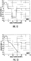
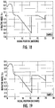
- Table 1 below provides four exemplary embodiments (Ex 1-4) and a comparative example (C1). Exemplary embodiments Ex 1-4 are shown in FIGS. 6-9 . Exemplary embodiments Ex 1-4 all have a dual trench design with two rectangular shaped depressed-index cladding regions, a peak core refractive index ( ⁇ 1 max ) of 0.336%, and a core alpha of 12. Although comparative example C1, which only has a single depressed-index cladding region, has the same mode field diameter of exemplary embodiments Ex 1-4, comparative example C1 does not meet the G.657 standards across all bend diameters. More specifically, comparative example C1 does not meet the 30 mm bend loss standard.
- Table 2 below provides three exemplary embodiments (Ex 5-7), which are also shown in FIGS. 10-12 .
- Exemplary embodiments Ex 5-7 all have a dual trench design with two rectangular shaped depressed-index cladding regions, a peak core refractive index ( ⁇ 1 max ) of 0.317%, and a core alpha of 12.
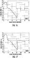
- Table 3 below provides four exemplary embodiments (Ex 8-11), which are also shown in FIGS. 13-16 .
- Exemplary embodiments Ex 8-11 all have a dual trench design with both a triangular and a rectangular shaped depressed-index cladding region, a peak core refractive index ( ⁇ 1 max of 0.336%, and a core alpha of 12.
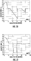
- Table 4 below provides four exemplary embodiments (Ex 12-15), which are also shown in FIGS. 17-20 .
- Exemplary embodiments Ex 12-15 all have a dual trench design with two triangular shaped depressed-index cladding regions, a peak core refractive index ( ⁇ 1 max ) of 0.336%, and a core alpha of 12.
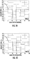
- Table 5 below provides five exemplary embodiments (Ex 16-20) and a comparative example (C2). Exemplary embodiments Ex 16-20 are shown in FIGS. 21-25 . Exemplary embodiments Ex 16-20 all have a dual trench design with two rectangular shaped depressed-index cladding regions, a peak core refractive index ( ⁇ 1 max ) of 0.37%, and a core alpha of 2.2. Although comparative example C2, which only has a single depressed-index cladding region, has a similar mode field diameter of exemplary embodiments Ex 16-20, comparative example C2 does not meet the G.657 standards across all bend diameters. More specifically, comparative example C2 does not meet the 30 mm bend loss standards.
- Table 6 below provides four exemplary embodiments (Ex 21-24) and a comparative example (C3).
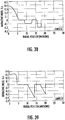
- Exemplary embodiments Ex 21-24 are shown in FIGS. 26-29 .
- Exemplary embodiments Ex 21-24 all have a dual trench design with both rectangular and triangular shaped depressed-index cladding regions, a peak core refractive index ( ⁇ 1 max ) of 0.37%, and a core alpha of 2.2.
- comparative example C3 which only has a single depressed-index cladding region, has the same mode field diameter of exemplary embodiments Ex 21-24, comparative example C3 does not meet the G.657 standards across all bend diameters. More specifically, comparative example C3 does not meet the 30 mm bend loss standards.
- Table 7 below provides four exemplary embodiments (Ex 25-28), which are also shown in FIGS. 30-33 .
- Exemplary embodiments Ex 25-28 all have a dual trench design with triangular shaped depressed-index cladding regions, a peak core refractive index ( ⁇ 1 max ) of 0.37%, and a core alpha of 2.2.
- Table 8 below provides five additional exemplary embodiments (Ex 29-33), which are also shown in FIGS. 34-38 .
- Exemplary embodiments Ex 29-33 all have a dual trench design with triangular and/or rectangular depressed-index cladding regions.
- Table 8 Ex29 Ex30 Ex31 Ex32 Ex33 Maximum Core Index, ⁇ 1max (%) 0.352 0.352 0.352 0.38 Core Radius, r 1 , microns 4.425 4.425 4.5 4.5 5.6 Core alpha 20 20 20 20 20 20 20 2.2 Inner Cladding Index, ⁇ 2 (%) 0 0 0 0 0 Inner Cladding 10 10 11.5 11.7 8.9 Radius, r 2 (microns) First Depressed-Index Cladding Shape Triangular Triangular Rectangular Rectangular Rectangular First Depressed-Index Cladding Minimum Index, ⁇ 3,min (%) -0.4 -0.3 -0.3 -0.1 -0.1 First Depressed-Index Cladding Outer Radius, r 3 (micron) 17.1 17
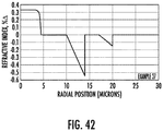
- Table 9 below provides four additional exemplary embodiments (Ex 34-37), which are also shown in FIGS. 39-42 .
- Exemplary embodiments Ex 34-37 all have a dual trench design with triangular and/or rectangular depressed-index cladding regions.
- Table 9 Ex34 Ex35 Ex36 Ex37 Maximum Core Index, ⁇ 1max (%) 0.324 0.324 0.3265 0.3265 Core Radius, r 1 , microns 4.36 4.36 4.382 4.382 Core alpha 20 20 20 20 20 20 First Inner Cladding Index, ⁇ 2 (%) 0 0 0 0 First Inner Cladding Radius, r 2 (microns) 10 10 10 10 First Depressed Cladding Shape Triangular Triangular Triangular Triangular First Depressed Cladding Minimum Index, ⁇ 3,min (%) -0.4 -0.51 -0.4 -0.55 First Depressed Cladding Outer Radius, r 3 (micron) 14 14 14 14 14 14 14 14 14 14 14 14 14 14 14 14 14 14 14 14 14 14 14 14 Volume of
- the optical fibers disclosed herein, with the dual trench designs can be made using well-known and conventional methods of making optical fiber.
- the refractive index profiles comprising rectangular trenches are made using OVD or VAD processes involving unique steps.
- the core region and the inner cladding region are deposited as soot to make a soot core preform, which is then subsequently moved to a consolidation furnace where it is treated with a dehydration agent and sintered into a void free fully densified core glass preform.
- the process to make the core glass preform also includes redrawing the soot core preform into daughter core canes.
- a silica soot layer is then put on the daughter core canes such that a thickness of the silica soot layer corresponds to a thickness of the first depressed-index cladding region in the optical fiber profile.
- the silica soot layer is then dehydrated, doped with fluorine, and sintered into a fully densified glass layer in the consolidation furnace.
- the intermediate cladding region, the second depressed-index cladding region, and the outer cladding region are deposited on the daughter core canes and consolidated to fully densified glass layers to complete the refractive index profile of the dual trench optical fibers disclosed here.
- Making of the second depressed-index cladding region is again achieved using fluorine doping in the consolidation furnace during processing of the second depressed-index cladding region.
- the refractive index profiles comprising triangular trenches can be made using a reduced number of steps compared to the rectangular trenches.
- the core region, the inner cladding region, and the first depressed-index cladding region are made in a single step.
- a germania doped core region with surrounding silica layer, which corresponds to a thickness of the inner cladding region and the first depressed-index cladding region, are deposited in laydown in a single step to produce a soot core preform.
- the soot core preform is then transferred to a consolidation furnace where it is treated with a dehydration agent, doped with fluorine, and consolidated into a void free fully densified glass preform.
- the fluorine doping of the soot core preform is performed under conditions where the fluorine doping is diffusion limited and is limited to a region corresponding to a depressed-index cladding region that is triangular in shape. In these embodiments, the fluorine doping is performed at a temperature greater than about 1275 ⁇ , or greater than about 1300 ⁇ , or greater than about 1325 ⁇ , or greater than about 1350 ⁇ , or less than about 1375 ⁇ . Furthermore, in these embodiments, the soot core preform is further processed by deposition of a silica soot layer that provides a soot thickness corresponding to a combined thickness of the intermediate cladding region and the second depressed-index cladding region.
- the soot core preform with the silica soot layer is then transferred to a consolidation furnace and treated with a dehydration agent, doped with fluorine, and sintered into a fully densified glass layer in the consolidation furnace, wherein the fluorine doping is performed at doping temperatures greater than about 1275 ⁇ to form the triangular depressed-index cladding region.
- a soot layer corresponding to the outer cladding region is then deposited on the soot core preform (which comprises the dual trench profile) and then transferred to a consolidated furnace, where it is sintered into a void free fully densified glass layer to form the optical fiber preform.
- the optical fiber preform is then drawn into an optical fiber, which may be used in telecommunication systems.
Landscapes
- Physics & Mathematics (AREA)
- General Physics & Mathematics (AREA)
- Optics & Photonics (AREA)
- Chemical & Material Sciences (AREA)
- Dispersion Chemistry (AREA)
- Optical Fibers, Optical Fiber Cores, And Optical Fiber Bundles (AREA)
- Manufacture, Treatment Of Glass Fibers (AREA)
- Lasers (AREA)
Abstract
Description
- This disclosure pertains to optical fibers. More particularly, this disclosure pertains to optical fibers with reduced bend loss across all bend diameters and to optical fibers with a dual trench design.
- Optical fibers having low bending loss are widely used in telecommunication systems, particularly in Fiber to the Premises (FTTP) applications, including Fiber to the Home (FTTH) and Fiber to the Building (FTTB) applications. Such applications generally require optical fibers with low bending loss of the optical signal transmitted therethrough, due to the strict installation constraints. For example, the optical fibers are drawn around tight corners in houses or buildings or experience radial compression that may adversely affect the performance or reliability of the optical fibers.
- The ITU-T Recommendation G.657 is used as the standard for bending-loss insensitive single mode optical fibers, in which the bending loss is reduced compared to a standard ITU-T G.652 compliant single mode optical fiber.
- In order to be ITU-T G.657 compliant at across all bend diameters, traditional single mode optical fibers have small mode field diameters to provide the required bend-loss insensitivity. Typically, the small mode field diameters are between 8.5 microns and 8.8 microns at 1310 nm. However, such small mode field diameters impair connectivity of these optical fibers when the fibers are connected to a standard single mode optical fiber having nominal mode field diameter of about 9.2 microns at 1310 nm wavelength. Such adversely results in increased connectivity losses.
- In order to have good bend insensitivity while reducing the connectivity losses, it is desirable to have a mode field diameter larger than or equal to 9 microns at 1310 nm wavelength and bend performance that is G.657 compliant for both smaller and larger bends. The optical fibers of the present disclosure that have a mode field diameter larger than or equal to 9 microns are G.657 compliant across all bend diameters. The embodiments of the present disclosure include optical fibers with a dual trench design to provide the G.657 compliant bend diameters for both smaller and larger bends while maintaining a mode field diameter of 9 microns or greater at 1310 nm wavelength.
- In a first aspect, the present disclosure includes a single mode optical fiber comprising a core region having an outer radius r1 and a maximum relative refractive index Δ1max. The single mode optical fiber has a bend loss at 1550 nm for a 15 mm diameter mandrel of less than about 0.75 dB/turn, has a bend loss at 1550 nm for a 20 mm diameter mandrel of less than about 0.2 dB/turn, and a bend loss at 1550 nm for a 30 mm diameter mandrel of less than 0.002 dB/turn. Additionally, the single mode optical fiber has a mode field diameter of 9.0 microns or greater at 1310 nm wavelength and a cable cutoff of less than or equal to about 1260 nm.
- In another aspect, the present disclosure includes a single mode optical fiber comprising a core region having an outer radius r1 and a maximum relative refractive index Δ1max and a cladding region surrounding the core region. The cladding region comprising an inner cladding region having an outer radius r2 and a relative refractive index Δ2; a first depressed-index cladding region surrounding the inner cladding region, the first depressed-index cladding region having an outer radius r3, a minimum relative refractive index Δ3min, and a trench volume V3; an intermediate cladding region surrounding the first depressed-index cladding region, the intermediate cladding region having an outer radius r4 and a relative refractive index Δ4; a second depressed-index cladding region surrounding the intermediate cladding region, the second depressed-index cladding region having an outer radius r5, a minimum relative refractive index Δ5min, and a trench volume V5; and an outer cladding region surrounding the second depressed-index cladding region, the outer cladding region having a relative refractive index Δ6. The single mode optical fiber has a bend loss at 1550 nm for a 15 mm diameter mandrel of less than about 0.75 dB/turn, has a bend loss at 1550 nm for a 20 mm diameter mandrel of less than about 0.2 dB/turn, and a bend loss at 1550 nm for a 30 mm diameter mandrel of less than about 0.005 dB/turn. Additionally, the single mode optical fiber has a mode field diameter of 9.0 microns or greater at 1310 nm wavelength.
- The disclosure also includes the following clauses:
- 1. A single mode optical fiber comprising:
- a core region having an outer radius r1 and a maximum relative refractive index Δ1max,
- wherein the single mode optical fiber has,
- a bend loss at 1550 nm for a 15 mm diameter mandrel of less than about 0.75 dB/turn,
- a bend loss at 1550 nm for a 20 mm diameter mandrel of less than about 0.2 dB/turn,
- a bend loss at 1550 nm for a 30 mm diameter mandrel of less than about 0.005 dB/turn,
- preferably a bend loss at 1550 nm for a 30 mm diameter mandrel of less than about 0.002 dB/turn,
- and
- wherein the single mode optical fiber has a mode field diameter of about 9.0 microns or
- greater at 1310 nm wavelength.
- 2. The single mode optical fiber of
clause 1 having a cable cutoff of less than or equal to about 1260 nm. - 3. The single mode optical fiber of
clause - 4. The single mode optical fiber of any of the clauses 1-3, wherein the mode field diameter is less than about 9.6 microns.
- 5. The single mode optical fiber of any of the preceding clauses, wherein the optical fiber cable has zero dispersion wavelength between about 1300 nm and about 1324 nm.
- 6. The single mode optical fiber of any of the preceding clauses, wherein the bend loss at 1550 nm for a 15 mm diameter mandrel is less than about 0.5 dB/turn.
- 7. The single mode optical fiber of any of the preceding clauses, wherein the bend loss at 1550 nm for a 15 mm diameter mandrel is less than about 0.25 dB/turn.
- 8. The single mode optical fiber of any of the preceding clauses, wherein the bend loss at 1550 nm for a 20 mm diameter mandrel is less than about 0.15 dB/turn.
- 9. The single mode optical fiber of any of the preceding clauses, wherein the bend loss at 1550 nm for a 20 mm diameter mandrel is less than about 0.1 dB/turn.
- 10. The single mode optical fiber of any of the preceding clauses,
wherein the bend loss at 1550 nm for a 30 mm diameter mandrel is less than about 0.0035 dB/turn,
or
wherein the bend loss at 1550 nm for a 30 mm diameter mandrel is less than about 0.0030 dB/turn, or
wherein the bend loss at 1550 nm for a 30 mm diameter mandrel is less than about 0.0021 dB/turn. - 11. The single mode optical fiber any of the preceding clauses, wherein the bend loss at 1550 nm for a 30 mm diameter mandrel is less than about 0.0018 dB/turn.
- 12. The single mode optical fiber of any of the preceding clauses, wherein the bend loss at 1550 nm for a 30 mm diameter mandrel is less than about 0.0013 dB/turn.
- 13. The single mode optical fiber of any of the preceding clauses, wherein the core region has an alpha value of less than or equal to about 5.
- 14. The single mode optical fiber of any of the preceding clauses 1-12, wherein the core region has an alpha value of greater than or equal to about 10.
- 15. The single mode optical fiber of any of the preceding clauses, wherein the optical fiber has an attenuation at 1550 nm of about 0.19 dB/km or less.
- 16. The single mode optical fiber of any of the preceding clauses, wherein the optical fiber has an attenuation at 1550 nm of about 0.18 dB/km or less.
- 17. The single mode optical fiber of any of the preceding clauses, further comprising a cladding region including a first depressed-index cladding region and a second depressed-index cladding region.
- 18. The single mode optical fiber according to any of the preceding clauses 1-16, further comprising:
a cladding region surrounding the core, the cladding region comprising:- an inner cladding region having an outer radius r2 and a relative refractive index Δ2,
- a first depressed-index cladding region surrounding the inner cladding region, the first depressed-index cladding region having an outer radius r3, a minimum relative refractive index Δ3min, and a trench volume V3,
- an intermediate cladding region surrounding the first depressed-index cladding region, the intermediate cladding region having an outer radius r4 and a relative refractive index Δ 4,
- a second depressed-index cladding region surrounding the intermediate cladding region, the second depressed-index cladding region having an outer radius r5, a minimum relative refractive index Δ5min, and a trench volume V5, and
- an outer cladding region surrounding the second depressed-index cladding region, the outer cladding region having a relative refractive index Δ6.
- 19. The single mode optical fiber of
clause 18, wherein:- Δ1max > Δ2 > Δ5min > Δ3min, and
- Δmax > Δ4 > Δ5min > Δ3min.
- 20. The single mode optical fiber of any of the clauses 18-19, wherein a ratio of V5/V3 is about 0.5 or less.
- 21. The single mode optical fiber of any of the clauses 18-20, wherein the ratio V5/V3 is about 0.4 or less.
- 22. The single mode optical fiber of any of the clauses 18-21, wherein the ratio V5/V3 is about 0.3 or less.
- 23. The single mode optical fiber of any of the clauses 18-22, wherein the trench volume V3 is between about 15.0 %Δ-micron2 and about 70.0 %Δ-micron2.
- 24. The single mode optical fiber of any of the clauses 18-23, wherein the trench volume V3 is between about 15.0 %Δ-micron2 and about 57.0 %Δ-micron2.
- 25. The single mode optical fiber of any of the clauses 18-24,
wherein the trench volume V5 is between about 6.0 %Δ-micron2 and about 30.0 %Δ-micron2. - 26. The single mode optical fiber of any of the clauses 18-25, wherein the trench volume V5 is between about 6.0 %Δ-micron2 and about 24.0 %Δ-micron2.
- 27. The single mode optical fiber of any of the clauses 18-26,
wherein the minimum relative refractive index Δ5min is between about -0.01% and about -0.3%, or
wherein the minimum relative refractive index A5min is between about -0.02% and about -0.2%, or
wherein the minimum relative refractive index Δ5min is between about -0.04% and about -0.15%. - 28. The single mode optical fiber of any of the preceding clauses 18-27, wherein at least one of the first depressed-index cladding region and the second depressed-index cladding region has a refractive index profile that is rectangular in shape.
- 29. The single mode optical fiber of any of the preceding clauses 18-28, wherein at least one of the first depressed-index cladding region and the second depressed-index cladding region has a refractive index profile that is triangular in shape.
- 30. The single mode optical fiber any of the preceding clauses 18-29, wherein at least one of the first depressed-index cladding region and the second depressed-index cladding region has a refractive index profile that has a decreasing refractive index with increased radial position.
- 31. The single mode optical fiber of any of the preceding clauses 18-30, wherein a center of mass of a radial position of the first depressed-index cladding region is between about 7.0 microns and about 18.0 microns.
- 32. The single mode optical fiber of any of the preceding clauses 18-31, wherein the center of mass of the radial position of the first depressed-index cladding region is between about 8.0 microns and about 17.0 microns.
- 33. The single mode optical fiber of any of the preceding clauses 18-32, wherein the center of mass of the radial position of the first depressed-index cladding region is between about 10.0 microns and about 15.0 microns.
- 34. The single mode optical fiber of any of the preceding clauses 18-33, wherein a center of mass of a radial position of the second depressed-index cladding region is between about 15.0 microns and about 35.0 microns.
- 35. The single mode optical fiber of any of the preceding clauses 18-34, wherein the center of mass of the radial position of the second depressed-index cladding region is between about 16.0 microns and about 30.0 microns.
- 36. The single mode optical fiber of any of the preceding clauses 18-35, wherein the center of mass of the radial position of the second depressed-index cladding region is between about 18.0 microns and about 28.0 microns.
- 37. The single mode optical fiber of any of the preceding clauses 18-36, wherein a ratio of a central radial position of the first depressed-index cladding region to a central radial position of the second depressed-index cladding region is between about 0.35 to about 0.65.
- Additional features and advantages will be set forth in the detailed description which follows, and in part will be readily apparent to those skilled in the art from the description or recognized by practicing the embodiments as described in the written description and claims hereof, as well as the appended drawings.
- It is to be understood that both the foregoing general description and the following detailed description are merely exemplary and are intended to provide an overview or framework to understand the nature and character of the claims.
- The accompanying drawings are included to provide a further understanding and are incorporated in and constitute a part of this specification. The drawings are illustrative of selected aspects of the present disclosure, and together with the description serve to explain principles and operation of methods, products, and compositions embraced by the present disclosure.
-
-
FIG. 1 is a schematic view of a cross-section of a coated optical fiber according to embodiments of the present disclosure; -
FIG. 2 is a schematic view of a cross-section of an optical fiber ribbon according to embodiments of the present disclosure; -
FIG. 3 is a schematic view of a cross-section of an optical fiber cable according to embodiments of the present disclosure; -
FIG. 4 is a schematic view of a cross-section of an optical fiber according to embodiments of the present disclosure; -
FIG. 5 depicts a relative refractive index profile of an optical fiber according to embodiments of the present disclosure; and -
FIGS. 6-42 depict relative refractive index profiles of optical fibers according to exemplary embodiments of the present disclosure. - The present disclosure is provided as an enabling teaching and can be understood more readily by reference to the following description, drawings, examples, and claims. To this end, those skilled in the relevant art will recognize and appreciate that many changes can be made to the various aspects of the embodiments described herein, while still obtaining the beneficial results. It will also be apparent that some of the desired benefits of the present embodiments can be obtained by selecting some of the features without utilizing other features. Accordingly, those who work in the art will recognize that many modifications and adaptations are possible and can even be desirable in certain circumstances and are a part of the present disclosure. Therefore, it is to be understood that this disclosure is not limited to the specific compositions, articles, devices, and methods disclosed unless otherwise specified. It is also to be understood that the terminology used herein is for the purposes of describing particular aspects only and is not intended to be limiting.
- In this specification and in the claims which follow, reference will be made to a number of terms which shall be defined to have the following meanings:
- "Optical fiber" refers to a waveguide having a glass portion surrounded by a coating. The glass portion includes a core and a cladding and is referred to herein as a "glass fiber".
- "Radial position", "radius", or the radial coordinate "r" refers to radial position relative to the centerline (r = 0) of the fiber.
- "Refractive index" refers to the refractive index at a wavelength of 1550 nm, unless otherwise specified.
- The "refractive index profile" is the relationship between refractive index or relative refractive index and radius. For relative refractive index profiles depicted herein as having step boundaries between adjacent core and/or cladding regions, normal variations in processing conditions may preclude obtaining sharp step boundaries at the interface of adjacent regions. It is to be understood that although boundaries of refractive index profiles may be depicted herein as step changes in refractive index, the boundaries in practice may be rounded or otherwise deviate from perfect step function characteristics. It is further understood that the value of the relative refractive index may vary with radial position within the core region and/or any of the cladding regions. When relative refractive index varies with radial position in a particular region of the fiber (e.g. core region and/or any of the cladding regions), it is expressed in terms of its actual or approximate functional dependence, or its value at a particular position within the region, or in terms of an average value applicable to the region as a whole. Unless otherwise specified, if the relative refractive index of a region (e.g. core region and/or any of the cladding regions) is expressed as a single value or as a parameter (e.g. Δ or Δ%) applicable to the region as a whole, it is understood that the relative refractive index in the region is constant, or approximately constant, and corresponds to the single value, or that the single value or parameter represents an average value of a non-constant relative refractive index dependence with radial position in the region. For example, if "i" is a region of the glass fiber, the parameter Δi refers to the average value of relative refractive index in the region as defined by Eq. (1) below, unless otherwise specified. Whether by design or a consequence of normal manufacturing variability, the dependence of relative refractive index on radial position may be sloped, curved, or otherwise non-constant.
- "Relative refractive index," as used herein, is defined in Eq. (1) as:

- The average relative refractive index (Δave) of a region of the fiber is determined from Eq. (2):

- The refractive index of an optical fiber profile may be measured using commercially available devices, such as the IFA-100 Fiber Index Profiler (Interfiber Analysis LLC, Sharon, MA USA) or the S14 Refractive Index Profiler (Photon Kinetics, Inc., Beaverton, OR USA). These devices measure the refractive index relative to a measurement reference index, n(r) - nmeas, where the measurement reference index nmeas is typically a calibrated index matching oil or pure silica glass. The measurement wavelength may be 632.5 nm, 654 nm, 677.2 nm, 654 nm, 702.3 nm, 729.6 nm, 759.2 nm, 791.3 nm, 826.3 nm, 864.1 nm, 905.2 nm, 949.6 nm, 997.7 nm, 1050 nm, or any wavelength therebetween. The absolute refractive index n(r) is then used to calculate the relative refractive index as defined by Eq. (1).
- The term "a-profile" or "alpha profile" refers to a relative refractive index profile Δ(r) that has the functional form defined in Eq. (3):


- When the core region has an index described by Eq. (4), the outer radius r1 can be determined from the measured relative refractive index profile by the following procedure. Estimated values of the maximum relative refractive index Δ1max, α, and outer radius r1est are obtained from inspection of the measured relative refractive index profile and used to create a trial function Δtrial between r = -r1est and r = r1est. Relative refractive index profiles of representative glass fibers having cores described by an α-profile, in accordance with embodiments of the present disclosure, are shown in
FIGS. 5 and6 . - "Trench volume" is defined as:

- The "mode field diameter" or "MFD" of an optical fiber is defined in Eq. (6) as:
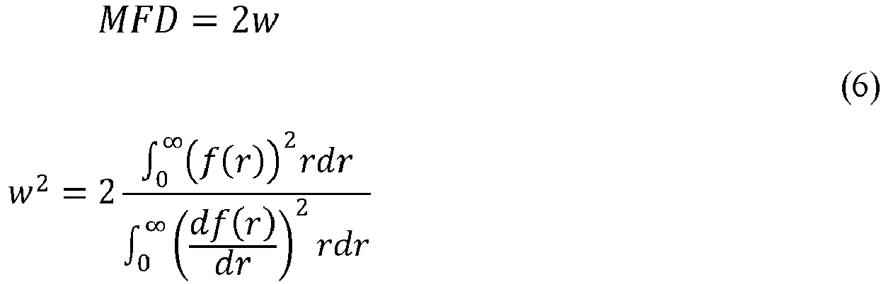
- "Effective area" of an optical fiber is defined in Eq. (7) as:

- The term "attenuation," as used herein, is the loss of optical power as the signal travels along the optical fiber. Attenuation was measured as specified by the IEC-60793-1-40 standard, "Attenuation measurement methods."
- The bend resistance of an optical fiber, expressed as "bend loss" herein, can be gauged by induced attenuation under prescribed test conditions as specified by the IEC-60793-1-47 standard, "Measurement methods and test procedures - Macrobending loss." For example, the test condition can entail deploying or wrapping the fiber one or more turns around a mandrel of a prescribed diameter, e.g., by wrapping 1 turn around either a 15 mm, 20 mm, or 30 mm or similar diameter mandrel (e.g. "1×15 mm diameter bend loss" or the "1×20 mm diameter bend loss" or the "1×30 mm diameter bend loss") and measuring the increase in attenuation per turn.
- "Cable cutoff wavelength," or "cable cutoff," as used herein, refers to the 22 m cable cutoff test as specified by the IEC 60793-1-44 standard, "Measurement methods and test procedures - Cut-off wavelength."
- The optical fibers disclosed herein include a core region, a cladding region surrounding the core region, and a coating surrounding the cladding region. The core region and cladding region are glass. The cladding region includes multiple regions. The multiple cladding regions are preferably concentric regions. The cladding region includes an inner cladding region, a first depressed-index cladding region, an intermediate cladding region, a second depressed-index cladding region, and an outer cladding region. The inner cladding region surrounds and is directly adjacent to the core region. The first depressed-index cladding region surrounds and is directly adjacent to the inner cladding region such that the first depressed-index cladding region is disposed between the inner cladding region and the intermediate cladding region in a radial direction. The intermediate cladding region surrounds and is directly adjacent to the first depressed-index cladding region such that the intermediate cladding region is disposed between the first depressed-index cladding region and the second depressed-index cladding region in a radial direction. The second depressed-index cladding region surrounds and is directly adjacent to the intermediate cladding region such that the second depressed-index cladding region is disposed between the intermediate cladding region and the outer cladding region in a radial direction. The outer cladding region surrounds and is directly adjacent to the second depressed-index cladding region.
- The first and second depressed-index cladding regions each have a lower relative refractive index than the inner cladding region, the intermediate cladding region, and the outer cladding region. The relative refractive index of the inner cladding region may be less than, equal to, or greater than the relative refractive index of the intermediate cladding region and of the outer cladding region.
- The first and second depressed-index claddings region may each be referred to herein as a trench or trench region. The embodiments of the present disclosure also disclose a dual trench design because the refractive index profiles of the optical fibers include both the first and second depressed-index cladding regions. These depressed-index cladding regions contribute to a reduction in bending losses and microbending sensitivity.
- Whenever used herein, radial position r1 and relative refractive index Δ1 or Δ1(r) refer to the core region, radial position r2 and relative refractive index Δ2 or Δ2(r) refer to the inner cladding region, radial position r3 and relative refractive index Δ3 or Δ3(r) refer to the first depressed-index cladding region, radial position r4 and relative refractive index Δ4 or Δ4(r) refer to the intermediate cladding region, radial position r5 and relative refractive index Δ5(r) refer to the second depressed-index cladding region, and radial position r6 and relative refractive index Δ6(r) refer to the outer cladding region. Additionally, a radial position r7 (not shown) refers to a primary coating, radial position r8 (not shown) refers to a secondary coating, and the radial position r9 (not shown) refers to an optional tertiary coating.
- The relative refractive index Δ1(r) has a maximum value Δ1max and a minimum value Δ1min. The relative refractive index Δ2(r) has a maximum value Δ2max and a minimum value Δ2min. The relative refractive index Δ3(r) has a maximum value Δ3max and a minimum value Δ3min. The relative refractive index Δ4(r) has a maximum value Δ4max and a minimum value Δ4min. The relative refractive index Δ5(r) has a maximum value Δ5max and a minimum value Δ5min. The relative refractive index Δ6(r) has a maximum value Δ6max and a minimum value Δ6min. In embodiments in which the relative refractive index is constant or approximately constant over a region, the maximum and minimum values of the relative refractive index are equal or approximately equal. Unless otherwise specified, if a single value is reported for the relative refractive index of a region, the single value corresponds to an average value for the region.
- It is understood that the central core region is substantially cylindrical in shape and that the surrounding inner cladding region, depressed-index cladding regions, intermediate cladding region, outer cladding region, primary coating, and secondary coating are substantially annular in shape. Annular regions are characterized in terms of an inner radius and an outer radius. Radial positions r1, r2, r3, r4, r5, r6, r7, r8, r9, refer herein to the outermost radii of the core region, inner cladding region, first depressed-index cladding region, intermediate cladding region, second depressed-index cladding region, outer cladding region, primary coating, secondary coating, and tertiary coating, respectively. The radius r8 also corresponds to the outer radius of the optical fiber in embodiments without a tertiary coating. When a tertiary coating is present, the radius r9 corresponds to the outer radius of the optical fiber.
- The difference between radial position r2 and radial position r1 is the thickness of the inner cladding region. The difference between radial position r3 and radial position r2 is the thickness of the first depressed-index cladding region. The difference between radial position r4 and radial position r3 is the thickness of the intermediate cladding region. The difference between radial position r5 and radial position r4 is the thickness of the second depressed-index cladding region. The difference between radial position r6 and radial position r5 is the thickness of the outer cladding region. The difference between radial position r7 and radial position r6 is the thickness of the primary coating. The difference between radial position r8 and radial position r7 is the thickness of the secondary coating.
- Reference will now be made in detail to illustrative embodiments of the present description.
- One embodiment relates to an optical fiber. The optical fiber includes a glass fiber surrounded by a coating. An example of an optical fiber is shown in schematic cross-sectional view in
FIG. 1 .Optical fiber 10 includesglass fiber 20 surrounded byprimary coating 50 andsecondary coating 60.Glass fiber 20 includes acore region 30 and acladding region 40. In some embodiments,secondary coating 60 may include a pigment. Further description ofglass fiber 20,primary coating 50, andsecondary coating 60 is provided below. Additionally, one or more tertiary ink layers may surroundsecondary coating 60. -
FIG. 2 illustrates anoptical fiber ribbon 15, which may include a plurality ofoptical fibers 10 and amatrix 70 encapsulating the plurality of optical fibers. As shown inFIG. 2 ,optical fibers 10 are aligned relative to one another in a substantially planar and parallel relationship. The optical fibers infiber optic ribbon 15 are encapsulated by thematrix 70 in any of several known configurations (e.g., edge-bonded ribbon, thin-encapsulated ribbon, thick-encapsulated ribbon, or multi-layer ribbon) by conventional methods of making fiber optic ribbons. Fiberoptic ribbon 15 in the embodiment ofFIG. 2 contains twelve (12)optical fibers 10. However, it is contemplated that any number of optical fibers 10 (e.g., two or more) may be employed to formfiber optic ribbon 70 for a particular use.Matrix 70 has tensile properties similar to the tensile properties of a secondary coating and can be formed from the same, similar, or different composition used to prepare a secondary coating. -
FIG. 3 illustrates anoptical fiber cable 17 that includes a plurality ofoptical fibers 10 surrounded by ajacket 80.Fibers 10 may be densely or loosely packed into a conduit enclosed by aninner surface 85 ofjacket 80. The number of fibers placed injacket 42 is referred to as the "fiber count" ofoptical fiber cable 40. -
Jacket 80 is formed from an extruded polymer material and may include multiple concentric layers of polymers or other materials.Optical fiber cable 17 may include one or more strengthening members (not shown) embedded withinjacket 80 or placed within the conduit defined byinner surface 85. Strengthening members include fibers or rods that are more rigid thanjacket 80. The strengthening member may be made from metal, braided steel, glass-reinforced plastic, fiber glass, or other suitable material.Optical fiber cable 17 may include other layers surrounded byjacket 80 such as, for example, armor layers, moisture barrier layers, rip cords, etc. Furthermore,optical fiber cable 40 may have a stranded, loose tube core or other fiber optic cable construction. - As discussed above with reference to
FIG. 1 ,glass fiber 20 includescore region 30 andcladding region 40.Core region 30 has a higher refractive index than claddingregion 40, andglass fiber 20 functions as a waveguide. In many applications,core region 30 andcladding region 40 have a discernible core-cladding boundary. Alternatively,core region 30 andcladding region 40 can lack a distinct boundary. - A schematic cross-sectional depiction of an
exemplary glass fiber 20 is shown inFIG. 4 . InFIG. 4 ,cladding region 40 includesinner cladding region 42, first depressed-index cladding region 43,intermediate cladding region 44, second depressed-index cladding region 45, andouter cladding region 46. -
FIG. 5 plots an idealized relative refractive index profile ofglass fiber 20 as the relative refractive index Δ versus the radial coordinate r.Core region 30 has relative refractive index Δ1(r), with a maximum refractive index of Δ0 = Δ1MAX at r = 0 and a gradient α-profile, which is described in greater detail below.Inner cladding region 42 has a relative refractive index Δ2 and a width W2. First depressed-index cladding region 43 can be in the form of a depressed region or a trench and has a width W3 and a relative refractive index Δ3, with a minimum value Δ3MIN.Intermediate cladding region 44 has a relative refractive index Δ4 and a width W4. Second depressed-index cladding region 45 can be in the form of a depressed region or a trench and has a width W5 and a relative refractive index Δ5, with a minimum value Δ5MIN.Outer cladding region 46 has a width W6 and relative refractive index Δ6, which is shown by way of example as Δ6 = Δ4 = Δ2. Furthermore, as shown by way of example, Δ3 < Δ2, Δ3 < Δ4, Δ3 < Δ6, and Δ5 < Δ2, Δ5 < Δ4, Δ5 < Δ6. Other configurations for the relative refractive index profile are discussed further below. -
Core region 30 comprises silica glass that is either undoped silica glass, up-doped silica glass, and/or down-doped silica glass. Up-doped silica glass includes silica glass doped with, for example, germanium (e.g., GeO2), phosphorus (e.g., P2O5), aluminum (e.g. Al2O3), chlorine, or an alkali metal oxide (e.g. Na2O, K2O, Li2O, Cs2O, or Rb2O). In some embodiments, the core comprises germania doped glass having a germania concentration between about 5 wt% and about 10 wt%. In embodiments where the core is doped with alkali dopant, the peak concentration of the alkali in the silica glass may range from about 10 ppm to about 500 ppm, or from about 30 ppm to about 400 ppm. In some embodiments, the silica glass ofcore region 30 is free of germanium and/or chlorine; that is the core region comprises silica glass that lacks germanium and/or chlorine. - Down-doped silica glass includes silica glass doped with, for example, fluorine or boron.
- As discussed above, the relative refractive index of
core region 30 ofglass fiber 20 is described by an α-profile with an α value that is in a range of about 7.0 or less, or about 6.0 or less, or about 5.0 or less, or about 4.0 or less, or about 3.0 or less, or about 2.0 or less, or about 1.0 or less. In some other embodiments, the α value is about 8.0 or greater, or about 9.0 or greater, or about 10.0 or greater, or about 11.0 or greater, or about 12.0 or greater, or about 13.0 or greater. In some embodiments, the core α value is less than 100, or less than 50, or less than 20. In some embodiments, the α value is about 2.0, about 2.2, about 2.4, about 3.0, about 3.2, about 4.4, about 10.0, about 12.0, about 12.2, about 12.4, or about 20. - The outer radius r1 of
core region 30 is in a range from about 3.0 microns to about 7.0 microns, or about 3.5 microns to about 6.5 microns, or about 4.0 microns to about 5.0 microns, or about 4.3 microns to about 5.7 microns. In some embodiments, the outer radius r1 is about 4.2 microns, or about 4.3 microns, or about 4.4 microns, or about 4.5 microns, or about 5.3 microns, or about 5.4 microns, or about 5.5 microns, or about 5.6 microns. - The maximum relative refractive index Δ0 or Δ1max of
core region 30 is in a range from about 0.50% or less, or about 0.40% or less, or about 0.39% or less, or about 0.38% or less, or about 0.37% or less, or about 0.36% or less, or about 0.35% or less, or about 0.34% or less, or about 0.33% or less, or about 0.32% or less, or about 0.31% or less, or about 0.30% or less, or about 0.28% or less, or about 0.25% or less. Additionally or alternatively, the maximum relative refractive index Δ0 or Δ1max ofcore region 30 is about 0.10% or greater, or about 0.15% or greater, or about 0.20% or greater, or about 0.25% or greater, or about 0.30% or greater. In some embodiments, the maximum relative refractive index Δ0 or Δ1max is about 0.32%, or about 0.34%, or about 0.35%, or about 0.37%, or about 0.38%. - Although not depicted in
FIG. 5 , in some embodiments, the relative refractive index ofcore region 30 may have a centerline dip such that the maximum refractive index ofcore region 30 and the maximum refractive index of the entireoptical fiber 10 is located a small distance away from the centerline ofcore region 30 rather than at the centerline ofcore region 30, as depicted inFIG. 5 . -
Inner cladding region 42 may be comprised of undoped silica glass. The inner radius ofinner cladding region 42 is r1, as discussed above. The outer radius r2 ofinner cladding region 42 is in a range from about 6.5 microns to about 15.0 microns, or about 7.0 microns to about 14.0 microns, or about 7.5 microns to about 13.5 microns, or about 8.0 microns to about 12.0 microns, or about 9.0 microns to about 11.0 microns. In some embodiments, the outer radius r2 is about 7.2 microns, or about 7.5 microns, or about 8.9 microns, or about 9.1 microns, or about 10.0 microns, or about 10.6 microns, or about 11.5 microns, or about 11.7 microns, or about 14.0 microns. - The relative refractive index Δ2 of
inner cladding region 42 is in a range from about - 0.20% to about 0.20%, or in a range from about -0.15% to about 0.15%, or in a range from about -0.10% to about 0.10%, or in a range from about -0.05% to about 0.05%. In some embodiments, the relative refractive index Δ2 is about 0.0%. The relative refractive index Δ2 is preferably constant or approximately constant. - First depressed-
index cladding region 43 comprises down-doped silica glass. In some embodiments, first depressed-index cladding region 43 is down-doped with fluorine or boron. However, the down-doping of first depressed-index cladding region 43 can also be accomplished by incorporating voids in silica glass. - The inner radius of first depressed-
index cladding region 43 is r2, as discussed above. The outer radius r3 of first depressed-index cladding region 43 is in a range of about 13.0 microns to about 23.0 microns, or about 13.5 microns to about 22.0 microns, or about 14.0 microns to about 21.0 microns, or about 14.5 microns to about 20.0 microns, or about 15.0 microns to about 19.0 microns, or about 15.5 microns to about 18.5 microns. In some embodiments, the outer radius r3 is about 14.2 microns, or about 14.6 microns, or about 15.9 microns, or about 15.6 microns, or about 17.0 microns, or about 17.1 microns, or about 18.0 microns, or about 20.0 microns. - In some embodiments, first depressed-
index cladding region 43 is a depressed-index cladding region that forms a trench design. The trench design may be an offset trench. The relative refractive index Δ3 of first-depressedindex cladding region 43 is in a range from about - 0.10% to about -0.60%, or about -0.15% to about -0.55%, or about -0.20% to about -0.50%, or about -0.25% to about -0.45%, or about -0.30% to about -0.40%. In some embodiments, the relative refractive index Δ3 of first-depressedindex cladding region 43 is about -0.10%, or about -0.20%, or about-0.25%, or about -0.30%, or about -0.45%, or about -0.50%, or about -0.55%. - The transition regions from
inner cladding region 42 to first depressed-index cladding region 43 and from first depressed-index cladding region 43 tointermediate cladding region 44 are shown as step changes inFIG. 5 . However, it is to be understood that a step change is an idealization and that transition regions may not be strictly vertical in practice. Instead, the transition regions may have a slope or curvature. - A "volume" V3 of first depressed-
index cladding 43 region is defined in Eq. (8) as:
- The trench volume V3 of first depressed-
index cladding region 43 may be about 5.0 %Δ-micron2 to about 70.0 %Δ-micron2, or about 30.0 %Δ-micron2 to about 70.0 %Δ-micron2, or about 40.0 %Δ-micron2 to about 60.0 %Δ-micron2, or about 50.0 %Δ-micron2 to about 55.0 %Δ-micron2. In some embodiments, the trench volume V3 is about 5.5 %Δ-micron2, or about 8.7 %Δ-micron2, or about 15.1 %Δ-micron2, or about 20.1 %Δ-micron2, or about 25.7 %Δ-micron2, or about 27.7 %Δ-micron2, or about 50.5 %Δ-micron2, or about 50.8 %Δ-micron2, or about 50.9 %Δ-micron2 or about 51.0 %Δ-micron2, or about 53.1 %Δ-micron2, or about 54.2 %Δ-micron2, or about 56.9 %Δ-micron2, or about 57.0 %Δ-micron2. - A center of mass of the radial position of first depressed-
index cladding region 43 is defined in Eq. (9) as:
- The center of mass of the radial position of first depressed-
index cladding region 43 is in a range between about 6.0 microns and about 20.0 microns, or about 7.0 microns and about 18.0 microns, or about 8.0 microns and about 17.0 microns, or about 10.0 microns and about 15.0 microns, or about 11.0 microns and about 14.0 microns, or about 12.0 microns and about 13.0 microns. In some embodiments, the center of mass of the radial position of first depressed-index cladding region 43 is 11.9 microns, or 12.7 microns, or 13.3 microns. - As also discussed further below, first depressed-
index cladding region 43 may have either a rectangular or triangular profile. -
Intermediate cladding region 44 may be comprised of undoped silica glass. The inner radius ofintermediate cladding region 44 is r3, as discussed above. The outer radius r4 ofintermediate cladding region 44 is in a range from about 15.0 microns to about 26.0 microns, or about 16.0 microns to about 25.0 microns, or about 17.0 microns to about 22.0 microns, or about 18.0 microns to 21.0 microns. In some embodiments, outer radius r4 ofintermediate cladding region 44 is about 17.0 microns, or about 17.5 microns, or about 18.0 microns, or about 18.2 microns, or about 18.5 microns, or about 20.0 microns, or about 20.2 microns, or about 20.5 microns. - The relative refractive index Δ4 of
intermediate cladding region 44 is in a range from about -0.20% to about 0.20%, or in a range from about -0.15% to about 0.15%, or in a range from about -0.10% to about 0.10%, or in a range from about -0.05% to about 0.05%. In some embodiments, the relative refractive index Δ4 is about 0.0%. The relative refractive index Δ4 is preferably constant or approximately constant. Furthermore, is some embodiments, the relative refractive index Δ4 is equal to or substantially equal to the relative refractive index Δ2. - Second depressed-
index cladding region 45 comprises down-doped silica glass. In some embodiments, second depressed-index cladding region 45 is down-doped with fluorine or boron. The down-dopant of second depressed-index cladding region 45 may be the same or different from the down-dopant of first depressed-index cladding region 43. - The inner radius of second depressed-
index cladding region 45 is r4, as discussed above. The outer radius r5 of second depressed-index cladding region 45 is in a range of about 16.0 microns to about 30.0 microns, or about 17.0 microns to about 28.0 microns, or about 18.0 microns to about 26.0 microns, or about 19.0 microns to about 25.0 microns. In some embodiments, the outer radius r4 is about 17.0 microns, or about 17.4 microns, or about 18.0 microns, or about 20.0 microns, or about 24.4 microns or about 24.6 microns, or about 24.8 microns, or about 24.9 microns, or about 25.0 microns, or about 25.3 microns, or about 25.4 microns. - In some embodiments, second depressed-
index cladding region 45 is a depressed-index cladding region that forms a trench design. The trench design may be an offset trench. The relative refractive index Δ5 of second-depressedindex cladding region 45 is in a range from about -0.004% to about -0.350%, or about -0.008% to about -0.300%, or about -0.020% to about -0.250%, or about -0.020% to about -0.200%, or about -0.060% to about -0.200%, or about - 0.080% to about -0.150%, or about -0.100% to about -0.125%. In some embodiments, the relative refractive index Δ5 of second depressed-index cladding region 45 is about -0.020%, or about -0.040%, or about -0.060%, or about -0.072%, or about -0.080%, or about -0.100%, or about -0.1100%, or about -0.120%, or about -0.180%, or about -0.145%, or about -0.200%, or about -0.250%, or about -0.300%. - The transition regions from
intermediate cladding region 44 to second depressed-index cladding region 45 and from second depressed-index cladding region 45 toouter cladding region 46 are shown as step changes inFIG. 5 . However, it is to be understood that a step change is an idealization and that transition regions may not be strictly vertical in practice. Instead, the transition regions may have a slope or curvature. - A "volume" V5 of second depressed-
index cladding region 45 is defined in Eq. (10) as:
where Δ3-6 =(Δ3(r)-Δ6). - The trench volume V5 of second depressed-
index cladding region 45 may be about 0.10 %Δ-micron2 to about 50.0 %Δ-micron2, or from about 0.5 %Δ-micron2 to about 40.0 %Δ-micron2, or from about 1.0 %Δ-micron2 to about 30.0 %Δ-micron2, or from about 5.0 %Δ-micron2 to about 25.0 %Δ-micron2, or from about 8.0 %Δ-micron2 to about 23.0 %Δ-micron2. In some embodiments, the trench volume V5 is about 10.0 %Δ-micron2 or less, or about 8.0 %Δ-micron2 or less, or about 5.0 %Δ-micron2 or less, or about 2.5 %Δ-micron2 or less, or about 2.0 %Δ-micron2 or less, or about 1.0 %Δ-micron2 or less, or about 0.75 %Δ-micron2 or less, or about 0.5 %Δ-micron2 or less, or about 0.25 %Δ-micron2 or less, or about 0.2 %Δ-micron2 or less, or about 0.1 %Δ-micron2 or less. In some exemplary embodiments, , the trench volume V5 is about 7.74 %Δ-micron2, or about 8.22 %Δ-micron2, or about 8.48 %Δ-micron2, or about 11.82 %Δ-micron 2, or about 12.32 %Δ-micron2, or about 12.72 %Δ-micron2, or about 13.83 %Δ-micron2, or about 15.58 %Δ-micron2, or about 16.43 %Δ-micron2, or about 16.96 %Δ-micron2, or about 18.43 %Δ-micron2, or about 19.34 %Δ-micron2, or about 20.54 %Δ-micron2, or about 21.20 %Δ-micron2, or about 21.70 %Δ-micron2, or about 23.04 %Δ-micron2, or about 25.44 %Δ-micron2. - A center of mass of the radial position of second depressed-
index cladding region 45 is defined in Eq. (11) as:
- The center of mass of the radial position of second depressed-
index cladding region 45 is in a range between about 15.0 microns and about 35.0 microns, or about 15.5 microns and about 32.0 microns, or about 16.0 microns and about 30.0 microns, or about 18.0 microns and about 28.0 microns, or about 20.0 microns and about 25.0 microns, or about 21.0 microns and about 24.0 microns, or about 16.0 microns and about 18.0 microns. In some embodiments, the center of mass of the radial position of second depressed-index cladding region 45 is about 22.6 microns, or about 22.9 microns, or about 23.3 microns. - A ratio of the center of mass of the radial position of first depressed-
index cladding region 43 to second depressed-index cladding 45 is in a range from about 0.25 to about 0.75, or about 0.30 to about 0.70, or about 0.35 to about 0.65, or about 0.40 to about 0.60. In some embodiments, the ratio is about 0.52, or about 0.53, or about 0.54, or about 0.56, or about 0.57, or about 0.59. - As also discussed further below, second depressed-
index cladding region 45 may have either a rectangular or triangular profile. -
Outer cladding region 46 may be comprised of undoped silica glass. The inner radius ofouter cladding region 46 is r5, as discussed above. The outer radius r6 ofouter cladding region 46 is in a range from about 40.0 microns to about 65 microns, or from about 45.0 microns to about 62.5 microns, or from about 50.0 microns to about 60.0 microns, or from about 52.5 microns to about 57.5 microns. In some embodiments, the outer radius r6 ofouter cladding region 46 is about 62.5 microns. - The relative refractive index Δ6 of
inner cladding region 42 is in a range from about - 0.20% to about 0.20%, or in a range from about -0.15% to about 0.15%, or in a range from about -0.10% to about 0.10%, or in a range from about -0.05% to about 0.05%. In some embodiments, the relative refractive index Δ6 is about 0.0%. The relative refractive index Δ6 is preferably constant or approximately constant. Furthermore, is some embodiments, the relative refractive index Δ6 is equal to or substantially equal to the relative refractive index Δ2 and/or the relative refractive index Δ4. - As discussed above, first and second depressed-
index cladding regions index cladding regions index cladding regions cladding regions index cladding region 43 and/or second depressed-index cladding region 45 may be such that the refractive index decreases with increasing radial position. Therefore, the trench volume of the triangular trenches increases with increasing radial position. - In some embodiments, the volume V3 of first depressed-
index cladding region 43 is greater than the volume V5 of second depressed-index cladding region 45. For example, a ratio V5/V3 is less than 1.0, or about 0.9 or less, or about 0.8 or less, or about 0.7 or less, or about 0.6 or less, or about 0.5 or less, or about 0.4 or less, or about 0.3 or less, or about 0.2 or less, or about 0.1 or less. In other embodiments, the volume V3 is less than the volume V5. It is also contemplated that the volumes V3 and V5 are equal or substantially equal to each other. - In one embodiment, for example, both first and second depressed-
index cladding regions index cladding region 43 has a triangular profile, second depressed-index cladding region 45 has a rectangular profile, and the ratio V5/V3 is about 0.1, or about 0.2, or about 0.3, or about 0.4. - Without intending to be limited by theory, and as discussed further below, the combination of first and second depressed-
index cladding regions 43, 45 (i.e., dual trench design) provides low bend loss across more bend diameters than conventional fibers. Such reduced bend loss is able to be achieved at a relatively high mode field diameter. Additionally, as also discussed further below, the location of first and second depressed-index cladding regions -
Primary coating 50 immediately surroundsglass fiber 20, andsecondary coating 60 immediately surroundsprimary coating 50. In some embodiments,primary coating 50 comprises a low modulus material andsecond coating 60 comprises a high modulus material. One or more of the materials may be, for example, acrylate. -
Optical fiber 10 may also include a tertiary coating that surroundssecondary coating 60. The tertiary coating may include pigments, inks, or other coloring agents to mark the optical fiber for identification purposes and typically has a Young's modulus similar to the Young's modulus of the secondary coating. - An outer diameter of
secondary coating 60 is an outer diameter ofoptical fiber 10, when a tertiary layer is not applied. The outer diameter ofsecondary coating 60 may be about 250 microns or less, or about 220 microns or less, or about 210 microns or less, or about 200 microns or less, or about 190 microns or less, or about 180 microns or less, or about 170 microns or less. - The optical fibers disclosed herein have good reduced bend sensitivity across all bend diameter (e.g., 15 mm, 20 mm, 30 mm). Thus, the optical fibers disclosed herein meet the G.657 bend loss standards across all these bend diameters. These bend loss standards are achieved while maintaining a high mode field diameter, in contrast to conventional fibers.
- The optical fibers disclosed herein have a bend loss at 1550 nm, as determined by the mandrel wrap test having a diameter of 15 mm, of less than about 0.75 dB/turn, or less than about 0.50 dB/turn, or less than about 0.25 dB/turn, or less than about 0.20 dB/turn, or less than about 0.15 dB/turn, or less than about 0.14 dB/turn, or less than about 0.13 dB/turn, or less than about 0.12 dB/turn, or less than about 0.11 dB/turn, or less than about 0.10 dB/turn, or less than about 0.09 dB/turn, or less than about 0.08 dB/turn, or less than about 0.07 dB/turn, or less than about 0.06 dB/turn, or less than about 0.06 dB/turn.
- Additionally, the optical fibers disclosed herein have a bend loss at 1550 nm, as determined by the mandrel wrap test having a diameter of 20 mm, of less than about 0.20 dB/turn, or less than about 0.15 dB/turn, or less than about 0.10 dB/turn, or less than about 0.08 dB/turn, or less than about 0.06 dB/turn, or less than about 0.05 dB/turn, or less than about 0.04 dB/turn, or less than about 0.03 dB/turn, or less than about 0.02 dB/turn, or less than about 0.01 dB/turn, or less than about 0.009 dB/turn , or less than about 0.008 dB/turn, or less than about 0.007 dB/turn, or less than about 0.006 dB/turn, or less than about 0.005 dB/turn, or less than about 0.004 dB/turn.
- Additionally, the optical fibers disclosed herein have a bend loss at 1550 nm, as determined by the mandrel wrap test having a diameter of 30 mm, of less than about 0.0060 dB/turn, or less than about 0.0050 dB/turn, or less than about 0.0040 dB/turn, or less than about 0.0035 dB/turn, or less than about 0.0030 dB/turn, or less than about 0.0025 dB/turn, or less than about 0.0024 dB/turn, or less than about 0.0023 dB/turn, or less than about 0.0021 dB/turn, or less than about 0.0020 dB/turn, or less than about 0.0019 dB/turn, or less than about 0.0018 dB/turn, or less than about 0.0017 dB/turn, or less than about 0.0016 dB/turn, or less than about 0.0015 dB/turn, or less than about 0.0014 dB/turn, or less than about 0.0013 dB/turn, or less than about 0.0012 dB/turn, or less than about 0.0011 dB/turn, or less than about 0.0010 dB/turn, or less than about 0.0009 dB/turn, or less than about 0.00085 dB/turn, or less than about 0.0008 dB/turn.
- As discussed above, and without intending to be limited by theory, the location and trench volume of first depressed-
index cladding region 43 provides the G.657 compliant bend losses at smaller bend diameters (e.g., < 25 mm) and the location and trench volume of second depressed-index cladding region 45 provides the G.657 compliant bend losses at larger bend diameters (e.g., > 25 mm). It is also noted that the position of the second trench (second depressed-index cladding region 45) is chosen such that it has minimal or zero effect on the cable cutoff and does not negatively impact other optical properties (such as effective area, dispersion, etc.). - In addition to the low bend losses disclosed above, the optical fibers disclosed herein also have a mode field diameter, at 1310 nm wavelength, in range of about 8.9 microns or greater, or about 9.0 microns or greater, or about 9.1 microns or greater, or about 9.2 microns or greater, or about 9.3 microns or greater, or about 9.4 microns or greater, or about 9.5 microns or greater. In some embodiments, the mode field diameter is in a range from about 8.9 microns to about 9.7 microns, or from about 9.0 microns to about 9.6 microns. For example, the mode field diameter is about 9.07 microns, about 9.08 microns, about 9.23 microns, about 9.26 microns, or about 9.27 microns at 1310 nm wavelength.
- The cable cutoff of the optical fibers disclosed herein is about 1300 nm or less, or about 1260 nm or less, or about 1250 nm or less, or about 1240 nm or less, or about 1230 nm or less, or about 1220 nm or less, or about 1210 nm or less, or about 1205 nm or less, or about 1200 nm or less, or about 1195 nm or less, or about 1190 nm or less, or about 1185 nm or less, or about 1180 nm or less, or about 1175 nm or less, or about 1170 nm or less.. For example, the cable cutoff is about 1227 nm, about 1226 nm, about 1222 nm, about 1220 nm, about 1218 nm, about 1216 nm, about 1215 nm, about 1205 nm, about 1203 nm, about 1200 nm, about 1180 nm, or about 1176 nm.
- Furthermore, the optical fibers disclosed herein have an effective area, at 1310 nm wavelength, of about 70.0 micron2 or less, or about 69.0 micron2 or less, or about 68.0 micron2 or less, or about 67.0 micron2 or less, or about 66.0 micron2 or less, or about 65.0 micron2 or less, or about 64.0 micron2 or less, or about 63.0 micron2 or less, or about 62.0 micron2 or less, or about 61.0 micron2 or less, or about 60.0 micron2 or less. The optical fibers also have an effective area, at 1550 nm wavelength, of about 75 micron2 or greater, or about 78 micron2 or greater, or about 80 micron2 or greater. Additionally or alternatively, the effective area, at 1550 nm wavelength, is about 95 micron2 or less, or about 90 micron2 or less, or about 85 micron2 or less. In some embodiments, the effective area, at 1550 nm wavelength, is in range between 75 micron2 and about 90 micron2.
- The optical fibers disclosed herein also have zero dispersion wavelength from about 1290 nm to about 1330 nm. For example, the zero dispersion wavelength can be from about 1295 nm to about 1325 nm, about 1300 nm to about 1324 nm, or from about 1305 nm to about 1315 nm. For example, the zero dispersion wavelength can be about 1280 nm, about 1285 nm, about 1289 nm, about 1290 nm, about 1300 nm, about 1301 nm, about 1305 nm, about 1306 nm, about 1310 nm, about 1315 nm, or about 1320 nm.
- Additionally, the attenuation of the optical fibers disclosed herein is less than or equal to about 0.35 dB/km at 1310 nm wavelength, less than or equal to about 0.2 dB/km at 1550 nm wavelength, and less than or equal to about 0.35 dB/turn at 1625 nm wavelength. In some embodiments, the attenuation is less than or equal to about 0.19 dB/turn, or less than or equal to about 0.18 dB/turn, or less than or equal to about 0.185 dB/turn at 1550 nm wavelength.
- According to an aspect of the present disclosure, the optical fibers have a dispersion having an absolute value at 1310 nm in a range between about -3 ps/nm/km and about 3 ps/nm/km and a dispersion slope at 1310 nm in a range between about 0.085 ps/nm2/km and 0.095 ps/nm2/km. For example, the absolute value of the dispersion at 1310 nm can be from about 2 ps/nm/km to about 2 ps/nm/km,, about 1.5 ps/nm/km to about 1.5 ps/nm/km, about 1.5 ps/nm/km to about 1 ps/nm/km. For example, the absolute value of the dispersion at 1310 can be about 1.2 ps/nm/km, about 0.1 ps/nm/km, about 0.7 ps/nm/km, about 0.4 ps/nm/km, about 0.2 ps/nm/km, about 0.0 ps/nm/km, about 0.2 ps/nm/km, about 0.4 ps/nm/km, about 0.6 ps/nm/km, about 0.8 ps/nm/km, about 0.9 ps/nm/km, or any value between these values. In one example, the dispersion slope at 1310 nm can be about 0.07 ps/nm2/km to about 0.1 ps/nm2/km, about 0.08 ps/nm2/km to about 0.1 ps/nm2/km, about 0.085 ps/nm2/km to about 0.1 ps/nm2/km, about 0.09 ps/nm2/km to about 0.1 ps/nm2/km, about 0.075 ps/nm2/km to about 0.09 ps/nm2/km, about 0.08 ps/nm2/km to about 0.09 ps/nm2/km, or about 0.085 ps/nm2/km to about 0.09 ps/nm2/km. For example, the dispersion slope at 1310 nm can be about 0.075 ps/nm2/km, about 0.08 ps/nm2/km, about 0.085 ps/nm2/km, about 0.086 ps/nm2/km, about 0.087 ps/nm2/km, about 0.088 ps/nm2/km, about 0.089 ps/nm2/km, about 0.09 ps/nm2/km, or about 0.01 ps/nm2/km.
- According to an aspect of the present disclosure, the optical fibers have a dispersion at 1550 nm of less than 22 ps/nm/km and a dispersion slope at 1550 nm of less than 0.1 ps/nm2/km. For example, the dispersion at 1550 nm can be from about 10 ps/nm/km to about 22 ps/nm/km, about 10 ps/nm/km to about 22 ps/nm/km, about 10 ps/nm/km to about 20 ps/nm/km, about 10 ps/nm/km to about 15 ps/nm/km, about 15 ps/nm/km to about 22 ps/nm/km, or about 15 ps/nm/km to about 20 ps/nm/km. For example, the dispersion at 1550 can be about 10 ps/nm/km, about 15 ps/nm/km, about 16 ps/nm/km, about 17 ps/nm/km, about 17.5 ps/nm/km, about 18 ps/nm/km, about 19 ps/nm/km, about 19.5 ps/nm/km, about 19.6 ps/nm/km, about 20 ps/nm/km, about 20.1 ps/nm/km, about 22 ps/nm/km, or any value between these values. In one example, the dispersion slope at 1550 nm can be about 0.04 ps/nm2/km to about 0.1 ps/nm2/km, about 0.05 ps/nm2/km to about 0.1 ps/nm2/km, about 0.055 ps/nm2/km to about 0.1 ps/nm2/km, about 0.06 ps/nm2/km to about 0.1 ps/nm2/km, about 0.08 ps/nm2/km to about 0.1 ps/nm2/km, about 0.04 ps/nm2/km to about 0.08 ps/nm2/km, about 0.05 ps/nm2/km to about 0.08 ps/nm2/km, about 0.055 ps/nm2/km to about 0.08 ps/nm2/km, about 0.06 ps/nm2/km to about 0.08 ps/nm2/km, about 0.04 ps/nm2/km to about 0.06 ps/nm2/km, about 0.05 ps/nm2/km to about 0.06 ps/nm2/km, or about 0.055 ps/nm2/km to about 0.06 ps/nm2/km. For example, the dispersion slope at 1550 nm can be about 0.04 ps/nm2/km, about 0.05 ps/nm2/km, about 0.055 ps/nm2/km, about 0.057 ps/nm2/km, about 0.058 ps/nm2/km, about 0.059 ps/nm2/km, about 0.06 ps/nm2/km, about 0.061 ps/nm2/km, about 0.07 ps/nm2/km, or about 0.08 ps/nm2/km.
- Provided below are exemplary embodiments of the optical fibers disclosed herein. The below examples are intended to be exemplary, and are not intended to limit the scope of the disclosure. The exemplary embodiments shown below have a dual trench design with a mode field diameter at 1310 nm of 9 microns or greater, a cable cutoff of less than or equal to 1260 nm, and zero dispersion wavelength between 1300 nm and 1324 nm.
- Table 1 below provides four exemplary embodiments (Ex 1-4) and a comparative example (C1). Exemplary embodiments Ex 1-4 are shown in
FIGS. 6-9 . Exemplary embodiments Ex 1-4 all have a dual trench design with two rectangular shaped depressed-index cladding regions, a peak core refractive index (Δ1max) of 0.336%, and a core alpha of 12. Although comparative example C1, which only has a single depressed-index cladding region, has the same mode field diameter of exemplary embodiments Ex 1-4, comparative example C1 does not meet the G.657 standards across all bend diameters. More specifically, comparative example C1 does not meet the 30 mm bend loss standard.Table 1 C1 Ex1 Ex2 Ex3 Ex4 Maximum Core Index, Δ1max (%) 0.336 0.336 0.336 0.336 0.336 Core Radius, r1, microns 4.2 4.2 4.2 4.2 4.2 Core alpha 12 12 12 12 12 Inner Cladding Index, Δ2 (%) 0 0 0 0 0 Inner Cladding Radius, r2 (microns) 9.14 9.14 9.14 9.14 9.14 First Depressed-Index Cladding Shape Rectangular Rectangular Rectangular Rectangular Rectangular First Depressed-Index Cladding Minimum Index, Δ3,min (%) -0.45 -0.45 -0.45 -0.45 -0.45 First Depressed-Index Cladding Outer Radius, r3 (micron) 14.2 14.2 14.2 14.2 14.2 Volume of First Depressed -Index Cladding Region, V3, %Δ micron 2 -53.14 -53.14 -53.14 -53.14 -53.14 Intermediate Cladding Index, Δ4 (%) 0 0 0 0 0 Intermediate Cladding Radius, r4 (microns) NA 20.24 20.24 20.24 20.24 Second Depressed-Index Cladding Shape NA Rectangular Rectangular Rectangular Rectangular Second Depressed-Index Cladding Minimum Index, Δ5,min (%) NA -0.04 -0.06 -0.08 -0.1 Second Depressed-Index Cladding Outer Radius, r5 (micron) NA 24.8 24.8 24.8 24.8 Volume of Second Depressed -Index Cladding Region, V5, %Δ micron2 0 -8.22 -12.32 -16.43 -20.54 Outer Cladding Index, Δ6 (%) 0 0 0 0 0 Outer Cladding Radius, r6, microns 62.5 62.5 62.5 62.5 62.5 Ratio of V5/V3 0 0.155 0.232 0.309 0.387 Center of Mass Radial Position of First Depressed -Index Cladding Region (microns) 11.85 11.85 11.85 11.85 11.85 Center of Mass Radial Position of Second Depressed -Index Cladding Region (microns) NA 22.60 22.60 22.60 22.60 Ratio of Center of Mass Radial Position of First and Second Depressed -Index Regions NA 0.525 0.525 0.525 0.525 Mode Field Diameter (micron) at 1310 nm 9.07 9.07 9.07 9.07 9.07 Effective Area at 1310 nm (micron2) 64.5 64.5 64.5 64.5 64.5 Zero Dispersion Wavelength (nm) 1310 1310 1309 1309 1309 Dispersion at 1310 nm (ps/nm/km) 0 0 0.069 0.07 0.073 Dispersion Slope at 1310 nm (ps/nm2/km) 0.092 0.077 0.069 0.07 0.073 Mode Field Diameter (micron) at 1550 nm 10.14 10.14 10.14 10.14 10.14 Effective Area at 1550 nm (micron2) 79.16 79.16 79.15 79.15 79.16 Dispersion at 1550 nm (ps/nm/km) 19.03 19.02 19.03 19.03 19.03 Dispersion Slope at 1550 nm (ps/nm2/km) 0.066 0.064 0.064 0.064 0.064 Cable Cutoff (nm) 1215 1216 1218 1220 1222 Bend Loss for 15 mm mandrel diameter at 1550 nm (dB/turn) 0.118 0.134 0.149 0.154 0.141 Bend Loss for 20 mm mandrel diameter at 1550 nm (dB/turn) 0.04 0.065 0.043 0.028 0.018 Bend Loss for 30 mm mandrel diameter at 1550 nm (dB/turn) 0.0063 0.0029 0.0021 0.0016 0.0011 - Table 2 below provides three exemplary embodiments (Ex 5-7), which are also shown in
FIGS. 10-12 . Exemplary embodiments Ex 5-7 all have a dual trench design with two rectangular shaped depressed-index cladding regions, a peak core refractive index (Δ1max) of 0.317%, and a core alpha of 12.Table 2 Ex 5 Ex6 Ex7 Maximum Core Index, Δ1max (%) 0.317 0.317 0.317 Core Radius, r1, microns 4.2 4.2 4.2 Core alpha 12 12 12 Inner Cladding Index, Δ2 (%) 0 0 0 Inner Cladding Radius, r2 (microns) 9.14 9.14 9.14 First Depressed-Index Cladding Shape Rectangular Rectangular Rectangular First Depressed-Index Cladding Minimum Index, Δ3,min (%) -0.45 -0.45 -0.45 First Depressed-Index Cladding Outer Radius, r3 (micron) 14.2 14.2 14.2 Volume of First Depressed-Index Cladding Region, V3, %Δ micron2 -53.14 -53.14 -53.14 Intermediate Cladding Index, Δ4 (%) 0 0 0 Intermediate Cladding Radius, r4 (microns) 20.24 20.24 20.24 Second Depressed-Index Cladding Shape Rectangular Rectangular Rectangular Second Depressed-Index Cladding Minimum Index, Δ5,min (%) -0.06 -0.08 -0.1 Second Depressed-Index Cladding Outer Radius, r5 (micron) 25.3 25.3 25.3 Volume of Second Depressed-Index Cladding Region, V5, %Δ micron2 -13.83 -18.43 -23.04 Outer Cladding Index, Δ6 (%) 0 0 0 Outer Cladding Radius, r6, microns 62.5 62.5 62.5 Ratio of V5/V3 0.260 0.347 0.434 Center of Mass Radial Position of First Depressed-Index Cladding Region (microns) 11.85 11.85 11.85 Center of Mass Radial Position of Second Depressed-Index Cladding Region (microns) 22.86 22.86 22.86 Ratio of Center of Mass Radial Position of First and Second Depressed-Index Regions 0.518 0.518 0.518 Mode Field Diameter (micron) at 1310 nm 9.23 9.23 9.23 Effective Area at 1310 nm (micron2) 66.63 66.6 66.6 Zero Dispersion Wavelength (nm) 1308 1307 1305 Dispersion at 1310 nm (ps/nm/km) 0.1392 0.1899 0.27 Dispersion Slope at 1310 nm (ps/nm2/km) 0.0696 0.0633 0.054 Mode Field Diameter (micron) at 1550 nm 10.32 10.32 10.32 Effective Area at 1550 nm (micron2) 81.97 81.97 81.97 Dispersion at 1550 nm (ps/nm/km) 19.2 19.2 19.19 Dispersion Slope at 1550 nm (ps/nm2/km) 0.064 0.064 0.064 Cable Cutoff (nm) 1176 1180 1181 Bend Loss for 15 mm mandrel diameter at 1550 nm (dB/turn) 0.2078 0.2145 0.213 Bend Loss for 20 mm mandrel diameter at 1550 nm (dB/turn) 0.0878 0.0626 0.04 Bend Loss for 30 mm mandrel diameter at 1550 nm (dB/turn) 0.0034 0.0023 0.0016 - Table 3 below provides four exemplary embodiments (Ex 8-11), which are also shown in
FIGS. 13-16 . Exemplary embodiments Ex 8-11 all have a dual trench design with both a triangular and a rectangular shaped depressed-index cladding region, a peak core refractive index (Δ1max of 0.336%, and a core alpha of 12.Table 3 Ex8 Ex9 Ex10 Ex11 Maximum Core Index, Δ1max (%) 0.336 0.336 0.336 0.336 Core Radius, r1, microns 4.2 4.2 4.2 4.2 Core alpha 12 12 12 12 Inner Cladding Index, Δ2 (%) 0 0 0 0 Inner Cladding Radius, r2 (microns) 7.16 7.16 7.16 7.16 First Depressed-Index Cladding Shape Triangular Triangular Triangular Triangular First Depressed-Index Cladding Minimum Index, Δ3,min (%) -0.5 -0.5 -0.5 -0.5 First Depressed-Index Cladding Outer Radius, r3 (micron) 15.9 15.9 15.9 15.9 Volume of First Depressed-Index Cladding Region, V3, %Δ micron2 -56.9 -56.9 -56.9 -56.9 Intermediate Cladding Index, Δ4 (%) 0 0 0 0 Intermediate Cladding Radius, r4 (microns) 20.24 20.24 20.24 20.24 Second Depressed-Index Cladding Shape Rectangular Rectangular Rectangular Rectangular Second Depressed-Index Cladding Minimum Index, Δ5,min (%) -0.04 -0.06 -0.08 -0.1 Second Depressed-Index Cladding Outer Radius, r5 (micron) 24.8 24.8 24.8 24.8 Volume of Second Depressed-Index Cladding Region, V5, %Δ micron2 -8.22 -12.32 -16.43 -20.54 Outer Cladding Index, Δ6 (%) 0 0 0 0 Outer Cladding Radius, r6, microns 62.5 62.5 62.5 62.5 Ratio of V5/V3 0.144 0.217 0.289 0.361 Center of Mass Radial Position of First Depressed-Index Cladding Region (microns) 13.32 13.32 13.32 13.32 Center of Mass Radial Position of Second Depressed-Index Cladding Region (microns) 22.60 22.60 22.60 22.60 Ratio of Center of Mass Radial Position of First and Second Depressed-Index Regions 0.59 0.59 0.59 0.59 Mode Field Diameter (micron) at 1310 nm 9.08 9.08 9.08 9.08 Effective Area at 1310 nm (micron2) 64.5 64.5 64.5 64.5 Zero Dispersion Wavelength (nm) 1314 1314 1314 1314 Dispersion at 1310 nm (ps/nm/km) -0.332 -0.344 -0.332 -0.336 Dispersion Slope at 1310 nm (ps/nm2/km) 0.083 0.086 0.083 0.084 Mode Field Diameter (micron) at 1550 nm 10.21 10.21 10.21 10.21 Effective Area at 1550 nm (micron2) 79.78 79.78 79.78 79.78 Dispersion at 1550 nm (ps/nm/km) 18.32 18.32 18.32 18.32 Dispersion Slope at 1550 nm (ps/nm2/km) 0.064 0.064 0.064 0.064 Cable Cutoff (nm) 1226 1226 1227 1227 Bend Loss for 15 mm mandrel diameter at 1550 nm (dB/turn) 0.089 0.093 0.088 0.074 Bend Loss for 20 mm mandrel diameter at 1550 nm (dB/turn) 0.042 0.027 0.018 0.012 Bend Loss for 30 mm mandrel diameter at 1550 nm (dB/turn) 0.0023 0.0017 0.0012 0.00095 - Table 4 below provides four exemplary embodiments (Ex 12-15), which are also shown in
FIGS. 17-20 . Exemplary embodiments Ex 12-15 all have a dual trench design with two triangular shaped depressed-index cladding regions, a peak core refractive index (Δ1max) of 0.336%, and a core alpha of 12.Table 4 Ex12 Ex13 Ex14 Ex15 Maximum Core Index, Δ1max (%) 0.336 0.336 0.336 0.336 Core Radius, r1, microns 4.2 4.2 4.2 4.2 Core alpha 12 12 12 12 Inner Cladding Index, Δ2 (%) 0 0 0 0 Inner Cladding Radius, r2 (microns) 7.16 7.16 7.16 7.16 First Depressed-Index Cladding Shape Triangular Triangular Triangular Triangular First Depressed-Index Cladding Minimum Index, Δ3,min (%) -0.5 -0.5 -0.5 -0.5 First Depressed-Index Cladding Outer Radius, r3 (micron) 15.9 15.9 15.9 15.9 Volume of First Depressed-Index Cladding Region, V3, %Δ micron2 -56.9 -56.9 -56.9 -56.9 Intermediate Cladding Index, Δ4 (%) 0 0 0 0 Intermediate Cladding Radius, r4 (microns) 20.2 20.2 20.2 20.2 Second Depressed-Index Cladding Shape Triangular Triangular Triangular Triangular Second Depressed-Index Cladding Minimum Index, Δ5,min (%) -0.072 -0.11 -0.145 -0.18 Second Depressed-Index Cladding Outer Radius, r5 (micron) 24.8 24.8 24.8 24.8 Volume of Second Depressed-Index Cladding Region, V5, %Δ micron 2 -7.74 -11.82 -15.58 -19.34 Outer Cladding Index, Δ6 (%) 0 0 0 0 Outer Cladding Radius, r6, microns 62.5 62.5 62.5 62.5 Ratio of V5/V3 0.136 0.208 0.274 0.340 Center of Mass Radial Position of First Depressed-Index Cladding Region (microns) 13.32 13.32 13.32 13.32 Center of Mass Radial Position of Second Depressed-Index Cladding Region (microns) 23.32 23.32 23.32 23.32 Ratio of Center of Mass Radial Position of First and Second Depressed-Index Regions 0.57 0.57 0.57 0.57 Mode Field Diameter (micron) at 1310 nm 9.08 9.08 9.08 9.08 Effective Area at 1310 nm (micron2) 64.5 64.5 64.5 64.5 Zero Dispersion Wavelength (nm) 1314 1314 1314 1314 Dispersion at 1310 nm (ps/nm/km) -0.344 -0.332 -0.324 -0.34 Dispersion Slope at 1310 nm (ps/nm2/km) 0.086 0.083 0.081 0.085 Mode Field Diameter (micron) at 1550 nm 10.21 10.21 10.21 10.21 Effective Area at 1550 nm (micron2) 79.78 79.78 79.78 79.78 Dispersion at 1550 nm (ps/nm/km) 18.32 18.32 18.32 18.32 Dispersion Slope at 1550 nm (ps/nm2/km) 0.064 0.064 0.064 0.064 Cable Cutoff (nm) 1226 1226 1227 1228 Bend Loss for 15 mm mandrel diameter at 1550 nm (dB/turn) 0.11 0.118 0.1254 0.117 Bend Loss for 20 mm mandrel diameter at 1550 nm (dB/turn) 0.048 0.031 0.021 0.015 Bend Loss for 30 mm mandrel diameter at 1550 nm (dB/turn) 0.0024 0.0018 0.0014 0.001 - Table 5 below provides five exemplary embodiments (Ex 16-20) and a comparative example (C2). Exemplary embodiments Ex 16-20 are shown in
FIGS. 21-25 . Exemplary embodiments Ex 16-20 all have a dual trench design with two rectangular shaped depressed-index cladding regions, a peak core refractive index (Δ1max) of 0.37%, and a core alpha of 2.2. Although comparative example C2, which only has a single depressed-index cladding region, has a similar mode field diameter of exemplary embodiments Ex 16-20, comparative example C2 does not meet the G.657 standards across all bend diameters. More specifically, comparative example C2 does not meet the 30 mm bend loss standards.Table 5 C2 Ex16 Ex17 Ex18 Ex19 Ex20 Maximum Core Index, Δ1max (%) 0.37 0.37 0.37 0.37 0.37 0.37 Core Radius, r1, microns 5.3 5.3 5.3 5.3 5.3 5.3 Core alpha 2.2 2.2 2.2 2.2 2.2 2.2 Inner Cladding Index, Δ2 (%) 0 0 0 0 0 0 Inner Cladding Radius, r2 (microns) 10.56 10.56 10.56 10.56 10.56 10.56 First Depressed-Index Cladding Shape Rectangular Rectangular Rectangular Rectangular Rectangular Rectangular First Depressed-Index Cladding Minimum Index, Δ3,min (%) -0.5 -0.5 -0.5 -0.5 -0.5 -0.5 First Depressed-Index Cladding Outer Radius, r3 (micron) 14.6 14.6 14.6 14.6 14.6 14.6 Volume of First Depressed -Index Cladding Region, V3, %Δ micron2 -50.82 -50.82 -50.82 -50.82 -50.82 -50.82 Intermediate Cladding Index, Δ4 (%) 0 0 0 0 0 0 Intermediate Cladding Radius, r4 (microns) NA 20.2 20.2 20.2 20.2 20.2 Second Depressed -Index Cladding Shape NA Rectangular Rectangular Rectangular Rectangular Rectangular Second Depressed -Index Cladding Minimum Index, Δ5,min (%) NA -0.04 -0.06 -0.08 -0.1 -0.12 Second Depressed -Index Cladding Outer Radius, r5 (micron) NA 24.9 24.9 24.9 24.9 24.9 Volume of Second Depressed -Index Cladding Region, V5, %Δ micron2 0 -8.48 -12.72 -16.96 -21.20 -25.44 Outer Cladding Index, Δ6 (%) 0 0 0 0 0 0 Outer Cladding Radius, r6, microns 62.5 62.5 62.5 62.5 62.5 62.5 Ratio of V5/V3 0.000 0.167 0.250 0.334 0.417 0.501 Center of Mass Radial Position of First Depressed-Index Cladding Region (microns) 12.69 12.69 12.69 12.69 12.69 12.69 Center of Mass Radial Position of Second Depressed -Index Cladding Region (microns) NA 22.63 22.63 22.63 22.63 22.63 Ratio of Center of Mass Radial Position of First and Second Depressed -Index Regions NA 0.56 0.56 0.56 0.56 0.56 Mode Field Diameter (micron) at 1310 nm 9.26 9.27 9.27 9.27 9.27 9.27 Effective Area at 1310 nm (micron2) 65.29 65.36 65.36 65.36 65.36 65.36 Zero Dispersion Wavelength (nm) 1318 1318 1318 1318 1318 1318 Dispersion at 1310 nm (ps/nm/km) -0.736 -0.68 -0.656 -0.664 -0.632 -0.624 Dispersion Slope at 1310 nm (ps/nm2/km) 0.092 0.085 0.082 0.083 0.079 0.078 Mode Field Diameter (micron) at 1550 nm 10.45 10.46 10.46 10.46 10.46 10.46 Effective Area at 1550 nm (micron2) 82.43 82.48 82.48 82.48 82.48 82.48 Dispersion at 1550 nm (ps/nm/km) 18.35 18.38 18.38 18.38 18.38 18.38 Dispersion Slope at 1550 nm (ps/nm2/km) 0.066 0.065 0.065 0.065 0.065 0.065 Cable Cutoff (nm) 1200 1201 1202 1202 1203 1203 Bend Loss for 15 mm mandrel diameter at 1550 nm (dB/turn) 0.138 0.187 0.168 0.1245 0.084 0.0558 Bend Loss for 20 mm mandrel diameter at 1550 nm (dB/turn) 0.082 0.025 0.0152 0.0098 0.0066 0.0047 Bend Loss for 30 mm mandrel diameter at 1550 nm (dB/turn) 0.012 0.0055 0.0039 0.0028 0.002 0.0016 - Table 6 below provides four exemplary embodiments (Ex 21-24) and a comparative example (C3). Exemplary embodiments Ex 21-24 are shown in
FIGS. 26-29 . Exemplary embodiments Ex 21-24 all have a dual trench design with both rectangular and triangular shaped depressed-index cladding regions, a peak core refractive index (Δ1max) of 0.37%, and a core alpha of 2.2. Although comparative example C3, which only has a single depressed-index cladding region, has the same mode field diameter of exemplary embodiments Ex 21-24, comparative example C3 does not meet the G.657 standards across all bend diameters. More specifically, comparative example C3 does not meet the 30 mm bend loss standards.Table 6 C3 Ex21 Ex22 Ex23 Ex24 Maximum Core Index, Δ1max (%) 0.37 0.37 0.37 0.37 0.37 Core Radius, r1, microns 5.3 5.3 5.3 5.3 5.3 Core alpha 2.2 2.2 2.2 2.2 2.2 Inner Cladding Index, Δ2 (%) 0 0 0 0 0 Inner Cladding Radius, r2 (microns) 7.45 7.45 7.45 7.45 7.45 First Depressed-Index Cladding Shape Triangular Triangular Triangular Triangular Triangular First Depressed-Index Cladding Minimum Index, Δ3,min (%) -0.55 -0.55 -0.55 -0.55 -0.55 First Depressed-Index Cladding Outer Radius, r3 (micron) 14.9 14.9 14.9 14.9 14.9 Volume of First Depressed -Index Cladding Region, V3, %Δ micron2 -50.94 -50.94 -50.94 -50.94 -50.94 Intermediate Cladding Index, Δ4 (%) 0 0 0 0 0 Intermediate Cladding Radius, r4 (microns) NA 20.2 20.2 20.2 20.2 Second Depressed-Index Cladding Shape NA Rectangular Rectangular Rectangular Rectangular Second Depressed-Index Cladding NA -0.04 -0.06 -0.08 -0.1 Minimum Index, Δ5 (%) Second Depressed-Index Cladding Outer Radius, r5 (micron) NA 24.9 24.9 24.9 24.9 Volume of Second Depressed -Index Cladding Region, V5, %Δ micron 2 0 -8.48 -12.72 -16.96 -21.20 Outer Cladding Index, Δ6 (%) 0 0 0 0 0 Outer Cladding Radius, r6, microns 62.5 62.5 62.5 62.5 62.5 Ratio of V5/V3 0.000 0.166 0.250 0.333 0.416 Center of Mass Radial Position of First Depressed -Index Cladding Region (microns) 12.67 12.67 12.67 12.67 12.67 Center of Mass Radial Position of Second Depressed -Index Cladding Region (microns) NA 22.63 22.63 22.63 22.63 Ratio of Center of Mass Radial Position of First and Second Depressed -Index Regions NA 0.56 0.56 0.56 0.56 Mode Field Diameter (micron) at 1310 nm 9.06 9.06 9.06 9.06 9.06 Effective Area at 1310 nm (micron2) 62.4 62.4 62.4 62.4 62.4 Zero Dispersion Wavelength (nm) 1319 1319 1319 1319 1319 Dispersion at 1310 nm (ps/nm/km) -0.837 -0.837 -0.828 -0.837 -0.837 Dispersion Slope at 1310 nm (ps/nm2/km) 0.093 0.093 0.092 0.093 0.093 Mode Field Diameter (micron) at 1550 nm 10.22 10.22 10.22 10.22 10.22 Effective Area at 1550 nm (micron2) 78.69 78.67 78.67 78.67 78.67 Dispersion at 1550 nm (ps/nm/km) 18.27 18.26 18.26 18.26 18.26 Dispersion Slope at 1550 nm (ps/nm2/km) 0.065 0.065 0.065 0.065 0.065 Cable Cutoff (nm) 1204 1204 1205 1205 1205 Bend Loss for 15 mm mandrel diameter at 1550 nm (dB/turn) 0.123 0.1514 0.165 0.162 0.1375 Bend Loss for 20 mm mandrel diameter at 1550 nm (dB/turn) 0.113 0.0665 0.042 0.0267 0.0176 Bend Loss for 30 mm mandrel diameter at 1550 nm (dB/turn) 0.007 0.0033 0.0024 0.0018 0.0014 - Table 7 below provides four exemplary embodiments (Ex 25-28), which are also shown in
FIGS. 30-33 . Exemplary embodiments Ex 25-28 all have a dual trench design with triangular shaped depressed-index cladding regions, a peak core refractive index (Δ1max) of 0.37%, and a core alpha of 2.2.Table 7 Ex25 Ex26 Ex27 Ex28 Maximum Core Index, 0 Δ1max (%) 0.37 0.37 0.37 0.37 Core Radius, r1, microns 5.3 5.3 5.3 5.3 Core alpha 2.2 2.2 2.2 2.2 Inner Cladding Index, Δ2 (%) 0 0 0 0 Inner Cladding Radius, r2 (microns) 7.45 7.45 7.45 7.45 First Depressed-Index Cladding Shape Triangular Triangular Triangular Triangular First Depressed-Index Cladding Minimum Index, Δ3,min (%) -0.55 -0.55 -0.55 -0.55 First Depressed-Index Cladding Outer Radius, r3 (micron) 14.9 14.9 14.9 14.9 Volume of First Depressed-Index Cladding Region, V3, %Δ micron2 -50.94 -50.94 -50.94 -50.94 Intermediate Cladding Index, Δ4 (%) 0 0 0 0 Intermediate Cladding Radius, r4 (microns) 20.2 20.2 20.2 20.2 Second Depressed-Index Cladding Shape Triangular Triangular Triangular Triangular Second Depressed-Index Cladding Minimum Index, Δ5,min (%) -0.072 -0.11 -0.145 -0.18 Second Depressed-Index Cladding Outer Radius, r5 (micron) 24.9 24.9 24.9 24.9 Volume of Second Depressed - Index Cladding Region, V5, %Δ micron2 -7.74 -11.82 -15.58 -19.34 Outer Cladding Index, Δ6 (%) 0 0 0 0 Outer Cladding Radius, r6, microns 62.5 62.5 62.5 62.5 Ratio of V5/V3 0.152 0.232 0.306 0.380 Center of Mass Radial Position of First Depressed-Index Cladding Region (microns) 12.67 12.67 12.67 12.67 Center of Mass Radial Position of Second Depressed-Index Cladding Region (microns) 23.32 23.32 23.32 23.32 Ratio of Center of Mass Radial Position of First and Second Depressed-Index Regions 0.543 0.543 0.543 0.543 Mode Field Diameter (micron) at 1310 nm 9.06 9.06 9.06 9.06 Effective Area at 1310 nm (micron2) 62.4 62.4 62.4 62.4 Zero Dispersion Wavelength (nm) 1319 1319 1319 1319 Dispersion at 1310 nm (ps/nm/km) -0.837 -0.837 -0.837 -0.837 Dispersion Slope at 1310 nm (ps/nm2/km) 0.093 0.093 0.093 0.093 Mode Field Diameter (micron) at 1550 nm 10.22 10.22 10.22 10.22 Effective Area at 1550 nm (micron2) 78.67 78.67 78.67 78.67 Dispersion at 1550 nm (ps/nm/km) 18.26 18.26 18.26 18.26 Dispersion Slope at 1550 nm (ps/nm2/km) 0.065 0.065 0.065 0.065 Cable Cutoff (nm) 1204 1204 1204 1204 Bend Loss for 15 mm mandrel diameter at 1550 nm (dB/turn) 0.166 0.202 0.228 0.2268 Bend Loss for 20 mm mandrel diameter at 1550 nm (dB/turn) 0.079 0.051 0.034 0.0236 Bend Loss for 30 mm mandrel diameter at 1550 nm (dB/turn) 0.0036 0.0027 0.0021 0.0016 - Table 8 below provides five additional exemplary embodiments (Ex 29-33), which are also shown in
FIGS. 34-38 . Exemplary embodiments Ex 29-33 all have a dual trench design with triangular and/or rectangular depressed-index cladding regions.Table 8 Ex29 Ex30 Ex31 Ex32 Ex33 Maximum Core Index, Δ1max (%) 0.352 0.352 0.352 0.352 0.38 Core Radius, r1, microns 4.425 4.425 4.5 4.5 5.6 Core alpha 20 20 20 20 2.2 Inner Cladding Index, Δ2 (%) 0 0 0 0 0 Inner Cladding 10 10 11.5 11.7 8.9 Radius, r2 (microns) First Depressed-Index Cladding Shape Triangular Triangular Rectangular Rectangular Rectangular First Depressed-Index Cladding Minimum Index, Δ3,min (%) -0.4 -0.3 -0.3 -0.1 -0.1 First Depressed-Index Cladding Outer Radius, r3 (micron) 17.1 17 17.6 17.6 15.6 Volume of First Depressed- Index Cladding Region, V3, %Δ micron2 20.12 15.09 16.54 5.51 8.68 Intermediate Cladding Index, Δ4 (%) 0 0 0 0 0 Intermediate Cladding Radius, r4 (microns) 17.1 17 17.6 17.6 15.6 Second Depressed-Index Cladding Shape Triangular Triangular Rectangular Rectangular Rectangular Second Depressed-Index Cladding Minimum Index, Δ5,min (%) -0.3 -0.1 -0.1 -0.25 -0.2 Second Depressed-Index Outer Radius, r5 (micron) 20 20 20 20 18 Volume of Second Depressed- Index Cladding Region, V5, %Δ micron2 17.24 5.75 8.33 20.82 6.14 Outer Cladding Index, Δ6 (%) 0 0 0 0 0 Outer Cladding Radius, r6, microns 62.5 62.5 62.5 62.5 62.5 Ratio of V5/V3 0.857 0.381 0.504 3.779 0.707 Center of Mass Radial Position of First Depressed-Index Cladding Region (microns) 12.73 12.73 12.95 12.95 11.04 Center of Mass Radial Position of Second Depressed-Index Cladding Region (microns) 19.04 19.04 18.93 18.93 17.55 Ratio of Center of Mass Radial Position of First and Second Depressed-Index Regions 0.669 0.669 0.684 0.684 0.629 Mode Field Diameter (micron) at 1310 nm 9 9 9.01 9.02 9.2 Effective Area at 1310 nm (micron2) 64.23 64.26 64.32 64.38 64.5 Zero Dispersion Wavelength (nm) 1309.2 1308.8 1309.5 1310.7 1314.3 Dispersion at 1310 nm (ps/nm/km) 0.07 0.105 0.044 -0.061 -0.387 Dispersion Slope at 1310 nm (ps/nm2/km) -0.0877 -0.0874 -0.0872 -0.0865 -0.09 Mode Field Diameter (micron) at 1550 nm 10.13 10.15 10.16 10.2 10.44 Effective Area at 1550 nm (micron2) 79.03 79.23 79.42 79.85 81.91 Dispersion at 1550 nm (ps/nm/km) 17.77 17.6 17.53 17.16 17.54 Dispersion Slope at 1550 nm (ps/nm2/km) 0.061 0.06 0.06 0.059 0.062 Cable Cutoff (nm) 1255 1215 1215 1217 1208 Bend Loss for 15 mm mandrel diameter at 1550 nm (dB/turn) 0.086 0.43 0.283 0.23 0.5 Bend Loss for 20 mm mandrel diameter at 1550 nm (dB/turn) 0.03 0.04 0.05 0.048 0.07 Bend Loss for 30 mm mandrel 0.0006 0.0017 0.0014 0.0015 0.002 diameter at 1550 nm (dB/turn) - Table 9 below provides four additional exemplary embodiments (Ex 34-37), which are also shown in
FIGS. 39-42 . Exemplary embodiments Ex 34-37 all have a dual trench design with triangular and/or rectangular depressed-index cladding regions.Table 9 Ex34 Ex35 Ex36 Ex37 Maximum Core Index, Δ1max (%) 0.324 0.324 0.3265 0.3265 Core Radius, r1, microns 4.36 4.36 4.382 4.382 Core alpha 20 20 20 20 First Inner Cladding Index, Δ2 (%) 0 0 0 0 First Inner Cladding Radius, r2 (microns) 10 10 10 10 First Depressed Cladding Shape Triangular Triangular Triangular Triangular First Depressed Cladding Minimum Index, Δ3,min (%) -0.4 -0.51 -0.4 -0.55 First Depressed Cladding Outer Radius, r3 (micron) 14 14 14 14 Volume of First Depressed Cladding Region, V3, %Δ micron 2 20.122 25.66 20.12 27.67 Second Inner Cladding Index, Δ4 (%) 0 0 0 0 Second Inner Cladding Radius, r4 (microns) 17 17 17 17 Second Depressed Cladding Shape Triangular Triangular Triangular Triangular Second Depressed Cladding Minimum Index, Δ5,min (%) -0.3 -0.2 -0.3 -0.15 Second Inner Cladding Outer Radius, r5 (micron) 20 20 20 20 Volume of Second Depressed Cladding Region, V5, %Δ micron2 17.24 11.5 17.24 8.62 Outer Cladding Index, Δ6 (%) 0 0 0 0 Outer Cladding Radius, R6, microns 62.5 62.5 62.5 62.5 Ratio of V5/V3 0.857 0.448 0.857 0.312 Center of Mass Radial Position of First Depressed Cladding Region (microns) 12.73 12.73 12.73 12.73 Center of Mass Radial Position of Second Depressed Cladding Region (microns) 19.04 19.04 19.04 19.04 Ratio of Center of Mass Radial 0.669 0.669 0.669 0.669 Position of First and Second Depressed Regions Mode Field Diameter (micron) at 1310 nm 9.21 9.2 9.2 9.19 Effective Area at 1310 nm (micron2) 66.54 66.48 66.51 66.44 Zero Dispersion Wavelength (nm) 1312 1311 1312 1311 Dispersion at 1310 nm (ps/nm/km) -0.176 -0.088 -0.176 -0.0884 Dispersion Slope at 1310 nm (ps/nm2/km) 0.088 0.0883 0.088 0.0884 Mode Field Diameter (micron) at 1550 nm 10.43 10.41 10.41 10.38 Effective Area at 1550 nm (micron2) 83.14 82.87 82.87 82.53 Dispersion at 1550 nm (ps/nm/km) 17.52 17.7 17.59 17.83 Dispersion Slope at 1550 nm (ps/nm2/km) 0.062 0.062 0.062 0.062 Cable Cutoff (nm) 1211 1211 1218 1220 Bend Loss for 15 mm mandrel diameter at 1550 nm (dB/turn) 0.464 0.462 0.428 0.484 Bend Loss for 20 0.052 0.066 0.0433 0.057 mm mandrel diameter at 1550 nm (dB/turn) Bend Loss for 30 mm mandrel diameter at 1550 nm (dB/turn) 0.005 0.006 0.003 0.004 - The optical fibers disclosed herein, with the dual trench designs, can be made using well-known and conventional methods of making optical fiber. In other embodiments, the refractive index profiles comprising rectangular trenches are made using OVD or VAD processes involving unique steps. In these embodiments, the core region and the inner cladding region are deposited as soot to make a soot core preform, which is then subsequently moved to a consolidation furnace where it is treated with a dehydration agent and sintered into a void free fully densified core glass preform. The process to make the core glass preform also includes redrawing the soot core preform into daughter core canes. A silica soot layer is then put on the daughter core canes such that a thickness of the silica soot layer corresponds to a thickness of the first depressed-index cladding region in the optical fiber profile. The silica soot layer is then dehydrated, doped with fluorine, and sintered into a fully densified glass layer in the consolidation furnace.
- Similarly, the intermediate cladding region, the second depressed-index cladding region, and the outer cladding region are deposited on the daughter core canes and consolidated to fully densified glass layers to complete the refractive index profile of the dual trench optical fibers disclosed here. Making of the second depressed-index cladding region is again achieved using fluorine doping in the consolidation furnace during processing of the second depressed-index cladding region.
- In other embodiments, the refractive index profiles comprising triangular trenches can be made using a reduced number of steps compared to the rectangular trenches. In these embodiments, the core region, the inner cladding region, and the first depressed-index cladding region are made in a single step. A germania doped core region with surrounding silica layer, which corresponds to a thickness of the inner cladding region and the first depressed-index cladding region, are deposited in laydown in a single step to produce a soot core preform. The soot core preform is then transferred to a consolidation furnace where it is treated with a dehydration agent, doped with fluorine, and consolidated into a void free fully densified glass preform.
- In some embodiments, the fluorine doping of the soot core preform is performed under conditions where the fluorine doping is diffusion limited and is limited to a region corresponding to a depressed-index cladding region that is triangular in shape. In these embodiments, the fluorine doping is performed at a temperature greater than about 1275 Δ, or greater than about 1300 Δ, or greater than about 1325 Δ, or greater than about 1350 Δ, or less than about 1375 Δ. Furthermore, in these embodiments, the soot core preform is further processed by deposition of a silica soot layer that provides a soot thickness corresponding to a combined thickness of the intermediate cladding region and the second depressed-index cladding region. The soot core preform with the silica soot layer is then transferred to a consolidation furnace and treated with a dehydration agent, doped with fluorine, and sintered into a fully densified glass layer in the consolidation furnace, wherein the fluorine doping is performed at doping temperatures greater than about 1275 Δ to form the triangular depressed-index cladding region. A soot layer corresponding to the outer cladding region is then deposited on the soot core preform (which comprises the dual trench profile) and then transferred to a consolidated furnace, where it is sintered into a void free fully densified glass layer to form the optical fiber preform. The optical fiber preform is then drawn into an optical fiber, which may be used in telecommunication systems.
- Unless otherwise expressly stated, it is in no way intended that any method set forth herein be construed as requiring that its steps be performed in a specific order. Accordingly, where a method claim does not actually recite an order to be followed by its steps or it is not otherwise specifically stated in the claims or descriptions that the steps are to be limited to a specific order, it is no way intended that any particular order be inferred.
- It will be apparent to those skilled in the art that various modifications and variations can be made without departing from the spirit or scope of the invention. Since modifications combinations, sub-combinations and variations of the disclosed embodiments incorporating the spirit and substance of the invention may occur to persons skilled in the art, the invention should be construed to include everything within the scope of the appended claims and their equivalents.
Claims (15)
- A single mode optical fiber having a core region having an outer radius r1 and a maximum relative refractive index Δ1max,
comprising a cladding region surrounding a core, the cladding region comprising:an inner cladding region having an outer radius r2 and a relative refractive index Δ2;a first depressed-index cladding region surrounding the inner cladding region, the first depressed-index cladding region having an outer radius r3, a minimum relative refractive index Δ3min, and a trench volume V3;an intermediate cladding region surrounding the first depressed-index cladding region, the intermediate cladding region having an outer radius r4 and a relative refractive index Δ4;a second depressed-index cladding region surrounding the intermediate cladding region, the second depressed-index cladding region having an outer radius r5, a minimum relative refractive index Δ5min, and a trench volume V5; andan outer cladding region surrounding the second depressed-index cladding region, the outer cladding region having a relative refractive index Δ6. - The single mode optical fiber of claim 1, wherein:Δ1max > Δ2 > Δ5min > Δ3min, andΔ1max > Δ4 > Δ5min > Δ3min.
- The single mode optical fiber of any of the claims 1 or 2,
wherein a ratio of V5/V3 is about 0.5 or less, or
wherein a ratio V5/V3 is about 0.4 or less, or
wherein a ratio V5/V3 is about 0.3 or less. - The single mode optical fiber of any of the claims 1 to 3, wherein the trench volume V3 is between about 15.0 %Δ-micron2 and about 70.0 %Δ-micron2, or
wherein the trench volume V3 is between about 15.0 %Δ-micron2 and about 57.0 %Δ-micron2. - The single mode optical fiber of any of the claims 1 to 4,
wherein the trench volume V5 is between about 6.0 %Δ-micron2 and about 30.0 %Δ-micron2,
or
wherein the trench volume V5 is between about 6.0 %Δ-micron2 and about 24.0 %Δ-micron2. - The single mode optical fiber of any of the claims 1-5,
wherein the minimum relative refractive index Δ5min is between about -0.01% and about -0.3%,
or
wherein the minimum relative refractive index Δ5min is between about -0.02% and about -0.2%,
or
wherein the minimum relative refractive index Δ5min is between about -0.04% and about -0.15%. - The single mode optical fiber of any of the preceding claims 1-6,
wherein at least one of the first depressed-index cladding region and the second depressed-index cladding region has a refractive index profile that is rectangular in shape,
or
wherein at least one of the first depressed-index cladding region and the second depressed-index cladding region has a refractive index profile that is triangular in shape. - The single mode optical fiber any of the preceding claims 1-7, wherein at least one of the first depressed-index cladding region and the second depressed-index cladding region has a refractive index profile that has a decreasing refractive index with increased radial position.
- The single mode optical fiber of any of the preceding claims 1 to 8,
wherein a center of mass of a radial position of the first depressed-index cladding region is between about 7.0 microns and about 18.0 microns, or
wherein a center of mass of a radial position of the first depressed-index cladding region is between about 8.0 microns and about 17.0 microns,
or
wherein a center of mass of a radial position of the first depressed-index cladding region is between about 10.0 microns and about 15.0 microns. - The single mode optical fiber of any of the preceding claims 1 to 9,
wherein a center of mass of a radial position of the second depressed-index cladding region is between about 15.0 microns and about 35.0 microns
or
wherein a center of mass of a radial position of the second depressed-index cladding region is between about 16.0 microns and about 30.0 microns
or
wherein a center of mass of a radial position of the second depressed-index cladding region is between about 18.0 microns and about 28.0 microns. - The single mode optical fiber of any of the preceding claims 1 to 10, wherein a ratio of a central radial position of the first depressed-index cladding region to a central radial position of the second depressed-index cladding region is between about 0.35 to about 0.65.
- A single mode optical fiber comprising:a core region having an outer radius r1 and a maximum relative refractive index Δ1max,wherein the single mode optical fiber has,a bend loss at 1550 nm for a 15 mm diameter mandrel of less than about 0.75 dB/turn,a bend loss at 1550 nm for a 20 mm diameter mandrel of less than about 0.2 dB/turn,a bend loss at 1550 nm for a 30 mm diameter mandrel of less than about 0.0035 dB/turn, ora bend loss at 1550 nm for a 30 mm diameter mandrel of less than about 0.0030 dB/turn, or a bend loss at 1550 nm for a 30 mm diameter mandrel of less than about 0.0021dB/turn, preferably having a bend loss at 1550 nm for a 30 mm diameter mandrel of less than about 0.002 dB/turn,andwherein the single mode optical fiber has a mode field diameter of about 9.0 microns orgreater at 1310 nm wavelength.
- The single mode optical fiber of any of the preceding claims, wherein the mode field diameter is about 9.1 microns or greater, or wherein the mode field diameter is about 9.2 microns or greater.
- The single mode optical fiber of any of the preceding claims, wherein the mode field diameter is less than about 9.6 microns.
- The single mode optical fiber of any of the preceding claims, wherein the optical fiber cable has zero dispersion wavelength between about 1300 nm and about 1324 nm.
Applications Claiming Priority (2)
| Application Number | Priority Date | Filing Date | Title |
|---|---|---|---|
| US202063028164P | 2020-05-21 | 2020-05-21 | |
| NL2025984A NL2025984B1 (en) | 2020-05-21 | 2020-07-03 | Optical fiber with dual trench design |
Publications (2)
| Publication Number | Publication Date |
|---|---|
| EP3913412A2 true EP3913412A2 (en) | 2021-11-24 |
| EP3913412A3 EP3913412A3 (en) | 2022-02-23 |
Family
ID=75746547
Family Applications (1)
| Application Number | Title | Priority Date | Filing Date |
|---|---|---|---|
| EP21172798.7A Pending EP3913412A3 (en) | 2020-05-21 | 2021-05-07 | Optical fiber with dual trench design |
Country Status (3)
| Country | Link |
|---|---|
| US (1) | US11506834B2 (en) |
| EP (1) | EP3913412A3 (en) |
| WO (1) | WO2021236352A1 (en) |
Families Citing this family (7)
| Publication number | Priority date | Publication date | Assignee | Title |
|---|---|---|---|---|
| US12032200B2 (en) * | 2021-12-28 | 2024-07-09 | Sterlite Technologies Limited | Trench assisted multi-core optical fiber with reduced crosstalk |
| CN115047559B (en) * | 2022-06-15 | 2023-04-21 | 烽火通信科技股份有限公司 | Multiband attenuation flat optical fiber |
| US12353002B2 (en) * | 2022-12-22 | 2025-07-08 | Sterlite Technologies Limited | Optical fiber with improved microbending performance |
| WO2024163148A1 (en) * | 2023-01-30 | 2024-08-08 | Corning Incorporated | Single-mode optical fibers with low cutoff wavelength and low bend loss |
| US20250004229A1 (en) | 2023-06-28 | 2025-01-02 | Sterlite Technologies Limited | Optical Fiber Cable and Optical Fiber With Double Trench |
| CN222050513U (en) * | 2024-01-05 | 2024-11-22 | 烽火通信科技股份有限公司 | A thin-diameter multimode optical fiber |
| CN118759633B (en) * | 2024-07-16 | 2025-11-11 | 长飞光纤光缆股份有限公司 | Communication and energy transmission vehicle-mounted multimode optical fiber |
Family Cites Families (16)
| Publication number | Priority date | Publication date | Assignee | Title |
|---|---|---|---|---|
| EP1107027B1 (en) | 1999-04-13 | 2011-10-12 | Sumitomo Electric Industries, Ltd. | Optical fiber and optical communication system comprising the same |
| CN1262856C (en) * | 2001-04-30 | 2006-07-05 | 斯德莱特光学技术有限公司 | Dispersion-shifted fiber with low dispersion slope |
| JP2003114347A (en) | 2001-07-30 | 2003-04-18 | Furukawa Electric Co Ltd:The | Single mode optical fiber, manufacturing method and manufacturing apparatus |
| DK2206001T3 (en) | 2007-11-09 | 2014-07-07 | Draka Comteq Bv | Optical fiber resistant to microbending |
| FR2953030B1 (en) | 2009-11-25 | 2011-11-18 | Draka Comteq France | MULTIMODE OPTICAL FIBER WITH LARGE BANDWIDTH WITH AN OPTIMIZED HEAT-SLEEVE INTERFACE |
| DK2527893T3 (en) | 2011-05-27 | 2013-12-16 | Draka Comteq Bv | Optical singlemode fiber |
| DE102011052197B4 (en) * | 2011-07-27 | 2019-08-01 | J-Plasma Gmbh | Fiber optic cables with bending-optimized properties |
| US9057817B2 (en) | 2013-04-15 | 2015-06-16 | Corning Incorporated | Low diameter optical fiber |
| US9477037B1 (en) * | 2015-04-22 | 2016-10-25 | Corning Incorporated | Optical fiber for silicon photonics |
| JP7049252B2 (en) | 2015-09-15 | 2022-04-06 | コーニング インコーポレイテッド | Low bending loss single-mode fiber optics with chlorine updoping clad |
| US9851501B2 (en) | 2016-03-29 | 2017-12-26 | Corning Incorporated | Low bend loss optical fiber |
| EP3519870A1 (en) * | 2016-09-30 | 2019-08-07 | Corning Incorporated | Low bend loss single mode optical fiber with bromine up-doped cladding |
| ES2909716T3 (en) * | 2016-11-30 | 2022-05-10 | Corning Optical Communications LLC | Low attenuation fiber optic cable with small size active particles |
| EP4279966A3 (en) * | 2017-08-08 | 2024-03-06 | Corning Research & Development Corporation | Rollable optical fiber ribbon with low attenuation, large mode field diameter optical fiber and cable |
| US10564349B2 (en) * | 2017-11-30 | 2020-02-18 | Corning Incorporated | Low bend loss optical fiber with graded index core |
| US10775558B2 (en) * | 2018-02-05 | 2020-09-15 | Corning Incorporated | Low loss wide bandwidth optical fiber |
-
2021
- 2021-05-07 EP EP21172798.7A patent/EP3913412A3/en active Pending
- 2021-05-07 WO PCT/US2021/031221 patent/WO2021236352A1/en not_active Ceased
- 2021-05-13 US US17/319,167 patent/US11506834B2/en active Active
Also Published As
| Publication number | Publication date |
|---|---|
| US11506834B2 (en) | 2022-11-22 |
| WO2021236352A1 (en) | 2021-11-25 |
| US20210364690A1 (en) | 2021-11-25 |
| EP3913412A3 (en) | 2022-02-23 |
Similar Documents
| Publication | Publication Date | Title |
|---|---|---|
| EP3913412A2 (en) | Optical fiber with dual trench design | |
| EP2116878B1 (en) | Bend-insensitive single-mode optical fiber | |
| EP2206001B1 (en) | Microbend- resistant optical fiber | |
| US11675124B2 (en) | Optical fiber with increased bend performance | |
| US12578525B2 (en) | Optical fiber with inverse triangular trench design | |
| US8081853B2 (en) | Single-fiber drop cables for MDU deployments | |
| EP1929345B1 (en) | Low bend loss optical fiber | |
| EP3441807A1 (en) | Low bend loss optical fiber with a chlorine doped core and offset trench | |
| EP2529261B1 (en) | Large effective area fiber with ge-free core | |
| EP2369379A1 (en) | Optical singlemode fibre with reduced bending losses | |
| EP3729151B1 (en) | Bending-loss insensitive single mode fibre, with a shallow trench, and corresponding optical system | |
| US20240061167A1 (en) | Multicore optical fiber with reduced cross talk | |
| US11656403B2 (en) | Single mode optical fibers with low cutoff wavelength high mechanical reliability | |
| US11733453B2 (en) | Reduced diameter single mode optical fibers with high mechanical reliability | |
| NL2025984B1 (en) | Optical fiber with dual trench design | |
| US20240248253A1 (en) | Low-diameter optical fiber with low bend loss at large and small bend diameter, and intermediate effective area | |
| NL2026285B1 (en) | Optical fiber with inverse triangular trench design | |
| US20260003118A1 (en) | Optical fibers with low bend loss | |
| US12474522B2 (en) | Compliant optical fiber | |
| US20260023211A1 (en) | Optical fiber with metal and polymer hybrid coating | |
| US11681098B2 (en) | Low moat volume single mode ultra-low loss fiber | |
| WO2025090294A1 (en) | Multicore optical fibers suitable for simultaneous data transmission and quantum communication | |
| WO2023055553A1 (en) | Low-loss coupling between single-core and multi-core fibers |
Legal Events
| Date | Code | Title | Description |
|---|---|---|---|
| PUAI | Public reference made under article 153(3) epc to a published international application that has entered the european phase |
Free format text: ORIGINAL CODE: 0009012 |
|
| STAA | Information on the status of an ep patent application or granted ep patent |
Free format text: STATUS: REQUEST FOR EXAMINATION WAS MADE |
|
| 17P | Request for examination filed |
Effective date: 20210507 |
|
| AK | Designated contracting states |
Kind code of ref document: A2 Designated state(s): AL AT BE BG CH CY CZ DE DK EE ES FI FR GB GR HR HU IE IS IT LI LT LU LV MC MK MT NL NO PL PT RO RS SE SI SK SM TR |
|
| PUAL | Search report despatched |
Free format text: ORIGINAL CODE: 0009013 |
|
| AK | Designated contracting states |
Kind code of ref document: A3 Designated state(s): AL AT BE BG CH CY CZ DE DK EE ES FI FR GB GR HR HU IE IS IT LI LT LU LV MC MK MT NL NO PL PT RO RS SE SI SK SM TR |
|
| RIC1 | Information provided on ipc code assigned before grant |
Ipc: G02B 6/44 20060101ALI20220114BHEP Ipc: G02B 6/036 20060101ALI20220114BHEP Ipc: G02B 6/02 20060101AFI20220114BHEP |
|
| STAA | Information on the status of an ep patent application or granted ep patent |
Free format text: STATUS: EXAMINATION IS IN PROGRESS |
|
| 17Q | First examination report despatched |
Effective date: 20230705 |