EP3913294A1 - Air conditioning system - Google Patents
Air conditioning system Download PDFInfo
- Publication number
- EP3913294A1 EP3913294A1 EP19910625.3A EP19910625A EP3913294A1 EP 3913294 A1 EP3913294 A1 EP 3913294A1 EP 19910625 A EP19910625 A EP 19910625A EP 3913294 A1 EP3913294 A1 EP 3913294A1
- Authority
- EP
- European Patent Office
- Prior art keywords
- unit
- learning model
- update
- data
- adapter
- Prior art date
- Legal status (The legal status is an assumption and is not a legal conclusion. Google has not performed a legal analysis and makes no representation as to the accuracy of the status listed.)
- Granted
Links
Images




Classifications
-
- F—MECHANICAL ENGINEERING; LIGHTING; HEATING; WEAPONS; BLASTING
- F24—HEATING; RANGES; VENTILATING
- F24F—AIR-CONDITIONING; AIR-HUMIDIFICATION; VENTILATION; USE OF AIR CURRENTS FOR SCREENING
- F24F11/00—Control or safety arrangements
- F24F11/50—Control or safety arrangements characterised by user interfaces or communication
- F24F11/56—Remote control
- F24F11/58—Remote control using Internet communication
-
- F—MECHANICAL ENGINEERING; LIGHTING; HEATING; WEAPONS; BLASTING
- F24—HEATING; RANGES; VENTILATING
- F24F—AIR-CONDITIONING; AIR-HUMIDIFICATION; VENTILATION; USE OF AIR CURRENTS FOR SCREENING
- F24F11/00—Control or safety arrangements
- F24F11/62—Control or safety arrangements characterised by the type of control or by internal processing, e.g. using fuzzy logic, adaptive control or estimation of values
-
- F—MECHANICAL ENGINEERING; LIGHTING; HEATING; WEAPONS; BLASTING
- F24—HEATING; RANGES; VENTILATING
- F24F—AIR-CONDITIONING; AIR-HUMIDIFICATION; VENTILATION; USE OF AIR CURRENTS FOR SCREENING
- F24F11/00—Control or safety arrangements
- F24F11/62—Control or safety arrangements characterised by the type of control or by internal processing, e.g. using fuzzy logic, adaptive control or estimation of values
- F24F11/63—Electronic processing
-
- F—MECHANICAL ENGINEERING; LIGHTING; HEATING; WEAPONS; BLASTING
- F24—HEATING; RANGES; VENTILATING
- F24F—AIR-CONDITIONING; AIR-HUMIDIFICATION; VENTILATION; USE OF AIR CURRENTS FOR SCREENING
- F24F11/00—Control or safety arrangements
- F24F11/62—Control or safety arrangements characterised by the type of control or by internal processing, e.g. using fuzzy logic, adaptive control or estimation of values
- F24F11/63—Electronic processing
- F24F11/64—Electronic processing using pre-stored data
-
- F—MECHANICAL ENGINEERING; LIGHTING; HEATING; WEAPONS; BLASTING
- F24—HEATING; RANGES; VENTILATING
- F24F—AIR-CONDITIONING; AIR-HUMIDIFICATION; VENTILATION; USE OF AIR CURRENTS FOR SCREENING
- F24F2120/00—Control inputs relating to users or occupants
- F24F2120/20—Feedback from users
Definitions
- the present invention relates to an air conditioning system.
- An air conditioning system having a learning function can reflect, if a storage unit has the learning function, a suitable temperature environment in time series obtained based on the preferences, action patterns, or the like of residents or the like in control performed based on the standard specification setting (for example, Patent Literature 1).
- an adapter that relays communication between the server device and an indoor unit it is conceivable to allow the adapter to have a function for receiving the update purpose control program for the indoor unit from the server device, temporarily storing the received update purpose control program in the adapter, and sending the temporarily stored update purpose control program to the indoor unit.
- the server device it is conceivable to allow the server device to perform machine learning and generate a trained model based on the collected data by allowing the adapter to periodically collect operation data, such as a preferred temperature and an air flow, of the residents or the like from the indoor unit and send the collected data to the server device.
- the adapter can provide a recommended operation to a control unit included in the indoor unit by using the storing learning model. Furthermore, it is conceivable to allow the adapter to have a function for receiving a new learning model from the server device and updating the storing learning model to the received new learning model.
- the inventors of the present application found a problem in that, if the adapter is allowed to have the above described function, a processing load of the adapter is increased due to an update of the learning model and the control program.
- the present invention has been conceived in light of the circumstances described above and an object thereof is to provide an air conditioning system that can reduce an adapter load by updating the learning model and the control program by using different methods.
- an air conditioning system includes an air conditioner and an adapter that connects the air conditioner and an external server device.
- the adapter includes a first updating unit and a second updating unit.
- the first updating unit updates, when a new learning model that provides a recommended operation to a control unit included in the air conditioner is received from the external server device, the learning model by using a first update method.
- the second updating unit updates, when an update purpose control program that updates a control program for the air conditioner is received from the external server device, the update purpose control program by using a second update method that is different from the first update method.
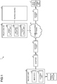
- FIG. 1 is a diagram illustrating an example of an air conditioning system 1 according to an embodiment.
- the air conditioning system 1 illustrated in FIG. 1 includes an indoor unit 2, an adapter 3, a router 4, a server device 5, a relay device 6, a communication terminal 7, and a communication network 8.
- the indoor unit 2 is a part of an air conditioner that is arranged in, for example, a room and that heats or cools the air in the room. Furthermore, a user of the indoor unit 2 can perform a remote operation on the indoor unit 2 operated by a remote controller 9.
- the indoor unit 2 includes a main body 2A and a control unit 2B that controls the main body 2A.
- the main body 2A has an indoor fan and an indoor heat exchanger, and the room air that has been subjected to heat exchange by the indoor heat exchanger is blown out from the main body 2A, whereby air heating, cooling, dehumidification or the like of the room is performed.
- an outdoor unit (not illustrated) has an outdoor fan, a compressor, or the like.
- the communication terminal 7 is a terminal device, such as a smartphone, held by the user.
- the adapter 3 has a communication function for connecting the indoor unit 2 and the router 4 by wireless communication and a control function for performing artificial intelligence (AI) control on the indoor unit 2.
- the adapter 3 is arranged for each of the indoor units 2.
- the router 4 is a device provided at an access point that connects the adapter 3 and the communication network 8 by wireless communication using, for example, a wireless local area network (WLAN) or the like.
- the communication network 8 is a communication network, such as the Internet.
- the server device 5 has a function for generating a learning model of the AI that controls the indoor unit 2 and has a database or the like that stores therein operation history data or the like. Furthermore, the server device 5 is arranged in, for example, a data center.
- the relay device 6 has a function for connecting to the communication network 8 in communication and connecting to the server device 5 in communication.
- the relay device 6 sends operation history data or the like that is used to generate or update the learning model applied to the indoor unit 2 through the communication network 8 from the adapter 3 to the server device 5.
- the relay device 6 sends the learning model generated or updated by the server device 5 to the adapter 3 through the communication network 8.
- the relay device 6 is arranged in, for example, the data center or the like.
- the relay device 6 includes a first relay unit 6A, a second relay unit 6B, and a third relay unit 6C.
- the first relay unit 6A sends various kinds of data related to AI control between the adapter 3 and the server device 5.
- the first relay unit 6A sends, to the server device 5 through the communication network 8, the operation history data or the like that is used to generate or update the learning model received from the adapter 3 and also sends the learning model generated or updated by the server device 5 to the adapter 3 through the communication network 8.
- the second relay unit 6B acquires an operation condition (an operation mode, such as a cooling/heating mode, a set temperature, etc.) of the indoor unit 2 that has been set by using the communication terminal 7 by the user from the outside and sends the acquired operation condition to the indoor unit 2.
- an operation condition an operation mode, such as a cooling/heating mode, a set temperature, etc.
- the third relay unit 6C acquires external data, such as a weather forecast, from, for example, the communication network 8, such as the Internet, and sends the acquired external data to the server device 5. Furthermore, the third relay unit 6C sends the external data to the adapter 3 through the communication network 8.
- external data such as a weather forecast
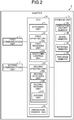
- FIG. 2 is a block diagram illustrating an example of a configuration of the adapter 3.
- the adapter 3 illustrated in FIG. 2 includes a first communication unit 11, a second communication unit 12, a storage unit 13, and a central processing unit (CPU) 14.
- the first communication unit 11 is a communication interface (IF), such as a universal asynchronous receiver transmitter (UART), that performs a communication connection with the control unit 2B included in the indoor unit 2.
- the second communication unit 12 is a communication unit of, for example, communication IF, such as a WLAN, that performs a communication connection with the router 4.
- the storage unit 13 includes, for example, a read only memory (ROM), a random access memory (RAM), or the like and stores various kinds of information, such as data and programs.
- the CPU 14 performs overall control of the adapter 3.
- the storage unit 13 included in the adapter 3 illustrated in FIG. 2 includes an operation history memory 13A that temporarily stores therein the operation history data acquired from the indoor unit 2, a model memory 13B that stores therein a learning model acquired from the server device 5, an external memory 13C that stores therein external data, and a program memory 13D that stores therein an update control purpose program acquired from the server device 5.
- the update control purpose program is a program for updating a control program for the air conditioning system 1 from the server device 5, for example, a program for updating firmware or the like of the control unit 2B that controls the indoor unit 2.
- the model memory 13B includes a plurality of storage areas 130, such as a first area 130A, a second area 130B, and a third area 130C.
- Examples of the status of each of the storage areas 130 include a state in which a written learning model can be read out (hereinafter, simply referred to as during readout), a state in which a new learning model is in the course of writing (hereinafter, simply referred to as during write), and a state in which a learning model is in a state other than during the readout operation and has already been written.
- the CPU 14 includes an acquiring unit 21, a first updating unit 22, a second updating unit 23, and a prediction control unit 24.
- the acquiring unit 21 acquires the operation history data from the indoor unit 2 at an acquiring timing of, for example, every 5 minutes in a predetermined period.
- the acquiring unit 21 stores the operation history data acquired in a period of 5 minutes in the operation history memory 13A.
- the acquiring unit 21 sends the operation history data that is being stored in the operation history memory 13A to the server device 5 through the communication network 8.
- the first updating unit 22 receives the learning model from the server device 5 through the communication network 8 and stores the received learning model in the model memory 13B by using a first update method.
- the first updating unit 22 includes a first receiving unit 22A and a switching control unit 22B.
- the first receiving unit 22A receives a new learning model from the server device 5 through the communication network 8 and stores the received new learning model in the model memory 13B.
- the switching control unit 22B writes the new learning model to the storage area 130 and switches the status of the storage area 130 that is in the state of during write the new learning model to the status of during readout.
- the first update method is a method for overwriting and storing the new learning model received by the first receiving unit 22A in the written storage area 130.
- FIG. 3 is a diagram illustrating an example of writing and reading out each of the storage areas 130 in the model memory 13B. Furthermore, for convenience of description, it is assumed that, in a state of a situation A1, for example, a learning model (current model) that is in the state of during readout is stored in the first area 130A, a written learning model (last model) is stored in the third area 130C, and a new learning model (latest model) is written to the second area 130B, and it is assumed that, in the situation A2, the above described writing operation has already been completed. In the state of the situation A2, the latest learning model is stored in the second area 130B.
- a learning model current model
- last model is stored in the third area 130C
- latest model new learning model
- control of the air conditioning system 1 based on the learning model is performed by the latest learning model (current model) stored in the second area 130B (the second area 130B enters the state of during readout).
- the learning model stored in the first area 130A is changed to the learning model of the last time (last model).
- the learning model stored in the third area 130C is changed to the learning model before last (model before last).
- the first receiving unit 22A receives a new learning model from the server device 5 in the state of the situation A2
- the first receiving unit 22A writes, in an overwriting manner, the new learning model (latest model) and the receipt time into the already written third area 130C in which a learning model having the oldest receipt time (model before last) is written, except for the second area 130B in which the learning model (current model) is being read out. Consequently, the switching control unit 22B sets the state of the third area 130C to be in the state of during write (the situation B1). When the writing has been completed, the state enters the situation B2.
- control of the air conditioning system 1 based on the learning model is performed by the latest learning model (current model) stored in the third area 130C (the third area 130C enters the state of during readout).
- the learning model stored in the second area 130B is changed to the learning model last time (last model).
- the learning model stored in the first area 130A is changed to the learning model before last (model before last).
- the first receiving unit 22A when the first receiving unit 22A receives a new learning model from the server device 5 in the state of the situation B2, the first receiving unit 22A writes, in an overwriting manner, a new learning model (latest model) and the receipt time into the already written first area 130A in which a learning model having the oldest receipt time (model before last) is written, except for the third area 130C in which the learning model (current model) is being read out. Consequently, the switching control unit 22B sets the state of the first area 130A to be in the state of during write (a situation C1). When the writing has been completed, the state enters the situation C2.
- control of the air conditioning system 1 based on the learning model is performed by the latest learning model (current model) stored in the first area 130A (the first area 130A enters the state of during readout).
- the learning model stored in the third area 130C is changed to the learning model last time (last model).
- the learning model stored in the second area 130B is changed to the learning model before last (model before last). Then, the situation is sequentially switched by the switching control unit 22B every time a new learning model is received.
- the second updating unit 23 receives an update control purpose program for the control unit 2B included in the indoor unit 2 from the server device 5, the second updating unit 23 rewrites, regarding the update control purpose program, the control purpose program for the control unit 2B by using the second update method that is different from the first update method.
- the second updating unit 23 includes a second receiving unit 23A and a second sending unit 23B.
- the second receiving unit 23A stores the update control purpose program received from the server device 5 into the program memory 13D.
- the second sending unit 23B sends the update control purpose program stored in the program memory 13D to the control unit 2B included in the indoor unit 2.
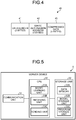
- FIG. 4 is a diagram illustrating an example of a data structure of a split data 40 included in the update control purpose program.
- the update control purpose program is constituted by a plurality of pieces of the split data 40 having a predetermined split data length.
- the split data 40 includes a data length 41, a write destination address 42, and a compressed data 43.
- the data length 41 is information (2 bytes) on the data length from the write destination address 42 to the compressed data 43.
- the write destination address 42 is address information (3 bytes) at the time of writing data to a block 52A included in a ROM 52 in the control unit 2B in the indoor unit 2 that is, for example, a target apparatus.
- the compressed data 43 is data with n bytes compressed by using a predetermined method.
- the capacity of the decompressed data of the compressed data 43 corresponds to, for example, the storage capacity of 1K byte (1024 bytes) of a single block in the ROM 52.
- the data length 41 and the write destination address 42 are not compressed
- the second receiving unit 23A receives the split data 40 included in the update control purpose program from the server device 5 in units of split data. After having received the entire update control purpose program, the second receiving unit 23A sequentially stores the received split data 40 in the program memory 13D. Regarding the split data 40 stored in the program memory 13B, the second sending unit 23B refers to the data length 41 included in the split data 40, extracts data having the data length from the update control purpose program, and sequentially sends the split data 40 to the control unit 2B included in the indoor unit 2. After the indoor unit 2 receives the split data 40, the indoor unit 2 decompresses the split data 40 and writes the decompressed split data 40 to the block 52A.
- the second sending unit 23B included in the adapter 3 includes a judging unit 23C that judges whether, when it is detected that the completion of writing of the split data 40 that has been sent from the indoor unit 2 onto the block 52A, the split data 40 that has not been sent to the indoor unit 2 is present in the program memory 13D.
- the second sending unit 23B sends the unsent split data 40 to the control unit 2B included in the indoor unit 2.
- the prediction control unit 24 controls the control unit 2B included in the indoor unit 2 based on the learning model. Furthermore, for convenience of description, a case in which the prediction control unit 24 controls the control unit 2B included in the indoor unit 2 based on the learning model has been exemplified; however, the prediction control unit 24 may also directly control the main body 2A included in the indoor unit 2 based on the learning model. Furthermore, the prediction control unit 24 transits a control mode based on the learning model to the control unit 2B. Namely, the prediction control unit 24 may also indirectly control the main body 2A via the control unit 2B, and modifications are possible as needed.
- the CPU 14 included in the adapter 3 detects a download request for the learning model, the CPU 14 executes a first updating process and, when the CPU 14 detects a download request for the update control program, the CPU 14 executes an update switching process that performs a second updating process.
- FIG. 5 is a block diagram illustrating an example of a configuration of the server device 5.
- the server device 5 illustrated in FIG. 5 includes a communication unit 31, a storage unit 32, and a CPU 33.
- the communication unit 31 is a communication IF that performs a communication connection to the relay device 6.
- the storage unit 32 includes, for example, a hard disk drive (HDD), a ROM, a RAM, and the like and stores various kinds of information, such as data and programs.
- the CPU 33 performs overall control of the server device 5.
- the storage unit 32 included in the server device 5 illustrated in FIG. 5 includes a data memory 32A, a model storage unit 32B, and a program storage unit 32C.
- the data memory 32A stores therein operation history data or the like received from each of the adapters 3.
- the model storage unit 32B stores therein the learning model that is generated or updated by the server device 5.
- the program storage unit 32C stores therein the plurality of pieces of the split data 40 included in the update control purpose program that is generated or updated by the server device 5 in units of the split data 40.
- the CPU 33 included in the server device 5 includes a model learning unit 33A, a receiving unit 33B, and a sending unit 33C.
- the model learning unit 33A connects each of the adapters 3 included in the plurality of the indoor units 2 and receives operation history data by an amount corresponding to 48 hours from each of the adapters 3 through the router 4, the communication network 8, and the relay device 6. Then, the model learning unit 33A performs learning by using the operation history data by an amount corresponding to 48 hours that is being stored in the data memory 32A received from each of the adapters 3, and then, generates or updates the learning model of each of the indoor units 2.
- the learning model includes, for example, a sensible temperature set prediction model that predicts a sensible temperature of a user in a room five minutes later in accordance with an operation situation of the air conditioner in individual home and that controls an air conditioner in accordance with the sensible temperature to be predicted.
- the model learning unit 33A generates or updates the learning models associated with the respective adapters 3 based on the operation history data, by an amount corresponding to 48 hours for each of the adapters 3, that is being stored in the data memory 32A and stores the generated or the updated learning model in the model storage unit 32B.
- the sending unit 33C sends the learning model that has been generated or updated in the model learning unit 33A to the adapter 3 through the relay device 6, the communication network 8, and the router 4. Furthermore, the sending unit 33C sends the split data 40 included in the update control purpose program stored in the program storage unit 32C to the adapter 3 through the relay device 6, the communication network 8, and the router 4.
- FIG. 6 is a block diagram illustrating an example of a configuration of the control unit 2B in the indoor unit 2.
- the control unit 2B illustrated in FIG. 6 includes an indoor unit microcomputer 51 and a read only memory (ROM) 52.
- the ROM 52 includes a plurality of the blocks 52A and the storage capacity of each of the blocks 52A is assumed to be 1024 bytes.
- the write destination address 42 of the split data 40 that is an address for identifying each of the blocks 52A included in the ROM 52.
- the indoor unit microcomputer 51 is a receiving unit 51A, a decompressing unit 51B, an updating unit 51C, and an executing unit 51D.
- the receiving unit 51A receives the split data 40 included in the update control purpose program sent from the adapter 3.
- the decompressing unit 51B refers to the write destination address 42 included in the split data 40 and decompresses the compressed data 43 included in the split data 40.
- the updating unit 51C refers to the write destination address 42 included in the split data 40 and overwrites the decompressed data to the block 52A that is included in the ROM 52 and that is associated with the write destination address 42.
- the executing unit 51D reboots the indoor unit microcomputer 51. Whether or not the data is normal is determined whether, for example, a checksum value of the entire of the overwritten update control purpose program matches the value that is added to the update control purpose program as data. Furthermore, when the indoor unit microcomputer 51 performs a reboot, the indoor unit microcomputer 51 temporarily stops the indoor unit 2.
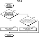
- FIG. 7 is a flowchart illustrating an example of a processing operation performed by the CPU 14 included in the adapter 3 according to the update switching process.
- the first updating unit 22 included in the CPU 14 in the adapter 3 judges whether the download request for the learning model from the server device 5 has been detected (Step S11).
- the first updating unit 22 performs the first updating process illustrated in FIG. 8 (Step S12), and ends the processing operation illustrated in FIG. 7 .
- the first updating process is a process of updating the learning model performed by using the first update method.
- the second updating unit 23 included in the CPU 14 judges whether the download request for the update control purpose program from the server device 5 has been detected (Step S13). If the second updating unit 23 has detected the download request for the update control purpose program (Yes at Step S13), the second updating unit 23 performs the second updating process illustrated in FIG. 9 (Step S14), and ends the processing operation illustrated in FIG. 7 . Furthermore, the second updating process is a process of updating the control purpose program for the control unit 2B in the indoor unit 2 performed by using the second update method. Furthermore, if the download request for the update control purpose program is not detected (No at Step S13), the CPU 14 ends the processing operation illustrated in FIG. 7 .
- the adapter 3 updates the learning model by using the first update method and, if the adapter 3 has detected a download request for the update control purpose program from the server device 5, the adapter 3 updates the control purpose program included in the control unit 2B in the indoor unit 2 by using the second update method.
- the adapter 3 allows the control unit 2B included in the indoor unit 2 to overwrite the split data 40 by sequentially sending the split data 40 to the indoor unit 2 without performing a process (in other words, a "useless process") other than the process that is originally needed to the adapter (for example, transmission and reception of data and storing the learning model), whereby it is possible to reduce a load applied to the adapter 3.
- a process in other words, a "useless process”
- FIG. 8 is a flowchart illustrating an example of the processing operation performed by the CPU 14 included in the adapter 3 according to the first updating process.
- the first updating unit 22 included in the CPU 14 judges whether the latest learning model in the storage area 130 is being read out (Step S21). If the learning model in the storage area 130 is being read out (Yes at Step S21), the first receiving unit 22A included in the first updating unit 22 starts to download a new learning model from the server device 5 (Step S22).
- the switching control unit 22B included in the first updating unit 22 writes the new learning model downloaded by the first receiving unit 22A to the storage area 130 that is in the state of during write (Step S23), and judges whether control performed based on the latest learning model (current model) in the storage area 130 that is in the state of during readout has been completed (Step S24). Furthermore, the control performed based on the latest learning model (current model) in the storage area 130 that is in the state of during readout mentioned here is control for providing a recommended operation to the control unit 2B included in the indoor unit 2 based on the learning model (current model) in the storage area 130.
- the switching control unit 22B switches the status of the storage area 130 in which the new learning model has been written to the "storage area 130 in which the latest learning model has been stored", switches the status of the storage area 130 in which the learning model was reading out to the "storage area 130 in which the last time learning model is stored”, switches the status of the already written storage area 130 to the "storage area 130 in which the before last learning model has been stored” (Step S25), and ends the processing operation illustrated in FIG. 8 .
- the first receiving unit 22A starts to download a new learning model from the server device 5 (Step S26).
- the switching control unit 22B writes the new learning model downloaded by the first receiving unit 22A to the storage area 130 (Step S27), and moves to the process at Step S25 in order to switch the status of the storage area 130 in which the new learning model has been written.
- the first updating unit 22 If the first updating unit 22 does not complete the control based on the latest learning model (current model) in the storage area 130 that is in the state of during readout (No at Step S24), the first updating unit 22 returns to the process at Step S24 in order to judge whether the control has been completed.
- the adapter 3 writes the new learning model and the receipt time to the written storage area 130 having the oldest receipt time from among the plurality of the storage areas 130 except for the storage area 130 that is in the state of during readout.
- the adapter 3 can overwrite the new learning model in the model memory 13B while using the learning model that is in the state of during readout. Accordingly, it is possible to avoid a situation of a stop of the indoor unit 2 even when the learning model is updated.
- FIG. 9 is a flowchart illustrating an example of the processing operation performed by the CPU 14 included in the adapter 3 according to the second updating process.
- the second receiving unit 23A included in the second updating unit 23 in the CPU 14 starts to download the plurality of pieces of the split data 40 included in the update control purpose program from the server device 5 (Step S31), and stores the split data 40 in the program memory 13D (Step S32).
- the second updating unit 23 judges whether the program update timing has been detected (Step S33).
- the program update timing is, for example, whether an update of the update control purpose program is possible on the control unit 2B side included in the indoor unit 2, for example, whether it is update time (absence time of a user) of the update control purpose program designated by the user of the indoor unit 2.
- the second sending unit 23B included in the second updating unit 23 detects the program update timing (Yes at Step S33)
- the second sending unit 23B reads out, from the program memory 13D, the unsent split data 40 (Step S34), refers to the data length 41 of the read out split data 40, extracts the data by an amount corresponding to the data length from the update control purpose program, and sends the extracted split data 40 to the control unit 2B in the indoor unit 2 (Step S35).
- the adapter 3 can sequentially send the pieces of the split data 40 to the indoor unit 2 without performing the process (in other words, a "useless process") other than the process that is originally needed for the adapter (for example, transmission and reception of data and storing the learning model), it is possible to reduce a processing load applied to the adapter.
- the second sending unit 23B judges whether a notification of completion of overwriting of the split data 40 sent from the control unit 2B has been detected (Step S36). If the notification of completion of overwriting of the sent split data 40 sent from the control unit 2B has been detected (Yes at Step S36), the judging unit 23C judges whether the unsent split data 40 is present in the program memory 13D (Step S37). If the unsent split data 40 is present in the program memory 13D (No at Step S37), the second updating unit 23 determines that transmission of all of the pieces of the split data 40 included in the update control purpose program with respect to the control unit 2B has been completed, and ends the processing operation illustrated in FIG. 9 .
- the second updating unit 23 If the second updating unit 23 does not detect the program update timing (No at Step S33), the second updating unit 23 returns to the process at Step S33 in order to determine whether the program update timing has been detected. If the second updating unit 23 does not detect the notification of overwriting of the split data 40 sent from the control unit 2B (No at Step S36), the second updating unit 23 returns to the process at Step S36 in order to determine whether the notification of completion of overwriting of the split data 40 sent from the control unit 2B has been detected.
- the second sending unit 23B returns to the process at Step S34 in order to read out the unsent split data 40 from the program memory 13D.
- the adapter 3 sequentially receives each of the plurality of pieces of the split data 40 included in the update control purpose program from the server device 5 and stores the received split data 40 in the program memory 13D.
- the adapter 3 sequentially sends the unsent split data 40 included in the update control purpose program stored in the program memory 13D to the control unit 2B included in the indoor unit 2.
- the adapter 3 can sequentially send large volumes of the split data 40 included in the update control purpose program to the control unit 2B without performing the useless process, it is possible to reduce the processing load applied to the adapter.
- FIG. 10 is a flowchart illustrating an example of the processing operation of the indoor unit microcomputer 51 included in the control unit 2B related to the updating process performed on the microcomputer side.
- the receiving unit 51A included in the indoor unit microcomputer 51 judges whether the plurality of pieces of the split data 40 has been received from the adapter 3 (Step S41).
- the decompressing unit 51B included in the indoor unit microcomputer 51 receives the plurality of pieces of the split data 40 from the adapter 3 (Yes at Step S41)
- the decompressing unit 51B refers to the write destination address 42 in the received split data 40 and decompresses only the compressed data 43 in the received split data 40 (Step S42).
- the updating unit 51C included in the indoor unit microcomputer 51 starts an operation of writing the decompressed data to the block 52A that is included in the ROM 52 and that is associated with the write destination address 42 (Step S43), and judges whether writing of the data to the subject block 52A has been completed (Step S44). Furthermore, in the indoor unit microcomputer 51, it is possible to write the decompressed data to the block 52A by referring to the write destination address 42 in the split data 40. As a result, it is possible to improve a decrease in time needed to the writing operation and improve suppression of degradation of the ROM 52 due to useless writing.
- Step S44 When the updating unit 51C has completed writing of the data to the subject block 52A (Yes at Step S44), the updating unit 51C notifies the adapter 3 of the completion of writing of the split data 40 (Step S45).
- the updating unit 51C judges whether all of the pieces of the split data 40 included in the update control purpose program have been received (Step S46). If the updating unit 51C has received all of the pieces of the split data 40 included in the update control purpose program (Yes at Step S46), the updating unit 51C judges, based on the checksum value, whether all of the pieces of data in which writing has been completed are normal (Step S47).
- Step S47 If all of the pieces of data in which writing has been completed are normal (Yes at Step S47), the executing unit 51D included in the indoor unit microcomputer 51 executes a reboot of the indoor unit microcomputer 51 (Step S48), and ends the processing operation illustrated in FIG. 10 .
- the receiving unit 51A does not receive the split data 40 from the adapter 3 (No at Step S41), the receiving unit 51A returns to the process at Step S41 in order to judge whether the split data 40 has been received. If the writing of the data has not been completed (No at Step S44), the updating unit 51C returns to the process at Step S44 in order to continue monitoring whether writing of data started at Step S43 has been completed.
- the updating unit 51C If the updating unit 51C does not receive all of the pieces of the split data 40 (No at Step S46), the updating unit 51C returns to the process at Step S41 in order to judge whether the split data 40 has been received from the adapter 3. If not all of the pieces of the data in which writing has been completed are normal (No at Step S47), the updating unit 51C reports a user of, for example, an unwritable state, and ends the processing operation illustrated in FIG. 10 .
- the control unit 2B included in the indoor unit 2 receives the split data 40 from the adapter 3, decompresses the compressed data 43 included in the received split data 40, and writs the decompressed data to the block 52A associated with the write destination address 42 in the split data 40. Then, after the control unit 2B writes all of the pieces of decompressed data in the split data 40 included in the update control purpose program to all of the blocks 52A, the control unit 2B reboots the indoor unit 2 if all of the pieces data in which writing has been completed are normal. As a result, the control unit 2B included in the indoor unit 2 can update the update control purpose program while improving a decrease in time needed to the writing operation and suppression of degradation of the ROM 52 due to useless writing.
- the adapter 3 updates the learning model by using the first update method and updates the program for the control unit 2B by using the second update method.
- the update methods are different between the update of the learning model and the update of the program, it is possible to reduce the load applied to the adapter 3.
- the update control purpose program of the air conditioning system 1 for example, the update control purpose program for updating the firmware of the indoor unit 2 has been exemplified; however, it may also be able to use an update control purpose program for updating the firmware of the adapter 3, an update control purpose program for updating the firmware of the control unit 2B that controls the indoor unit 2, or the like, and modifications are possible as needed.
- the storage area 130 included in the model memory 13B in the adapter 3 is constituted by the first area 130A, the second area 130B, and the third area 130C.
- the configuration is not limited to these three storage areas 130 as long as, for example, at least two or more of the storage areas 130 are used, and modifications are possible as needed.
- the indoor unit microcomputer 51 may also decompress the split data and compare the decompressed data with the data stored in the block 52A targeted for the write operation. If the pieces of compared data are the same, the indoor unit microcomputer 51 may also compare, without writing the data to the subject block 52A, the subsequent decompressed data with the data stored in the block 52A targeted for the write operation. As a result, by reducing the number of times of useless writing operations, it is possible to extend the life of the indoor unit microcomputer 51.
- the adapter 3 does not need to check whether there is a need to perform a write operation in the subject block 52A for each of the pieces of the split data 40.
- each unit illustrated in the drawings is not always physically configured as illustrated in the drawings.
- the specific shape of a separate or integrated device is not limited to the drawings.
- all or part of the device can be configured by functionally or physically separating or integrating any of the units depending on various loads or use conditions.
- each unit may also be executed by a central processing unit (CP) (or a microcomputer, such as a micro processing unit (MPU), a micro controller unit (MCU), or the like).
- CP central processing unit
- MPU micro processing unit
- MCU micro controller unit
- all or any part of various processing functions may also be, of course, executed by programs analyzed and executed by the CPU (or the microcomputer, such as the MPU or the MCU), or executed by hardware by wired logic.
Landscapes
- Engineering & Computer Science (AREA)
- Signal Processing (AREA)
- Chemical & Material Sciences (AREA)
- Combustion & Propulsion (AREA)
- Mechanical Engineering (AREA)
- General Engineering & Computer Science (AREA)
- Physics & Mathematics (AREA)
- Fuzzy Systems (AREA)
- Mathematical Physics (AREA)
- Human Computer Interaction (AREA)
- Stored Programmes (AREA)
- Air Conditioning Control Device (AREA)
Abstract
Description
- The present invention relates to an air conditioning system.
- An air conditioning system having a learning function can reflect, if a storage unit has the learning function, a suitable temperature environment in time series obtained based on the preferences, action patterns, or the like of residents or the like in control performed based on the standard specification setting (for example, Patent Literature 1).
- Furthermore, there is a known system for receiving an update purpose control program from a server device and automatically performing an update, when, for example, an air conditioning system receives a notification of updating a control program stored in the air conditioning system from a server device (for example , Patent Literature 2).
-
- Patent Literature 1:
Japanese Laid-open Patent Publication No. 2015-117933 - Patent Literature 2:
Japanese Laid-open Patent Publication No. 2008-190853 - If an adapter that relays communication between the server device and an indoor unit is used, it is conceivable to allow the adapter to have a function for receiving the update purpose control program for the indoor unit from the server device, temporarily storing the received update purpose control program in the adapter, and sending the temporarily stored update purpose control program to the indoor unit. In contrast, it is conceivable to allow the server device to perform machine learning and generate a trained model based on the collected data by allowing the adapter to periodically collect operation data, such as a preferred temperature and an air flow, of the residents or the like from the indoor unit and send the collected data to the server device. In this case, by allowing the trained model to be stored in the adapter, the adapter can provide a recommended operation to a control unit included in the indoor unit by using the storing learning model. Furthermore, it is conceivable to allow the adapter to have a function for receiving a new learning model from the server device and updating the storing learning model to the received new learning model.
- The inventors of the present application found a problem in that, if the adapter is allowed to have the above described function, a processing load of the adapter is increased due to an update of the learning model and the control program.
- Accordingly, the present invention has been conceived in light of the circumstances described above and an object thereof is to provide an air conditioning system that can reduce an adapter load by updating the learning model and the control program by using different methods.
- According to an aspect, an air conditioning system includes an air conditioner and an adapter that connects the air conditioner and an external server device. The adapter includes a first updating unit and a second updating unit. The first updating unit updates, when a new learning model that provides a recommended operation to a control unit included in the air conditioner is received from the external server device, the learning model by using a first update method. The second updating unit updates, when an update purpose control program that updates a control program for the air conditioner is received from the external server device, the update purpose control program by using a second update method that is different from the first update method.
- As an aspect of an embodiment, it is possible to reduce an adapter load by updating the learning model and the control program by using different methods.
-
-
FIG. 1 is a diagram illustrating an example of an air conditioning system according to an embodiment. -
FIG. 2 is a block diagram illustrating an example of a configuration of an adapter. -
FIG. 3 is a diagram illustrating an example of writing and reading out each storage area in a model memory. -
FIG. 4 is a diagram illustrating an example of a data structure of split data included in an update control purpose program. -
FIG. 5 is a block diagram illustrating an example of a configuration of a server device. -
FIG. 6 is a block diagram illustrating an example of a configuration of a control unit included in an indoor unit. -
FIG. 7 is a flowchart illustrating an example of a processing operation of a CPU included in the adapter related to an update switching process. -
FIG. 8 is a flowchart illustrating an example of a processing operation of the CPU included in the adapter related to a first updating process. -
FIG. 9 is a flowchart illustrating an example of a processing operation of the CPU included in the adapter related to a second updating process. -
FIG. 10 is a flowchart illustrating an example of a processing operation of an indoor unit microcomputer included in the control unit related to an updating process performed on the microcomputer side. - Preferred embodiments of an air conditioning system disclosed in the present invention will be explained with reference to accompanying drawings. Furthermore, the disclosed technology is not limited to each of the embodiments. Furthermore, the embodiments described below may also be modified as long as the embodiments do not conflict with each other.
-
FIG. 1 is a diagram illustrating an example of an air conditioning system 1 according to an embodiment. The air conditioning system 1 illustrated inFIG. 1 includes anindoor unit 2, anadapter 3, a router 4, aserver device 5, a relay device 6, a communication terminal 7, and acommunication network 8. - The
indoor unit 2 is a part of an air conditioner that is arranged in, for example, a room and that heats or cools the air in the room. Furthermore, a user of theindoor unit 2 can perform a remote operation on theindoor unit 2 operated by a remote controller 9. Theindoor unit 2 includes a main body 2A and acontrol unit 2B that controls the main body 2A. The main body 2A has an indoor fan and an indoor heat exchanger, and the room air that has been subjected to heat exchange by the indoor heat exchanger is blown out from the main body 2A, whereby air heating, cooling, dehumidification or the like of the room is performed. Furthermore, an outdoor unit (not illustrated) has an outdoor fan, a compressor, or the like. The communication terminal 7 is a terminal device, such as a smartphone, held by the user. - The
adapter 3 has a communication function for connecting theindoor unit 2 and the router 4 by wireless communication and a control function for performing artificial intelligence (AI) control on theindoor unit 2. Theadapter 3 is arranged for each of theindoor units 2. The router 4 is a device provided at an access point that connects theadapter 3 and thecommunication network 8 by wireless communication using, for example, a wireless local area network (WLAN) or the like. Thecommunication network 8 is a communication network, such as the Internet. Theserver device 5 has a function for generating a learning model of the AI that controls theindoor unit 2 and has a database or the like that stores therein operation history data or the like. Furthermore, theserver device 5 is arranged in, for example, a data center. The relay device 6 has a function for connecting to thecommunication network 8 in communication and connecting to theserver device 5 in communication. The relay device 6 sends operation history data or the like that is used to generate or update the learning model applied to theindoor unit 2 through thecommunication network 8 from theadapter 3 to theserver device 5. Furthermore, the relay device 6 sends the learning model generated or updated by theserver device 5 to theadapter 3 through thecommunication network 8. Furthermore, the relay device 6 is arranged in, for example, the data center or the like. - The relay device 6 includes a first relay unit 6A, a second relay unit 6B, and a third relay unit 6C. The first relay unit 6A sends various kinds of data related to AI control between the
adapter 3 and theserver device 5. The first relay unit 6A sends, to theserver device 5 through thecommunication network 8, the operation history data or the like that is used to generate or update the learning model received from theadapter 3 and also sends the learning model generated or updated by theserver device 5 to theadapter 3 through thecommunication network 8. The second relay unit 6B acquires an operation condition (an operation mode, such as a cooling/heating mode, a set temperature, etc.) of theindoor unit 2 that has been set by using the communication terminal 7 by the user from the outside and sends the acquired operation condition to theindoor unit 2. The third relay unit 6C acquires external data, such as a weather forecast, from, for example, thecommunication network 8, such as the Internet, and sends the acquired external data to theserver device 5. Furthermore, the third relay unit 6C sends the external data to theadapter 3 through thecommunication network 8. -
FIG. 2 is a block diagram illustrating an example of a configuration of theadapter 3. Theadapter 3 illustrated inFIG. 2 includes afirst communication unit 11, asecond communication unit 12, astorage unit 13, and a central processing unit (CPU) 14. Thefirst communication unit 11 is a communication interface (IF), such as a universal asynchronous receiver transmitter (UART), that performs a communication connection with thecontrol unit 2B included in theindoor unit 2. Thesecond communication unit 12 is a communication unit of, for example, communication IF, such as a WLAN, that performs a communication connection with the router 4. Thestorage unit 13 includes, for example, a read only memory (ROM), a random access memory (RAM), or the like and stores various kinds of information, such as data and programs. TheCPU 14 performs overall control of theadapter 3. - The
storage unit 13 included in theadapter 3 illustrated inFIG. 2 includes anoperation history memory 13A that temporarily stores therein the operation history data acquired from theindoor unit 2, amodel memory 13B that stores therein a learning model acquired from theserver device 5, anexternal memory 13C that stores therein external data, and aprogram memory 13D that stores therein an update control purpose program acquired from theserver device 5. Furthermore, the update control purpose program is a program for updating a control program for the air conditioning system 1 from theserver device 5, for example, a program for updating firmware or the like of thecontrol unit 2B that controls theindoor unit 2. - The
model memory 13B includes a plurality ofstorage areas 130, such as afirst area 130A, asecond area 130B, and athird area 130C. Examples of the status of each of thestorage areas 130 include a state in which a written learning model can be read out (hereinafter, simply referred to as during readout), a state in which a new learning model is in the course of writing (hereinafter, simply referred to as during write), and a state in which a learning model is in a state other than during the readout operation and has already been written. - The
CPU 14 includes an acquiring unit 21, a first updating unit 22, asecond updating unit 23, and a prediction control unit 24. - The acquiring unit 21 acquires the operation history data from the
indoor unit 2 at an acquiring timing of, for example, every 5 minutes in a predetermined period. The acquiring unit 21 stores the operation history data acquired in a period of 5 minutes in theoperation history memory 13A. The acquiring unit 21 sends the operation history data that is being stored in theoperation history memory 13A to theserver device 5 through thecommunication network 8. - The first updating unit 22 receives the learning model from the
server device 5 through thecommunication network 8 and stores the received learning model in themodel memory 13B by using a first update method. The first updating unit 22 includes afirst receiving unit 22A and aswitching control unit 22B. Thefirst receiving unit 22A receives a new learning model from theserver device 5 through thecommunication network 8 and stores the received new learning model in themodel memory 13B. When the new learning model is received from theserver device 5, the switchingcontrol unit 22B writes the new learning model to thestorage area 130 and switches the status of thestorage area 130 that is in the state of during write the new learning model to the status of during readout. Furthermore, the first update method is a method for overwriting and storing the new learning model received by thefirst receiving unit 22A in the writtenstorage area 130. -
FIG. 3 is a diagram illustrating an example of writing and reading out each of thestorage areas 130 in themodel memory 13B. Furthermore, for convenience of description, it is assumed that, in a state of a situation A1, for example, a learning model (current model) that is in the state of during readout is stored in thefirst area 130A, a written learning model (last model) is stored in thethird area 130C, and a new learning model (latest model) is written to thesecond area 130B, and it is assumed that, in the situation A2, the above described writing operation has already been completed. In the state of the situation A2, the latest learning model is stored in thesecond area 130B. Accordingly, control of the air conditioning system 1 based on the learning model is performed by the latest learning model (current model) stored in thesecond area 130B (thesecond area 130B enters the state of during readout). In this case, the learning model stored in thefirst area 130A is changed to the learning model of the last time (last model). Furthermore, the learning model stored in thethird area 130C is changed to the learning model before last (model before last). - If the
first receiving unit 22A receives a new learning model from theserver device 5 in the state of the situation A2, thefirst receiving unit 22A writes, in an overwriting manner, the new learning model (latest model) and the receipt time into the already writtenthird area 130C in which a learning model having the oldest receipt time (model before last) is written, except for thesecond area 130B in which the learning model (current model) is being read out. Consequently, the switchingcontrol unit 22B sets the state of thethird area 130C to be in the state of during write (the situation B1). When the writing has been completed, the state enters the situation B2. Namely, control of the air conditioning system 1 based on the learning model is performed by the latest learning model (current model) stored in thethird area 130C (thethird area 130C enters the state of during readout). In this case, the learning model stored in thesecond area 130B is changed to the learning model last time (last model). Furthermore, the learning model stored in thefirst area 130A is changed to the learning model before last (model before last). - Similarly, when the
first receiving unit 22A receives a new learning model from theserver device 5 in the state of the situation B2, thefirst receiving unit 22A writes, in an overwriting manner, a new learning model (latest model) and the receipt time into the already writtenfirst area 130A in which a learning model having the oldest receipt time (model before last) is written, except for thethird area 130C in which the learning model (current model) is being read out. Consequently, the switchingcontrol unit 22B sets the state of thefirst area 130A to be in the state of during write (a situation C1). When the writing has been completed, the state enters the situation C2. Namely, control of the air conditioning system 1 based on the learning model is performed by the latest learning model (current model) stored in thefirst area 130A (thefirst area 130A enters the state of during readout). In this case, the learning model stored in thethird area 130C is changed to the learning model last time (last model). Furthermore, the learning model stored in thesecond area 130B is changed to the learning model before last (model before last). Then, the situation is sequentially switched by the switchingcontrol unit 22B every time a new learning model is received. - In the following, a second update method will be described. When the
second updating unit 23 receives an update control purpose program for thecontrol unit 2B included in theindoor unit 2 from theserver device 5, thesecond updating unit 23 rewrites, regarding the update control purpose program, the control purpose program for thecontrol unit 2B by using the second update method that is different from the first update method. Thesecond updating unit 23 includes asecond receiving unit 23A and asecond sending unit 23B. Thesecond receiving unit 23A stores the update control purpose program received from theserver device 5 into theprogram memory 13D. Thesecond sending unit 23B sends the update control purpose program stored in theprogram memory 13D to thecontrol unit 2B included in theindoor unit 2. -
FIG. 4 is a diagram illustrating an example of a data structure of asplit data 40 included in the update control purpose program. The update control purpose program is constituted by a plurality of pieces of thesplit data 40 having a predetermined split data length. Thesplit data 40 includes adata length 41, awrite destination address 42, and acompressed data 43. Thedata length 41 is information (2 bytes) on the data length from thewrite destination address 42 to the compresseddata 43. Thewrite destination address 42 is address information (3 bytes) at the time of writing data to ablock 52A included in aROM 52 in thecontrol unit 2B in theindoor unit 2 that is, for example, a target apparatus. Thecompressed data 43 is data with n bytes compressed by using a predetermined method. The capacity of the decompressed data of the compresseddata 43 corresponds to, for example, the storage capacity of 1K byte (1024 bytes) of a single block in theROM 52. For example, thedata length 41 and thewrite destination address 42 are not compressed. - The
second receiving unit 23A receives thesplit data 40 included in the update control purpose program from theserver device 5 in units of split data. After having received the entire update control purpose program, thesecond receiving unit 23A sequentially stores the received splitdata 40 in theprogram memory 13D. Regarding thesplit data 40 stored in theprogram memory 13B, thesecond sending unit 23B refers to thedata length 41 included in thesplit data 40, extracts data having the data length from the update control purpose program, and sequentially sends thesplit data 40 to thecontrol unit 2B included in theindoor unit 2. After theindoor unit 2 receives thesplit data 40, theindoor unit 2 decompresses thesplit data 40 and writes the decompressedsplit data 40 to theblock 52A. Furthermore, after theindoor unit 2 has written the split data to theblock 52A, theindoor unit 2 notifies theadapter 3 of the completion of writing of thesplit data 40. Thesecond sending unit 23B included in theadapter 3 includes a judgingunit 23C that judges whether, when it is detected that the completion of writing of thesplit data 40 that has been sent from theindoor unit 2 onto theblock 52A, thesplit data 40 that has not been sent to theindoor unit 2 is present in theprogram memory 13D. When thesplit data 40 that has not been sent is present in theprogram memory 13D, thesecond sending unit 23B sends theunsent split data 40 to thecontrol unit 2B included in theindoor unit 2. - The prediction control unit 24 controls the
control unit 2B included in theindoor unit 2 based on the learning model. Furthermore, for convenience of description, a case in which the prediction control unit 24 controls thecontrol unit 2B included in theindoor unit 2 based on the learning model has been exemplified; however, the prediction control unit 24 may also directly control the main body 2A included in theindoor unit 2 based on the learning model. Furthermore, the prediction control unit 24 transits a control mode based on the learning model to thecontrol unit 2B. Namely, the prediction control unit 24 may also indirectly control the main body 2A via thecontrol unit 2B, and modifications are possible as needed. When theCPU 14 included in theadapter 3 detects a download request for the learning model, theCPU 14 executes a first updating process and, when theCPU 14 detects a download request for the update control program, theCPU 14 executes an update switching process that performs a second updating process. -
FIG. 5 is a block diagram illustrating an example of a configuration of theserver device 5. Theserver device 5 illustrated inFIG. 5 includes acommunication unit 31, astorage unit 32, and aCPU 33. Thecommunication unit 31 is a communication IF that performs a communication connection to the relay device 6. Thestorage unit 32 includes, for example, a hard disk drive (HDD), a ROM, a RAM, and the like and stores various kinds of information, such as data and programs. TheCPU 33 performs overall control of theserver device 5. - The
storage unit 32 included in theserver device 5 illustrated inFIG. 5 includes adata memory 32A, amodel storage unit 32B, and aprogram storage unit 32C. Thedata memory 32A stores therein operation history data or the like received from each of theadapters 3. Themodel storage unit 32B stores therein the learning model that is generated or updated by theserver device 5. Theprogram storage unit 32C stores therein the plurality of pieces of thesplit data 40 included in the update control purpose program that is generated or updated by theserver device 5 in units of thesplit data 40. - The
CPU 33 included in theserver device 5 includes amodel learning unit 33A, a receivingunit 33B, and a sendingunit 33C. - The
model learning unit 33A connects each of theadapters 3 included in the plurality of theindoor units 2 and receives operation history data by an amount corresponding to 48 hours from each of theadapters 3 through the router 4, thecommunication network 8, and the relay device 6. Then, themodel learning unit 33A performs learning by using the operation history data by an amount corresponding to 48 hours that is being stored in thedata memory 32A received from each of theadapters 3, and then, generates or updates the learning model of each of theindoor units 2. The learning model includes, for example, a sensible temperature set prediction model that predicts a sensible temperature of a user in a room five minutes later in accordance with an operation situation of the air conditioner in individual home and that controls an air conditioner in accordance with the sensible temperature to be predicted. - The
model learning unit 33A generates or updates the learning models associated with therespective adapters 3 based on the operation history data, by an amount corresponding to 48 hours for each of theadapters 3, that is being stored in thedata memory 32A and stores the generated or the updated learning model in themodel storage unit 32B. The sendingunit 33C sends the learning model that has been generated or updated in themodel learning unit 33A to theadapter 3 through the relay device 6, thecommunication network 8, and the router 4. Furthermore, the sendingunit 33C sends thesplit data 40 included in the update control purpose program stored in theprogram storage unit 32C to theadapter 3 through the relay device 6, thecommunication network 8, and the router 4. -
FIG. 6 is a block diagram illustrating an example of a configuration of thecontrol unit 2B in theindoor unit 2. Thecontrol unit 2B illustrated inFIG. 6 includes anindoor unit microcomputer 51 and a read only memory (ROM) 52. TheROM 52 includes a plurality of theblocks 52A and the storage capacity of each of theblocks 52A is assumed to be 1024 bytes. Furthermore, thewrite destination address 42 of thesplit data 40 that is an address for identifying each of theblocks 52A included in theROM 52. - The
indoor unit microcomputer 51 is a receivingunit 51A, a decompressingunit 51B, an updatingunit 51C, and an executingunit 51D. The receivingunit 51A receives thesplit data 40 included in the update control purpose program sent from theadapter 3. When the decompressingunit 51B receives thesplit data 40, the decompressingunit 51B refers to thewrite destination address 42 included in thesplit data 40 and decompresses the compresseddata 43 included in thesplit data 40. The updatingunit 51C refers to thewrite destination address 42 included in thesplit data 40 and overwrites the decompressed data to theblock 52A that is included in theROM 52 and that is associated with thewrite destination address 42. If overwriting of all of the pieces of thesplit data 40 included in the update control purpose program to all of theblocks 52A included in theROM 52 has been completed and if all of the pieces of data that have been subjected to overwriting are normal, the executingunit 51D reboots theindoor unit microcomputer 51. Whether or not the data is normal is determined whether, for example, a checksum value of the entire of the overwritten update control purpose program matches the value that is added to the update control purpose program as data. Furthermore, when theindoor unit microcomputer 51 performs a reboot, theindoor unit microcomputer 51 temporarily stops theindoor unit 2. - In the following, an operation of the air conditioning system 1 according to the embodiment will be described.
FIG. 7 is a flowchart illustrating an example of a processing operation performed by theCPU 14 included in theadapter 3 according to the update switching process. InFIG. 7 , when the first updating unit 22 included in theCPU 14 in theadapter 3 judges whether the download request for the learning model from theserver device 5 has been detected (Step S11). When the first updating unit 22 has detected the download request for the learning model (Yes at Step S11), the first updating unit 22 performs the first updating process illustrated inFIG. 8 (Step S12), and ends the processing operation illustrated inFIG. 7 . Furthermore, the first updating process is a process of updating the learning model performed by using the first update method. - Furthermore, if the first updating unit 22 does not detect the download request for the learning model (No at Step S11), the
second updating unit 23 included in theCPU 14 judges whether the download request for the update control purpose program from theserver device 5 has been detected (Step S13). If thesecond updating unit 23 has detected the download request for the update control purpose program (Yes at Step S13), thesecond updating unit 23 performs the second updating process illustrated inFIG. 9 (Step S14), and ends the processing operation illustrated inFIG. 7 . Furthermore, the second updating process is a process of updating the control purpose program for thecontrol unit 2B in theindoor unit 2 performed by using the second update method. Furthermore, if the download request for the update control purpose program is not detected (No at Step S13), theCPU 14 ends the processing operation illustrated inFIG. 7 . - As described above, if the
adapter 3 has detected a download request for the learning model from theserver device 5, theadapter 3 updates the learning model by using the first update method and, if theadapter 3 has detected a download request for the update control purpose program from theserver device 5, theadapter 3 updates the control purpose program included in thecontrol unit 2B in theindoor unit 2 by using the second update method. As a result, by updating learning model and the control purpose program included in thecontrol unit 2B by using the different method, theadapter 3 allows thecontrol unit 2B included in theindoor unit 2 to overwrite thesplit data 40 by sequentially sending thesplit data 40 to theindoor unit 2 without performing a process (in other words, a "useless process") other than the process that is originally needed to the adapter (for example, transmission and reception of data and storing the learning model), whereby it is possible to reduce a load applied to theadapter 3. -
FIG. 8 is a flowchart illustrating an example of the processing operation performed by theCPU 14 included in theadapter 3 according to the first updating process. InFIG. 8 , the first updating unit 22 included in theCPU 14 judges whether the latest learning model in thestorage area 130 is being read out (Step S21). If the learning model in thestorage area 130 is being read out (Yes at Step S21), thefirst receiving unit 22A included in the first updating unit 22 starts to download a new learning model from the server device 5 (Step S22). The switchingcontrol unit 22B included in the first updating unit 22 writes the new learning model downloaded by thefirst receiving unit 22A to thestorage area 130 that is in the state of during write (Step S23), and judges whether control performed based on the latest learning model (current model) in thestorage area 130 that is in the state of during readout has been completed (Step S24). Furthermore, the control performed based on the latest learning model (current model) in thestorage area 130 that is in the state of during readout mentioned here is control for providing a recommended operation to thecontrol unit 2B included in theindoor unit 2 based on the learning model (current model) in thestorage area 130. - If the switching
control unit 22B has completed the control performed based on the learning model (current model) in thestorage area 130 that is in the state of during readout (Yes at Step S24), the switchingcontrol unit 22B switches the status of thestorage area 130 in which the new learning model has been written to the "storage area 130 in which the latest learning model has been stored", switches the status of thestorage area 130 in which the learning model was reading out to the "storage area 130 in which the last time learning model is stored", switches the status of the already writtenstorage area 130 to the "storage area 130 in which the before last learning model has been stored" (Step S25), and ends the processing operation illustrated inFIG. 8 . - If the latest learning model in the
storage area 130 is not in the state of during readout (No at Step S21), thefirst receiving unit 22A starts to download a new learning model from the server device 5 (Step S26). The switchingcontrol unit 22B writes the new learning model downloaded by thefirst receiving unit 22A to the storage area 130 (Step S27), and moves to the process at Step S25 in order to switch the status of thestorage area 130 in which the new learning model has been written. - If the first updating unit 22 does not complete the control based on the latest learning model (current model) in the
storage area 130 that is in the state of during readout (No at Step S24), the first updating unit 22 returns to the process at Step S24 in order to judge whether the control has been completed. - As described above, regarding the new learning model received from the
server device 5, theadapter 3 writes the new learning model and the receipt time to the writtenstorage area 130 having the oldest receipt time from among the plurality of thestorage areas 130 except for thestorage area 130 that is in the state of during readout. As a result, theadapter 3 can overwrite the new learning model in themodel memory 13B while using the learning model that is in the state of during readout. Accordingly, it is possible to avoid a situation of a stop of theindoor unit 2 even when the learning model is updated. -
FIG. 9 is a flowchart illustrating an example of the processing operation performed by theCPU 14 included in theadapter 3 according to the second updating process. InFIG. 9 , thesecond receiving unit 23A included in thesecond updating unit 23 in theCPU 14 starts to download the plurality of pieces of thesplit data 40 included in the update control purpose program from the server device 5 (Step S31), and stores thesplit data 40 in theprogram memory 13D (Step S32). Thesecond updating unit 23 judges whether the program update timing has been detected (Step S33). Furthermore, the program update timing is, for example, whether an update of the update control purpose program is possible on thecontrol unit 2B side included in theindoor unit 2, for example, whether it is update time (absence time of a user) of the update control purpose program designated by the user of theindoor unit 2. - When the
second sending unit 23B included in thesecond updating unit 23 detects the program update timing (Yes at Step S33), thesecond sending unit 23B reads out, from theprogram memory 13D, the unsent split data 40 (Step S34), refers to thedata length 41 of the read outsplit data 40, extracts the data by an amount corresponding to the data length from the update control purpose program, and sends the extracted splitdata 40 to thecontrol unit 2B in the indoor unit 2 (Step S35). Namely, because theadapter 3 can sequentially send the pieces of thesplit data 40 to theindoor unit 2 without performing the process (in other words, a "useless process") other than the process that is originally needed for the adapter (for example, transmission and reception of data and storing the learning model), it is possible to reduce a processing load applied to the adapter. - The
second sending unit 23B judges whether a notification of completion of overwriting of thesplit data 40 sent from thecontrol unit 2B has been detected (Step S36). If the notification of completion of overwriting of the sent splitdata 40 sent from thecontrol unit 2B has been detected (Yes at Step S36), the judgingunit 23C judges whether theunsent split data 40 is present in theprogram memory 13D (Step S37). If theunsent split data 40 is present in theprogram memory 13D (No at Step S37), thesecond updating unit 23 determines that transmission of all of the pieces of thesplit data 40 included in the update control purpose program with respect to thecontrol unit 2B has been completed, and ends the processing operation illustrated inFIG. 9 . - If the
second updating unit 23 does not detect the program update timing (No at Step S33), thesecond updating unit 23 returns to the process at Step S33 in order to determine whether the program update timing has been detected. If thesecond updating unit 23 does not detect the notification of overwriting of thesplit data 40 sent from thecontrol unit 2B (No at Step S36), thesecond updating unit 23 returns to the process at Step S36 in order to determine whether the notification of completion of overwriting of thesplit data 40 sent from thecontrol unit 2B has been detected. - If the
split data 40 that has not been sent is present in theprogram memory 13D (Yes at Step S37), thesecond sending unit 23B returns to the process at Step S34 in order to read out theunsent split data 40 from theprogram memory 13D. - As described above, the
adapter 3 sequentially receives each of the plurality of pieces of thesplit data 40 included in the update control purpose program from theserver device 5 and stores the received splitdata 40 in theprogram memory 13D. Theadapter 3 sequentially sends theunsent split data 40 included in the update control purpose program stored in theprogram memory 13D to thecontrol unit 2B included in theindoor unit 2. As a result, because theadapter 3 can sequentially send large volumes of thesplit data 40 included in the update control purpose program to thecontrol unit 2B without performing the useless process, it is possible to reduce the processing load applied to the adapter. -
FIG. 10 is a flowchart illustrating an example of the processing operation of theindoor unit microcomputer 51 included in thecontrol unit 2B related to the updating process performed on the microcomputer side. InFIG. 10 , the receivingunit 51A included in theindoor unit microcomputer 51 judges whether the plurality of pieces of thesplit data 40 has been received from the adapter 3 (Step S41). When the decompressingunit 51B included in theindoor unit microcomputer 51 receives the plurality of pieces of thesplit data 40 from the adapter 3 (Yes at Step S41), the decompressingunit 51B refers to thewrite destination address 42 in the receivedsplit data 40 and decompresses only the compresseddata 43 in the received split data 40 (Step S42). - The updating
unit 51C included in theindoor unit microcomputer 51 starts an operation of writing the decompressed data to theblock 52A that is included in theROM 52 and that is associated with the write destination address 42 (Step S43), and judges whether writing of the data to thesubject block 52A has been completed (Step S44). Furthermore, in theindoor unit microcomputer 51, it is possible to write the decompressed data to theblock 52A by referring to thewrite destination address 42 in thesplit data 40. As a result, it is possible to improve a decrease in time needed to the writing operation and improve suppression of degradation of theROM 52 due to useless writing. - When the updating
unit 51C has completed writing of the data to thesubject block 52A (Yes at Step S44), the updatingunit 51C notifies theadapter 3 of the completion of writing of the split data 40 (Step S45). The updatingunit 51C judges whether all of the pieces of thesplit data 40 included in the update control purpose program have been received (Step S46). If the updatingunit 51C has received all of the pieces of thesplit data 40 included in the update control purpose program (Yes at Step S46), the updatingunit 51C judges, based on the checksum value, whether all of the pieces of data in which writing has been completed are normal (Step S47). - If all of the pieces of data in which writing has been completed are normal (Yes at Step S47), the executing
unit 51D included in theindoor unit microcomputer 51 executes a reboot of the indoor unit microcomputer 51 (Step S48), and ends the processing operation illustrated inFIG. 10 . - If the receiving
unit 51A does not receive thesplit data 40 from the adapter 3 (No at Step S41), the receivingunit 51A returns to the process at Step S41 in order to judge whether thesplit data 40 has been received. If the writing of the data has not been completed (No at Step S44), the updatingunit 51C returns to the process at Step S44 in order to continue monitoring whether writing of data started at Step S43 has been completed. - If the updating
unit 51C does not receive all of the pieces of the split data 40 (No at Step S46), the updatingunit 51C returns to the process at Step S41 in order to judge whether thesplit data 40 has been received from theadapter 3. If not all of the pieces of the data in which writing has been completed are normal (No at Step S47), the updatingunit 51C reports a user of, for example, an unwritable state, and ends the processing operation illustrated inFIG. 10 . - As described above, the
control unit 2B included in theindoor unit 2 receives thesplit data 40 from theadapter 3, decompresses the compresseddata 43 included in the receivedsplit data 40, and writs the decompressed data to theblock 52A associated with thewrite destination address 42 in thesplit data 40. Then, after thecontrol unit 2B writes all of the pieces of decompressed data in thesplit data 40 included in the update control purpose program to all of theblocks 52A, thecontrol unit 2B reboots theindoor unit 2 if all of the pieces data in which writing has been completed are normal. As a result, thecontrol unit 2B included in theindoor unit 2 can update the update control purpose program while improving a decrease in time needed to the writing operation and suppression of degradation of theROM 52 due to useless writing. - The
adapter 3 according to the embodiment updates the learning model by using the first update method and updates the program for thecontrol unit 2B by using the second update method. As a result, because the update methods are different between the update of the learning model and the update of the program, it is possible to reduce the load applied to theadapter 3. - Furthermore, in the embodiment, as the update control purpose program of the air conditioning system 1, for example, the update control purpose program for updating the firmware of the
indoor unit 2 has been exemplified; however, it may also be able to use an update control purpose program for updating the firmware of theadapter 3, an update control purpose program for updating the firmware of thecontrol unit 2B that controls theindoor unit 2, or the like, and modifications are possible as needed. - It has been exemplified a case in which, when the
adapter 3 receives a new learning model from theserver device 5, theadapter 3 overwrites the received new learning model to the writtenstorage area 130. However, it may also be possible to delete the learning model at the time point at which the writtenstorage area 130 is changed to thestorage area 130 that is in a state of during write, and modifications are possible as needed. - It has been exemplified a case in which the
storage area 130 included in themodel memory 13B in theadapter 3 is constituted by thefirst area 130A, thesecond area 130B, and thethird area 130C. However, the configuration is not limited to these threestorage areas 130 as long as, for example, at least two or more of thestorage areas 130 are used, and modifications are possible as needed. - Furthermore, when the
indoor unit microcomputer 51 receives the split data from theadapter 3, theindoor unit microcomputer 51 may also decompress the split data and compare the decompressed data with the data stored in theblock 52A targeted for the write operation. If the pieces of compared data are the same, theindoor unit microcomputer 51 may also compare, without writing the data to thesubject block 52A, the subsequent decompressed data with the data stored in theblock 52A targeted for the write operation. As a result, by reducing the number of times of useless writing operations, it is possible to extend the life of theindoor unit microcomputer 51. In addition, theadapter 3 does not need to check whether there is a need to perform a write operation in thesubject block 52A for each of the pieces of thesplit data 40. - Furthermore, the components of each unit illustrated in the drawings are not always physically configured as illustrated in the drawings. In other words, the specific shape of a separate or integrated device is not limited to the drawings. Specifically, all or part of the device can be configured by functionally or physically separating or integrating any of the units depending on various loads or use conditions.
- Furthermore, all or any part of various processing functions performed by each unit may also be executed by a central processing unit (CP) (or a microcomputer, such as a micro processing unit (MPU), a micro controller unit (MCU), or the like). Furthermore, all or any part of various processing functions may also be, of course, executed by programs analyzed and executed by the CPU (or the microcomputer, such as the MPU or the MCU), or executed by hardware by wired logic.
-
- 1
- air conditioning system
- 2
- indoor unit
- 2A
- main body
- 2B
- control unit
- 3
- adapter
- 5
- server device
- 13B
- model memory
- 13D
- program memory
- 22
- first updating unit
- 22A
- first receiving unit
- 22B
- switching control unit
- 23
- second updating unit
- 23A
- second receiving unit
- 23B
- second sending unit
- 23C
- judging unit
Claims (4)
- An air conditioning system comprising:an air conditioner; andan adapter that connects the air conditioner and an external server device, whereinthe adapter includesa first updating unit that updates, when a new learning model that provides a recommended operation to a control unit included in the air conditioner is received from the external server device, the learning model by using a first update method, anda second updating unit that updates, when an update purpose control program that updates a control program for the air conditioner is received from the external server device, the update purpose control program by using a second update method that is different from the first update method.
- The air conditioning system according to claim 1, whereinthe first updating unit includesa first storage unit that includes a first area that stores therein the new learning model and a second area that stores therein a current learning model, anda switching control unit that stores, when the new learning model has been detected from the external server device, the new learning model in the first area and that switches the first area to the second area, andthe first updating unit provides the recommended operation to the air conditioner by using the new learning model switched to the second area.
- The air conditioning system according to claim 1 or 2, whereinthe update purpose control program is formed of a plurality of pieces of split data having a predetermined data length,a write destination address indicating a write destination used at the time of writing the split data to an indoor unit is added to the split data, andthe second updating unit includesa second storage unit that stores therein the update purpose control program received from the server device, anda sending unit that sequentially sends the update purpose control program in units of the predetermined data length to the indoor unit by referring to the write destination address.
- The air conditioning system according to claim 3, wherein the split data is compressed by using a predetermined method, whereas the write destination address is not compressed.
Applications Claiming Priority (2)
| Application Number | Priority Date | Filing Date | Title |
|---|---|---|---|
| JP2019005445A JP6699764B1 (en) | 2019-01-16 | 2019-01-16 | Air conditioning system |
| PCT/JP2019/049791 WO2020149093A1 (en) | 2019-01-16 | 2019-12-19 | Air conditioning system |
Publications (3)
| Publication Number | Publication Date |
|---|---|
| EP3913294A1 true EP3913294A1 (en) | 2021-11-24 |
| EP3913294A4 EP3913294A4 (en) | 2022-10-19 |
| EP3913294B1 EP3913294B1 (en) | 2023-05-10 |
Family
ID=70776095
Family Applications (1)
| Application Number | Title | Priority Date | Filing Date |
|---|---|---|---|
| EP19910625.3A Active EP3913294B1 (en) | 2019-01-16 | 2019-12-19 | Air conditioning system |
Country Status (6)
| Country | Link |
|---|---|
| US (1) | US11828479B2 (en) |
| EP (1) | EP3913294B1 (en) |
| JP (1) | JP6699764B1 (en) |
| CN (1) | CN113260819B (en) |
| AU (1) | AU2019423025B2 (en) |
| WO (1) | WO2020149093A1 (en) |
Families Citing this family (3)
| Publication number | Priority date | Publication date | Assignee | Title |
|---|---|---|---|---|
| WO2020194367A1 (en) * | 2019-03-22 | 2020-10-01 | 三菱重工サーマルシステムズ株式会社 | Control device, apparatus control system, control method, and program |
| CN115843328A (en) * | 2020-06-08 | 2023-03-24 | 三菱电机株式会社 | Refrigeration cycle device |
| JP7686504B2 (en) * | 2021-09-01 | 2025-06-02 | 大阪瓦斯株式会社 | Communication Systems |
Family Cites Families (36)
| Publication number | Priority date | Publication date | Assignee | Title |
|---|---|---|---|---|
| CA2357382A1 (en) * | 2001-09-17 | 2003-03-17 | Soma Networks, Inc. | Software update method, apparatus and system |
| US20050257206A1 (en) * | 2004-05-14 | 2005-11-17 | Semerdzhiev Krasimir P | Pair-update mechanism for update module |
| JP2006268172A (en) * | 2005-03-22 | 2006-10-05 | Nec Corp | Server system and method for updating online software |
| JP4704252B2 (en) | 2006-03-14 | 2011-06-15 | 富士通株式会社 | Network system broadcast processing method and network system |
| KR20080072400A (en) | 2007-02-02 | 2008-08-06 | 삼성전자주식회사 | Air conditioner system and program update method |
| JP2009133549A (en) | 2007-11-30 | 2009-06-18 | Hitachi Appliances Inc | Communication adapter for air conditioner and control program update system for air conditioner |
| RU2487388C2 (en) * | 2008-07-03 | 2013-07-10 | Белимо Холдинг Аг | Actuator for hvac systems and method for operation thereof |
| US9256230B2 (en) | 2010-11-19 | 2016-02-09 | Google Inc. | HVAC schedule establishment in an intelligent, network-connected thermostat |
| EP2590100A1 (en) * | 2011-11-04 | 2013-05-08 | British Telecommunications Public Limited Company | Method and apparatus for securing a computer |
| US8594850B1 (en) * | 2012-09-30 | 2013-11-26 | Nest Labs, Inc. | Updating control software on a network-connected HVAC controller |
| JP5552190B1 (en) | 2013-04-24 | 2014-07-16 | 積水化学工業株式会社 | Air conditioning system control device, air conditioning system and building |
| CN103873946A (en) | 2014-04-04 | 2014-06-18 | 珠海迈科电子科技有限公司 | Method and device for paged display of smart television based on android |
| TWI546506B (en) | 2014-12-04 | 2016-08-21 | 台達電子工業股份有限公司 | Controlling system for environmental comfort value and controlling method of the controlling system |
| JP2016143318A (en) * | 2015-02-04 | 2016-08-08 | 三菱電機株式会社 | Program update device, program update system, household electric appliance, communication adapter, controller, program update method, and program |
| CN106471789B (en) | 2015-09-24 | 2021-02-02 | Oppo广东移动通信有限公司 | Adapter upgrade method, apparatus and system |
| CN106680698B (en) | 2015-11-11 | 2023-08-18 | 上海复旦微电子集团股份有限公司 | Multi-station rapid configuration device for FPGA test and configuration method thereof |
| US20190073210A1 (en) | 2016-03-02 | 2019-03-07 | Sumitomo Electric Industries, Ltd. | Control apparatus, program distribution method, and computer program |
| DE112016006542T5 (en) | 2016-03-02 | 2018-11-15 | Sumitomo Electric Industries, Ltd. | Control device, program updating method and computer program |
| JP6323480B2 (en) | 2016-03-02 | 2018-05-16 | 住友電気工業株式会社 | Program update system, program update method, and computer program |
| JP6532604B2 (en) * | 2016-05-17 | 2019-06-19 | 三菱電機株式会社 | AIR CONDITIONER SYSTEM, REWRITE CONTROL METHOD, AND REWRITE CONTROL PROGRAM |
| JP2018005894A (en) * | 2016-06-23 | 2018-01-11 | 住友電気工業株式会社 | Program distribution system, server, program distribution method, and computer program |
| CN109219802B (en) | 2016-06-02 | 2022-07-12 | 住友电气工业株式会社 | Control device, control method, and recording medium |
| CN106339242A (en) | 2016-07-26 | 2017-01-18 | 深圳市英威腾交通技术有限公司 | Software updating method and system for electric locomotive control equipment |
| JP2018092288A (en) * | 2016-12-01 | 2018-06-14 | 日立ジョンソンコントロールズ空調株式会社 | Protocol conversion device, protocol conversion system and equipment device |
| KR20180071031A (en) * | 2016-12-19 | 2018-06-27 | 엘지전자 주식회사 | Air conditioner and control method thereof |
| US10803392B1 (en) * | 2017-03-10 | 2020-10-13 | Amazon Technologies, Inc | Deploying machine learning-based models |
| KR102393418B1 (en) * | 2017-03-30 | 2022-05-03 | 삼성전자주식회사 | Data learning server and method for generating and using thereof |
| US11137161B2 (en) * | 2017-03-30 | 2021-10-05 | Samsung Electronics Co., Ltd. | Data learning server and method for generating and using learning model thereof |
| US10237131B2 (en) * | 2017-06-14 | 2019-03-19 | Noritz Corporation | Communication adapter and program update method for communication adapter |
| JP6495381B2 (en) * | 2017-06-27 | 2019-04-03 | ソフトバンク株式会社 | Server apparatus, method for server apparatus to communicate with IoT device, computer program, communication system, and IoT device |
| JP6597747B2 (en) | 2017-10-18 | 2019-10-30 | 株式会社富士通ゼネラル | Air conditioner |
| WO2019105572A1 (en) * | 2017-12-01 | 2019-06-06 | Telefonaktiebolaget Lm Ericsson (Publ) | Selecting learning model |
| EP3698308B1 (en) * | 2017-12-22 | 2025-02-12 | Huawei Technologies Co., Ltd. | Client, server, and client-server system adapted for generating personalized recommendations |
| JP6648352B2 (en) * | 2017-12-26 | 2020-02-14 | 株式会社エイシング | Generating a general-purpose trained model |
| US20200050443A1 (en) * | 2018-08-10 | 2020-02-13 | Nvidia Corporation | Optimization and update system for deep learning models |
| US11605011B2 (en) * | 2019-05-31 | 2023-03-14 | Johnson Controls Tyco IP Holdings LLP | Analysis system with machine learning based interpretation |
-
2019
- 2019-01-16 JP JP2019005445A patent/JP6699764B1/en active Active
- 2019-12-19 WO PCT/JP2019/049791 patent/WO2020149093A1/en not_active Ceased
- 2019-12-19 EP EP19910625.3A patent/EP3913294B1/en active Active
- 2019-12-19 CN CN201980087588.XA patent/CN113260819B/en active Active
- 2019-12-19 AU AU2019423025A patent/AU2019423025B2/en active Active
- 2019-12-19 US US17/421,876 patent/US11828479B2/en active Active
Also Published As
| Publication number | Publication date |
|---|---|
| CN113260819B (en) | 2022-09-20 |
| US20220113048A1 (en) | 2022-04-14 |
| US11828479B2 (en) | 2023-11-28 |
| JP6699764B1 (en) | 2020-05-27 |
| EP3913294B1 (en) | 2023-05-10 |
| CN113260819A (en) | 2021-08-13 |
| WO2020149093A1 (en) | 2020-07-23 |
| AU2019423025A1 (en) | 2021-07-22 |
| EP3913294A4 (en) | 2022-10-19 |
| AU2019423025B2 (en) | 2022-08-04 |
| JP2020112335A (en) | 2020-07-27 |
Similar Documents
| Publication | Publication Date | Title |
|---|---|---|
| EP3913294B1 (en) | Air conditioning system | |
| CN107291516B (en) | Firmware upgrading method and system | |
| US11507365B2 (en) | On-board update device, update processing program, program update method, and on-board update system | |
| JP6958308B2 (en) | In-vehicle update device, program, and how to update the program or data | |
| US20220036670A1 (en) | Vehicle mounted update apparatus, update processing program, and program update method | |
| US9870222B2 (en) | Air-conditioning system | |
| US11874012B2 (en) | Server device, adapter, and air conditioning system | |
| US20210364186A1 (en) | Air-conditioning system and program update method of air-conditioning system | |
| EP4707689A1 (en) | Communication device and air conditioning system | |
| JP6848426B2 (en) | Communication devices, communication systems, programs and communication control methods | |
| CN111562933A (en) | Air conditioner upgrading method and air conditioner system | |
| US20050193390A1 (en) | Program downloading method, program switching method and network apparatus | |
| GB2590223A (en) | Air conditioning system and program update method for air conditioning system | |
| CN115682289A (en) | Method and device for controlling air conditioner, and air conditioner | |
| US10237131B2 (en) | Communication adapter and program update method for communication adapter | |
| JP7521631B2 (en) | Air conditioner and air conditioning system | |
| KR101259803B1 (en) | Unifying Control System for Multi-Airconditioner and Error control method thereof | |
| WO2023008161A1 (en) | Air conditioner firmware updating method, air conditioner equipped with firmware updating method, and program | |
| CN111043721A (en) | CAN bus matching resistor access method and device, air conditioning unit and system | |
| JP2021114701A (en) | Server, management device, apparatus management system, apparatus management method, and program | |
| US20080045244A1 (en) | Radio base station apparatus | |
| EP4216054A1 (en) | Upgradable electronic device and method for upgrading electronic device | |
| CN113360185B (en) | Processing method and device of micro control unit of air conditioner external unit and micro control unit | |
| JP2024540487A (en) | Electronic device capable of upgrading its functions, server for upgrading the functions of an electronic device, and method for upgrading the functions of an electronic device | |
| KR20240019632A (en) | Air conditioner and self-diagnosis system including the same |
Legal Events
| Date | Code | Title | Description |
|---|---|---|---|
| STAA | Information on the status of an ep patent application or granted ep patent |
Free format text: STATUS: THE INTERNATIONAL PUBLICATION HAS BEEN MADE |
|
| PUAI | Public reference made under article 153(3) epc to a published international application that has entered the european phase |
Free format text: ORIGINAL CODE: 0009012 |
|
| STAA | Information on the status of an ep patent application or granted ep patent |
Free format text: STATUS: REQUEST FOR EXAMINATION WAS MADE |
|
| 17P | Request for examination filed |
Effective date: 20210712 |
|
| AK | Designated contracting states |
Kind code of ref document: A1 Designated state(s): AL AT BE BG CH CY CZ DE DK EE ES FI FR GB GR HR HU IE IS IT LI LT LU LV MC MK MT NL NO PL PT RO RS SE SI SK SM TR |
|
| DAV | Request for validation of the european patent (deleted) | ||
| DAX | Request for extension of the european patent (deleted) | ||
| A4 | Supplementary search report drawn up and despatched |
Effective date: 20220915 |
|
| RIC1 | Information provided on ipc code assigned before grant |
Ipc: F24F 11/58 20180101AFI20220909BHEP |
|
| GRAP | Despatch of communication of intention to grant a patent |
Free format text: ORIGINAL CODE: EPIDOSNIGR1 |
|
| STAA | Information on the status of an ep patent application or granted ep patent |
Free format text: STATUS: GRANT OF PATENT IS INTENDED |
|
| INTG | Intention to grant announced |
Effective date: 20230228 |
|
| GRAS | Grant fee paid |
Free format text: ORIGINAL CODE: EPIDOSNIGR3 |
|
| GRAA | (expected) grant |
Free format text: ORIGINAL CODE: 0009210 |
|
| STAA | Information on the status of an ep patent application or granted ep patent |
Free format text: STATUS: THE PATENT HAS BEEN GRANTED |
|
| AK | Designated contracting states |
Kind code of ref document: B1 Designated state(s): AL AT BE BG CH CY CZ DE DK EE ES FI FR GB GR HR HU IE IS IT LI LT LU LV MC MK MT NL NO PL PT RO RS SE SI SK SM TR |
|
| REG | Reference to a national code |
Ref country code: GB Ref legal event code: FG4D |
|
| REG | Reference to a national code |
Ref country code: AT Ref legal event code: REF Ref document number: 1567011 Country of ref document: AT Kind code of ref document: T Effective date: 20230515 Ref country code: CH Ref legal event code: EP |
|
| REG | Reference to a national code |
Ref country code: DE Ref legal event code: R096 Ref document number: 602019028952 Country of ref document: DE |
|
| REG | Reference to a national code |
Ref country code: IE Ref legal event code: FG4D |
|
| REG | Reference to a national code |
Ref country code: LT Ref legal event code: MG9D |
|
| REG | Reference to a national code |
Ref country code: NL Ref legal event code: MP Effective date: 20230510 |
|
| REG | Reference to a national code |
Ref country code: AT Ref legal event code: MK05 Ref document number: 1567011 Country of ref document: AT Kind code of ref document: T Effective date: 20230510 |
|
| PG25 | Lapsed in a contracting state [announced via postgrant information from national office to epo] |
Ref country code: SE Free format text: LAPSE BECAUSE OF FAILURE TO SUBMIT A TRANSLATION OF THE DESCRIPTION OR TO PAY THE FEE WITHIN THE PRESCRIBED TIME-LIMIT Effective date: 20230510 Ref country code: PT Free format text: LAPSE BECAUSE OF FAILURE TO SUBMIT A TRANSLATION OF THE DESCRIPTION OR TO PAY THE FEE WITHIN THE PRESCRIBED TIME-LIMIT Effective date: 20230911 Ref country code: NO Free format text: LAPSE BECAUSE OF FAILURE TO SUBMIT A TRANSLATION OF THE DESCRIPTION OR TO PAY THE FEE WITHIN THE PRESCRIBED TIME-LIMIT Effective date: 20230810 Ref country code: NL Free format text: LAPSE BECAUSE OF FAILURE TO SUBMIT A TRANSLATION OF THE DESCRIPTION OR TO PAY THE FEE WITHIN THE PRESCRIBED TIME-LIMIT Effective date: 20230510 Ref country code: ES Free format text: LAPSE BECAUSE OF FAILURE TO SUBMIT A TRANSLATION OF THE DESCRIPTION OR TO PAY THE FEE WITHIN THE PRESCRIBED TIME-LIMIT Effective date: 20230510 Ref country code: AT Free format text: LAPSE BECAUSE OF FAILURE TO SUBMIT A TRANSLATION OF THE DESCRIPTION OR TO PAY THE FEE WITHIN THE PRESCRIBED TIME-LIMIT Effective date: 20230510 |
|
| PG25 | Lapsed in a contracting state [announced via postgrant information from national office to epo] |
Ref country code: RS Free format text: LAPSE BECAUSE OF FAILURE TO SUBMIT A TRANSLATION OF THE DESCRIPTION OR TO PAY THE FEE WITHIN THE PRESCRIBED TIME-LIMIT Effective date: 20230510 Ref country code: PL Free format text: LAPSE BECAUSE OF FAILURE TO SUBMIT A TRANSLATION OF THE DESCRIPTION OR TO PAY THE FEE WITHIN THE PRESCRIBED TIME-LIMIT Effective date: 20230510 Ref country code: LV Free format text: LAPSE BECAUSE OF FAILURE TO SUBMIT A TRANSLATION OF THE DESCRIPTION OR TO PAY THE FEE WITHIN THE PRESCRIBED TIME-LIMIT Effective date: 20230510 Ref country code: LT Free format text: LAPSE BECAUSE OF FAILURE TO SUBMIT A TRANSLATION OF THE DESCRIPTION OR TO PAY THE FEE WITHIN THE PRESCRIBED TIME-LIMIT Effective date: 20230510 Ref country code: IS Free format text: LAPSE BECAUSE OF FAILURE TO SUBMIT A TRANSLATION OF THE DESCRIPTION OR TO PAY THE FEE WITHIN THE PRESCRIBED TIME-LIMIT Effective date: 20230910 Ref country code: HR Free format text: LAPSE BECAUSE OF FAILURE TO SUBMIT A TRANSLATION OF THE DESCRIPTION OR TO PAY THE FEE WITHIN THE PRESCRIBED TIME-LIMIT Effective date: 20230510 Ref country code: GR Free format text: LAPSE BECAUSE OF FAILURE TO SUBMIT A TRANSLATION OF THE DESCRIPTION OR TO PAY THE FEE WITHIN THE PRESCRIBED TIME-LIMIT Effective date: 20230811 |
|
| PG25 | Lapsed in a contracting state [announced via postgrant information from national office to epo] |
Ref country code: FI Free format text: LAPSE BECAUSE OF FAILURE TO SUBMIT A TRANSLATION OF THE DESCRIPTION OR TO PAY THE FEE WITHIN THE PRESCRIBED TIME-LIMIT Effective date: 20230510 |
|
| PG25 | Lapsed in a contracting state [announced via postgrant information from national office to epo] |
Ref country code: SK Free format text: LAPSE BECAUSE OF FAILURE TO SUBMIT A TRANSLATION OF THE DESCRIPTION OR TO PAY THE FEE WITHIN THE PRESCRIBED TIME-LIMIT Effective date: 20230510 |
|
| PG25 | Lapsed in a contracting state [announced via postgrant information from national office to epo] |
Ref country code: SM Free format text: LAPSE BECAUSE OF FAILURE TO SUBMIT A TRANSLATION OF THE DESCRIPTION OR TO PAY THE FEE WITHIN THE PRESCRIBED TIME-LIMIT Effective date: 20230510 Ref country code: SK Free format text: LAPSE BECAUSE OF FAILURE TO SUBMIT A TRANSLATION OF THE DESCRIPTION OR TO PAY THE FEE WITHIN THE PRESCRIBED TIME-LIMIT Effective date: 20230510 Ref country code: RO Free format text: LAPSE BECAUSE OF FAILURE TO SUBMIT A TRANSLATION OF THE DESCRIPTION OR TO PAY THE FEE WITHIN THE PRESCRIBED TIME-LIMIT Effective date: 20230510 Ref country code: EE Free format text: LAPSE BECAUSE OF FAILURE TO SUBMIT A TRANSLATION OF THE DESCRIPTION OR TO PAY THE FEE WITHIN THE PRESCRIBED TIME-LIMIT Effective date: 20230510 Ref country code: DK Free format text: LAPSE BECAUSE OF FAILURE TO SUBMIT A TRANSLATION OF THE DESCRIPTION OR TO PAY THE FEE WITHIN THE PRESCRIBED TIME-LIMIT Effective date: 20230510 Ref country code: CZ Free format text: LAPSE BECAUSE OF FAILURE TO SUBMIT A TRANSLATION OF THE DESCRIPTION OR TO PAY THE FEE WITHIN THE PRESCRIBED TIME-LIMIT Effective date: 20230510 |
|
| REG | Reference to a national code |
Ref country code: DE Ref legal event code: R097 Ref document number: 602019028952 Country of ref document: DE |
|
| PLBE | No opposition filed within time limit |
Free format text: ORIGINAL CODE: 0009261 |
|
| STAA | Information on the status of an ep patent application or granted ep patent |
Free format text: STATUS: NO OPPOSITION FILED WITHIN TIME LIMIT |
|
| 26N | No opposition filed |
Effective date: 20240213 |
|
| PG25 | Lapsed in a contracting state [announced via postgrant information from national office to epo] |
Ref country code: SI Free format text: LAPSE BECAUSE OF FAILURE TO SUBMIT A TRANSLATION OF THE DESCRIPTION OR TO PAY THE FEE WITHIN THE PRESCRIBED TIME-LIMIT Effective date: 20230510 |
|
| PG25 | Lapsed in a contracting state [announced via postgrant information from national office to epo] |
Ref country code: SI Free format text: LAPSE BECAUSE OF FAILURE TO SUBMIT A TRANSLATION OF THE DESCRIPTION OR TO PAY THE FEE WITHIN THE PRESCRIBED TIME-LIMIT Effective date: 20230510 Ref country code: IT Free format text: LAPSE BECAUSE OF FAILURE TO SUBMIT A TRANSLATION OF THE DESCRIPTION OR TO PAY THE FEE WITHIN THE PRESCRIBED TIME-LIMIT Effective date: 20230510 |
|
| REG | Reference to a national code |
Ref country code: CH Ref legal event code: PL |
|
| PG25 | Lapsed in a contracting state [announced via postgrant information from national office to epo] |
Ref country code: LU Free format text: LAPSE BECAUSE OF NON-PAYMENT OF DUE FEES Effective date: 20231219 |
|
| PG25 | Lapsed in a contracting state [announced via postgrant information from national office to epo] |
Ref country code: MC Free format text: LAPSE BECAUSE OF FAILURE TO SUBMIT A TRANSLATION OF THE DESCRIPTION OR TO PAY THE FEE WITHIN THE PRESCRIBED TIME-LIMIT Effective date: 20230510 |
|
| REG | Reference to a national code |
Ref country code: BE Ref legal event code: MM Effective date: 20231231 |
|
| PG25 | Lapsed in a contracting state [announced via postgrant information from national office to epo] |
Ref country code: MC Free format text: LAPSE BECAUSE OF FAILURE TO SUBMIT A TRANSLATION OF THE DESCRIPTION OR TO PAY THE FEE WITHIN THE PRESCRIBED TIME-LIMIT Effective date: 20230510 Ref country code: LU Free format text: LAPSE BECAUSE OF NON-PAYMENT OF DUE FEES Effective date: 20231219 |
|
| REG | Reference to a national code |
Ref country code: IE Ref legal event code: MM4A |
|
| PG25 | Lapsed in a contracting state [announced via postgrant information from national office to epo] |
Ref country code: IE Free format text: LAPSE BECAUSE OF NON-PAYMENT OF DUE FEES Effective date: 20231219 |
|
| PG25 | Lapsed in a contracting state [announced via postgrant information from national office to epo] |
Ref country code: BE Free format text: LAPSE BECAUSE OF NON-PAYMENT OF DUE FEES Effective date: 20231231 |
|
| PG25 | Lapsed in a contracting state [announced via postgrant information from national office to epo] |
Ref country code: CH Free format text: LAPSE BECAUSE OF NON-PAYMENT OF DUE FEES Effective date: 20231231 |
|
| PG25 | Lapsed in a contracting state [announced via postgrant information from national office to epo] |
Ref country code: IE Free format text: LAPSE BECAUSE OF NON-PAYMENT OF DUE FEES Effective date: 20231219 Ref country code: CH Free format text: LAPSE BECAUSE OF NON-PAYMENT OF DUE FEES Effective date: 20231231 Ref country code: BE Free format text: LAPSE BECAUSE OF NON-PAYMENT OF DUE FEES Effective date: 20231231 |
|
| PG25 | Lapsed in a contracting state [announced via postgrant information from national office to epo] |
Ref country code: BG Free format text: LAPSE BECAUSE OF FAILURE TO SUBMIT A TRANSLATION OF THE DESCRIPTION OR TO PAY THE FEE WITHIN THE PRESCRIBED TIME-LIMIT Effective date: 20230510 |
|
| PG25 | Lapsed in a contracting state [announced via postgrant information from national office to epo] |
Ref country code: BG Free format text: LAPSE BECAUSE OF FAILURE TO SUBMIT A TRANSLATION OF THE DESCRIPTION OR TO PAY THE FEE WITHIN THE PRESCRIBED TIME-LIMIT Effective date: 20230510 |
|
| PG25 | Lapsed in a contracting state [announced via postgrant information from national office to epo] |
Ref country code: CY Free format text: LAPSE BECAUSE OF FAILURE TO SUBMIT A TRANSLATION OF THE DESCRIPTION OR TO PAY THE FEE WITHIN THE PRESCRIBED TIME-LIMIT; INVALID AB INITIO Effective date: 20191219 |
|
| PG25 | Lapsed in a contracting state [announced via postgrant information from national office to epo] |
Ref country code: HU Free format text: LAPSE BECAUSE OF FAILURE TO SUBMIT A TRANSLATION OF THE DESCRIPTION OR TO PAY THE FEE WITHIN THE PRESCRIBED TIME-LIMIT; INVALID AB INITIO Effective date: 20191219 |
|
| PG25 | Lapsed in a contracting state [announced via postgrant information from national office to epo] |
Ref country code: TR Free format text: LAPSE BECAUSE OF FAILURE TO SUBMIT A TRANSLATION OF THE DESCRIPTION OR TO PAY THE FEE WITHIN THE PRESCRIBED TIME-LIMIT Effective date: 20230510 |
|
| PGFP | Annual fee paid to national office [announced via postgrant information from national office to epo] |
Ref country code: DE Payment date: 20251028 Year of fee payment: 7 |
|
| PGFP | Annual fee paid to national office [announced via postgrant information from national office to epo] |
Ref country code: GB Payment date: 20251030 Year of fee payment: 7 |
|
| PGFP | Annual fee paid to national office [announced via postgrant information from national office to epo] |
Ref country code: FR Payment date: 20251110 Year of fee payment: 7 |