EP3913251A1 - System for wear monitoring of a hydraulic clutch of a vehicular driveline - Google Patents
System for wear monitoring of a hydraulic clutch of a vehicular driveline Download PDFInfo
- Publication number
- EP3913251A1 EP3913251A1 EP21174958.5A EP21174958A EP3913251A1 EP 3913251 A1 EP3913251 A1 EP 3913251A1 EP 21174958 A EP21174958 A EP 21174958A EP 3913251 A1 EP3913251 A1 EP 3913251A1
- Authority
- EP
- European Patent Office
- Prior art keywords
- clutch
- hydraulic clutch
- hydraulic
- derivative
- pressure
- Prior art date
- Legal status (The legal status is an assumption and is not a legal conclusion. Google has not performed a legal analysis and makes no representation as to the accuracy of the status listed.)
- Granted
Links
Images
Classifications
-
- F—MECHANICAL ENGINEERING; LIGHTING; HEATING; WEAPONS; BLASTING
- F16—ENGINEERING ELEMENTS AND UNITS; GENERAL MEASURES FOR PRODUCING AND MAINTAINING EFFECTIVE FUNCTIONING OF MACHINES OR INSTALLATIONS; THERMAL INSULATION IN GENERAL
- F16D—COUPLINGS FOR TRANSMITTING ROTATION; CLUTCHES; BRAKES
- F16D48/00—External control of clutches
- F16D48/06—Control by electric or electronic means, e.g. of fluid pressure
-
- F—MECHANICAL ENGINEERING; LIGHTING; HEATING; WEAPONS; BLASTING
- F16—ENGINEERING ELEMENTS AND UNITS; GENERAL MEASURES FOR PRODUCING AND MAINTAINING EFFECTIVE FUNCTIONING OF MACHINES OR INSTALLATIONS; THERMAL INSULATION IN GENERAL
- F16D—COUPLINGS FOR TRANSMITTING ROTATION; CLUTCHES; BRAKES
- F16D2500/00—External control of clutches by electric or electronic means
- F16D2500/30—Signal inputs
- F16D2500/302—Signal inputs from the actuator
- F16D2500/3024—Pressure
-
- F—MECHANICAL ENGINEERING; LIGHTING; HEATING; WEAPONS; BLASTING
- F16—ENGINEERING ELEMENTS AND UNITS; GENERAL MEASURES FOR PRODUCING AND MAINTAINING EFFECTIVE FUNCTIONING OF MACHINES OR INSTALLATIONS; THERMAL INSULATION IN GENERAL
- F16D—COUPLINGS FOR TRANSMITTING ROTATION; CLUTCHES; BRAKES
- F16D2500/00—External control of clutches by electric or electronic means
- F16D2500/30—Signal inputs
- F16D2500/316—Other signal inputs not covered by the groups above
- F16D2500/3166—Detection of an elapsed period of time
-
- F—MECHANICAL ENGINEERING; LIGHTING; HEATING; WEAPONS; BLASTING
- F16—ENGINEERING ELEMENTS AND UNITS; GENERAL MEASURES FOR PRODUCING AND MAINTAINING EFFECTIVE FUNCTIONING OF MACHINES OR INSTALLATIONS; THERMAL INSULATION IN GENERAL
- F16D—COUPLINGS FOR TRANSMITTING ROTATION; CLUTCHES; BRAKES
- F16D2500/00—External control of clutches by electric or electronic means
- F16D2500/50—Problem to be solved by the control system
- F16D2500/502—Relating the clutch
- F16D2500/5023—Determination of the clutch wear
Definitions
- the present invention relates to a method of diagnosing the wear of a hydraulic clutch of a vehicle transmission comprising a pack of discs and more precisely of an agricultural vehicle.
- the clutch of the transmission is made by means of a pack of discs, in which an input of the disc pack is connected to a first part of the transmission and an input opposite the first is connected to the wheels and/or to a load in general.
- the packing of the disc pack determines the interconnection of a first portion of the vehicle transmission with respect to a second portion of the same transmission.
- the object of the present invention is to propose a method for monitoring the state of wear of a hydraulic clutch.
- the basic idea of the present invention is to monitor a pressure derivative in the piston actuation circuit that acts on the hydraulic clutch, measuring the time interval between a first instant, corresponding to the activation of the clutch engagement command hydraulic, and a second instant in which the pressure derivative assumes a second divergent trend.
- An electrical signal is associated with the pressure measurement.
- a processing unit calculates the derivative of the pressure measured in the piston actuation circuit and calculates a time interval that elapses between the first instant and the second instant. A gradual lengthening of the aforementioned interval indicates a gradual deterioration of the state of wear of the hydraulic clutch of the vehicle transmission.
- the present method of measurement is independent of any hypothesis about the conditions of inflation of the wheels, the loading and inclination conditions of the vehicle.
- the first instant is associated with the switching of a hydraulic circuit control switch or with a first divergent trend of the pressure derivative.
- the present invention finds application in the field of hydraulic clutches both in the case in which the clutch is engaged by compression by the hydraulic piston, and in the case in which the compression is performed by a spring, while the piston acts to disengage the clutch.
- second component does not imply the presence of a “first” component.
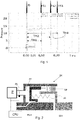
- the present invention relates to an agricultural vehicle AV equipped with a clutch BK equipped with a hydraulic circuit P for actuating it, in engagement or disengagement of the relative pack of discs DP.
- the hydraulic circuit drives a piston PT configured to pack at least a pair of friction discs DP.
- an spring SG opposes the packing to restore the opening of the clutch in depressurized conditions of the hydraulic circuit P.
- Closing the clutch involves the mechanical rotatably connection of the driver shaft PSH with the driven shaft SSH.
- a pressure sensor PS is installed on the circuit to convert a pressure signal into an electrical signal.
- a CPU processing unit is operationally connected with the PS sensor and acquire a pressure trend within the hydraulic circuit at least during the engagement and/or disengagement of the hydraulic clutch, see figure 2 .
- a sharp increase in pressure may correspond to the Dirac delta.
- the pulses FS1, FS2, F3 are represented in the figures. These pulses represent an event that interrupts the measurement of the amplitude TH1, TH2, TH3, etc. of a time interval that begins approximately when the command to activate (or deactivate) the clutch BK is activated.
- the event that causes the start of the measurement of the amplitude of the time interval corresponds to the activation of the hydraulic control or to the corresponding IS divergence of the derivative of the pressure signal.
- the engagement command is electro-actuated by means of a valve that has its own inertia and therefore a fairly stable delay with respect to the activation of the command. Therefore, it is equivalent to start the measurement of the aforementioned amplitude of the time interval when the activation signal, electric, is detected or when, a few tenths of seconds later, the first IS spike occurs.
- the plateau pattern is a primary feature of the hydraulic circuit.
- the mobile piston designed to compress the friction elements of the clutch BK is moved by the pumping of hydraulic fluid, generally hydraulic oil, with a limited power proportional to the flow rate for the generated pressure.
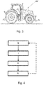
- the monitoring method object of the present invention provides for the execution in succession (see figure 4 ):
- the threshold TH1 can be determined for example as the average of time interval amplitudes acquired on a sample of agricultural vehicles equipped with a new clutch, or it can be determined as the average of time interval amplitudes acquired on the same vehicle during the first engagements (or disengages) of the clutch. For this reason, this threshold TH1 is indicated with a similar notation with respect to the amplitude of the monitored time interval to determine the state of wear of the clutch.
- the present invention can advantageously be carried out by means of a computer program which comprises coding means for the realization of one or more steps of the method, when this program is executed on a computer. Therefore, it is understood that the scope of protection extends to said computer program and further to computer readable means which comprise a recorded message, said computer readable means comprising program coding means for carrying out one or more steps of the method, when said program is run on a computer.
Landscapes
- Engineering & Computer Science (AREA)
- General Engineering & Computer Science (AREA)
- Physics & Mathematics (AREA)
- Fluid Mechanics (AREA)
- Mechanical Engineering (AREA)
- Hydraulic Clutches, Magnetic Clutches, Fluid Clutches, And Fluid Joints (AREA)
- Mechanical Operated Clutches (AREA)
Abstract
Description
- The present invention relates to a method of diagnosing the wear of a hydraulic clutch of a vehicle transmission comprising a pack of discs and more precisely of an agricultural vehicle.
- There are methods of estimating the wear of a hydraulic clutch which is based on the measurement of the energy passed through the same organ, especially during the closing phases of the clutch itself.
- It is believed that this method is not reliable as there are too many approximations and it is not easy to verify the fulfilment of the optimal conditions for monitoring.
- In fact, it is necessary to know the gear ratio, the mass of the vehicle and the inclination of the ground.
- In the field of agricultural vehicles, the clutch of the transmission is made by means of a pack of discs, in which an input of the disc pack is connected to a first part of the transmission and an input opposite the first is connected to the wheels and/or to a load in general.
- Therefore, the packing of the disc pack determines the interconnection of a first portion of the vehicle transmission with respect to a second portion of the same transmission.
- If not specifically excluded in the detailed description that follows, what is described in this chapter is to be considered as an integral part of the detailed description.
- The object of the present invention is to propose a method for monitoring the state of wear of a hydraulic clutch.
- The basic idea of the present invention is to monitor a pressure derivative in the piston actuation circuit that acts on the hydraulic clutch, measuring the time interval between a first instant, corresponding to the activation of the clutch engagement command hydraulic, and a second instant in which the pressure derivative assumes a second divergent trend.
- Indeed, it has been discovered that in hydraulic drive systems, immediately after the activation of the clutch engagement command, there is a rapid increase of the pressure in the control circuit of the actuating piston, then a plateau corresponding to the displacement of the piston and a further rapid increase in pressure corresponding to the compression of the pack of discs that define the clutch or the piston end of the sliding displacement.
- An electrical signal is associated with the pressure measurement. A processing unit calculates the derivative of the pressure measured in the piston actuation circuit and calculates a time interval that elapses between the first instant and the second instant. A gradual lengthening of the aforementioned interval indicates a gradual deterioration of the state of wear of the hydraulic clutch of the vehicle transmission.
- Advantageously, the present method of measurement is independent of any hypothesis about the conditions of inflation of the wheels, the loading and inclination conditions of the vehicle.
- The first instant is associated with the switching of a hydraulic circuit control switch or with a first divergent trend of the pressure derivative.
- It has been discovered that the first divergent trend of the pressure derivative occurs after a fixed time interval from the switching of the hydraulic circuit activation command. Therefore, thanks to this discovery it has been understood that for the purpose of assessing the lengthening of the monitored time interval, it is irrelevant to detect the instant of activation of the hydraulic control activation command or the corresponding first divergence event of the pressure derivative.
- The present invention finds application in the field of hydraulic clutches both in the case in which the clutch is engaged by compression by the hydraulic piston, and in the case in which the compression is performed by a spring, while the piston acts to disengage the clutch.
- The dependent claims describe preferred variants of the invention, forming an integral part of this description.
- Further objects and advantages of the present invention will become clear from the detailed description that follows of an example of embodiment of the same (and of its variants) and from the attached drawings given purely for explanatory and non-limiting purposes, in which:
-
Figure 1 shows a trend of the pressures as the state of wear of a hydraulic clutch of a vehicular transmission of a modified agricultural vehicle according to the method of the present invention; -
Figure 2 shows an example of a driving circuit of a hydraulic clutch of a vehicle transmission, in particular of a modified agricultural vehicle according to the present invention; -
Figure 3 shows an agricultural vehicle in which the hydraulic clutch ofFigure 2 and the monitoring method of the present invention is implemented; -
Figure 4 shows an exemplary flowchart of the method of the present invention, performed at an activation and/or deactivation of the hydraulic clutch. - The same numbers and the same reference letters in the figures identify the same elements or components.
- In the context of this description, the term "second" component does not imply the presence of a "first" component. These terms are indeed used as labels to improve clarity and should not be intended as limiting.
- The elements and characteristics illustrated in the various preferred embodiments, including the drawings, can be combined with each other without, however, leaving the scope of the protection of the present application as described below.
- The present invention, with reference to
Figures 2 and3 , relates to an agricultural vehicle AV equipped with a clutch BK equipped with a hydraulic circuit P for actuating it, in engagement or disengagement of the relative pack of discs DP. - In particular, the hydraulic circuit drives a piston PT configured to pack at least a pair of friction discs DP. Preferably, an spring SG opposes the packing to restore the opening of the clutch in depressurized conditions of the hydraulic circuit P.
- Closing the clutch involves the mechanical rotatably connection of the driver shaft PSH with the driven shaft SSH.
- A pressure sensor PS is installed on the circuit to convert a pressure signal into an electrical signal.
- A CPU processing unit is operationally connected with the PS sensor and acquire a pressure trend within the hydraulic circuit at least during the engagement and/or disengagement of the hydraulic clutch, see
figure 2 . - With reference to
figure 1 , it has been observed that when the clutch is engaged (or disengaged), there is a sharp increase in pressure. Subsequently, during the displacement of the piston, the pressure remains approximately constant, defining a so-called plateau. When the piston acting on the pack of discs compresses it (or releases it), there is a further sharp increase in pressure. - In terms of derivative, a sharp increase in pressure may correspond to the Dirac delta.
- Therefore, the pulses FS1, FS2, F3 are represented in the figures. These pulses represent an event that interrupts the measurement of the amplitude TH1, TH2, TH3, etc. of a time interval that begins approximately when the command to activate (or deactivate) the clutch BK is activated. According to the present invention, the event that causes the start of the measurement of the amplitude of the time interval corresponds to the activation of the hydraulic control or to the corresponding IS divergence of the derivative of the pressure signal.
- Generally, the engagement command is electro-actuated by means of a valve that has its own inertia and therefore a fairly stable delay with respect to the activation of the command. Therefore, it is equivalent to start the measurement of the aforementioned amplitude of the time interval when the activation signal, electric, is detected or when, a few tenths of seconds later, the first IS spike occurs.
- The plateau pattern is a primary feature of the hydraulic circuit. In fact, the mobile piston designed to compress the friction elements of the clutch BK is moved by the pumping of hydraulic fluid, generally hydraulic oil, with a limited power proportional to the flow rate for the generated pressure.
- Therefore, the monitoring method object of the present invention provides for the execution in succession (see
figure 4 ): - i a first step of acquiring, on the occasion of the engagement (or disengagement) of the hydraulic clutch, a derivative of a signal representative of a pressure in a relative clutch actuation circuit,
- ii a second step of measuring a time interval TH2, TH3, etc .. elapsing between the first instant IS, corresponding to the activation of the clutch engagement command, and a second instant FS1, FS2, FS3, etc. wherein the pressure derivative assumes a second divergent trend and
- iii a third step of comparing the time interval TH2, TH3, etc .. with a predetermined TH1 threshold.
- The threshold TH1 can be determined for example as the average of time interval amplitudes acquired on a sample of agricultural vehicles equipped with a new clutch, or it can be determined as the average of time interval amplitudes acquired on the same vehicle during the first engagements (or disengages) of the clutch. For this reason, this threshold TH1 is indicated with a similar notation with respect to the amplitude of the monitored time interval to determine the state of wear of the clutch.
- The present invention can advantageously be carried out by means of a computer program which comprises coding means for the realization of one or more steps of the method, when this program is executed on a computer. Therefore, it is understood that the scope of protection extends to said computer program and further to computer readable means which comprise a recorded message, said computer readable means comprising program coding means for carrying out one or more steps of the method, when said program is run on a computer.
- Implementing variations to the non-limiting example described are possible, without however departing from the scope of protection of the present invention, including all the equivalent realizations for a person skilled in the art, from the content of the claims.
- From the above description, the skilled in the art is able to realize the object of the invention without introduction of further details.
Claims (8)
- Method for wear monitoring of a hydraulic clutch (BK) of a vehicular driveline (PSH, SSH) comprising in succession (i) a first step of acquiring, at engagement and/or disengagement of the hydraulic clutch, a derivative of a signal representative of a pressure in a corresponding actuation circuit (P) of the hydraulic clutch, (ii) a second step of measurement of a time interval (TH2, TH3, etc..) elapsing between a first instant (IS), corresponding to the activation of the engagement command of the clutch, and a second instant (FS1, FS2, FS3) wherein the derivative of said signal assumes a second divergent trend and (iii) a third step of comparing said time interval (TH2, TH3, etc..) with a predetermined threshold (TH1).
- Method according to claim 1, comprising a preliminary step of setting as a predetermined threshold (TH1) said time interval obtained by means of a first preliminary execution of the first and second steps, namely when the clutch is new.
- Method according to any one of claims 1 or 2, wherein the first instant (IS) is associated with the switching of a control switch of the hydraulic circuit or with a first divergent trend of the derivative of the signal representative of the pressure.
- Method according to claim 3, wherein said derivative is calculated by implementing a processing unit suitably configured to acquire at least said signal representative of the pressure.
- Computer program comprising program coding means suitable for carrying out all steps (i - iii) of any one of claims 1 to 4, when said program is run on a computer.
- Computer readable means comprising a recorded program, said computer readable means comprising program coding means suitable for carrying out all steps (i - iii) of any one of claims 1 to 4, when said program is run on a computer.
- Wear monitoring system of a hydraulic clutch of a vehicle transmission comprising- a pressure sensor associated with a hydraulic circuit for operating the hydraulic clutch,- a processing unit operatively connected with the pressure sensor and configured to carry out all the steps of any one of claims 1 to 4.
- Agricultural vehicle (AV) comprising a hydraulic clutch of a related vehicle transmission and equipped with a hydraulic clutch wear monitoring system according to claim 7 .
Applications Claiming Priority (1)
| Application Number | Priority Date | Filing Date | Title |
|---|---|---|---|
| IT102020000011818A IT202000011818A1 (en) | 2020-05-21 | 2020-05-21 | Wear monitoring system of a hydraulic clutch of a vehicle transmission |
Publications (2)
| Publication Number | Publication Date |
|---|---|
| EP3913251A1 true EP3913251A1 (en) | 2021-11-24 |
| EP3913251B1 EP3913251B1 (en) | 2024-02-07 |
Family
ID=71784586
Family Applications (1)
| Application Number | Title | Priority Date | Filing Date |
|---|---|---|---|
| EP21174958.5A Active EP3913251B1 (en) | 2020-05-21 | 2021-05-20 | Method, computer program and system for wear monitoring of a hydraulic clutch of a vehicular driveline |
Country Status (2)
| Country | Link |
|---|---|
| EP (1) | EP3913251B1 (en) |
| IT (1) | IT202000011818A1 (en) |
Cited By (1)
| Publication number | Priority date | Publication date | Assignee | Title |
|---|---|---|---|---|
| EP4268563A1 (en) | 2022-04-27 | 2023-11-01 | CLAAS Selbstfahrende Erntemaschinen GmbH | Method for determining a wear state of an autonomous agricultural machine |
Citations (3)
| Publication number | Priority date | Publication date | Assignee | Title |
|---|---|---|---|---|
| US6117048A (en) * | 1996-04-10 | 2000-09-12 | Komatsu Ltd. | Apparatus and method for detecting abrasion of clutch for transmission |
| US20180172092A1 (en) * | 2016-12-15 | 2018-06-21 | Hyundai Motor Company | Touch point learning apparatus and method for clutch |
| DE102017202080A1 (en) * | 2017-02-09 | 2018-08-09 | Zf Friedrichshafen Ag | Method for real-time monitoring of an electrofluidically actuated friction clutch and / or friction brake |
-
2020
- 2020-05-21 IT IT102020000011818A patent/IT202000011818A1/en unknown
-
2021
- 2021-05-20 EP EP21174958.5A patent/EP3913251B1/en active Active
Patent Citations (3)
| Publication number | Priority date | Publication date | Assignee | Title |
|---|---|---|---|---|
| US6117048A (en) * | 1996-04-10 | 2000-09-12 | Komatsu Ltd. | Apparatus and method for detecting abrasion of clutch for transmission |
| US20180172092A1 (en) * | 2016-12-15 | 2018-06-21 | Hyundai Motor Company | Touch point learning apparatus and method for clutch |
| DE102017202080A1 (en) * | 2017-02-09 | 2018-08-09 | Zf Friedrichshafen Ag | Method for real-time monitoring of an electrofluidically actuated friction clutch and / or friction brake |
Cited By (2)
| Publication number | Priority date | Publication date | Assignee | Title |
|---|---|---|---|---|
| EP4268563A1 (en) | 2022-04-27 | 2023-11-01 | CLAAS Selbstfahrende Erntemaschinen GmbH | Method for determining a wear state of an autonomous agricultural machine |
| DE102022110117A1 (en) | 2022-04-27 | 2023-11-02 | Claas Selbstfahrende Erntemaschinen Gmbh | Method for determining a wear condition of an autonomous agricultural machine |
Also Published As
| Publication number | Publication date |
|---|---|
| IT202000011818A1 (en) | 2021-11-21 |
| EP3913251B1 (en) | 2024-02-07 |
Similar Documents
| Publication | Publication Date | Title |
|---|---|---|
| US6849027B2 (en) | Method and apparatus for diagnosing a malfunction of a clutch actuator | |
| US9511757B2 (en) | Method for determining a failure in a service or parking brake in a vehicle, regulating or control unit for carrying out the method, and parking brake having such a regulating or control unit | |
| CN1715110B (en) | Method for protecting automatically operated clutch of motor vehicle from overload | |
| KR100708019B1 (en) | Method for operating a vehicle. | |
| CN103477108B (en) | Method for commissioning the clutch | |
| KR20120052926A (en) | Fault detection and mitigation in hybrid drive system | |
| CN103975173B (en) | hydraulic operating system | |
| EP3913251B1 (en) | Method, computer program and system for wear monitoring of a hydraulic clutch of a vehicular driveline | |
| US5982280A (en) | Monitoring a clutch | |
| EP3184383A1 (en) | Staged method to detect brake fail conditions in brake control systems | |
| EP4326586A1 (en) | A method and a device for estimating residual torque between the braked and braking elements of a vehicle | |
| CN110701213B (en) | Clutch fault diagnosis method and device, electronic equipment and storage medium | |
| US11084474B2 (en) | Method for controlling a separating clutch | |
| EP3912875B1 (en) | Method and system for wear monitoring of a hydraulic parking brake | |
| CN110462244A (en) | Method for determining the service life of a friction clutch of a vehicle | |
| US20080015758A1 (en) | Process for monitoring the direction of frictional drive from a vehicle transmission at near-zero vehicle speed | |
| US20250178578A1 (en) | Spring brake actuators and apparatuses thereof | |
| JP6322728B2 (en) | Method for controlling clutch, computer program, computer-readable medium and control device | |
| CN107559351B (en) | Method for monitoring a friction clutch having at least two clutch disks that are in contact with one another | |
| KR101516886B1 (en) | A control device for assisting hill start of a car and method thereof | |
| JP5812359B2 (en) | Brake diagnostic device for machine press | |
| CN108799360B (en) | Method for determining the condition of a clutch | |
| CN102372003A (en) | Method for detecting the clutch condition | |
| KR102532020B1 (en) | Protection method for hydrostatic clutch actuators, especially for vehicles | |
| RU2577406C2 (en) | Diagnostics of mechanical engagement between vehicle first and second wheel axles |
Legal Events
| Date | Code | Title | Description |
|---|---|---|---|
| PUAI | Public reference made under article 153(3) epc to a published international application that has entered the european phase |
Free format text: ORIGINAL CODE: 0009012 |
|
| STAA | Information on the status of an ep patent application or granted ep patent |
Free format text: STATUS: THE APPLICATION HAS BEEN PUBLISHED |
|
| AK | Designated contracting states |
Kind code of ref document: A1 Designated state(s): AL AT BE BG CH CY CZ DE DK EE ES FI FR GB GR HR HU IE IS IT LI LT LU LV MC MK MT NL NO PL PT RO RS SE SI SK SM TR |
|
| B565 | Issuance of search results under rule 164(2) epc |
Effective date: 20211011 |
|
| STAA | Information on the status of an ep patent application or granted ep patent |
Free format text: STATUS: REQUEST FOR EXAMINATION WAS MADE |
|
| 17P | Request for examination filed |
Effective date: 20220524 |
|
| RBV | Designated contracting states (corrected) |
Designated state(s): AL AT BE BG CH CY CZ DE DK EE ES FI FR GB GR HR HU IE IS IT LI LT LU LV MC MK MT NL NO PL PT RO RS SE SI SK SM TR |
|
| RAP3 | Party data changed (applicant data changed or rights of an application transferred) |
Owner name: CNH INDUSTRIAL ITALIA S.P.A. |
|
| GRAP | Despatch of communication of intention to grant a patent |
Free format text: ORIGINAL CODE: EPIDOSNIGR1 |
|
| STAA | Information on the status of an ep patent application or granted ep patent |
Free format text: STATUS: GRANT OF PATENT IS INTENDED |
|
| INTG | Intention to grant announced |
Effective date: 20230904 |
|
| GRAS | Grant fee paid |
Free format text: ORIGINAL CODE: EPIDOSNIGR3 |
|
| GRAA | (expected) grant |
Free format text: ORIGINAL CODE: 0009210 |
|
| STAA | Information on the status of an ep patent application or granted ep patent |
Free format text: STATUS: THE PATENT HAS BEEN GRANTED |
|
| AK | Designated contracting states |
Kind code of ref document: B1 Designated state(s): AL AT BE BG CH CY CZ DE DK EE ES FI FR GB GR HR HU IE IS IT LI LT LU LV MC MK MT NL NO PL PT RO RS SE SI SK SM TR |
|
| REG | Reference to a national code |
Ref country code: GB Ref legal event code: FG4D |
|
| REG | Reference to a national code |
Ref country code: CH Ref legal event code: EP |
|
| REG | Reference to a national code |
Ref country code: IE Ref legal event code: FG4D |
|
| REG | Reference to a national code |
Ref country code: DE Ref legal event code: R096 Ref document number: 602021009150 Country of ref document: DE |
|
| REG | Reference to a national code |
Ref country code: LT Ref legal event code: MG9D |
|
| REG | Reference to a national code |
Ref country code: NL Ref legal event code: MP Effective date: 20240207 |
|
| PG25 | Lapsed in a contracting state [announced via postgrant information from national office to epo] |
Ref country code: IS Free format text: LAPSE BECAUSE OF FAILURE TO SUBMIT A TRANSLATION OF THE DESCRIPTION OR TO PAY THE FEE WITHIN THE PRESCRIBED TIME-LIMIT Effective date: 20240607 |
|
| PG25 | Lapsed in a contracting state [announced via postgrant information from national office to epo] |
Ref country code: LT Free format text: LAPSE BECAUSE OF FAILURE TO SUBMIT A TRANSLATION OF THE DESCRIPTION OR TO PAY THE FEE WITHIN THE PRESCRIBED TIME-LIMIT Effective date: 20240207 |
|
| PG25 | Lapsed in a contracting state [announced via postgrant information from national office to epo] |
Ref country code: GR Free format text: LAPSE BECAUSE OF FAILURE TO SUBMIT A TRANSLATION OF THE DESCRIPTION OR TO PAY THE FEE WITHIN THE PRESCRIBED TIME-LIMIT Effective date: 20240508 |
|
| REG | Reference to a national code |
Ref country code: AT Ref legal event code: MK05 Ref document number: 1655566 Country of ref document: AT Kind code of ref document: T Effective date: 20240207 |
|
| PG25 | Lapsed in a contracting state [announced via postgrant information from national office to epo] |
Ref country code: RS Free format text: LAPSE BECAUSE OF FAILURE TO SUBMIT A TRANSLATION OF THE DESCRIPTION OR TO PAY THE FEE WITHIN THE PRESCRIBED TIME-LIMIT Effective date: 20240507 Ref country code: HR Free format text: LAPSE BECAUSE OF FAILURE TO SUBMIT A TRANSLATION OF THE DESCRIPTION OR TO PAY THE FEE WITHIN THE PRESCRIBED TIME-LIMIT Effective date: 20240207 Ref country code: NL Free format text: LAPSE BECAUSE OF FAILURE TO SUBMIT A TRANSLATION OF THE DESCRIPTION OR TO PAY THE FEE WITHIN THE PRESCRIBED TIME-LIMIT Effective date: 20240207 |
|
| PG25 | Lapsed in a contracting state [announced via postgrant information from national office to epo] |
Ref country code: ES Free format text: LAPSE BECAUSE OF FAILURE TO SUBMIT A TRANSLATION OF THE DESCRIPTION OR TO PAY THE FEE WITHIN THE PRESCRIBED TIME-LIMIT Effective date: 20240207 |
|
| PG25 | Lapsed in a contracting state [announced via postgrant information from national office to epo] |
Ref country code: AT Free format text: LAPSE BECAUSE OF FAILURE TO SUBMIT A TRANSLATION OF THE DESCRIPTION OR TO PAY THE FEE WITHIN THE PRESCRIBED TIME-LIMIT Effective date: 20240207 |
|
| PG25 | Lapsed in a contracting state [announced via postgrant information from national office to epo] |
Ref country code: RS Free format text: LAPSE BECAUSE OF FAILURE TO SUBMIT A TRANSLATION OF THE DESCRIPTION OR TO PAY THE FEE WITHIN THE PRESCRIBED TIME-LIMIT Effective date: 20240507 Ref country code: NO Free format text: LAPSE BECAUSE OF FAILURE TO SUBMIT A TRANSLATION OF THE DESCRIPTION OR TO PAY THE FEE WITHIN THE PRESCRIBED TIME-LIMIT Effective date: 20240507 Ref country code: NL Free format text: LAPSE BECAUSE OF FAILURE TO SUBMIT A TRANSLATION OF THE DESCRIPTION OR TO PAY THE FEE WITHIN THE PRESCRIBED TIME-LIMIT Effective date: 20240207 Ref country code: LT Free format text: LAPSE BECAUSE OF FAILURE TO SUBMIT A TRANSLATION OF THE DESCRIPTION OR TO PAY THE FEE WITHIN THE PRESCRIBED TIME-LIMIT Effective date: 20240207 Ref country code: IS Free format text: LAPSE BECAUSE OF FAILURE TO SUBMIT A TRANSLATION OF THE DESCRIPTION OR TO PAY THE FEE WITHIN THE PRESCRIBED TIME-LIMIT Effective date: 20240607 Ref country code: HR Free format text: LAPSE BECAUSE OF FAILURE TO SUBMIT A TRANSLATION OF THE DESCRIPTION OR TO PAY THE FEE WITHIN THE PRESCRIBED TIME-LIMIT Effective date: 20240207 Ref country code: GR Free format text: LAPSE BECAUSE OF FAILURE TO SUBMIT A TRANSLATION OF THE DESCRIPTION OR TO PAY THE FEE WITHIN THE PRESCRIBED TIME-LIMIT Effective date: 20240508 Ref country code: FI Free format text: LAPSE BECAUSE OF FAILURE TO SUBMIT A TRANSLATION OF THE DESCRIPTION OR TO PAY THE FEE WITHIN THE PRESCRIBED TIME-LIMIT Effective date: 20240207 Ref country code: ES Free format text: LAPSE BECAUSE OF FAILURE TO SUBMIT A TRANSLATION OF THE DESCRIPTION OR TO PAY THE FEE WITHIN THE PRESCRIBED TIME-LIMIT Effective date: 20240207 Ref country code: BG Free format text: LAPSE BECAUSE OF FAILURE TO SUBMIT A TRANSLATION OF THE DESCRIPTION OR TO PAY THE FEE WITHIN THE PRESCRIBED TIME-LIMIT Effective date: 20240207 Ref country code: AT Free format text: LAPSE BECAUSE OF FAILURE TO SUBMIT A TRANSLATION OF THE DESCRIPTION OR TO PAY THE FEE WITHIN THE PRESCRIBED TIME-LIMIT Effective date: 20240207 |
|
| PG25 | Lapsed in a contracting state [announced via postgrant information from national office to epo] |
Ref country code: PL Free format text: LAPSE BECAUSE OF FAILURE TO SUBMIT A TRANSLATION OF THE DESCRIPTION OR TO PAY THE FEE WITHIN THE PRESCRIBED TIME-LIMIT Effective date: 20240207 Ref country code: PT Free format text: LAPSE BECAUSE OF FAILURE TO SUBMIT A TRANSLATION OF THE DESCRIPTION OR TO PAY THE FEE WITHIN THE PRESCRIBED TIME-LIMIT Effective date: 20240607 |
|
| PG25 | Lapsed in a contracting state [announced via postgrant information from national office to epo] |
Ref country code: SE Free format text: LAPSE BECAUSE OF FAILURE TO SUBMIT A TRANSLATION OF THE DESCRIPTION OR TO PAY THE FEE WITHIN THE PRESCRIBED TIME-LIMIT Effective date: 20240207 Ref country code: PT Free format text: LAPSE BECAUSE OF FAILURE TO SUBMIT A TRANSLATION OF THE DESCRIPTION OR TO PAY THE FEE WITHIN THE PRESCRIBED TIME-LIMIT Effective date: 20240607 Ref country code: PL Free format text: LAPSE BECAUSE OF FAILURE TO SUBMIT A TRANSLATION OF THE DESCRIPTION OR TO PAY THE FEE WITHIN THE PRESCRIBED TIME-LIMIT Effective date: 20240207 Ref country code: LV Free format text: LAPSE BECAUSE OF FAILURE TO SUBMIT A TRANSLATION OF THE DESCRIPTION OR TO PAY THE FEE WITHIN THE PRESCRIBED TIME-LIMIT Effective date: 20240207 |
|
| PG25 | Lapsed in a contracting state [announced via postgrant information from national office to epo] |
Ref country code: DK Free format text: LAPSE BECAUSE OF FAILURE TO SUBMIT A TRANSLATION OF THE DESCRIPTION OR TO PAY THE FEE WITHIN THE PRESCRIBED TIME-LIMIT Effective date: 20240207 |
|
| PG25 | Lapsed in a contracting state [announced via postgrant information from national office to epo] |
Ref country code: SM Free format text: LAPSE BECAUSE OF FAILURE TO SUBMIT A TRANSLATION OF THE DESCRIPTION OR TO PAY THE FEE WITHIN THE PRESCRIBED TIME-LIMIT Effective date: 20240207 |
|
| PG25 | Lapsed in a contracting state [announced via postgrant information from national office to epo] |
Ref country code: CZ Free format text: LAPSE BECAUSE OF FAILURE TO SUBMIT A TRANSLATION OF THE DESCRIPTION OR TO PAY THE FEE WITHIN THE PRESCRIBED TIME-LIMIT Effective date: 20240207 Ref country code: EE Free format text: LAPSE BECAUSE OF FAILURE TO SUBMIT A TRANSLATION OF THE DESCRIPTION OR TO PAY THE FEE WITHIN THE PRESCRIBED TIME-LIMIT Effective date: 20240207 |
|
| PG25 | Lapsed in a contracting state [announced via postgrant information from national office to epo] |
Ref country code: SK Free format text: LAPSE BECAUSE OF FAILURE TO SUBMIT A TRANSLATION OF THE DESCRIPTION OR TO PAY THE FEE WITHIN THE PRESCRIBED TIME-LIMIT Effective date: 20240207 |
|
| PG25 | Lapsed in a contracting state [announced via postgrant information from national office to epo] |
Ref country code: SM Free format text: LAPSE BECAUSE OF FAILURE TO SUBMIT A TRANSLATION OF THE DESCRIPTION OR TO PAY THE FEE WITHIN THE PRESCRIBED TIME-LIMIT Effective date: 20240207 Ref country code: SK Free format text: LAPSE BECAUSE OF FAILURE TO SUBMIT A TRANSLATION OF THE DESCRIPTION OR TO PAY THE FEE WITHIN THE PRESCRIBED TIME-LIMIT Effective date: 20240207 Ref country code: RO Free format text: LAPSE BECAUSE OF FAILURE TO SUBMIT A TRANSLATION OF THE DESCRIPTION OR TO PAY THE FEE WITHIN THE PRESCRIBED TIME-LIMIT Effective date: 20240207 Ref country code: EE Free format text: LAPSE BECAUSE OF FAILURE TO SUBMIT A TRANSLATION OF THE DESCRIPTION OR TO PAY THE FEE WITHIN THE PRESCRIBED TIME-LIMIT Effective date: 20240207 Ref country code: DK Free format text: LAPSE BECAUSE OF FAILURE TO SUBMIT A TRANSLATION OF THE DESCRIPTION OR TO PAY THE FEE WITHIN THE PRESCRIBED TIME-LIMIT Effective date: 20240207 Ref country code: CZ Free format text: LAPSE BECAUSE OF FAILURE TO SUBMIT A TRANSLATION OF THE DESCRIPTION OR TO PAY THE FEE WITHIN THE PRESCRIBED TIME-LIMIT Effective date: 20240207 |
|
| REG | Reference to a national code |
Ref country code: DE Ref legal event code: R097 Ref document number: 602021009150 Country of ref document: DE |
|
| PLBE | No opposition filed within time limit |
Free format text: ORIGINAL CODE: 0009261 |
|
| STAA | Information on the status of an ep patent application or granted ep patent |
Free format text: STATUS: NO OPPOSITION FILED WITHIN TIME LIMIT |
|
| REG | Reference to a national code |
Ref country code: CH Ref legal event code: PL |
|
| PG25 | Lapsed in a contracting state [announced via postgrant information from national office to epo] |
Ref country code: MC Free format text: LAPSE BECAUSE OF FAILURE TO SUBMIT A TRANSLATION OF THE DESCRIPTION OR TO PAY THE FEE WITHIN THE PRESCRIBED TIME-LIMIT Effective date: 20240207 |
|
| 26N | No opposition filed |
Effective date: 20241108 |
|
| PG25 | Lapsed in a contracting state [announced via postgrant information from national office to epo] |
Ref country code: LU Free format text: LAPSE BECAUSE OF NON-PAYMENT OF DUE FEES Effective date: 20240520 |
|
| PG25 | Lapsed in a contracting state [announced via postgrant information from national office to epo] |
Ref country code: MC Free format text: LAPSE BECAUSE OF FAILURE TO SUBMIT A TRANSLATION OF THE DESCRIPTION OR TO PAY THE FEE WITHIN THE PRESCRIBED TIME-LIMIT Effective date: 20240207 Ref country code: LU Free format text: LAPSE BECAUSE OF NON-PAYMENT OF DUE FEES Effective date: 20240520 Ref country code: CH Free format text: LAPSE BECAUSE OF NON-PAYMENT OF DUE FEES Effective date: 20240531 |
|
| REG | Reference to a national code |
Ref country code: BE Ref legal event code: MM Effective date: 20240531 |
|
| PG25 | Lapsed in a contracting state [announced via postgrant information from national office to epo] |
Ref country code: IE Free format text: LAPSE BECAUSE OF NON-PAYMENT OF DUE FEES Effective date: 20240520 |
|
| PG25 | Lapsed in a contracting state [announced via postgrant information from national office to epo] |
Ref country code: SI Free format text: LAPSE BECAUSE OF FAILURE TO SUBMIT A TRANSLATION OF THE DESCRIPTION OR TO PAY THE FEE WITHIN THE PRESCRIBED TIME-LIMIT Effective date: 20240207 Ref country code: BE Free format text: LAPSE BECAUSE OF NON-PAYMENT OF DUE FEES Effective date: 20240531 |
|
| PGFP | Annual fee paid to national office [announced via postgrant information from national office to epo] |
Ref country code: DE Payment date: 20250528 Year of fee payment: 5 |
|
| PGFP | Annual fee paid to national office [announced via postgrant information from national office to epo] |
Ref country code: GB Payment date: 20250520 Year of fee payment: 5 |
|
| PGFP | Annual fee paid to national office [announced via postgrant information from national office to epo] |
Ref country code: IT Payment date: 20250522 Year of fee payment: 5 |
|
| PGFP | Annual fee paid to national office [announced via postgrant information from national office to epo] |
Ref country code: FR Payment date: 20250526 Year of fee payment: 5 |
|
| PG25 | Lapsed in a contracting state [announced via postgrant information from national office to epo] |
Ref country code: CY Free format text: LAPSE BECAUSE OF FAILURE TO SUBMIT A TRANSLATION OF THE DESCRIPTION OR TO PAY THE FEE WITHIN THE PRESCRIBED TIME-LIMIT; INVALID AB INITIO Effective date: 20210520 |
|
| PG25 | Lapsed in a contracting state [announced via postgrant information from national office to epo] |
Ref country code: HU Free format text: LAPSE BECAUSE OF FAILURE TO SUBMIT A TRANSLATION OF THE DESCRIPTION OR TO PAY THE FEE WITHIN THE PRESCRIBED TIME-LIMIT; INVALID AB INITIO Effective date: 20210520 |