EP3913240A1 - Captive fastener systems - Google Patents
Captive fastener systems Download PDFInfo
- Publication number
- EP3913240A1 EP3913240A1 EP21163921.6A EP21163921A EP3913240A1 EP 3913240 A1 EP3913240 A1 EP 3913240A1 EP 21163921 A EP21163921 A EP 21163921A EP 3913240 A1 EP3913240 A1 EP 3913240A1
- Authority
- EP
- European Patent Office
- Prior art keywords
- fastener
- captive
- captive fastener
- mounting
- sleeve
- Prior art date
- Legal status (The legal status is an assumption and is not a legal conclusion. Google has not performed a legal analysis and makes no representation as to the accuracy of the status listed.)
- Granted
Links
Images






Classifications
-
- F—MECHANICAL ENGINEERING; LIGHTING; HEATING; WEAPONS; BLASTING
- F16—ENGINEERING ELEMENTS AND UNITS; GENERAL MEASURES FOR PRODUCING AND MAINTAINING EFFECTIVE FUNCTIONING OF MACHINES OR INSTALLATIONS; THERMAL INSULATION IN GENERAL
- F16B—DEVICES FOR FASTENING OR SECURING CONSTRUCTIONAL ELEMENTS OR MACHINE PARTS TOGETHER, e.g. NAILS, BOLTS, CIRCLIPS, CLAMPS, CLIPS OR WEDGES; JOINTS OR JOINTING
- F16B41/00—Measures against loss of bolts, nuts, or pins; Measures against unauthorised operation of bolts, nuts or pins
- F16B41/002—Measures against loss of bolts, nuts or pins
-
- F—MECHANICAL ENGINEERING; LIGHTING; HEATING; WEAPONS; BLASTING
- F16—ENGINEERING ELEMENTS AND UNITS; GENERAL MEASURES FOR PRODUCING AND MAINTAINING EFFECTIVE FUNCTIONING OF MACHINES OR INSTALLATIONS; THERMAL INSULATION IN GENERAL
- F16B—DEVICES FOR FASTENING OR SECURING CONSTRUCTIONAL ELEMENTS OR MACHINE PARTS TOGETHER, e.g. NAILS, BOLTS, CIRCLIPS, CLAMPS, CLIPS OR WEDGES; JOINTS OR JOINTING
- F16B5/00—Joining sheets or plates, e.g. panels, to one another or to strips or bars parallel to them
- F16B5/02—Joining sheets or plates, e.g. panels, to one another or to strips or bars parallel to them by means of fastening members using screw-thread
- F16B5/0208—Joining sheets or plates, e.g. panels, to one another or to strips or bars parallel to them by means of fastening members using screw-thread using panel fasteners, i.e. permanent attachments allowing for quick assembly
Definitions
- the subject matter disclosed herein generally relates to fastener systems, and more specifically to captive fastener systems having increased float capabilities.
- Captive fasteners/captive fastener assemblies are a class of fastener designed for a permanent hold (captivation) within a target assembly or housing, including upon servicing.
- a captive fastener assembly By employing a captive fastener assembly, such systems can provide a secure joining, and avoid fastener loss or damage that might be caused by a loose part. That is, when two structures, which are joined by a captive fastener, are separated, the fastener that is captive remains with one of the two structures or otherwise secured such that the fastener is not loose.
- Examples of captive fasteners include threaded locking systems, press-fitting systems, or broaching systems to accomplish an anchor-hold within a larger assembly housing.
- captive fastener systems include a captive fastener assembly having a sleeve and a captive fastener arranged within the sleeve, a mounting assembly having a bushing and a mounting fastener arranged to pass through the bushing, and a joining body having a mounting aperture, wherein the sleeve is attached to the joining body and the bushing and the mounting fastener are configured to pass through the mounting aperture.
- the mounting assembly provides a first degree of movement of the captive fastener system and the captive fastener assembly provides a second degree of movement of the captive fastener system.
- further embodiments of the captive fastener systems may include that the sleeve includes an internal thread configured to enable the fastener to be secured within the sleeve by the internal thread.
- further embodiments of the captive fastener systems may include that the captive fastener comprises a shank having a diameter that is less than an internal surface of the internal thread to provide a float between the shank and the internal thread.
- further embodiments of the captive fastener systems may include that the captive fastener assembly includes a biasing element configured to provide a biasing force to the captive fastener.
- further embodiments of the captive fastener systems may include that the sleeve and the joining body are formed of a continuous material.
- further embodiments of the captive fastener systems may include that the sleeve is fixedly attached to the joining body.
- further embodiments of the captive fastener systems may include that the mounting fastener is configured to threadedly connect to a first structure and the captive fastener is configured to threadedly connect to a second structure to fixedly attach the first structure to the second structure.
- further embodiments of the captive fastener systems may include at least one additional captive fastener assembly having a respective sleeve and a respective captive fastener, wherein the sleeve of the at least one additional captive fastener assembly is attached to the joining body.
- further embodiments of the captive fastener systems may include at least one additional mounting assembly having a respective bushing and a respective mounting fastener, wherein the at least one additional mounting assembly is configured to pass through an additional mounting aperture of the joining body.
- further embodiments of the captive fastener systems may include that the captive fastener has a first end and a second end with a head arranged at the first end and a threaded portion at the second end.
- the structural assemblies include a first structure, a second structure, wherein the first structure is configured to be mounted to the second structure, and a captive fastener system configured to mount and connect the first structure to the second structure.
- the captive fastener system includes a captive fastener assembly having a sleeve and a captive fastener arranged within the sleeve, wherein the captive fastener is configured to threadedly engage with the second structure, a mounting assembly having a bushing and a mounting fastener arranged to pass through the bushing, wherein the mounting fastener is configured to threadedly engage with the first structure, and a joining body having a mounting aperture, wherein the sleeve is attached to the joining body and the bushing and the mounting fastener are configured to pass through the mounting aperture.
- the mounting assembly provides a first degree of movement of the captive fastener system and the captive fastener assembly provides a second degree of movement of the captive fastener system.
- further embodiments of the structural assemblies may include that the sleeve includes an internal thread configured to enable the fastener to be secured within the sleeve by the internal thread.
- further embodiments of the structural assemblies may include that the captive fastener comprises a shank having a diameter that is less than an internal surface of the internal thread to provide a float between the shank and the internal thread.
- further embodiments of the structural assemblies may include that the captive fastener assembly includes a biasing element configured to provide a biasing force to the captive fastener.
- further embodiments of the structural assemblies may include that the sleeve and the joining body are formed of a continuous material.
- further embodiments of the structural assemblies may include that the sleeve is fixedly attached to the joining body.
- further embodiments of the structural assemblies may include that the joining body defines an engagement surface that contacts and engages with the first structure.
- further embodiments of the structural assemblies may include at least one additional captive fastener assembly having a respective sleeve and a respective captive fastener, wherein the sleeve of the at least one additional captive fastener assembly is attached to the joining body.
- further embodiments of the structural assemblies may include at least one additional mounting assembly having a respective bushing and a respective mounting fastener, wherein the at least one additional mounting assembly is configured to pass through an additional mounting aperture of the joining body.
- further embodiments of the structural assemblies may include that the captive fastener has a first end and a second end with a head arranged at the first end and a threaded portion at the second end.
- the captive fastener assembly 100 is a system for joining and connecting a first structure 102 to a second structure 104 using a captive fastener 106.
- the captive fastener 106 is configured to securely and fixedly (but removably) attach the first structure 102 to the second structure 104.
- the captive fastener 106 is fixedly (and not removably) attached and connected to (e.g., part of) the first structure 102.
- the captive fastener 106 remains attached to the first structure 102. This is particularly useful when loose parts are a challenge or can be of concern (e.g., in low gravity environments).
- the captive fastener 106 includes a sleeve 108 that is configured to be fixedly and (optionally) permanently attached to the first structure 102, such as by bonding, welding, threaded connection, lock-and-key, etc., as will be appreciated by those of skill in the art.
- the sleeve 108 defines an internal bore or channel 110 through which a fastener 112 passes.
- the fastener 112 is movably retained within the channel 110 and is configured to not be easily separated from the sleeve 108.
- the fastener 112 includes a head 114 at a first end 116, a threaded portion 118 at a second end 120, and a body or shank 122 extending between and connecting the head 114 to the threaded portion 118.
- the sleeve 108 To retain the fastener 112 within the channel 110, the sleeve 108 includes an internal thread 124.
- the internal thread 124 extends radially inward from an internal surface of the channel 110 of the sleeve 108 a distance that is equal to an external radial outward extent of threads of the threaded potion 118 of the fastener 112. As such, translational movement of the fastener 112 to exit the sleeve 108 is prevented. That is, the internal threads 124 are configured to operate as a stop to secure and retain the fastener 112 within the sleeve 108.
- the internal thread 124 is a threaded structure that allows for the threaded portion 118 of the fastener 112 to be unthreaded and enables the fastener 112 to be completely removed from the sleeve 108.
- An optional biasing element 126 e.g., a spring may be provided between the internal thread 124 and the head 114 of the fastener 112.
- the fastener 112 When the fastener 112 is installed into the sleeve 108, but not yet engaged with the second structure 104, the fastener 112 has radial float 128.
- the radial float 128 is the space between an external surface of the shank 122 and the internal surface of the internal thread 124.
- the shank 122 has a reduced diameter as compared to the threaded portion 118 and the internal surface of the sleeve 108. This reduced diameter shank 122 allows for the fastener 112 to be adjusted in position when the first structure 102 is arranged proximate the second structure 104 and allows for slight adjustment or positioning of the fastener 112 to be threadedly engaged with a threaded hole of the second structure 104.
- the radial float 128 allows for positional compensation during installation and connection of the first structure 102 to the second structure 104.
- FIG. 2 a schematic illustration of a structural assembly 200 that has a first structure 202 connected to a second structure 204 by captive fasteners 206 is shown.
- Each captive fastener 206 is fixedly attached to a portion of the first structure 202, such as by welding, swaging, bonding, etc.
- the captive fasteners 206 include a fastener 208 installed through a sleeve 210 and locked or secured within the sleeve 210 by an internal thread 212 of the sleeve 210.
- the captive fasteners 206 have reduced diameter shanks 214 and threaded portions 216 configured to threadedly engage with a threaded hole 218 of the second structure 204.
- the first structure 202 includes two captive fasteners 206 which are fixed in position and configured to threadedly engage at two locations on the second structure 204.
- each captive fastener 206 is fixedly connected to the first structure 202 and the threaded holes 218 for installation of the second structure 204 are fixed, the tolerances permitted by such assemblies is very low.
- the radial float provided by the captive fasteners 206 allows for some variations for alignment of the first structure 202 relative to the second structure 204. If the first structure 202 and the second structure 204 are manufactured separately, there must be very accurate manufacturing to enable the respective components (e.g., captive fasteners 206 and threaded holes 218) to align and allow for the captive fasteners 206 to securely attach the first structure 202 to the second structure 204.
- captive fastener assemblies are provided that allow for increased tolerances between first and second structures while maintaining the captive nature of the fasteners and enabling secure joining and attachment of the first structure to the second structure.
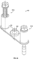
- FIGS. 3A-3C schematic illustrations of a captive fastener system 300 in accordance with an embodiment of the present disclosure are shown.
- FIG. 3A is an isometric illustration of the captive fastener system 300
- FIG. 3B is a side elevation view of the captive fastener system 300
- FIG. 3C is a cross-section, side elevation view of the captive fastener system 300.
- the captive fastener system 300 may be used to join two structures, similar to that described above, but allows for increased adjustment/tolerance with respect to aligning the two structures to be joined.
- the captive fastener system 300 is separated from and not part of or fixedly/permanently attached to one of the structures to be joined, but rather provides for an independent captive structure and system that enables a captive fastener without being captive to a specific assembly structure. Instead, the captive fastener system 300 is a separate component that is configured to attach, separately, to each of the first structure and the second structure, using different fasteners, as described herein.
- the captive fastener system 300 includes a captive fastener assembly 302, a mounting assembly 304, and a joining body 306.
- the captive fastener assembly 302 is fixedly connected to the joining body 306, whereas the mounting assembly 304 is not fixedly connected to the joining body 306.
- the captive fastener assembly 302 includes a sleeve 308, a captive fastener 310 having a shank 312, and a biasing element 314 configured to apply a biasing force to the captive fastener 310, as shown in FIGS. 3A-3C .
- the sleeve 308 includes an internal thread 316 within the sleeve 308 (shown in FIG. 3C ) and the captive fastener 310 includes a threaded portion 318.
- the threaded portion 318 is configured to threadedly pass through the internal thread 316 of the sleeve 308 to secure the captive fastener 310 within the sleeve 308.
- the sleeve 308 is an integral portion of the joining body 306 such that the sleeve 308 and the joining body are a single, continuous structure formed of a single or continuous material (e.g., as shown in FIG. 3B ).
- the sleeve 308 may be fixedly and permanently attached to the joining body 306 by various known means, such as welding, bodying, swaging, etc.
- the mounting assembly 304 includes a mounting fastener 320 and a bushing 322.
- the bushing 322 is arranged to movably sit within a mounting aperture 324 of the joining body 306.
- the mounting fastener 320 is configured to threadedly engage with a first structure and, when fully tightened, to secure the bushing 322 and the joining body 306 relative to the first structure.
- the joining body 306 has play or movement within the mounting aperture 324 between the joining body 306 and the bushing 322, which adds additional freedom of adjustment of the captive fastener system 300.
- FIGS. 4A-4C schematic illustrations of a captive fastener system 400 in accordance with an embodiment of the present disclosure are shown.
- FIG. 4a is an isometric illustration of the captive fastener system 400
- FIG. 4B is a side elevation view of the captive fastener system 400
- FIG. 4C is a cross-section, side elevation view of the captive fastener system 400.
- the captive fastener system 400 may be used to join two structures, similar to that described above, but allows for increased adjustment/tolerance with respect to aligning the two structures to be joined.
- the captive fastener system 400 may be similar to that of the captive fastener system 300 of FIGS. 3A-3C , but includes two captive fastener assemblies 402a, 402b that are joined to a mounting assembly 404 by a joining body 406.
- FIGS. 4A-4C is illustrative of an alternative configuration that illustrates that the number of captive fastener assemblies can be selected to a specific application and installation and is not limited to a single captive fastener assembly. Further, it will be appreciate that the number of mounting assemblies may be increased beyond a single mounting assembly.
- captive fastener system 500 includes four captive fastener assemblies 502a, 502b, 502c, 502d (i.e., at least one additional captive fastener assembly) and two mounting assemblies 504a, 504b (i.e., at least one additional mounting assembly) that are all connected by a joining body 506.
- FIG. 5 is also illustrative of the degrees of movement or freedom provided by the captive fastener systems of the present disclosure.
- the joining body 506 is movable about a primary axis Ao (e.g., left-right, up-down on the page of FIG. 5 ).
- the mounting assemblies 504a, 504b may be secured to the first structure to fix the relative positions of the captive fastener assemblies 502a, 502b, 502c, 502d.
- each of the fasteners of the respective captive fastener assemblies 502a, 502b, 502c, 502d may be moved relative to or about a respective captive fastener axis A a , A b , A c , A d to enable proper threading of the fasteners into the second structure and secure and attach the first structure to the second structure.
- the joining body 506 not only fixedly aligns/relates each of the captive fastener assemblies 502a, 502b, 502c, 502d but also can provide for an engagement surface to contact the first structure and apply a force thereto when the captive fasteners are threadedly connected to the second structure.
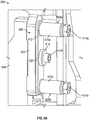
- FIGS. 6A-6B schematic illustrations of a structural assembly 600 that has a first structure 602 connected to a second structure 604 by a captive fastener system 606 in accordance with an embodiment of the present disclosure are shown.
- FIG. 6B is a cross-sectional view of the view of FIG. 6A .
- the captive fastener system 606 includes two captive fastener assemblies 608a, 608b (i.e., at least one additional captive fastener assembly), a mounting assembly 610, and a joining body 612 that connects the captive fastener assemblies 608a, 608b and the mounting assembly 610.
- Each captive fastener assembly 608a, 608b includes a respective captive fastener 614a, 614b installed through a respective sleeve 616a, 616b.
- the captive fastener assemblies 608a, 608b are configured to threadedly engage with the second structure 604 and the mounting assembly 610 is configured to threadedly engage with the first structure 602.
- the mounting assembly 610 includes a mounting fastener 618 and a bushing 620.
- the captive fastener system 606 may be positioned such that the mounting fastener 618 of the captive fastener system 606 is aligned with a threaded hole of the first structure 602.
- the mounting fastener 618 may be engaged slightly but allow for the entire captive fastener system 606 to move, and specifically, the joining body 612 may be adjusted to have the captive fasteners 614a, 614b to be substantially aligned with respective threaded holes of the second structure 604.
- the mounting fastener 618 may then be fully fastened and force the bushing 620 into contact with the joining body 612 and to secure the joining body 612 and the connected fastener assemblies 608a, 608b to the first structure 602.
- the joining body 612 may be moveable relative to the mounting fastener 618 and bushing 620.
- the captive fasteners 614a, 614b may be threadedly engaged with threaded holes of the second structure 604 and thus secure the first structure 602 to the second structure 604.
- the captive fastener system 700 includes captive fastener assemblies (not shown) that are attached to a joining body 702.
- the captive fastener system 700 includes a mounting assembly 704 that includes a mounting fastener 706 and a bushing 708.
- the bushing 708 is arranged to movably sit within a mounting aperture 710 of the joining body 702.
- the mounting fastener 706 is configured to threadedly engage with a first structure and, when fully tightened, to secure the bushing 708 and moveably secure the joining body 702 relative to the first structure. After fully tightening the mounting fastener 706, the joining body 702 has play or movement within the mounting aperture 710 between the joining body 702 and the bushing 708, which adds additional freedom of adjustment of the captive fastener system 700. For example, when the mounting fastener 706 is fully tightened, a contact surface 712 of the bushing 708 will contact a surface of the first structure to which the mounting fastener 706 engages. The joining body 702 is free to move about the bushing 708.
- the dimensions of the bushing 708 and the joining body 702 are appropriately set.
- the bushing 708 includes a captive surface 714 that is configured to be arranged relative to a retention surface 716 of the joining body 702 and prevent the joining body 702 from moving in an axial direction relative to the mounting fastener 706 by more than a limited amount.
- the joining body 702 When installed to a first structure, the joining body 702 has a respective contact surface 718 that contacts the first structure. As such, when installed, the contact surface 712 of the bushing 706 and the contact surface 718 of the joining body 702 will contact the first structure.
- the mounting fastener 706 and bushing 708 are not configured to fixedly secure the joining body 702 in place, but rather a limited amount of movement of the joining body 702 is provided.
- the bushing 708 has a bushing height H b that is defined between the contact surface 712 of the bushing 708 and the captive surface 714 of the bushing.
- the joining body 702 has a body thickness H j that is defined as the material thickness between the contact surface 718 of the joining body 702 and the retention surface 716 of the joining body 702.
- a bushing gap Gb is formed between the contact surface 714 of the bushing 708 and the retention surface 716 of the joining body 702. It will be appreciated that the bushing gap Gb may be implemented with any of the above described captive fastener systems of the present disclosure and variations thereof.
- embodiments of the present disclosure are directed to increased float captive fastener systems.
- the captive fastener systems of the present disclosure are not part of either structure of two joined structures, which enables an additional degree of movement or freedom for adjusting parts relative to each other.
- the captive fastener systems maintain the existing radial float between the captive fastener and the sleeve but adds an additional degree of float by allowing the sleeve to float relative to a structure as well. This additional float is not dependent on the captive fastener size and can be tailored to specific applications and configurations.
- a first degree of float is provided between a reduced shank of a captive fastener and the inner diameter/surface of the internal thread in the sleeve.
- a second degree of float is provided at the mounting assembly with the bushing that engages with the joining body which includes the sleeve(s) of the captive fastener assemblies and allows for additional float by providing a clearance between the bushing outside diameter and the inside diameter of the hole in the joining body.
- embodiments of the present disclosure provide for captive fasteners that can float relative to both structures to which the captive fasteners attach and join.
- the terms "about” and “substantially” are intended to include the degree of error associated with measurement of the particular quantity based upon the equipment available at the time of filing the application. For example, the terms may include a range of ⁇ 8%, or 5%, or 2% of a given value or other percentage change as will be appreciated by those of skill in the art for the particular measurement and/or dimensions referred to herein.
Landscapes
- Engineering & Computer Science (AREA)
- General Engineering & Computer Science (AREA)
- Mechanical Engineering (AREA)
- Connection Of Plates (AREA)
Abstract
Description
- This invention was made with U.S. government support under NNJ10TB01C awarded by NASA. The U.S. government has certain rights in the invention.
- The subject matter disclosed herein generally relates to fastener systems, and more specifically to captive fastener systems having increased float capabilities.
- When installing or connecting two components or structures, fasteners may be used to ensure proper engagement therebetween. One type of fastener for such connections is a captive fastener. Captive fasteners/captive fastener assemblies are a class of fastener designed for a permanent hold (captivation) within a target assembly or housing, including upon servicing. By employing a captive fastener assembly, such systems can provide a secure joining, and avoid fastener loss or damage that might be caused by a loose part. That is, when two structures, which are joined by a captive fastener, are separated, the fastener that is captive remains with one of the two structures or otherwise secured such that the fastener is not loose. Examples of captive fasteners include threaded locking systems, press-fitting systems, or broaching systems to accomplish an anchor-hold within a larger assembly housing.
- According to one aspect, captive fastener systems are provided. The captive fastener systems include a captive fastener assembly having a sleeve and a captive fastener arranged within the sleeve, a mounting assembly having a bushing and a mounting fastener arranged to pass through the bushing, and a joining body having a mounting aperture, wherein the sleeve is attached to the joining body and the bushing and the mounting fastener are configured to pass through the mounting aperture. The mounting assembly provides a first degree of movement of the captive fastener system and the captive fastener assembly provides a second degree of movement of the captive fastener system.
- In addition to one or more of the features described above, or as an alternative, further embodiments of the captive fastener systems may include that the sleeve includes an internal thread configured to enable the fastener to be secured within the sleeve by the internal thread.
- In addition to one or more of the features described above, or as an alternative, further embodiments of the captive fastener systems may include that the captive fastener comprises a shank having a diameter that is less than an internal surface of the internal thread to provide a float between the shank and the internal thread.
- In addition to one or more of the features described above, or as an alternative, further embodiments of the captive fastener systems may include that the captive fastener assembly includes a biasing element configured to provide a biasing force to the captive fastener.
- In addition to one or more of the features described above, or as an alternative, further embodiments of the captive fastener systems may include that the sleeve and the joining body are formed of a continuous material.
- In addition to one or more of the features described above, or as an alternative, further embodiments of the captive fastener systems may include that the sleeve is fixedly attached to the joining body.
- In addition to one or more of the features described above, or as an alternative, further embodiments of the captive fastener systems may include that the mounting fastener is configured to threadedly connect to a first structure and the captive fastener is configured to threadedly connect to a second structure to fixedly attach the first structure to the second structure.
- In addition to one or more of the features described above, or as an alternative, further embodiments of the captive fastener systems may include at least one additional captive fastener assembly having a respective sleeve and a respective captive fastener, wherein the sleeve of the at least one additional captive fastener assembly is attached to the joining body.
- In addition to one or more of the features described above, or as an alternative, further embodiments of the captive fastener systems may include at least one additional mounting assembly having a respective bushing and a respective mounting fastener, wherein the at least one additional mounting assembly is configured to pass through an additional mounting aperture of the joining body.
- In addition to one or more of the features described above, or as an alternative, further embodiments of the captive fastener systems may include that the captive fastener has a first end and a second end with a head arranged at the first end and a threaded portion at the second end.
- According to another aspect, structural assemblies are provided. The structural assemblies include a first structure, a second structure, wherein the first structure is configured to be mounted to the second structure, and a captive fastener system configured to mount and connect the first structure to the second structure. The captive fastener system includes a captive fastener assembly having a sleeve and a captive fastener arranged within the sleeve, wherein the captive fastener is configured to threadedly engage with the second structure, a mounting assembly having a bushing and a mounting fastener arranged to pass through the bushing, wherein the mounting fastener is configured to threadedly engage with the first structure, and a joining body having a mounting aperture, wherein the sleeve is attached to the joining body and the bushing and the mounting fastener are configured to pass through the mounting aperture. The mounting assembly provides a first degree of movement of the captive fastener system and the captive fastener assembly provides a second degree of movement of the captive fastener system.
- In addition to one or more of the features described above, or as an alternative, further embodiments of the structural assemblies may include that the sleeve includes an internal thread configured to enable the fastener to be secured within the sleeve by the internal thread.
- In addition to one or more of the features described above, or as an alternative, further embodiments of the structural assemblies may include that the captive fastener comprises a shank having a diameter that is less than an internal surface of the internal thread to provide a float between the shank and the internal thread.
- In addition to one or more of the features described above, or as an alternative, further embodiments of the structural assemblies may include that the captive fastener assembly includes a biasing element configured to provide a biasing force to the captive fastener.
- In addition to one or more of the features described above, or as an alternative, further embodiments of the structural assemblies may include that the sleeve and the joining body are formed of a continuous material.
- In addition to one or more of the features described above, or as an alternative, further embodiments of the structural assemblies may include that the sleeve is fixedly attached to the joining body.
- In addition to one or more of the features described above, or as an alternative, further embodiments of the structural assemblies may include that the joining body defines an engagement surface that contacts and engages with the first structure.
- In addition to one or more of the features described above, or as an alternative, further embodiments of the structural assemblies may include at least one additional captive fastener assembly having a respective sleeve and a respective captive fastener, wherein the sleeve of the at least one additional captive fastener assembly is attached to the joining body.
- In addition to one or more of the features described above, or as an alternative, further embodiments of the structural assemblies may include at least one additional mounting assembly having a respective bushing and a respective mounting fastener, wherein the at least one additional mounting assembly is configured to pass through an additional mounting aperture of the joining body.
- In addition to one or more of the features described above, or as an alternative, further embodiments of the structural assemblies may include that the captive fastener has a first end and a second end with a head arranged at the first end and a threaded portion at the second end.
- The foregoing features and elements may be combined in various combinations without exclusivity, unless expressly indicated otherwise. These features and elements as well as the operation thereof will become more apparent in light of the following description and the accompanying drawings. It should be understood, however, that the following description and drawings are intended to be illustrative and explanatory in nature and non-limiting.
- The following descriptions should not be considered limiting in any way. With reference to the accompanying drawings, like elements are numbered alike:
-
FIG. 1 is a schematic illustration of a captive fastener; -
FIG. 2 is a schematic illustration of an assembly of joined structures using captive fasteners; -
FIG. 3A is a schematic illustration of a captive fastener system in accordance with an embodiment of the present disclosure; -
FIG. 3B is a side elevation view of the captive fastener system ofFIG. 3A ; -
FIG. 3C is a cross-sectional, side elevation view of the captive fastener system ofFIG. 3A ; -
FIG. 4A is a schematic illustration of a captive fastener system in accordance with an embodiment of the present disclosure; -
FIG. 4B is a side elevation view of the captive fastener system ofFIG. 4A ; -
FIG. 4C is a cross-sectional, side elevation view of the captive fastener system ofFIG. 4A ; -
FIG. 5 is a top down plan view of a captive fastener system in accordance with an embodiment of the present disclosure; -
FIG. 6A is a schematic illustration of an assembly of joined structures using a captive fastener system in accordance with an embodiment of the present disclosure; -
FIG. 6B is a schematic cross-section illustration of the assembly ofFIG. 6A ; and -
FIG. 7 is a schematic illustration of an aspect of a captive fastener system in accordance with an embodiment of the present disclosure. - A detailed description of one or more embodiments of the disclosed apparatus and method are presented herein by way of exemplification and not limitation with reference to the Figures.
- Referring to
FIG. 1 , acaptive fastener assembly 100 is illustratively shown. Thecaptive fastener assembly 100 is a system for joining and connecting afirst structure 102 to asecond structure 104 using acaptive fastener 106. Thecaptive fastener 106 is configured to securely and fixedly (but removably) attach thefirst structure 102 to thesecond structure 104. In this illustrative configuration, thecaptive fastener 106 is fixedly (and not removably) attached and connected to (e.g., part of) thefirst structure 102. Thus, when thefirst structure 102 is separated from thesecond structure 104, thecaptive fastener 106 remains attached to thefirst structure 102. This is particularly useful when loose parts are a challenge or can be of concern (e.g., in low gravity environments). - The
captive fastener 106 includes asleeve 108 that is configured to be fixedly and (optionally) permanently attached to thefirst structure 102, such as by bonding, welding, threaded connection, lock-and-key, etc., as will be appreciated by those of skill in the art. Thesleeve 108 defines an internal bore orchannel 110 through which afastener 112 passes. Thefastener 112 is movably retained within thechannel 110 and is configured to not be easily separated from thesleeve 108. Thefastener 112 includes ahead 114 at afirst end 116, a threadedportion 118 at asecond end 120, and a body orshank 122 extending between and connecting thehead 114 to the threadedportion 118. - To retain the
fastener 112 within thechannel 110, thesleeve 108 includes aninternal thread 124. Theinternal thread 124 extends radially inward from an internal surface of thechannel 110 of the sleeve 108 a distance that is equal to an external radial outward extent of threads of the threadedpotion 118 of thefastener 112. As such, translational movement of thefastener 112 to exit thesleeve 108 is prevented. That is, theinternal threads 124 are configured to operate as a stop to secure and retain thefastener 112 within thesleeve 108. It is noted that theinternal thread 124 is a threaded structure that allows for the threadedportion 118 of thefastener 112 to be unthreaded and enables thefastener 112 to be completely removed from thesleeve 108. An optional biasing element 126 (e.g., a spring) may be provided between theinternal thread 124 and thehead 114 of thefastener 112. - When the
fastener 112 is installed into thesleeve 108, but not yet engaged with thesecond structure 104, thefastener 112 hasradial float 128. Theradial float 128 is the space between an external surface of theshank 122 and the internal surface of theinternal thread 124. Theshank 122 has a reduced diameter as compared to the threadedportion 118 and the internal surface of thesleeve 108. Thisreduced diameter shank 122 allows for thefastener 112 to be adjusted in position when thefirst structure 102 is arranged proximate thesecond structure 104 and allows for slight adjustment or positioning of thefastener 112 to be threadedly engaged with a threaded hole of thesecond structure 104. Theradial float 128 allows for positional compensation during installation and connection of thefirst structure 102 to thesecond structure 104. - Turning now to
FIG. 2 , a schematic illustration of astructural assembly 200 that has afirst structure 202 connected to asecond structure 204 bycaptive fasteners 206 is shown. Eachcaptive fastener 206 is fixedly attached to a portion of thefirst structure 202, such as by welding, swaging, bonding, etc. Thecaptive fasteners 206 include afastener 208 installed through asleeve 210 and locked or secured within thesleeve 210 by aninternal thread 212 of thesleeve 210. Thecaptive fasteners 206 have reduceddiameter shanks 214 and threadedportions 216 configured to threadedly engage with a threadedhole 218 of thesecond structure 204. As shown, in this configuration, thefirst structure 202 includes twocaptive fasteners 206 which are fixed in position and configured to threadedly engage at two locations on thesecond structure 204. - Because the
sleeves 210 of eachcaptive fastener 206 is fixedly connected to thefirst structure 202 and the threadedholes 218 for installation of thesecond structure 204 are fixed, the tolerances permitted by such assemblies is very low. The radial float provided by thecaptive fasteners 206 allows for some variations for alignment of thefirst structure 202 relative to thesecond structure 204. If thefirst structure 202 and thesecond structure 204 are manufactured separately, there must be very accurate manufacturing to enable the respective components (e.g.,captive fasteners 206 and threaded holes 218) to align and allow for thecaptive fasteners 206 to securely attach thefirst structure 202 to thesecond structure 204. If an offset of the features of thefirst structure 202 and thesecond structure 204 exists that is greater than acceptable tolerances (e.g., the radial float dimensions), then it may not be possible to connect thefirst structure 202 to thesecond structure 204. In view of this, it may be advantageous to improve captive fastener systems and assemblies to allow for greater tolerances, while maintaining structural requirements for joining two structures. - In accordance with embodiments, of the present disclosure, captive fastener assemblies are provided that allow for increased tolerances between first and second structures while maintaining the captive nature of the fasteners and enabling secure joining and attachment of the first structure to the second structure.
- Turning now to
FIGS. 3A-3C , schematic illustrations of acaptive fastener system 300 in accordance with an embodiment of the present disclosure are shown.FIG. 3A is an isometric illustration of thecaptive fastener system 300,FIG. 3B is a side elevation view of thecaptive fastener system 300, andFIG. 3C is a cross-section, side elevation view of thecaptive fastener system 300. Thecaptive fastener system 300 may be used to join two structures, similar to that described above, but allows for increased adjustment/tolerance with respect to aligning the two structures to be joined. - The
captive fastener system 300 is separated from and not part of or fixedly/permanently attached to one of the structures to be joined, but rather provides for an independent captive structure and system that enables a captive fastener without being captive to a specific assembly structure. Instead, thecaptive fastener system 300 is a separate component that is configured to attach, separately, to each of the first structure and the second structure, using different fasteners, as described herein. Thecaptive fastener system 300 includes acaptive fastener assembly 302, a mountingassembly 304, and a joiningbody 306. Thecaptive fastener assembly 302 is fixedly connected to the joiningbody 306, whereas the mountingassembly 304 is not fixedly connected to the joiningbody 306. - The
captive fastener assembly 302 includes asleeve 308, acaptive fastener 310 having ashank 312, and abiasing element 314 configured to apply a biasing force to thecaptive fastener 310, as shown inFIGS. 3A-3C . Thesleeve 308 includes aninternal thread 316 within the sleeve 308 (shown inFIG. 3C ) and thecaptive fastener 310 includes a threadedportion 318. The threadedportion 318 is configured to threadedly pass through theinternal thread 316 of thesleeve 308 to secure thecaptive fastener 310 within thesleeve 308. In some embodiments, thesleeve 308 is an integral portion of the joiningbody 306 such that thesleeve 308 and the joining body are a single, continuous structure formed of a single or continuous material (e.g., as shown inFIG. 3B ). In other embodiments, thesleeve 308 may be fixedly and permanently attached to the joiningbody 306 by various known means, such as welding, bodying, swaging, etc. - The mounting
assembly 304 includes a mountingfastener 320 and abushing 322. Thebushing 322 is arranged to movably sit within a mountingaperture 324 of the joiningbody 306. The mountingfastener 320 is configured to threadedly engage with a first structure and, when fully tightened, to secure thebushing 322 and the joiningbody 306 relative to the first structure. However, after fully tightening the mountingfastener 320, the joiningbody 306 has play or movement within the mountingaperture 324 between the joiningbody 306 and thebushing 322, which adds additional freedom of adjustment of thecaptive fastener system 300. This allows for alignment of thecaptive fastener 310 of thecaptive fastener system 300 with an installation hole of a second structure beyond what is permitted by the reduced diameter of theshank 312 within thesleeve 308 and relative to theinternal thread 316. That is, the arrangement of the mountingfastener 320 and the joiningbody 306 being moveable relative thereto provides for a first degree of movement M1 of thecaptive fastener 310. The reduceddiameter shank 312 within thesleeve 308 provides for a second degree of movement M2 of thecaptive fastener 310. - Turning now to
FIGS. 4A-4C , schematic illustrations of acaptive fastener system 400 in accordance with an embodiment of the present disclosure are shown.FIG. 4a is an isometric illustration of thecaptive fastener system 400,FIG. 4B is a side elevation view of thecaptive fastener system 400, andFIG. 4C is a cross-section, side elevation view of thecaptive fastener system 400. Thecaptive fastener system 400 may be used to join two structures, similar to that described above, but allows for increased adjustment/tolerance with respect to aligning the two structures to be joined. Thecaptive fastener system 400 may be similar to that of thecaptive fastener system 300 ofFIGS. 3A-3C , but includes twocaptive fastener assemblies assembly 404 by a joiningbody 406. - The configuration of
FIGS. 4A-4C is illustrative of an alternative configuration that illustrates that the number of captive fastener assemblies can be selected to a specific application and installation and is not limited to a single captive fastener assembly. Further, it will be appreciate that the number of mounting assemblies may be increased beyond a single mounting assembly. - For example, turning to
FIG. 5 , a schematic illustration of acaptive fastener system 500 in accordance with an embodiment of the present disclosure is shown. In this embodiment,captive fastener system 500 includes fourcaptive fastener assemblies assemblies -
FIG. 5 is also illustrative of the degrees of movement or freedom provided by the captive fastener systems of the present disclosure. When the mountingassemblies FIG. 5 ). Once thecaptive fastener assemblies assemblies captive fastener assemblies captive fastener assemblies captive fastener assemblies - Although the above illustrated embodiments depict specific geometries, number of parts, and relationships between components, such illustrative embodiments are not intended to be limiting. It will be appreciated by those of skill in the art that the various components of the present disclosure can have different shapes, geometries, sizes, orientations, and positional relationships, without departing from the scope of the invention as defined by the claims.
- Turning now to
FIGS. 6A-6B , schematic illustrations of astructural assembly 600 that has afirst structure 602 connected to asecond structure 604 by acaptive fastener system 606 in accordance with an embodiment of the present disclosure are shown.FIG. 6B is a cross-sectional view of the view ofFIG. 6A . Thecaptive fastener system 606 includes twocaptive fastener assemblies assembly 610, and a joiningbody 612 that connects thecaptive fastener assemblies assembly 610. Eachcaptive fastener assembly captive fastener respective sleeve captive fastener assemblies second structure 604 and the mountingassembly 610 is configured to threadedly engage with thefirst structure 602. - The mounting
assembly 610 includes a mountingfastener 618 and abushing 620. When installing and mounting thefirst structure 602 to thesecond structure 604, thecaptive fastener system 606 may be positioned such that the mountingfastener 618 of thecaptive fastener system 606 is aligned with a threaded hole of thefirst structure 602. The mountingfastener 618 may be engaged slightly but allow for the entirecaptive fastener system 606 to move, and specifically, the joiningbody 612 may be adjusted to have thecaptive fasteners second structure 604. The mountingfastener 618 may then be fully fastened and force thebushing 620 into contact with the joiningbody 612 and to secure the joiningbody 612 and theconnected fastener assemblies first structure 602. In other configurations, as described below, even when fully fastening the mountingfastener 618, the joiningbody 612 may be moveable relative to the mountingfastener 618 andbushing 620. After engaging the mountingfastener 618, thecaptive fasteners second structure 604 and thus secure thefirst structure 602 to thesecond structure 604. - Turning now to
FIG. 7 , a schematic illustration of a portion of acaptive fastener system 700 in accordance with an embodiment of the present disclosure is shown. Thecaptive fastener system 700 includes captive fastener assemblies (not shown) that are attached to a joiningbody 702. Thecaptive fastener system 700 includes a mountingassembly 704 that includes a mountingfastener 706 and abushing 708. Thebushing 708 is arranged to movably sit within a mountingaperture 710 of the joiningbody 702. - The mounting
fastener 706 is configured to threadedly engage with a first structure and, when fully tightened, to secure thebushing 708 and moveably secure the joiningbody 702 relative to the first structure. After fully tightening the mountingfastener 706, the joiningbody 702 has play or movement within the mountingaperture 710 between the joiningbody 702 and thebushing 708, which adds additional freedom of adjustment of thecaptive fastener system 700. For example, when the mountingfastener 706 is fully tightened, acontact surface 712 of thebushing 708 will contact a surface of the first structure to which the mountingfastener 706 engages. The joiningbody 702 is free to move about thebushing 708. - To enable the freedom of movement of the joining
body 702, the dimensions of thebushing 708 and the joiningbody 702 are appropriately set. For example, as shown inFIG. 7 , thebushing 708 includes acaptive surface 714 that is configured to be arranged relative to aretention surface 716 of the joiningbody 702 and prevent the joiningbody 702 from moving in an axial direction relative to the mountingfastener 706 by more than a limited amount. When installed to a first structure, the joiningbody 702 has arespective contact surface 718 that contacts the first structure. As such, when installed, thecontact surface 712 of thebushing 706 and thecontact surface 718 of the joiningbody 702 will contact the first structure. - However, the mounting
fastener 706 andbushing 708 are not configured to fixedly secure the joiningbody 702 in place, but rather a limited amount of movement of the joiningbody 702 is provided. Thebushing 708 has a bushing height Hb that is defined between thecontact surface 712 of thebushing 708 and thecaptive surface 714 of the bushing. The joiningbody 702 has a body thickness Hj that is defined as the material thickness between thecontact surface 718 of the joiningbody 702 and theretention surface 716 of the joiningbody 702. To allow for the relative movement of the joiningbody 702 after tightening of the mountingfastener 706, a bushing gap Gb is formed between thecontact surface 714 of thebushing 708 and theretention surface 716 of the joiningbody 702. It will be appreciated that the bushing gap Gb may be implemented with any of the above described captive fastener systems of the present disclosure and variations thereof. - Advantageously, embodiments of the present disclosure are directed to increased float captive fastener systems. The captive fastener systems of the present disclosure are not part of either structure of two joined structures, which enables an additional degree of movement or freedom for adjusting parts relative to each other. The captive fastener systems maintain the existing radial float between the captive fastener and the sleeve but adds an additional degree of float by allowing the sleeve to float relative to a structure as well. This additional float is not dependent on the captive fastener size and can be tailored to specific applications and configurations. A first degree of float is provided between a reduced shank of a captive fastener and the inner diameter/surface of the internal thread in the sleeve. A second degree of float is provided at the mounting assembly with the bushing that engages with the joining body which includes the sleeve(s) of the captive fastener assemblies and allows for additional float by providing a clearance between the bushing outside diameter and the inside diameter of the hole in the joining body. Advantageously, embodiments of the present disclosure provide for captive fasteners that can float relative to both structures to which the captive fasteners attach and join.
- As used herein, the terms "about" and "substantially" are intended to include the degree of error associated with measurement of the particular quantity based upon the equipment available at the time of filing the application. For example, the terms may include a range of ± 8%, or 5%, or 2% of a given value or other percentage change as will be appreciated by those of skill in the art for the particular measurement and/or dimensions referred to herein.
- The terminology used herein is for the purpose of describing particular embodiments only and is not intended to be limiting of the present disclosure. As used herein, the singular forms "a," "an," and "the" are intended to include the plural forms as well, unless the context clearly indicates otherwise. It will be further understood that the terms "comprises" and/or "comprising," when used in this specification, specify the presence of stated features, integers, steps, operations, elements, and/or components, but do not preclude the presence or addition of one or more other features, integers, steps, operations, element components, and/or groups thereof. It should be appreciated that relative positional terms such as "forward," "aft," "upper," "lower," "above," "below," "radial," "axial," "circumferential," and the like are with reference to normal operational attitude and should not be considered otherwise limiting.
- While the present disclosure has been described with reference to an exemplary embodiment or embodiments, it will be understood by those skilled in the art that various changes may be made without departing from the scope of the invention as defined by the claims. In addition, many modifications may be made to adapt a particular situation or material to the teachings of the present disclosure without departing from the essential scope thereof. Therefore, it is intended that the present disclosure not be limited to the particular embodiment disclosed as the best mode contemplated for carrying out this present disclosure, but that the present disclosure will include all embodiments falling within the scope of the claims.
Claims (11)
- A captive fastener system comprising:a captive fastener assembly (302) having a sleeve (308) and a captive fastener (310) arranged within the sleeve;a mounting assembly (304) having a bushing (322) and a mounting fastener (320) arranged to pass through the bushing; anda joining body (306) having a mounting aperture (324), wherein the sleeve is attached to the joining body and the bushing and the mounting fastener are configured to pass through the mounting aperture,wherein the mounting assembly provides a first degree of movement of the captive fastener system and the captive fastener assembly provides a second degree of movement of the captive fastener system.
- The captive fastener system of claim 1, wherein the sleeve includes an internal thread (316) configured to enable the fastener to be secured within the sleeve by the internal thread.
- The captive fastener system of claim 2, wherein the captive fastener comprises a shank (312) having a diameter that is less than an internal surface of the internal thread to provide a float between the shank and the internal thread.
- The captive fastener system of any preceding claim, wherein the captive fastener assembly includes a biasing element (314) configured to provide a biasing force to the captive fastener.
- The captive fastener system of any preceding claim, wherein the sleeve and the joining body are formed of a continuous material.
- The captive fastener system of any of claims 1 to 4, wherein the sleeve is fixedly attached to the joining body.
- The captive fastener system of any preceding claim, wherein the mounting fastener is configured to threadedly connect to a first structure (102) and the captive fastener is configured to threadedly connect to a second structure (104) to fixedly attach the first structure to the second structure.
- The captive fastener system of any preceding claim, further comprising at least one additional captive fastener assembly (402a, 402b) having a respective sleeve and a respective captive fastener, wherein the sleeve of the at least one additional captive fastener assembly is attached to the joining body.
- The captive fastener system of any preceding claim, further comprising at least one additional mounting assembly having a respective bushing and a respective mounting fastener, wherein the at least one additional mounting assembly is configured to pass through an additional mounting aperture of the joining body.
- The captive fastener system of any preceding claim, wherein the captive fastener has a first end (116) and a second end (120) with a head (114) arranged at the first end and a threaded portion (118) at the second end.
- A structural assembly comprising:a first structure (102);a second structure (104), wherein the first structure is configured to be mounted to the second structure; anda captive fastener system (300) as claimed in any previous claim configured to mount and connect the first structure to the second structure;wherein the captive fastener is configured to threadedly engage with the second structure; andwherein the mounting fastener is configured to threadedly engage with the first structure.
Applications Claiming Priority (1)
| Application Number | Priority Date | Filing Date | Title |
|---|---|---|---|
| US16/881,504 US11603879B2 (en) | 2020-05-22 | 2020-05-22 | Captive fastener systems |
Publications (2)
| Publication Number | Publication Date |
|---|---|
| EP3913240A1 true EP3913240A1 (en) | 2021-11-24 |
| EP3913240B1 EP3913240B1 (en) | 2023-04-26 |
Family
ID=75143497
Family Applications (1)
| Application Number | Title | Priority Date | Filing Date |
|---|---|---|---|
| EP21163921.6A Active EP3913240B1 (en) | 2020-05-22 | 2021-03-22 | Captive fastener systems |
Country Status (2)
| Country | Link |
|---|---|
| US (1) | US11603879B2 (en) |
| EP (1) | EP3913240B1 (en) |
Cited By (1)
| Publication number | Priority date | Publication date | Assignee | Title |
|---|---|---|---|---|
| WO2025257001A1 (en) * | 2024-06-13 | 2025-12-18 | Voith Patent Gmbh | Interface with a ship hull and a ship propulsion means and method for mounting a ship propulsion means on a ship hull |
Citations (1)
| Publication number | Priority date | Publication date | Assignee | Title |
|---|---|---|---|---|
| EP2336580A1 (en) * | 2009-12-15 | 2011-06-22 | United Technologies Corporation | Fastener system |
Family Cites Families (26)
| Publication number | Priority date | Publication date | Assignee | Title |
|---|---|---|---|---|
| US3346032A (en) | 1966-01-18 | 1967-10-10 | Deutsch Fastener Corp | Floating captive screw |
| US4191236A (en) | 1977-08-09 | 1980-03-04 | Avibank Mfg., Inc. | Captive panel fastener assembly |
| US4324517A (en) * | 1980-06-16 | 1982-04-13 | Sps Technologies, Inc. | Panel fastener assembly with retainer ring |
| US4464091A (en) | 1981-01-12 | 1984-08-07 | Deutsch Fastener Corp. | Captive fastener |
| US4621961A (en) | 1985-02-28 | 1986-11-11 | Bulent Gulistan | Captive panel fastener |
| US5326206A (en) | 1993-04-19 | 1994-07-05 | Northrop Corporation | Method for compensating for bolt hole misalignment and bolt assemblies therefor |
| US5882015A (en) | 1997-08-27 | 1999-03-16 | John B. Packard | Floating toolholder |
| US6158717A (en) | 2000-04-18 | 2000-12-12 | Perfecting Coupling Company | Quick-action fluid coupling |
| GB2385646B (en) * | 2000-12-16 | 2004-04-14 | Southco | Captive screw |
| WO2008046436A1 (en) | 2006-10-19 | 2008-04-24 | Elringklinger Ag | Combination of a screw and a sleeve, and method for producing a combination of this type |
| US20110188962A1 (en) | 2010-02-01 | 2011-08-04 | Joyce David Alfred | Self-aligning fastener assembly |
| US20110302759A1 (en) | 2010-06-14 | 2011-12-15 | Ming-Chung Chiu | Floating captive screw installation method |
| US9328753B2 (en) * | 2010-10-13 | 2016-05-03 | Primordial Soup, Llc | Screw captivator |
| US10054142B2 (en) * | 2010-10-13 | 2018-08-21 | Primordial Soup, Llc | Screw captivator |
| US20120251265A1 (en) | 2011-04-04 | 2012-10-04 | Ming-Chung Chiu | Floating captive screw |
| US8696277B2 (en) | 2011-06-22 | 2014-04-15 | Caterpillar Inc. | Captive fastener assembly and machine using same |
| US8932022B2 (en) | 2012-02-03 | 2015-01-13 | Pratt & Whitney Canada Corp. | Fastening system for fan and shaft interconnection |
| CN202756396U (en) * | 2012-08-08 | 2013-02-27 | 中兴通讯股份有限公司 | Falling-resistance device and connecting piece |
| US10704587B2 (en) | 2012-10-08 | 2020-07-07 | Tejas Networks Limited | Captive fastener assembly |
| JP6689250B2 (en) * | 2014-03-19 | 2020-04-28 | ペン エンジニアリング アンド マニュファクチュアリング コーポレイションPenn Engineering & Manufacturing Corp. | Stabilized panel fastener |
| DE102016116882A1 (en) | 2015-09-23 | 2017-03-23 | Richard Bergner Verbindungstechnik Gmbh & Co. Kg | Assembly unit with a mounting part and a sleeve fixed therein |
| US10221879B2 (en) * | 2016-10-10 | 2019-03-05 | Amphenol Corporation | Panel mount fastener having an outer sleeve with a collapsible end portion |
| US10113581B2 (en) * | 2016-12-21 | 2018-10-30 | Fca Us Llc | Body isolator and bolt retention assembly |
| JP6744578B2 (en) * | 2017-01-26 | 2020-08-19 | 住友電装株式会社 | Cover member and device connector |
| GB2579555A (en) * | 2018-12-03 | 2020-07-01 | Airbus Operations Ltd | Fastener locking |
| US11566647B2 (en) * | 2020-02-13 | 2023-01-31 | Eagle Technology, Llc | Acousto-optic device with captive fastener and related assemblies and methods |
-
2020
- 2020-05-22 US US16/881,504 patent/US11603879B2/en active Active
-
2021
- 2021-03-22 EP EP21163921.6A patent/EP3913240B1/en active Active
Patent Citations (1)
| Publication number | Priority date | Publication date | Assignee | Title |
|---|---|---|---|---|
| EP2336580A1 (en) * | 2009-12-15 | 2011-06-22 | United Technologies Corporation | Fastener system |
Cited By (1)
| Publication number | Priority date | Publication date | Assignee | Title |
|---|---|---|---|---|
| WO2025257001A1 (en) * | 2024-06-13 | 2025-12-18 | Voith Patent Gmbh | Interface with a ship hull and a ship propulsion means and method for mounting a ship propulsion means on a ship hull |
Also Published As
| Publication number | Publication date |
|---|---|
| US20210364033A1 (en) | 2021-11-25 |
| EP3913240B1 (en) | 2023-04-26 |
| US11603879B2 (en) | 2023-03-14 |
Similar Documents
| Publication | Publication Date | Title |
|---|---|---|
| US10155594B2 (en) | Aircraft engine mounting system and method of mounting aircraft engines | |
| EP1636500B1 (en) | Connector | |
| EP2436600B1 (en) | Seat track and monument attach fastener | |
| JP6374250B2 (en) | Joining reinforcement jig | |
| CN114109999A (en) | Nut fastener assembly | |
| JP6052477B2 (en) | Steering column device | |
| EP3759361B1 (en) | Fastener biasing system | |
| EP3913240B1 (en) | Captive fastener systems | |
| KR20040028568A (en) | Shim lock/pin anti-rotation bumper design | |
| EP4230878B1 (en) | Systems and methods for misalignment adjustment utilizing double eccentric bushings | |
| US12319440B2 (en) | Connecting device comprising two off-center rings with a frustoconical and/or spherical bearing surface, aircraft or aircraft floor comprising at least two portions connected by at least one such connecting device | |
| US20190072127A1 (en) | One-hand operable end fitting connector assembly | |
| CN103003081A (en) | Device for positional adjustment and attachment of a locking member on a support by compensating for play | |
| EP3663597A1 (en) | Fastener locking | |
| US12618429B2 (en) | Eccentric bolt for attaching mission pod to aircraft | |
| US20240044349A1 (en) | Device for compensating for tolerances | |
| US12365229B2 (en) | Vehicle battery assembly mounting structure | |
| KR101495390B1 (en) | Structural unit | |
| WO2013084134A1 (en) | A fastening system | |
| KR20150067221A (en) | Assembly for tightening and securing male and female parts fitted together | |
| US6361019B1 (en) | Fastening system for connecting actuators, or other attachable devices, to rotary valves | |
| US20210221519A1 (en) | Aircraft passenger seat leg anti-rattle with position restriction | |
| EP4063274B1 (en) | Low-profile sensor circuit mounting fixture | |
| US10495133B2 (en) | Captive bolt and retainer | |
| US9771134B2 (en) | Device for controlling trim of a boat |
Legal Events
| Date | Code | Title | Description |
|---|---|---|---|
| PUAI | Public reference made under article 153(3) epc to a published international application that has entered the european phase |
Free format text: ORIGINAL CODE: 0009012 |
|
| STAA | Information on the status of an ep patent application or granted ep patent |
Free format text: STATUS: THE APPLICATION HAS BEEN PUBLISHED |
|
| AK | Designated contracting states |
Kind code of ref document: A1 Designated state(s): AL AT BE BG CH CY CZ DE DK EE ES FI FR GB GR HR HU IE IS IT LI LT LU LV MC MK MT NL NO PL PT RO RS SE SI SK SM TR |
|
| B565 | Issuance of search results under rule 164(2) epc |
Effective date: 20210921 |
|
| STAA | Information on the status of an ep patent application or granted ep patent |
Free format text: STATUS: REQUEST FOR EXAMINATION WAS MADE |
|
| 17P | Request for examination filed |
Effective date: 20220524 |
|
| RBV | Designated contracting states (corrected) |
Designated state(s): AL AT BE BG CH CY CZ DE DK EE ES FI FR GB GR HR HU IE IS IT LI LT LU LV MC MK MT NL NO PL PT RO RS SE SI SK SM TR |
|
| GRAP | Despatch of communication of intention to grant a patent |
Free format text: ORIGINAL CODE: EPIDOSNIGR1 |
|
| STAA | Information on the status of an ep patent application or granted ep patent |
Free format text: STATUS: GRANT OF PATENT IS INTENDED |
|
| INTG | Intention to grant announced |
Effective date: 20221125 |
|
| GRAS | Grant fee paid |
Free format text: ORIGINAL CODE: EPIDOSNIGR3 |
|
| GRAA | (expected) grant |
Free format text: ORIGINAL CODE: 0009210 |
|
| STAA | Information on the status of an ep patent application or granted ep patent |
Free format text: STATUS: THE PATENT HAS BEEN GRANTED |
|
| AK | Designated contracting states |
Kind code of ref document: B1 Designated state(s): AL AT BE BG CH CY CZ DE DK EE ES FI FR GB GR HR HU IE IS IT LI LT LU LV MC MK MT NL NO PL PT RO RS SE SI SK SM TR |
|
| REG | Reference to a national code |
Ref country code: GB Ref legal event code: FG4D |
|
| REG | Reference to a national code |
Ref country code: CH Ref legal event code: EP |
|
| REG | Reference to a national code |
Ref country code: DE Ref legal event code: R096 Ref document number: 602021002016 Country of ref document: DE |
|
| REG | Reference to a national code |
Ref country code: AT Ref legal event code: REF Ref document number: 1563017 Country of ref document: AT Kind code of ref document: T Effective date: 20230515 |
|
| REG | Reference to a national code |
Ref country code: IE Ref legal event code: FG4D |
|
| REG | Reference to a national code |
Ref country code: LT Ref legal event code: MG9D |
|
| REG | Reference to a national code |
Ref country code: AT Ref legal event code: MK05 Ref document number: 1563017 Country of ref document: AT Kind code of ref document: T Effective date: 20230426 |
|
| PG25 | Lapsed in a contracting state [announced via postgrant information from national office to epo] |
Ref country code: NL Free format text: LAPSE BECAUSE OF FAILURE TO SUBMIT A TRANSLATION OF THE DESCRIPTION OR TO PAY THE FEE WITHIN THE PRESCRIBED TIME-LIMIT Effective date: 20230426 |
|
| PG25 | Lapsed in a contracting state [announced via postgrant information from national office to epo] |
Ref country code: SE Free format text: LAPSE BECAUSE OF FAILURE TO SUBMIT A TRANSLATION OF THE DESCRIPTION OR TO PAY THE FEE WITHIN THE PRESCRIBED TIME-LIMIT Effective date: 20230426 Ref country code: PT Free format text: LAPSE BECAUSE OF FAILURE TO SUBMIT A TRANSLATION OF THE DESCRIPTION OR TO PAY THE FEE WITHIN THE PRESCRIBED TIME-LIMIT Effective date: 20230828 Ref country code: NO Free format text: LAPSE BECAUSE OF FAILURE TO SUBMIT A TRANSLATION OF THE DESCRIPTION OR TO PAY THE FEE WITHIN THE PRESCRIBED TIME-LIMIT Effective date: 20230726 Ref country code: ES Free format text: LAPSE BECAUSE OF FAILURE TO SUBMIT A TRANSLATION OF THE DESCRIPTION OR TO PAY THE FEE WITHIN THE PRESCRIBED TIME-LIMIT Effective date: 20230426 Ref country code: AT Free format text: LAPSE BECAUSE OF FAILURE TO SUBMIT A TRANSLATION OF THE DESCRIPTION OR TO PAY THE FEE WITHIN THE PRESCRIBED TIME-LIMIT Effective date: 20230426 |
|
| PG25 | Lapsed in a contracting state [announced via postgrant information from national office to epo] |
Ref country code: RS Free format text: LAPSE BECAUSE OF FAILURE TO SUBMIT A TRANSLATION OF THE DESCRIPTION OR TO PAY THE FEE WITHIN THE PRESCRIBED TIME-LIMIT Effective date: 20230426 Ref country code: PL Free format text: LAPSE BECAUSE OF FAILURE TO SUBMIT A TRANSLATION OF THE DESCRIPTION OR TO PAY THE FEE WITHIN THE PRESCRIBED TIME-LIMIT Effective date: 20230426 Ref country code: LV Free format text: LAPSE BECAUSE OF FAILURE TO SUBMIT A TRANSLATION OF THE DESCRIPTION OR TO PAY THE FEE WITHIN THE PRESCRIBED TIME-LIMIT Effective date: 20230426 Ref country code: LT Free format text: LAPSE BECAUSE OF FAILURE TO SUBMIT A TRANSLATION OF THE DESCRIPTION OR TO PAY THE FEE WITHIN THE PRESCRIBED TIME-LIMIT Effective date: 20230426 Ref country code: IS Free format text: LAPSE BECAUSE OF FAILURE TO SUBMIT A TRANSLATION OF THE DESCRIPTION OR TO PAY THE FEE WITHIN THE PRESCRIBED TIME-LIMIT Effective date: 20230826 Ref country code: HR Free format text: LAPSE BECAUSE OF FAILURE TO SUBMIT A TRANSLATION OF THE DESCRIPTION OR TO PAY THE FEE WITHIN THE PRESCRIBED TIME-LIMIT Effective date: 20230426 Ref country code: GR Free format text: LAPSE BECAUSE OF FAILURE TO SUBMIT A TRANSLATION OF THE DESCRIPTION OR TO PAY THE FEE WITHIN THE PRESCRIBED TIME-LIMIT Effective date: 20230727 |
|
| PG25 | Lapsed in a contracting state [announced via postgrant information from national office to epo] |
Ref country code: FI Free format text: LAPSE BECAUSE OF FAILURE TO SUBMIT A TRANSLATION OF THE DESCRIPTION OR TO PAY THE FEE WITHIN THE PRESCRIBED TIME-LIMIT Effective date: 20230426 |
|
| PG25 | Lapsed in a contracting state [announced via postgrant information from national office to epo] |
Ref country code: SK Free format text: LAPSE BECAUSE OF FAILURE TO SUBMIT A TRANSLATION OF THE DESCRIPTION OR TO PAY THE FEE WITHIN THE PRESCRIBED TIME-LIMIT Effective date: 20230426 |
|
| REG | Reference to a national code |
Ref country code: DE Ref legal event code: R097 Ref document number: 602021002016 Country of ref document: DE |
|
| PG25 | Lapsed in a contracting state [announced via postgrant information from national office to epo] |
Ref country code: SM Free format text: LAPSE BECAUSE OF FAILURE TO SUBMIT A TRANSLATION OF THE DESCRIPTION OR TO PAY THE FEE WITHIN THE PRESCRIBED TIME-LIMIT Effective date: 20230426 Ref country code: SK Free format text: LAPSE BECAUSE OF FAILURE TO SUBMIT A TRANSLATION OF THE DESCRIPTION OR TO PAY THE FEE WITHIN THE PRESCRIBED TIME-LIMIT Effective date: 20230426 Ref country code: RO Free format text: LAPSE BECAUSE OF FAILURE TO SUBMIT A TRANSLATION OF THE DESCRIPTION OR TO PAY THE FEE WITHIN THE PRESCRIBED TIME-LIMIT Effective date: 20230426 Ref country code: EE Free format text: LAPSE BECAUSE OF FAILURE TO SUBMIT A TRANSLATION OF THE DESCRIPTION OR TO PAY THE FEE WITHIN THE PRESCRIBED TIME-LIMIT Effective date: 20230426 Ref country code: DK Free format text: LAPSE BECAUSE OF FAILURE TO SUBMIT A TRANSLATION OF THE DESCRIPTION OR TO PAY THE FEE WITHIN THE PRESCRIBED TIME-LIMIT Effective date: 20230426 Ref country code: CZ Free format text: LAPSE BECAUSE OF FAILURE TO SUBMIT A TRANSLATION OF THE DESCRIPTION OR TO PAY THE FEE WITHIN THE PRESCRIBED TIME-LIMIT Effective date: 20230426 |
|
| PLBE | No opposition filed within time limit |
Free format text: ORIGINAL CODE: 0009261 |
|
| STAA | Information on the status of an ep patent application or granted ep patent |
Free format text: STATUS: NO OPPOSITION FILED WITHIN TIME LIMIT |
|
| 26N | No opposition filed |
Effective date: 20240129 |
|
| PG25 | Lapsed in a contracting state [announced via postgrant information from national office to epo] |
Ref country code: SI Free format text: LAPSE BECAUSE OF FAILURE TO SUBMIT A TRANSLATION OF THE DESCRIPTION OR TO PAY THE FEE WITHIN THE PRESCRIBED TIME-LIMIT Effective date: 20230426 |
|
| PG25 | Lapsed in a contracting state [announced via postgrant information from national office to epo] |
Ref country code: SI Free format text: LAPSE BECAUSE OF FAILURE TO SUBMIT A TRANSLATION OF THE DESCRIPTION OR TO PAY THE FEE WITHIN THE PRESCRIBED TIME-LIMIT Effective date: 20230426 Ref country code: IT Free format text: LAPSE BECAUSE OF FAILURE TO SUBMIT A TRANSLATION OF THE DESCRIPTION OR TO PAY THE FEE WITHIN THE PRESCRIBED TIME-LIMIT Effective date: 20230426 |
|
| REG | Reference to a national code |
Ref country code: CH Ref legal event code: PL |
|
| PG25 | Lapsed in a contracting state [announced via postgrant information from national office to epo] |
Ref country code: BG Free format text: LAPSE BECAUSE OF FAILURE TO SUBMIT A TRANSLATION OF THE DESCRIPTION OR TO PAY THE FEE WITHIN THE PRESCRIBED TIME-LIMIT Effective date: 20230426 |
|
| PG25 | Lapsed in a contracting state [announced via postgrant information from national office to epo] |
Ref country code: LU Free format text: LAPSE BECAUSE OF NON-PAYMENT OF DUE FEES Effective date: 20240322 |
|
| PG25 | Lapsed in a contracting state [announced via postgrant information from national office to epo] |
Ref country code: MC Free format text: LAPSE BECAUSE OF FAILURE TO SUBMIT A TRANSLATION OF THE DESCRIPTION OR TO PAY THE FEE WITHIN THE PRESCRIBED TIME-LIMIT Effective date: 20230426 |
|
| PG25 | Lapsed in a contracting state [announced via postgrant information from national office to epo] |
Ref country code: MC Free format text: LAPSE BECAUSE OF FAILURE TO SUBMIT A TRANSLATION OF THE DESCRIPTION OR TO PAY THE FEE WITHIN THE PRESCRIBED TIME-LIMIT Effective date: 20230426 Ref country code: LU Free format text: LAPSE BECAUSE OF NON-PAYMENT OF DUE FEES Effective date: 20240322 Ref country code: BG Free format text: LAPSE BECAUSE OF FAILURE TO SUBMIT A TRANSLATION OF THE DESCRIPTION OR TO PAY THE FEE WITHIN THE PRESCRIBED TIME-LIMIT Effective date: 20230426 |
|
| REG | Reference to a national code |
Ref country code: BE Ref legal event code: MM Effective date: 20240331 |
|
| PG25 | Lapsed in a contracting state [announced via postgrant information from national office to epo] |
Ref country code: BE Free format text: LAPSE BECAUSE OF NON-PAYMENT OF DUE FEES Effective date: 20240331 |
|
| PG25 | Lapsed in a contracting state [announced via postgrant information from national office to epo] |
Ref country code: IE Free format text: LAPSE BECAUSE OF NON-PAYMENT OF DUE FEES Effective date: 20240322 |
|
| PG25 | Lapsed in a contracting state [announced via postgrant information from national office to epo] |
Ref country code: IE Free format text: LAPSE BECAUSE OF NON-PAYMENT OF DUE FEES Effective date: 20240322 Ref country code: BE Free format text: LAPSE BECAUSE OF NON-PAYMENT OF DUE FEES Effective date: 20240331 Ref country code: CH Free format text: LAPSE BECAUSE OF NON-PAYMENT OF DUE FEES Effective date: 20240331 |
|
| PG25 | Lapsed in a contracting state [announced via postgrant information from national office to epo] |
Ref country code: CY Free format text: LAPSE BECAUSE OF FAILURE TO SUBMIT A TRANSLATION OF THE DESCRIPTION OR TO PAY THE FEE WITHIN THE PRESCRIBED TIME-LIMIT; INVALID AB INITIO Effective date: 20210322 |
|
| PG25 | Lapsed in a contracting state [announced via postgrant information from national office to epo] |
Ref country code: HU Free format text: LAPSE BECAUSE OF FAILURE TO SUBMIT A TRANSLATION OF THE DESCRIPTION OR TO PAY THE FEE WITHIN THE PRESCRIBED TIME-LIMIT; INVALID AB INITIO Effective date: 20210322 |
|
| PG25 | Lapsed in a contracting state [announced via postgrant information from national office to epo] |
Ref country code: TR Free format text: LAPSE BECAUSE OF FAILURE TO SUBMIT A TRANSLATION OF THE DESCRIPTION OR TO PAY THE FEE WITHIN THE PRESCRIBED TIME-LIMIT Effective date: 20230426 |
|
| P01 | Opt-out of the competence of the unified patent court (upc) registered |
Free format text: CASE NUMBER: UPC_APP_0018729_3913240/2025 Effective date: 20251221 |
|
| PGFP | Annual fee paid to national office [announced via postgrant information from national office to epo] |
Ref country code: GB Payment date: 20260219 Year of fee payment: 6 |
|
| PGFP | Annual fee paid to national office [announced via postgrant information from national office to epo] |
Ref country code: DE Payment date: 20260219 Year of fee payment: 6 |
|
| PGFP | Annual fee paid to national office [announced via postgrant information from national office to epo] |
Ref country code: FR Payment date: 20260220 Year of fee payment: 6 |