EP3913209A1 - Vanne de mise en froid pour moteur-fusée à ergols cryotechniques et moteur fusée comprenant une telle vanne de mise en froid - Google Patents
Vanne de mise en froid pour moteur-fusée à ergols cryotechniques et moteur fusée comprenant une telle vanne de mise en froid Download PDFInfo
- Publication number
- EP3913209A1 EP3913209A1 EP21175010.4A EP21175010A EP3913209A1 EP 3913209 A1 EP3913209 A1 EP 3913209A1 EP 21175010 A EP21175010 A EP 21175010A EP 3913209 A1 EP3913209 A1 EP 3913209A1
- Authority
- EP
- European Patent Office
- Prior art keywords
- axial direction
- valve
- rod
- cooling valve
- housing
- Prior art date
- Legal status (The legal status is an assumption and is not a legal conclusion. Google has not performed a legal analysis and makes no representation as to the accuracy of the status listed.)
- Granted
Links
Images

Classifications
-
- F—MECHANICAL ENGINEERING; LIGHTING; HEATING; WEAPONS; BLASTING
- F02—COMBUSTION ENGINES; HOT-GAS OR COMBUSTION-PRODUCT ENGINE PLANTS
- F02K—JET-PROPULSION PLANTS
- F02K9/00—Rocket-engine plants, i.e. plants carrying both fuel and oxidant therefor; Control thereof
- F02K9/42—Rocket-engine plants, i.e. plants carrying both fuel and oxidant therefor; Control thereof using liquid or gaseous propellants
- F02K9/44—Feeding propellants
- F02K9/46—Feeding propellants using pumps
-
- F—MECHANICAL ENGINEERING; LIGHTING; HEATING; WEAPONS; BLASTING
- F02—COMBUSTION ENGINES; HOT-GAS OR COMBUSTION-PRODUCT ENGINE PLANTS
- F02K—JET-PROPULSION PLANTS
- F02K9/00—Rocket-engine plants, i.e. plants carrying both fuel and oxidant therefor; Control thereof
- F02K9/42—Rocket-engine plants, i.e. plants carrying both fuel and oxidant therefor; Control thereof using liquid or gaseous propellants
- F02K9/44—Feeding propellants
- F02K9/56—Control
- F02K9/58—Propellant feed valves
-
- F—MECHANICAL ENGINEERING; LIGHTING; HEATING; WEAPONS; BLASTING
- F02—COMBUSTION ENGINES; HOT-GAS OR COMBUSTION-PRODUCT ENGINE PLANTS
- F02K—JET-PROPULSION PLANTS
- F02K9/00—Rocket-engine plants, i.e. plants carrying both fuel and oxidant therefor; Control thereof
- F02K9/42—Rocket-engine plants, i.e. plants carrying both fuel and oxidant therefor; Control thereof using liquid or gaseous propellants
- F02K9/60—Constructional parts; Details not otherwise provided for
- F02K9/62—Combustion or thrust chambers
- F02K9/64—Combustion or thrust chambers having cooling arrangements
-
- F—MECHANICAL ENGINEERING; LIGHTING; HEATING; WEAPONS; BLASTING
- F05—INDEXING SCHEMES RELATING TO ENGINES OR PUMPS IN VARIOUS SUBCLASSES OF CLASSES F01-F04
- F05D—INDEXING SCHEME FOR ASPECTS RELATING TO NON-POSITIVE-DISPLACEMENT MACHINES OR ENGINES, GAS-TURBINES OR JET-PROPULSION PLANTS
- F05D2260/00—Function
- F05D2260/20—Heat transfer, e.g. cooling
Definitions
- the present disclosure relates to a cooling valve for a cryogenic propellant rocket engine, a cryogenic propellant rocket engine comprising such a valve, and a spacecraft equipped with such a rocket engine.
- Cooling is an operation during which all or part of a turbopump or of another element of a rocket engine is brought to a predetermined temperature, in general by cooling it, so that said turbopump is under required operating conditions.
- a rocket engine propellant feed turbopump is cooled before starting the turbopump, that is to say when the turbopump is stationary.
- spacecraft designates any craft intended to be sent into space. This term designates in particular, but not exclusively, a space launcher stage, a space launcher comprising a single stage, a space shuttle, a satellite or the like.
- Known cooling systems for rocket motors generally comprise valves controlled by electric or pneumatic means.
- This type of valve and the associated control device is generally complex.
- a first simplification of these control devices consists in controlling the closing / opening of the valve as a function of predetermined times, and not of the effective temperature within the fluid circuit in order to avoid feedback loops.
- the effective cooling within the fluid circuit is not optimized.
- the quantity of propellant consumed during such cooling is important in order to guarantee cooling to the required temperature in all cases. There is therefore a need in this direction.
- a cooling valve for a rocket engine comprising a housing provided with a passage extending in an axial direction and a valve housed in the housing and movable relative to the housing in the axial direction, the valve comprising a rod extending in the axial direction and a head for closing / opening the passage integral with the rod, the rod being coupled to the housing by at least one bimetal element configured to deform in the axial direction as a function of the temperature ambient within the passage
- ambient temperature is meant the ambient temperature within the passage.
- the head is meant the closing / opening head of the passage.
- the bimetal element is meant the at least one bimetal element.
- the head of the valve is configured to cooperate with a seat provided on the walls of the passage.
- the passage When the head is resting against the seat, the passage is closed (and therefore the valve is closed), and conversely when the head is remote from the seat, the passage is open (and therefore the valve is open).
- the bimetal element can be deformed continuously as a function of the variation in ambient temperature, or else discontinuously with a threshold effect.
- a bimetallic element makes it possible to amplify the movement resulting from thermal expansion, which is advantageous for opening / closing a valve as a function of the ambient temperature.
- the bimetallic element cooperates on the one hand with the casing and on the other hand with the rod.
- the bimetal element moves the rod, and therefore the entire valve, in the axial direction, whereby the head moves away from or approaches the seat so that the valve opens or close.
- the valve can be configured to be closed when the ambient temperature is less than or equal to a predetermined temperature. In other words, the valve can be configured to be fully or partially open when the ambient temperature is higher than the predetermined temperature.
- a cooling fluid for example a cryogenic propellant
- a fluid circuit extending within or in the vicinity of the part or parts to be cooled (which is / are generally hotter ( s) as the cooling fluid), the circuit comprising at least one valve according to the present disclosure, for example downstream of the part or parts to be cooled.
- the coolant is generally cooler than the parts to be cooled. As long as the walls of the part or parts to be cooled are not at the same temperature as the coolant, the parts heat the coolant, so that the valve remains open or partially open.
- the bimetallic element When the walls of the part or parts to be cooled reach a predetermined temperature, for example the initial temperature of the cooling fluid ⁇ 10%, then the bimetallic element is deformed axially so as to close the passage. The walls of the part or parts to be cooled having reached the desired temperature, it is no longer necessary to circulate the cooling fluid. The valve is therefore closed.
- a predetermined temperature for example the initial temperature of the cooling fluid ⁇ 10%
- the rod is coupled to the housing only by two separate bimetallic elements.
- the valve can strictly comprise two bimetallic elements.
- the bimetallic elements can serve on the one hand to move the rod in the axial direction and on the other hand to guide in the axial direction of the rod.
- Such a configuration is simple, robust, guarantees good reliability, and economical in terms of recurrent costs.
- the rod has two opposite end portions in the axial direction, each end portion being connected to a single bimetal element.
- an end portion may be a portion which extends up to 30% of the total length of the rod from one end.
- the valve comprises at least one sleeve integral with the housing, said sleeve extending in the axial direction within the passage and receiving the rod sliding in the axial direction, the rod being coupled to the housing by a single bimetallic element.
- the sleeve is meant the at least one sleeve.
- the single bimetal element can only be used to move the rod in the axial direction while the sleeve can only be used to guide in the axial direction of the rod.
- Such a configuration makes it possible to relieve the bimetal element and to ensure better control of the position in the axial direction of the rod.
- the valve comprises two sleeves, the stem having two end portions opposite in the axial direction, each end portion being engaged in a sleeve.
- the at least one bimetallic element has, seen in the axial direction, a perforated annular shape or a generally rectangular shape.
- the at least one bimetal element is configured to deform in the axial direction in order to close the passage when the bimetal element is subjected to a predetermined ambient temperature between 10 ° K (ten degrees Kelvin) and 150.
- ° K one hundred and fifty degrees Kelvin
- ° K one hundred and fifty degrees Kelvin
- a temperature of 20 ° K ⁇ 10 ° K (twenty degrees Kelvin plus or minus ten degrees Kelvin) or 90 ° K ⁇ 10 ° K (ninety degrees Kelvin plus or less ten degrees Kelvin) or 110 ° K ⁇ 10 ° K (one hundred and ten degrees Kelvin plus or minus ten degrees Kelvin).
- Such ambient temperature values are suitable for rocket engine cooling.
- 20 ° K ⁇ 10 ° K may be well suited for liquid hydrogen (H 2 ), 90 ° K ⁇ 10 ° K for liquid dioxygen (O 2 ) and 110 ° K ⁇ 10 ° K for methane (CH 4 ) liquid.
- the bimetallic element is made of two separate materials, one of the two materials being an iron-nickel-based alloy.
- the alloy based on iron and nickel can be Fe-Ni36% (also known under the Anglo-Saxon name 64FeNi) or INVAR®.
- Fe-Ni36% also known under the Anglo-Saxon name 64FeNi
- INVAR® INVAR®.
- Such materials have a very low sensitivity to temperature, thanks to which it is possible to better control the behavior of the couple of the two separate materials, and therefore of the bimetal element, as a function of the temperature.
- the deformation of the bimetallic element is a function of only one of two materials, namely the material which is not an alloy based on iron and nickel.
- the valve includes a heater element configured to heat the at least one bimetal element.
- the heating element includes an electrical resistance.
- the heating element is controlled in all or nothing.
- Such a heating element can make it possible to heat the bimetallic element, and to close the valve at an ambient temperature colder than the predetermined temperature, i.e. leave the valve open or reopen the valve beyond the predetermined temperature.
- An embodiment also relates to a rocket motor comprising a cooling valve according to any one of the embodiments described in the present disclosure.
- An embodiment also relates to a spacecraft comprising a rocket motor according to any one of the embodiments described in the present disclosure.
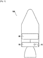
- the figure 1 represents a spacecraft 100 equipped with a rocket engine 50 supplied by a cryogenic propellant tank 60.
- the cryogenic propellant contained in the tank 60 can be used on the one hand to cool the rocket engine 50, but also as fuel for the operation of the rocket motor 50.
- the propellant used for cooling can be completely or partly recycled and for example reinjected into the tank 60, or else rejected.
- fluid is meant “cooling fluid”.
- the rocket motor 50 comprises a cooling circuit, which is not shown, and which is known elsewhere to those skilled in the art.
- the rocket motor 50 comprises, for example within the cooling circuit, a cooling valve 10 for a rocket motor.
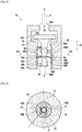
- the figure 2 shows a schematic view of the cooling valve 10.
- the cooling valve 10 comprises a casing 12 provided with a passage 14 extending in an axial direction X.
- the casing 12 also extends in the axial direction X.
- the passage 14 has an inlet of fluid 14A (or inlet 14A) and a fluid outlet 14B (or outlet 14B), fluid being able to flow from inlet 14A to outlet 14B.
- a valve 16 is housed in the housing 12 and is movable relative to the housing 12, within the housing 12, in the axial direction X so as to close / open the passage 12.
- the valve 16 has a closing / opening head 16A. of the passage 14 configured to cooperate with a wall of the passage 14, and a rod 16B extending in the axial direction X.
- the head 16A and the rod 16B are arranged in the passage 12.
- the head 16A has the shape of a Pellet of axis X and extending transversely to the axial direction X.
- the head 16A is configured to cooperate in abutment with a seat 13 defined by the walls of the casing delimiting the passage 14.
- the seat 13 is formed by an annular shoulder separating a wide portion 14C of a narrow portion 14D of the passage 14.
- the wide portion 14C is wide compared to the narrow portion 14D and conversely the narrow portion is narrow compared to the wide portion 14C.
- the inlet 14A opens into the wide portion 14C while the narrow portion 14D opens into the outlet 14B.
- the rod 16B is coupled to the casing 12 by at least one bimetal element 18 configured to deform in the axial direction X as a function of the ambient temperature within the passage 14.
- the rod 16B is coupled to the casing 12 via a single bimetal element 18.
- the rod 16B has two end portions 16B1 and 16B2 opposite in the axial direction X, each end portion 16B1 and 16B2 being slidably received in the axial direction X within a sleeve 20 integral with the housing 12.
- Each sleeve 20 extends in the axial direction X within the passage 14.
- each sleeve 20 is of axis X.
- the valve 10 has more than two sleeves 20. or a single sleeve 20, the sleeve or sleeves possibly being more or less long in the axial direction X.
- Each sleeve 20 is secured to the housing 12 via a radial arm 20A.
- the bimetal element 18 is engaged on the one hand in an annular groove 16B3 of the rod 16B and on the other hand in an annular groove 12A of the housing 12.
- the groove 16B3 is open radially towards the outside of the valve 10 while the groove 12A is open radially towards the inside of the valve 10.
- the bimetal element 18 has a perforated annular shape, ie having openings 17 for the passage of the fluid, the internal annular edge 18A being engaged in the groove 16B3 while the annular edge external 18B is engaged in the groove 12A.
- a bimetal element 18 ' seen in the axial direction X, has a generally rectangular shape, the short sides of the rectangle being engaged in the groove 12A.
- the rectangular shape has a central hole receiving the rod 16B, the edge of this central hole engaging with the groove 16B3.
- Spaces 17 ' are formed between the long sides of the rectangular shape and the walls delimiting the passage 12 for the passage of the fluid.
- the figure 1 shows valve 10 in the open position.
- the fluid circulates according to the arrow F within the valve 10, from the inlet 12A to the outlet 12B, which tends to push the head 16A into the closed position, that is to say towards the seat 13.
- the bimetallic element 18 is deformed in the axial direction X according to the arrow D, which has the effect of approaching or moving the head 16A towards / from the seat 13, thanks to to which passage 12 closes or opens.
- the bimetal element 18 is configured to deform in the axial direction X in order to close the passage 12 when the bimetal element 18 is subjected to a predetermined ambient temperature of between 10 ° K and 150 ° K.
- the bimetallic element 18 consists of two separate materials 19A and 19B, one of the two materials, for example the material 19B, being an alloy based on iron and nickel, for example Fe-Ni36% (known also under the Anglo-Saxon name 64FeNi) or INVAR® while the other material, for example material 19A, is austenitic stainless steel of the 300 series.
- the valve 10 in order to be able to modify the effective closing temperature of the bimetal element 18, the valve 10 is provided with a heating element 22 configured to heat the bimetal element 18.
- the heating element is an electrical resistance 22 bonded to one face of the bimetal element 18.
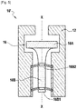
- valve 10 'does not include a sleeve 20 and comprises a plurality of bimetallic elements 18, in this example two bimetallic elements 18.
- Bimetallic elements 18' described above can be used instead of elements 18, or else elements 18 and 18 'can be used in combination.
- the rod 16B is coupled to the housing 12 only by two separate bimetal elements 18 while each end portion 16B1 and 16B2 is connected to a single bimetal element 18.
- Each bimetal element 18 cooperates with the rod 16B and with the housing 12 of similar manner to what has been described above.
- the operation of valve 10 ' is similar to that of valve 10.
Landscapes
- Engineering & Computer Science (AREA)
- Chemical & Material Sciences (AREA)
- Combustion & Propulsion (AREA)
- Mechanical Engineering (AREA)
- General Engineering & Computer Science (AREA)
- Temperature-Responsive Valves (AREA)
- Details Of Valves (AREA)
- Engine Equipment That Uses Special Cycles (AREA)
Abstract
Description
- Le présent exposé concerne une vanne de mise en froid pour moteur-fusée à ergols cryotechniques, un moteur-fusée à ergols cryotechniques comprenant une telle vanne, et un engin spatial équipé d'un tel moteur-fusée.
- La « mise en froid » est une opération au cours de laquelle on amène tout ou partie d'une turbopompe ou d'un autre élément d'un moteur-fusée à une température prédéterminée, en général en la refroidissant, pour que ladite turbopompe soit dans des conditions requises de fonctionnement. En particulier, une turbopompe d'alimentation en ergol pour moteur-fusée est mise en froid avant le démarrage de la turbopompe, c'est-à-dire lorsque la turbopompe est à l'arrêt.
- Le terme « engin spatial » désigne tout engin destiné à être envoyé dans l'espace. Ce terme désigne notamment, mais pas uniquement, un étage de lanceur spatial, un lanceur spatial comprenant un seul étage, une navette spatiale, un satellite ou équivalent.
- Les systèmes connus de mise en froid pour moteur-fusée comprennent généralement des vannes commandées par voie électrique ou pneumatique. Ce type de vanne et le dispositif de commande associé est généralement complexe. Une première simplification de ces dispositifs de commande consiste à commander la fermeture/ouverture de la vanne en fonction de durées prédéterminées, et pas de la température effective au sein du circuit de fluide afin d'éviter des boucles de rétroaction. Toutefois, le refroidissement effectif au sein du circuit fluide n'est pas optimisé. En particulier, la quantité d'ergol consommée lors d'une telle mise en froid est importante pour garantir dans tous les cas le refroidissement à la température requise. Il existe donc un besoin en ce sens.
- Un mode de réalisation concerne une vanne de mise en froid pour moteur-fusée, comprenant un carter pourvu d'un passage s'étendant selon une direction axiale et un clapet logé dans le carter et mobile par rapport au carter selon la direction axiale, le clapet comprenant une tige s'étendant selon la direction axiale et une tête de fermeture/ouverture du passage solidaire de la tige, la tige étant couplée au carter par au moins un élément bilame configuré pour se déformer selon la direction axiale en fonction de la température ambiante au sein du passage
- Par la suite, et sauf indication contraire, par « température ambiante » on entend la température ambiante au sein du passage. Par la suite, et sauf indication contraire, par « la tête » on entend la tête de fermeture/ouverture du passage. Par la suite, et sauf indication contraire, par « l'élément bilame » on entend le au moins un élément bilame.
- La tête du clapet est configurée pour coopérer avec un siège ménagé sur les parois du passage. Lorsque la tête est en appui contre le siège, le passage est fermé (et donc la vanne est fermée), et inversement lorsque la tête est distante du siège, le passage est ouvert (et donc la vanne est ouverte).
- L'élément bilame peut se déformer continument en fonction de la variation de la température ambiante, ou bien de manière discontinue avec un effet de seuil. Un élément bilame permet d'amplifier le mouvement résultant d'une dilatation thermique, ce qui est intéressant pour ouvrir/fermer une vanne en fonction de la température ambiante.
- On comprend que l'élément bilame coopère d'une part avec le carter et d'autre part avec la tige. En se déformant selon la direction axiale, l'élément bilame déplace la tige, et donc l'ensemble du clapet, selon la direction axiale, grâce à quoi la tête s'écarte ou se rapproche du siège de sorte que la vanne s'ouvre ou se ferme.
- La vanne peut être configurée pour être fermée lorsque la température ambiante est inférieure ou égale à une température prédéterminée. En d'autres termes, la vanne peut être configurée pour être ouverte en tout ou partie lorsque la température ambiante est supérieure à la température prédéterminée.
- Lors des opérations de mise en froid, on fait circuler un fluide de refroidissement, par exemple un ergol cryotechnique, dans un circuit fluide s'étendant au sein ou au voisinage de la ou des parties à refroidir (qui est/sont généralement plus chaude(s) que le fluide de refroidissement), le circuit comprenant au moins une vanne selon le présent exposé, par exemple en aval de la ou des parties à refroidir. Le fluide de refroidissement est généralement plus froid que les parties à refroidir. Tant que les parois de la ou des parties à refroidir ne sont pas à la même température que le fluide de refroidissement, les parties réchauffent le fluide de refroidissement, de sorte que la vanne reste ouverte ou partiellement ouverte. Lorsque les parois de la ou des parties à refroidir atteignent une température prédéterminée, par exemple la température initiale du fluide de refroidissement ±10%, alors l'élément bilame se déforme axialement de manière à fermer le passage. Les parois de la ou des parties à refroidir ayant atteint la température souhaitée, il n'est plus nécessaire de faire circuler du fluide de refroidissement. La vanne est donc fermée.
- Dans certains modes de réalisation, la tige est couplée au carter uniquement par deux éléments bilames distincts.
- En d'autres termes la vanne peut comprendre strictement deux éléments bilames. Dans cet exemple, les éléments bilames peuvent servir d'une part à déplacer la tige selon la direction axiale et d'autre part au guidage selon la direction axiale de la tige. Une telle configuration est simple, robuste, garante d'une bonne fiabilité, et économique en terme de coûts récurrents.
- Dans certains modes de réalisation, la tige présente deux portions d'extrémité opposées selon la direction axiale, chaque portion d'extrémité étant reliée à un unique élément bilame.
- Par exemple, une portion d'extrémité peut être une portion qui s'étend jusqu'à 30% de la longueur totale de la tige depuis une extrémité. En reliant chaque portion d'extrémité à un élément bilame on assure un parfait maintien et guidage de la tige selon la direction axiale, ce qui participe à la fiabilité de la vanne et à son bon fonctionnement dans un environnement mécaniquement perturbé, par exemple par des vibrations.
- Dans certains modes de réalisation, la vanne comprend au moins un manchon solidaire du carter, ledit manchon s'étendant selon la direction axiale au sein du passage et recevant la tige en coulissement selon la direction axiale, la tige étant couplée au carter par un unique élément bilame.
- Par la suite, et sauf indication contraire, par « le manchon » on entend le au moins un manchon.
- Dans cet exemple, l'unique élément bilame ne peut servir qu'à déplacer la tige selon la direction axiale tandis que le manchon ne peut servir qu'au guidage selon la direction axiale de la tige. Une telle configuration permet de soulager l'élément bilame et d'assurer un meilleur contrôle de la position selon la direction axiale de la tige.
- Dans certains modes de réalisation, la vanne comprend deux manchons, la tige présentant deux portions d'extrémité opposées selon la direction axiale, chaque portion d'extrémité étant engagée dans un manchon.
- En emmanchant chaque portion d'extrémité dans un manchon, on assure un parfait maintien et guidage de la tige selon la direction axiale, ce qui participe à la fiabilité de la vanne.
- Dans certains modes de réalisation, le au moins un élément bilame présente, vu selon la direction axiale, une forme annulaire ajourée ou une forme générale rectangulaire.
- Par « forme générale » on entend une forme considérée dans son ensemble, sans forcément s'attacher à des variations minimes d'angles ou de bords. De telles forment sont particulièrement efficaces et robustes pour déplacer la tige selon la direction axiale tout en laissant suffisamment d'ouverture pour le passage du fluide de refroidissement entre le carter et la tige.
- Dans certains modes de réalisation, le au moins un élément bilame est configuré pour se déformer selon la direction axiale afin de fermer le passage lorsque l'élément bilame est soumis à une température ambiante prédéterminée comprise entre 10°K (dix degrés Kelvin) et 150°K (cent cinquante degrés Kelvin), par exemple une température de 20°K±10°K (vingt degrés Kelvin plus ou moins dix degrés Kelvin) ou 90°K±10°K (quatre-vingt-dix degrés Kelvin plus ou moins dix degrés Kelvin) ou 110°K±10°K (cent dix degrés Kelvin plus ou moins dix degrés Kelvin).
- De telles valeurs de températures ambiantes sont adaptées pour des mises en froid de moteur-fusée. Par exemple 20°K±10°K peut être bien adaptée pour du dihydrogène (H2) liquide, 90°K±10°K pour du dioxygène (O2) liquide et 110°K±10°K pour du méthane (CH4) liquide.
- Dans certains modes de réalisation, l'élément bilame est constitué de deux matériaux distincts, un des deux matériaux étant un alliage à base de fer et de nickel.
- Par exemple, l'alliage à base de fer et de nickel peut être du Fe-Ni36% (connu également sous la dénomination anglo-saxonne 64FeNi) ou de l'INVAR®. De tels matériaux présentent une très faible sensibilité à la température, grâce à quoi on peut mieux maitriser le comportement du couple des deux matériaux distincts, et donc de l'élément bilame, en fonction de la température. En effet, on peut alors considérer que la déformation de l'élément bilame n'est fonction que d'un seul de deux matériaux, à savoir le matériau qui n'est pas en alliage à base de fer et de nickel.
- Dans certains modes de réalisation, la vanne comprend un élément chauffant configuré pour réchauffer le au moins un élément bilame.
- Par exemple, l'élément chauffant comprend une résistance électrique. Par exemple l'élément chauffant est commandé en tout ou rien.
- Un tel élément chauffant peut permettre de chauffer l'élément bilame, et de fermer la vanne à une température ambiante plus froide que la température prédéterminée, i.e. laisser la vanne ouverte ou rouvrir la vanne au-delà de la température prédéterminée.
- Un mode de réalisation concerne également un moteur-fusée comprenant une vanne de mise en froid selon l'un quelconque des modes de réalisation décrits dans le présent exposé.
- Un mode de réalisation concerne également engin spatial comprenant un moteur-fusée selon l'un quelconque des modes de réalisation décrits dans le présent exposé.
- L'objet du présent exposé et ses avantages seront mieux compris à la lecture de la description détaillée faite ci-après de différents modes de réalisation donnés à titre d'exemples non limitatifs. Cette description fait référence aux pages de figures annexées, sur lesquelles :
- [
Fig. 1 ] Lafigure 1 représente un engin spatial équipé d'un moteur-fusée, - [
Fig. 2 ] Lafigure 2 représente la vanne du circuit de mise en froid du moteur-fusée de lafigure 1 , - [
Fig. 3 ] Lafigure 3 représente l'élément bilame de la vanne de lafigure 2 , vu selon la direction axiale, - [
Fig. 4 ] Lafigure 4 représente une variante de l'élément bilame de lafigure 3 , et - [
Fig. 5 ] Lafigure 5 représente une variante de la vanne de lafigure 2 . - La
figure 1 représente un engin spatial 100 équipé d'un moteur-fusée 50 alimenté par un réservoir d'ergol cryotechnique 60. L'ergol cryotechnique contenu dans le réservoir 60 peut servir d'une part à la mise en froid du moteur-fusée 50, mais également comme carburant pour le fonctionnement du moteur-fusée 50. L'ergol utilisé pour la mise en froid peut être en tout ou partie recyclé et par exemple réinjecté dans le réservoir 60, ou bien rejeté. Par la suite, et sauf indication contraire, par « fluide » on entend « fluide de refroidissement ». - Le moteur-fusée 50 comprend un circuit de mise en froid, qui n'est pas représenté, et qui est connu par ailleurs par l'homme du métier. Le moteur-fusée 50 comprend, par exemple au sein du circuit de mise en froid, une vanne de mise en froid 10 pour moteur-fusée. La
figure 2 représente une vue schématique de la vanne de mise en froid 10. - La vanne de mise en froid 10 comprend un carter 12 pourvu d'un passage 14 s'étendant selon une direction axiale X. Dans cet exemple, le carter 12 s'étend également selon la direction axiale X. Le passage 14 présente une entrée de fluide 14A (ou entrée 14A) et d'une sortie de fluide 14B (ou sortie 14B), du fluide pouvant circuler depuis l'entrée 14A vers la sortie 14B. Un clapet 16 est logé dans le carter 12 et est mobile par rapport au carter 12, au sein du carter 12, selon la direction axiale X de manière à fermer/ouvrir le passage 12. Le clapet 16 présente une tête 16A de fermeture/ouverture du passage 14 configurée pour coopérer avec une paroi du passage 14, et une tige 16B s'étendant selon la direction axiale X. La tête 16A et la tige 16B sont disposées dans le passage 12. Dans cet exemple la tête 16A présente une forme de pastille d'axe X et s'étendant transversalement à la direction axiale X. La tête 16A est configurée pour coopérer en appui avec un siège 13 défini par les parois du carter délimitant le passage 14. Le siège 13 est formé par un épaulement annulaire séparant une portion large 14C d'une portion étroite 14D du passage 14. La portion large 14C est large comparée à la portion étroite 14D et inversement la portion étroite est étroite comparativement à la portion large 14C. Dans cet exemple, l'entrée 14A débouche dans la portion large 14C tandis que la portion étroite 14D débouche sur la sortie 14B.
- La tige 16B est couplée au carter 12 par au moins un élément bilame 18 configuré pour se déformer selon la direction axiale X en fonction de la température ambiante au sein du passage 14. Dans cet exemple, la tige 16B est couplée au carter 12 via un unique élément bilame 18. Dans cet exemple, la tige 16B présente deux portions extrémité 16B1 et 16B2 opposées selon la direction axiale X, chaque portion d'extrémité 16B1 et 16B2 étant reçue en coulissement selon la direction axiale X au sein d'un manchon 20 solidaire du carter 12. Chaque manchon 20 s'étend selon la direction axiale X au sein du passage 14. En d'autres termes, chaque manchon 20 est d'axe X. Selon une variante, la vanne 10 présente plus de deux manchons 20 ou un seul manchon 20, le ou les manchons pouvant être plus ou moins longs selon la direction axiale X. Chaque manchon 20 est solidaire du carter 12 via un bras radial 20A.
- L'élément bilame 18 est engagé d'une part dans une rainure annulaire 16B3 de la tige 16B et d'autre part dans une rainure annulaire 12A du carter 12. Dans cet exemple, la rainure 16B3 est ouverte radialement vers l'extérieur de la vanne 10 tandis que la rainure 12A est ouverte radialement vers l'intérieur de la vanne 10.
- Comme cela est visible sur la
figure 3 , dans cet exemple, vu selon la direction axiale X, l'élément bilame 18 présente une forme annulaire ajourée, i.e. présentant des jours 17 pour le passage du fluide, le bord annulaire interne 18A étant engagé dans la rainure 16B3 tandis que le bord annulaire externe 18B est engagé dans la rainure 12A. Selon une variante représentée sur lafigure 4 , vu selon la direction axiale X, un élément bilame 18' présente une forme générale rectangulaire, les petits côtés du rectangle étant engagés dans la rainure 12A. La forme rectangulaire présente un trou central recevant la tige 16B, le bord de ce trou central s'engageant avec la rainure 16B3. Des espaces 17' sont ménagés entre les grands côtés de la forme rectangulaire et les parois délimitant le passage 12 pour le passage du fluide. - La
figure 1 représente la vanne 10 en position ouverte. En fonctionnement, le fluide circule selon la flèche F au sein de la vanne 10, depuis l'entrée 12A vers la sortie 12B, ce qui a tendance à pousser la tête 16A en position fermée, c'est-à-dire vers le siège 13. En fonction de la température du fluide, l'élément bilame 18 se déforme selon la direction axiale X selon la flèche D, ce qui a pour effet d'approcher ou d'éloigner la tête 16A vers/depuis le siège 13, grâce à quoi le passage 12 se ferme ou s'ouvre. Dans cet exemple, l'élément bilame 18 est configuré pour se déformer selon la direction axiale X afin de fermer le passage 12 lorsque l'élément bilame 18 est soumis à une température ambiante prédéterminée comprise entre 10°K et 150°K. Dans cet exemple, l'élément bilame 18 est constitué de deux matériaux distincts 19A et 19B, un des deux matériaux, par exemple le matériau 19B, étant un alliage à base de fer et de nickel, par exemple du Fe-Ni36% (connu également sous la dénomination anglo-saxonne 64FeNi) ou de l'INVAR® tandis que l'autre matériau, par exemple le matériau 19A, est un acier inoxydable austénitique de la série 300. Dans cet exemple, comme cela est visible sur lafigure 3 , afin de pouvoir modifier la température effective de fermeture de l'élément bilame 18, la vanne 10 est pourvue d'un élément chauffant 22 configuré pour réchauffer l'élément bilame 18. Dans cet exemple, l'élément chauffant est une résistance électrique 22 collée sur une face de l'élément bilame 18. - Selon une variante représentée sur la
figure 5 , la vanne 10' ne comprend pas de manchon 20 et comprend une pluralité d'éléments bilames 18, dans cet exemple deux éléments bilames 18. Des éléments bilames 18' décrits ci-avant peuvent être utilisés à la place des éléments 18, ou bien les éléments 18 et 18' peuvent être utilisés en combinaison. - Dans l'exemple de la
figure 5 , la tige 16B est couplée au carter 12 uniquement par deux éléments bilames 18 distincts tandis que chaque portion d'extrémité 16B1 et 16B2 est reliée à un unique élément bilame 18. Chaque élément bilame 18 coopère avec la tige 16B et avec le carter 12 de manière similaire à ce qui a été décrit ci-avant. Le fonctionnement de la vanne 10' est similaire à celui de la vanne 10. - Bien que la présente invention ait été décrite en se référant à des modes de réalisation spécifiques, il est évident que des modifications et des changements peuvent être effectués sur ces exemples sans sortir de la portée générale de l'invention telle que définie par les revendications. En particulier, des caractéristiques individuelles des différents modes de réalisation illustrés/mentionnés peuvent être combinées dans des modes de réalisation additionnels. Par conséquent, la description et les dessins doivent être considérés dans un sens illustratif plutôt que restrictif.
- Il est également évident que toutes les caractéristiques décrites en référence à un procédé sont transposables, seules ou en combinaison, à un dispositif, et inversement, toutes les caractéristiques décrites en référence à un dispositif sont transposables, seules ou en combinaison, à un procédé.
Claims (10)
- Vanne de mise en froid pour moteur-fusée (10), comprenant un carter (12) pourvu d'un passage (14) s'étendant selon une direction axiale (X) et un clapet (16) logé dans le carter (12) et mobile par rapport au carter (12) selon la direction axiale (X), le clapet (16) comprenant une tige (16B) s'étendant selon la direction axiale (X) et une tête de fermeture/ouverture du passage (16B) solidaire de la tige (16B), la tige (16B) étant couplée au carter (12) par au moins un élément bilame (18, 18') configuré pour se déformer selon la direction axiale (X) en fonction de la température ambiante au sein du passage (14).
- Vanne de mise en froid (10') selon la revendication 1, dans laquelle la tige (16B) est couplée au carter (12) uniquement par deux éléments bilames (18, 18') distincts.
- Vanne de mise en froid (10') selon la revendication 2, dans laquelle la tige (16B) présente deux portions d'extrémité (16B1, 16B2) opposées selon la direction axiale (X), chaque portion d'extrémité (16B1, 16B2) étant reliée à un unique élément bilame (18, 18').
- Vanne de mise en froid (10) selon la revendication 1, comprenant au moins un manchon (20) solidaire du carter (12), ledit manchon (20) s'étendant selon la direction axiale (X) au sein du passage (14) et recevant la tige (16B) en coulissement selon la direction axiale (X), la tige (16B) étant couplée au carter (12) par un unique élément bilame (18, 18').
- Vanne de mise en froid (10) selon la revendication 4, comprenant deux manchons (20), la tige (16B) présentant deux portions d'extrémité (16B1, 16B2) opposées selon la direction axiale (X), chaque portion d'extrémité (16B1, 16B2) étant engagée dans un manchon (20).
- Vanne de mise en froid (10, 10') selon l'une quelconque des revendications 1 à 5, dans laquelle le au moins un élément bilame (18, 18') présente, vu selon la direction axiale (X), une forme annulaire ajourée ou une forme générale rectangulaire.
- Vanne de mise en froid (10, 10') selon l'une quelconque des revendications 1 à 6, dans laquelle le au moins un élément bilame (18, 18') est configuré pour se déformer selon la direction axiale (X) afin de fermer le passage (14) lorsque l'élément bilame (18, 18') est soumis à une température ambiante comprise entre 10°K et 150°K, par exemple une température de 20°K±10°K ou 90°K±10°K ou 110°K±10°K.
- Vanne de mise en froid (10, 10') selon l'une quelconque des revendications 1 à 7, dans laquelle l'élément bilame (18, 18') est constitué de deux matériaux distincts, un des deux matériaux étant un alliage à base de fer et de nickel.
- Vanne de mise en froid (10, 10') selon l'une quelconque des revendications 1 à 8, comprenant un élément chauffant (22) configuré pour réchauffer le au moins un élément bilame (18, 18').
- Moteur-fusée (50) comprenant une vanne de mise en froid (10, 10') selon l'une quelconque des revendications 1 à 9.
Applications Claiming Priority (1)
| Application Number | Priority Date | Filing Date | Title |
|---|---|---|---|
| FR2005278A FR3110640B1 (fr) | 2020-05-20 | 2020-05-20 | Vanne de mise en froid pour moteur-fusée à ergols cryotechniques et moteur fusée comprenant une telle vanne de mise en froid. |
Publications (2)
| Publication Number | Publication Date |
|---|---|
| EP3913209A1 true EP3913209A1 (fr) | 2021-11-24 |
| EP3913209B1 EP3913209B1 (fr) | 2023-03-15 |
Family
ID=72088312
Family Applications (1)
| Application Number | Title | Priority Date | Filing Date |
|---|---|---|---|
| EP21175010.4A Active EP3913209B1 (fr) | 2020-05-20 | 2021-05-20 | VANNE DE MISE EN FROID POUR MOTEUR-FUSÉE À ERGOLS CRYOTECHNIQUES ET 
MOTEUR- FUSÉE COMPRENANT UNE TELLE VANNE DE MISE EN FROID |
Country Status (4)
| Country | Link |
|---|---|
| EP (1) | EP3913209B1 (fr) |
| JP (1) | JP7814110B2 (fr) |
| ES (1) | ES2946167T3 (fr) |
| FR (1) | FR3110640B1 (fr) |
Citations (3)
| Publication number | Priority date | Publication date | Assignee | Title |
|---|---|---|---|---|
| US3132475A (en) * | 1961-06-29 | 1964-05-12 | United Aircraft Corp | Hybrid rocket propulsion system |
| EP2888467A1 (fr) * | 2012-08-22 | 2015-07-01 | SNECMA Services | Procede de mise en froid d'une pompe dans un circuit d'alimentation d'un moteur-fusée |
| FR3049655A1 (fr) * | 2016-04-01 | 2017-10-06 | Snecma | Carter ameliore de turbopompe d'alimentation en ergol pour moteur-fusee |
Family Cites Families (5)
| Publication number | Priority date | Publication date | Assignee | Title |
|---|---|---|---|---|
| JPS6220702Y2 (fr) * | 1980-10-27 | 1987-05-26 | ||
| JPS6330863Y2 (fr) * | 1981-02-18 | 1988-08-17 | ||
| JPH07167378A (ja) * | 1993-12-15 | 1995-07-04 | Kubota Corp | 断熱容器 |
| SI9400154A (en) * | 1994-03-29 | 1995-12-31 | Igor Urban | Reaction rocket engine with synthetic fuel |
| SE538969C2 (sv) * | 2013-10-29 | 2017-03-07 | Scania Cv Ab | Ventilarrangemang för att reglera avgasflödet genom en oxidationskatalysator |
-
2020
- 2020-05-20 FR FR2005278A patent/FR3110640B1/fr active Active
-
2021
- 2021-05-20 JP JP2021085451A patent/JP7814110B2/ja active Active
- 2021-05-20 EP EP21175010.4A patent/EP3913209B1/fr active Active
- 2021-05-20 ES ES21175010T patent/ES2946167T3/es active Active
Patent Citations (3)
| Publication number | Priority date | Publication date | Assignee | Title |
|---|---|---|---|---|
| US3132475A (en) * | 1961-06-29 | 1964-05-12 | United Aircraft Corp | Hybrid rocket propulsion system |
| EP2888467A1 (fr) * | 2012-08-22 | 2015-07-01 | SNECMA Services | Procede de mise en froid d'une pompe dans un circuit d'alimentation d'un moteur-fusée |
| FR3049655A1 (fr) * | 2016-04-01 | 2017-10-06 | Snecma | Carter ameliore de turbopompe d'alimentation en ergol pour moteur-fusee |
Also Published As
| Publication number | Publication date |
|---|---|
| FR3110640A1 (fr) | 2021-11-26 |
| FR3110640B1 (fr) | 2022-06-03 |
| EP3913209B1 (fr) | 2023-03-15 |
| ES2946167T3 (es) | 2023-07-13 |
| JP2021183870A (ja) | 2021-12-02 |
| JP7814110B2 (ja) | 2026-02-16 |
Similar Documents
| Publication | Publication Date | Title |
|---|---|---|
| FR2916479A1 (fr) | Module pour un circuit de refroidissement d'un moteur de vehicule automobile. | |
| FR2957382A1 (fr) | Dispositif pour l'utilisation de la chaleur de gaz d'echappement | |
| WO2015091342A1 (fr) | Vanne de commande pour un circuit de circulation de fluide, notamment pour vehicule automobile | |
| FR2805591A1 (fr) | Dispositif thermostatique a deux regimes de regulation commandes selectivement | |
| EP3913209B1 (fr) | VANNE DE MISE EN FROID POUR MOTEUR-FUSÉE À ERGOLS CRYOTECHNIQUES ET 
MOTEUR- FUSÉE COMPRENANT UNE TELLE VANNE DE MISE EN FROID | |
| EP1674689B1 (fr) | Vanne thermostatique de régulation d'un fluide et circuit de refroidissement incorporant une telle vanne | |
| EP2006585B1 (fr) | Vanne de régulation | |
| EP0388277B1 (fr) | Refroidisseur Joule-Thomson | |
| WO2018229404A1 (fr) | Vanne de derivation pour machine de detente | |
| EP2676057B1 (fr) | Vanne a trois voies. | |
| EP3724740B1 (fr) | Vanne thermostatique | |
| EP1041256A1 (fr) | Dispositif thermostatique à deux régimes de régulation, à deux éléments thermostatiques | |
| EP3216993B1 (fr) | Gicleur de refroidissement de piston | |
| EP1607818B1 (fr) | Vanne thermostatistique pour un circuit de refroidissement | |
| FR3107329A1 (fr) | Vanne multivoies à obturateur rotatif et à commande par pression hydraulique | |
| EP1697668B1 (fr) | Vanne de regulation thermique pour un circuit de circulation de fluide, en particulier pour un circuit de refroidissement d'un moteur | |
| EP4049107B1 (fr) | Vanne thermostatique | |
| FR2699640A1 (fr) | Corps de clapet pour valve de retenue à grand débit. | |
| FR2864151A1 (fr) | Boitier de sortie d'eau | |
| EP3477415B1 (fr) | Vanne thermostatique | |
| FR3051873A1 (fr) | Groupe motopropulseur d’un vehicule | |
| EP1705412B1 (fr) | Actionneur linaire sécurisé | |
| FR2630161A1 (fr) | Thermostat de securite pour un circuit de liquide de refroidissement, notamment dans un moteur | |
| FR2853709A1 (fr) | Vanne thermostatique pour un circuit de refroidissement | |
| EP3557177A1 (fr) | Radiateur de refroidissement avec by-pass intégré et circuit de refroidissement |
Legal Events
| Date | Code | Title | Description |
|---|---|---|---|
| PUAI | Public reference made under article 153(3) epc to a published international application that has entered the european phase |
Free format text: ORIGINAL CODE: 0009012 |
|
| STAA | Information on the status of an ep patent application or granted ep patent |
Free format text: STATUS: REQUEST FOR EXAMINATION WAS MADE |
|
| 17P | Request for examination filed |
Effective date: 20210520 |
|
| AK | Designated contracting states |
Kind code of ref document: A1 Designated state(s): AL AT BE BG CH CY CZ DE DK EE ES FI FR GB GR HR HU IE IS IT LI LT LU LV MC MK MT NL NO PL PT RO RS SE SI SK SM TR |
|
| B565 | Issuance of search results under rule 164(2) epc |
Effective date: 20211001 |
|
| RAP3 | Party data changed (applicant data changed or rights of an application transferred) |
Owner name: ARIANEGROUP SAS |
|
| GRAP | Despatch of communication of intention to grant a patent |
Free format text: ORIGINAL CODE: EPIDOSNIGR1 |
|
| STAA | Information on the status of an ep patent application or granted ep patent |
Free format text: STATUS: GRANT OF PATENT IS INTENDED |
|
| INTG | Intention to grant announced |
Effective date: 20221004 |
|
| GRAS | Grant fee paid |
Free format text: ORIGINAL CODE: EPIDOSNIGR3 |
|
| GRAA | (expected) grant |
Free format text: ORIGINAL CODE: 0009210 |
|
| STAA | Information on the status of an ep patent application or granted ep patent |
Free format text: STATUS: THE PATENT HAS BEEN GRANTED |
|
| AK | Designated contracting states |
Kind code of ref document: B1 Designated state(s): AL AT BE BG CH CY CZ DE DK EE ES FI FR GB GR HR HU IE IS IT LI LT LU LV MC MK MT NL NO PL PT RO RS SE SI SK SM TR |
|
| REG | Reference to a national code |
Ref country code: CH Ref legal event code: EP Ref country code: GB Ref legal event code: FG4D Free format text: NOT ENGLISH |
|
| REG | Reference to a national code |
Ref country code: DE Ref legal event code: R096 Ref document number: 602021001616 Country of ref document: DE |
|
| REG | Reference to a national code |
Ref country code: IE Ref legal event code: FG4D Free format text: LANGUAGE OF EP DOCUMENT: FRENCH |
|
| REG | Reference to a national code |
Ref country code: AT Ref legal event code: REF Ref document number: 1554131 Country of ref document: AT Kind code of ref document: T Effective date: 20230415 |
|
| REG | Reference to a national code |
Ref country code: NL Ref legal event code: FP |
|
| REG | Reference to a national code |
Ref country code: LT Ref legal event code: MG9D |
|
| REG | Reference to a national code |
Ref country code: ES Ref legal event code: FG2A Ref document number: 2946167 Country of ref document: ES Kind code of ref document: T3 Effective date: 20230713 |
|
| P01 | Opt-out of the competence of the unified patent court (upc) registered |
Effective date: 20230612 |
|
| PG25 | Lapsed in a contracting state [announced via postgrant information from national office to epo] |
Ref country code: RS Free format text: LAPSE BECAUSE OF FAILURE TO SUBMIT A TRANSLATION OF THE DESCRIPTION OR TO PAY THE FEE WITHIN THE PRESCRIBED TIME-LIMIT Effective date: 20230315 Ref country code: NO Free format text: LAPSE BECAUSE OF FAILURE TO SUBMIT A TRANSLATION OF THE DESCRIPTION OR TO PAY THE FEE WITHIN THE PRESCRIBED TIME-LIMIT Effective date: 20230615 Ref country code: LV Free format text: LAPSE BECAUSE OF FAILURE TO SUBMIT A TRANSLATION OF THE DESCRIPTION OR TO PAY THE FEE WITHIN THE PRESCRIBED TIME-LIMIT Effective date: 20230315 Ref country code: LT Free format text: LAPSE BECAUSE OF FAILURE TO SUBMIT A TRANSLATION OF THE DESCRIPTION OR TO PAY THE FEE WITHIN THE PRESCRIBED TIME-LIMIT Effective date: 20230315 Ref country code: HR Free format text: LAPSE BECAUSE OF FAILURE TO SUBMIT A TRANSLATION OF THE DESCRIPTION OR TO PAY THE FEE WITHIN THE PRESCRIBED TIME-LIMIT Effective date: 20230315 |
|
| REG | Reference to a national code |
Ref country code: AT Ref legal event code: MK05 Ref document number: 1554131 Country of ref document: AT Kind code of ref document: T Effective date: 20230315 |
|
| PG25 | Lapsed in a contracting state [announced via postgrant information from national office to epo] |
Ref country code: SE Free format text: LAPSE BECAUSE OF FAILURE TO SUBMIT A TRANSLATION OF THE DESCRIPTION OR TO PAY THE FEE WITHIN THE PRESCRIBED TIME-LIMIT Effective date: 20230315 Ref country code: GR Free format text: LAPSE BECAUSE OF FAILURE TO SUBMIT A TRANSLATION OF THE DESCRIPTION OR TO PAY THE FEE WITHIN THE PRESCRIBED TIME-LIMIT Effective date: 20230616 Ref country code: FI Free format text: LAPSE BECAUSE OF FAILURE TO SUBMIT A TRANSLATION OF THE DESCRIPTION OR TO PAY THE FEE WITHIN THE PRESCRIBED TIME-LIMIT Effective date: 20230315 |
|
| REG | Reference to a national code |
Ref country code: CH Ref legal event code: PK Free format text: TITRE |
|
| PG25 | Lapsed in a contracting state [announced via postgrant information from national office to epo] |
Ref country code: SM Free format text: LAPSE BECAUSE OF FAILURE TO SUBMIT A TRANSLATION OF THE DESCRIPTION OR TO PAY THE FEE WITHIN THE PRESCRIBED TIME-LIMIT Effective date: 20230315 Ref country code: RO Free format text: LAPSE BECAUSE OF FAILURE TO SUBMIT A TRANSLATION OF THE DESCRIPTION OR TO PAY THE FEE WITHIN THE PRESCRIBED TIME-LIMIT Effective date: 20230315 Ref country code: PT Free format text: LAPSE BECAUSE OF FAILURE TO SUBMIT A TRANSLATION OF THE DESCRIPTION OR TO PAY THE FEE WITHIN THE PRESCRIBED TIME-LIMIT Effective date: 20230717 Ref country code: EE Free format text: LAPSE BECAUSE OF FAILURE TO SUBMIT A TRANSLATION OF THE DESCRIPTION OR TO PAY THE FEE WITHIN THE PRESCRIBED TIME-LIMIT Effective date: 20230315 Ref country code: CZ Free format text: LAPSE BECAUSE OF FAILURE TO SUBMIT A TRANSLATION OF THE DESCRIPTION OR TO PAY THE FEE WITHIN THE PRESCRIBED TIME-LIMIT Effective date: 20230315 Ref country code: AT Free format text: LAPSE BECAUSE OF FAILURE TO SUBMIT A TRANSLATION OF THE DESCRIPTION OR TO PAY THE FEE WITHIN THE PRESCRIBED TIME-LIMIT Effective date: 20230315 |
|
| PG25 | Lapsed in a contracting state [announced via postgrant information from national office to epo] |
Ref country code: SK Free format text: LAPSE BECAUSE OF FAILURE TO SUBMIT A TRANSLATION OF THE DESCRIPTION OR TO PAY THE FEE WITHIN THE PRESCRIBED TIME-LIMIT Effective date: 20230315 Ref country code: PL Free format text: LAPSE BECAUSE OF FAILURE TO SUBMIT A TRANSLATION OF THE DESCRIPTION OR TO PAY THE FEE WITHIN THE PRESCRIBED TIME-LIMIT Effective date: 20230315 Ref country code: IS Free format text: LAPSE BECAUSE OF FAILURE TO SUBMIT A TRANSLATION OF THE DESCRIPTION OR TO PAY THE FEE WITHIN THE PRESCRIBED TIME-LIMIT Effective date: 20230715 |
|
| REG | Reference to a national code |
Ref country code: DE Ref legal event code: R097 Ref document number: 602021001616 Country of ref document: DE |
|
| PG25 | Lapsed in a contracting state [announced via postgrant information from national office to epo] |
Ref country code: MC Free format text: LAPSE BECAUSE OF FAILURE TO SUBMIT A TRANSLATION OF THE DESCRIPTION OR TO PAY THE FEE WITHIN THE PRESCRIBED TIME-LIMIT Effective date: 20230315 |
|
| PLBE | No opposition filed within time limit |
Free format text: ORIGINAL CODE: 0009261 |
|
| STAA | Information on the status of an ep patent application or granted ep patent |
Free format text: STATUS: NO OPPOSITION FILED WITHIN TIME LIMIT |
|
| PG25 | Lapsed in a contracting state [announced via postgrant information from national office to epo] |
Ref country code: SI Free format text: LAPSE BECAUSE OF FAILURE TO SUBMIT A TRANSLATION OF THE DESCRIPTION OR TO PAY THE FEE WITHIN THE PRESCRIBED TIME-LIMIT Effective date: 20230315 Ref country code: MC Free format text: LAPSE BECAUSE OF FAILURE TO SUBMIT A TRANSLATION OF THE DESCRIPTION OR TO PAY THE FEE WITHIN THE PRESCRIBED TIME-LIMIT Effective date: 20230315 Ref country code: LU Free format text: LAPSE BECAUSE OF NON-PAYMENT OF DUE FEES Effective date: 20230520 Ref country code: DK Free format text: LAPSE BECAUSE OF FAILURE TO SUBMIT A TRANSLATION OF THE DESCRIPTION OR TO PAY THE FEE WITHIN THE PRESCRIBED TIME-LIMIT Effective date: 20230315 |
|
| 26N | No opposition filed |
Effective date: 20231218 |
|
| REG | Reference to a national code |
Ref country code: IE Ref legal event code: MM4A |
|
| PG25 | Lapsed in a contracting state [announced via postgrant information from national office to epo] |
Ref country code: IE Free format text: LAPSE BECAUSE OF NON-PAYMENT OF DUE FEES Effective date: 20230520 |
|
| PG25 | Lapsed in a contracting state [announced via postgrant information from national office to epo] |
Ref country code: IE Free format text: LAPSE BECAUSE OF NON-PAYMENT OF DUE FEES Effective date: 20230520 |
|
| PG25 | Lapsed in a contracting state [announced via postgrant information from national office to epo] |
Ref country code: BG Free format text: LAPSE BECAUSE OF FAILURE TO SUBMIT A TRANSLATION OF THE DESCRIPTION OR TO PAY THE FEE WITHIN THE PRESCRIBED TIME-LIMIT Effective date: 20230315 |
|
| PG25 | Lapsed in a contracting state [announced via postgrant information from national office to epo] |
Ref country code: BG Free format text: LAPSE BECAUSE OF FAILURE TO SUBMIT A TRANSLATION OF THE DESCRIPTION OR TO PAY THE FEE WITHIN THE PRESCRIBED TIME-LIMIT Effective date: 20230315 |
|
| REG | Reference to a national code |
Ref country code: CH Ref legal event code: PL |
|
| PG25 | Lapsed in a contracting state [announced via postgrant information from national office to epo] |
Ref country code: CH Free format text: LAPSE BECAUSE OF NON-PAYMENT OF DUE FEES Effective date: 20240531 |
|
| PGFP | Annual fee paid to national office [announced via postgrant information from national office to epo] |
Ref country code: NL Payment date: 20250521 Year of fee payment: 5 |
|
| PGFP | Annual fee paid to national office [announced via postgrant information from national office to epo] |
Ref country code: DE Payment date: 20250521 Year of fee payment: 5 |
|
| PGFP | Annual fee paid to national office [announced via postgrant information from national office to epo] |
Ref country code: BE Payment date: 20250521 Year of fee payment: 5 Ref country code: IT Payment date: 20250527 Year of fee payment: 5 |
|
| PGFP | Annual fee paid to national office [announced via postgrant information from national office to epo] |
Ref country code: FR Payment date: 20250528 Year of fee payment: 5 |
|
| PG25 | Lapsed in a contracting state [announced via postgrant information from national office to epo] |
Ref country code: CY Free format text: LAPSE BECAUSE OF FAILURE TO SUBMIT A TRANSLATION OF THE DESCRIPTION OR TO PAY THE FEE WITHIN THE PRESCRIBED TIME-LIMIT; INVALID AB INITIO Effective date: 20210520 |
|
| PG25 | Lapsed in a contracting state [announced via postgrant information from national office to epo] |
Ref country code: HU Free format text: LAPSE BECAUSE OF FAILURE TO SUBMIT A TRANSLATION OF THE DESCRIPTION OR TO PAY THE FEE WITHIN THE PRESCRIBED TIME-LIMIT; INVALID AB INITIO Effective date: 20210520 |
|
| PGFP | Annual fee paid to national office [announced via postgrant information from national office to epo] |
Ref country code: ES Payment date: 20250630 Year of fee payment: 5 |
|
| PG25 | Lapsed in a contracting state [announced via postgrant information from national office to epo] |
Ref country code: TR Free format text: LAPSE BECAUSE OF FAILURE TO SUBMIT A TRANSLATION OF THE DESCRIPTION OR TO PAY THE FEE WITHIN THE PRESCRIBED TIME-LIMIT Effective date: 20230315 |
|
| PGFP | Annual fee paid to national office [announced via postgrant information from national office to epo] |
Ref country code: GB Payment date: 20260306 Year of fee payment: 6 |