EP3913194A1 - Variable vane assembly and method for operating a variable vane assembly - Google Patents
Variable vane assembly and method for operating a variable vane assembly Download PDFInfo
- Publication number
- EP3913194A1 EP3913194A1 EP21175122.7A EP21175122A EP3913194A1 EP 3913194 A1 EP3913194 A1 EP 3913194A1 EP 21175122 A EP21175122 A EP 21175122A EP 3913194 A1 EP3913194 A1 EP 3913194A1
- Authority
- EP
- European Patent Office
- Prior art keywords
- trunnion
- bushing
- assembly
- surface modification
- content
- Prior art date
- Legal status (The legal status is an assumption and is not a legal conclusion. Google has not performed a legal analysis and makes no representation as to the accuracy of the status listed.)
- Granted
Links
Images



Classifications
-
- F—MECHANICAL ENGINEERING; LIGHTING; HEATING; WEAPONS; BLASTING
- F01—MACHINES OR ENGINES IN GENERAL; ENGINE PLANTS IN GENERAL; STEAM ENGINES
- F01D—NON-POSITIVE DISPLACEMENT MACHINES OR ENGINES, e.g. STEAM TURBINES
- F01D17/00—Regulating or controlling by varying flow
- F01D17/10—Final actuators
- F01D17/12—Final actuators arranged in stator parts
- F01D17/14—Final actuators arranged in stator parts varying effective cross-sectional area of nozzles or guide conduits
- F01D17/16—Final actuators arranged in stator parts varying effective cross-sectional area of nozzles or guide conduits by means of nozzle vanes
- F01D17/162—Final actuators arranged in stator parts varying effective cross-sectional area of nozzles or guide conduits by means of nozzle vanes for axial flow, i.e. the vanes turning around axes which are essentially perpendicular to the rotor centre line
-
- F—MECHANICAL ENGINEERING; LIGHTING; HEATING; WEAPONS; BLASTING
- F04—POSITIVE - DISPLACEMENT MACHINES FOR LIQUIDS; PUMPS FOR LIQUIDS OR ELASTIC FLUIDS
- F04D—NON-POSITIVE-DISPLACEMENT PUMPS
- F04D29/00—Details, component parts, or accessories
- F04D29/02—Selection of particular materials
- F04D29/023—Selection of particular materials especially adapted for elastic fluid pumps
-
- F—MECHANICAL ENGINEERING; LIGHTING; HEATING; WEAPONS; BLASTING
- F04—POSITIVE - DISPLACEMENT MACHINES FOR LIQUIDS; PUMPS FOR LIQUIDS OR ELASTIC FLUIDS
- F04D—NON-POSITIVE-DISPLACEMENT PUMPS
- F04D29/00—Details, component parts, or accessories
- F04D29/40—Casings; Connections of working fluid
- F04D29/52—Casings; Connections of working fluid for axial pumps
- F04D29/54—Fluid-guiding means, e.g. diffusers
- F04D29/541—Specially adapted for elastic fluid pumps
- F04D29/542—Bladed diffusers
-
- F—MECHANICAL ENGINEERING; LIGHTING; HEATING; WEAPONS; BLASTING
- F04—POSITIVE - DISPLACEMENT MACHINES FOR LIQUIDS; PUMPS FOR LIQUIDS OR ELASTIC FLUIDS
- F04D—NON-POSITIVE-DISPLACEMENT PUMPS
- F04D29/00—Details, component parts, or accessories
- F04D29/40—Casings; Connections of working fluid
- F04D29/52—Casings; Connections of working fluid for axial pumps
- F04D29/54—Fluid-guiding means, e.g. diffusers
- F04D29/56—Fluid-guiding means, e.g. diffusers adjustable
- F04D29/563—Fluid-guiding means, e.g. diffusers adjustable specially adapted for elastic fluid pumps
-
- F—MECHANICAL ENGINEERING; LIGHTING; HEATING; WEAPONS; BLASTING
- F05—INDEXING SCHEMES RELATING TO ENGINES OR PUMPS IN VARIOUS SUBCLASSES OF CLASSES F01-F04
- F05D—INDEXING SCHEME FOR ASPECTS RELATING TO NON-POSITIVE-DISPLACEMENT MACHINES OR ENGINES, GAS-TURBINES OR JET-PROPULSION PLANTS
- F05D2230/00—Manufacture
- F05D2230/30—Manufacture with deposition of material
- F05D2230/31—Layer deposition
-
- F—MECHANICAL ENGINEERING; LIGHTING; HEATING; WEAPONS; BLASTING
- F05—INDEXING SCHEMES RELATING TO ENGINES OR PUMPS IN VARIOUS SUBCLASSES OF CLASSES F01-F04
- F05D—INDEXING SCHEME FOR ASPECTS RELATING TO NON-POSITIVE-DISPLACEMENT MACHINES OR ENGINES, GAS-TURBINES OR JET-PROPULSION PLANTS
- F05D2230/00—Manufacture
- F05D2230/30—Manufacture with deposition of material
- F05D2230/31—Layer deposition
- F05D2230/313—Layer deposition by physical vapour deposition
-
- F—MECHANICAL ENGINEERING; LIGHTING; HEATING; WEAPONS; BLASTING
- F05—INDEXING SCHEMES RELATING TO ENGINES OR PUMPS IN VARIOUS SUBCLASSES OF CLASSES F01-F04
- F05D—INDEXING SCHEME FOR ASPECTS RELATING TO NON-POSITIVE-DISPLACEMENT MACHINES OR ENGINES, GAS-TURBINES OR JET-PROPULSION PLANTS
- F05D2230/00—Manufacture
- F05D2230/30—Manufacture with deposition of material
- F05D2230/31—Layer deposition
- F05D2230/314—Layer deposition by chemical vapour deposition
-
- F—MECHANICAL ENGINEERING; LIGHTING; HEATING; WEAPONS; BLASTING
- F05—INDEXING SCHEMES RELATING TO ENGINES OR PUMPS IN VARIOUS SUBCLASSES OF CLASSES F01-F04
- F05D—INDEXING SCHEME FOR ASPECTS RELATING TO NON-POSITIVE-DISPLACEMENT MACHINES OR ENGINES, GAS-TURBINES OR JET-PROPULSION PLANTS
- F05D2230/00—Manufacture
- F05D2230/90—Coating; Surface treatment
-
- F—MECHANICAL ENGINEERING; LIGHTING; HEATING; WEAPONS; BLASTING
- F05—INDEXING SCHEMES RELATING TO ENGINES OR PUMPS IN VARIOUS SUBCLASSES OF CLASSES F01-F04
- F05D—INDEXING SCHEME FOR ASPECTS RELATING TO NON-POSITIVE-DISPLACEMENT MACHINES OR ENGINES, GAS-TURBINES OR JET-PROPULSION PLANTS
- F05D2240/00—Components
- F05D2240/10—Stators
- F05D2240/12—Fluid guiding means, e.g. vanes
-
- F—MECHANICAL ENGINEERING; LIGHTING; HEATING; WEAPONS; BLASTING
- F05—INDEXING SCHEMES RELATING TO ENGINES OR PUMPS IN VARIOUS SUBCLASSES OF CLASSES F01-F04
- F05D—INDEXING SCHEME FOR ASPECTS RELATING TO NON-POSITIVE-DISPLACEMENT MACHINES OR ENGINES, GAS-TURBINES OR JET-PROPULSION PLANTS
- F05D2300/00—Materials; Properties thereof
- F05D2300/20—Oxide or non-oxide ceramics
- F05D2300/22—Non-oxide ceramics
- F05D2300/224—Carbon, e.g. graphite
-
- F—MECHANICAL ENGINEERING; LIGHTING; HEATING; WEAPONS; BLASTING
- F05—INDEXING SCHEMES RELATING TO ENGINES OR PUMPS IN VARIOUS SUBCLASSES OF CLASSES F01-F04
- F05D—INDEXING SCHEME FOR ASPECTS RELATING TO NON-POSITIVE-DISPLACEMENT MACHINES OR ENGINES, GAS-TURBINES OR JET-PROPULSION PLANTS
- F05D2300/00—Materials; Properties thereof
- F05D2300/50—Intrinsic material properties or characteristics
- F05D2300/509—Self lubricating materials; Solid lubricants
-
- Y—GENERAL TAGGING OF NEW TECHNOLOGICAL DEVELOPMENTS; GENERAL TAGGING OF CROSS-SECTIONAL TECHNOLOGIES SPANNING OVER SEVERAL SECTIONS OF THE IPC; TECHNICAL SUBJECTS COVERED BY FORMER USPC CROSS-REFERENCE ART COLLECTIONS [XRACs] AND DIGESTS
- Y02—TECHNOLOGIES OR APPLICATIONS FOR MITIGATION OR ADAPTATION AGAINST CLIMATE CHANGE
- Y02T—CLIMATE CHANGE MITIGATION TECHNOLOGIES RELATED TO TRANSPORTATION
- Y02T50/00—Aeronautics or air transport
- Y02T50/60—Efficient propulsion technologies, e.g. for aircraft
Definitions
- the disclosure (invention) relates to variable vanes and vane bushings and, more particularly, to a low friction, wear resistant interface between these components.
- Gas turbine engines such as those that power modern aircraft generally include a compressor section to pressurize an airflow, a combustor section to burn a hydrocarbon fuel in the presence of the pressurized air, and a turbine section to extract energy from the resultant combustion gases.
- variable stator vanes that can be pivoted about their individual axes to change an operational performance characteristic of the engine.
- the variable stator vanes are robustly designed to handle the stress loads that are applied to change the position of the vanes.
- Variable vanes can be operated at relatively high temperatures ranges, approaching temperatures of 700°F, and under increased vibratory motion as compared to legacy variable vanes. Under these conditions, the variable vanes and bushings with which they interact have experienced significant wear. Variable vanes and bushings can typically have an interaction that exhibits low roughness of the surfaces and variability or fluctuations in the contact pressure between the components. These conditions are not well suited to formation of a transfer film between the components, leading to long break-in periods and consequently high friction and wear.
- a variable vane assembly comprises a variable vane; a trunnion arranged on one end of the variable vane; a bushing mated to the trunnion to define an interface between the trunnion and the bushing; and a surface modification on at least one of the trunnion and the bushing at the interface, whereby frictional heating at the interface during operation of the assembly is reduced.
- the surface modification comprises an amorphous hydrogenated carbon coating.
- the amorphous hydrogenated carbon coating comprises less than 30 at% hydrogen.
- the amorphous hydrogenated carbon coating comprises between 3 and 30 at% hydrogen.
- the amorphous hydrogenated coating comprises less than 20 at% hydrogen.
- the amorphous hydrogenated carbon coating has an sp 2 content and an sp 3 content, and wherein the sp 2 content is greater than the sp 3 content.
- the amorphous hydrogenated carbon coating has a ratio of sp 2 :sp 3 of between 1.4 and 1.6.
- the amorphous hydrogenated carbon coating comprises a plurality of layers including an outermost layer with reference to an underlying trunnion or bushing, and at least one bulk layer between the outermost layer and the underlying trunnion or bushing, and wherein the outermost layer has a higher sp2:sp 3 ratio than the at least one bulk layer.
- the assembly further comprises an adhesion layer between an underlying trunnion or bushing and the surface modification, wherein the adhesion layer enhances adhesion of the surface modification to the underlying trunnion or bushing.
- the adhesion layer is a different material from the surface modification.
- the coating further comprises a tungsten or silicon dopant.
- the coating has a thickness of between 100 and 200 nm.
- the surface modification is on the trunnion.
- the trunnion comprises a nickel chromium alloy material, and wherein the bushing comprises a graphite material.
- the bushing comprises a molded carbon composite material.
- a method for operating a variable vane assembly comprises the steps of: applying a film to at least one surface of an interface between a variable vane having a trunnion, and a bushing mated to the trunnion; and operating the assembly such that surfaces at the interface are subjected to fretting and translating contact, whereby a transfer film is generated on surfaces contacting the at least one surface, thereby reducing friction and frictional heating at the interface.
- the applying step comprises applying a surface modification to the at least one surface.
- the surface modification comprises an amorphous hydrogenated carbon coating comprising less than 30 at% hydrogen and has a film thickness of between 100 and 200 nm.
- the amorphous hydrogenated carbon coating has an sp 2 content and an sp 3 content, and wherein the sp 2 content is greater than the sp 3 content.
- the film is applied by physical vapor deposition, chemical vapor deposition, sputtering or combinations thereof.
- the present disclosure relates to variable vanes and bushings and, more particularly, to an interface between these components that produces low friction, wear resistant interaction between them.
- FIG. 1 schematically illustrates a gas turbine engine 20.
- the gas turbine engine 20 is disclosed herein as a two-spool geared turbofan (GTF) that generally incorporates a fan section 22, a compressor section 24, a combustor section 26 and a turbine section 28.
- GTF two-spool geared turbofan
- Alternative engine architectures might include various other sections, systems or features which are not illustrated herein, and the present disclosure is readily pertinent to such alternative engine architectures.
- the fan section 22 drives air along a bypass flowpath while the compressor section 24 drives air along a core flowpath for compression and communication into the combustor section 26, and then expansion through the turbine section 28.
- a GTF in the disclosed non-limiting embodiment, it should be understood that the concepts described herein are not limited to use with a GTF as the teachings may be applied to other types of turbine engines such as a direct drive turbofan with high or low bypass turbofan, turbojets, turboshafts, and three spool (plus fan) turbofans wherein an intermediate spool includes an intermediate pressure compressor (IPC) between a low pressure compressor (LPC) and a high pressure compressor (HPC), and an intermediate pressure turbine (IPT) between the high pressure turbine (HPT) and the low pressure turbine (LPT).
- IPC intermediate pressure compressor
- LPC low pressure compressor
- HPC high pressure compressor
- IPT intermediate pressure turbine
- the engine 20 generally includes a low spool 30 and a high spool 32 mounted for rotation about an engine central longitudinal axis A relative to an engine static structure 36 via several bearing compartments 38.
- the low spool 30 generally includes an inner shaft 40 that interconnects a fan 42, a low pressure compressor 44 (LPC) and a low pressure turbine 46 (LPT).
- the inner shaft 40 drives the fan 42 directly or thru a geared architecture 48 to drive the fan 42 at a lower speed than the low spool 30.
- An exemplary reduction transmission is an epicyclic transmission, namely a planetary or star gear system.
- the high spool 32 includes an outer shaft 50 that interconnects a high pressure compressor 52 (HPC) and high pressure turbine 54 (HPT).
- HPC high pressure compressor
- HPT high pressure turbine
- a combustor 56 is arranged between the HPC 52 and the HPT 54.
- the inner shaft 40 and the outer shaft 50 are concentric and rotate about the engine central longitudinal axis A which is collinear with their longitudinal axes.
- Variable vanes are positioned at locations along the flow path, as schematically illustrated at 58 in FIG. 1 .
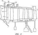
- FIG. 2 shows an enlarged area of FIG. 1 with the position of variable vanes 58 more clearly illustrated.
- FIG. 2 shows a vane 60 mounted at one end to a support 62. Vane 60 is rotatable around an axis X, and rotation is controlled by a vane arm 64 connected to vane 60 at one end and an actuator 66 at the other end.
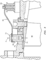
- FIG. 3 further illustrates these components, and shows vane 60 with a trunnion 68 received in or mated with a bushing 70.
- FIG. 3 shows a fastener 72 securing vane arm 64 to trunnion 68 such that movement can be conveyed from actuator 66 through arm 64 to rotate trunnion 68 and vane 60 to a desired position.
- variable vane assembly During operation of a variable vane assembly as disclosed herein, with current and next generation engines, the variable vane assembly can be exposed to temperatures as high as 700 °F (370 °C), and extreme fretting and sliding contact, for example in the interface 74 between trunnion 68 and bushing 70.
- temperatures as high as 700 °F (370 °C)
- extreme fretting and sliding contact for example in the interface 74 between trunnion 68 and bushing 70.
- both the trunnion and the bushing can be exposed to damaging wear due to fretting and sliding at high temperature.
- bushings without a coating as disclosed herein are visibly worn at both upper and lower portions. This wear is believed to be due to failure of a transfer film to form on the bushing because of the low surface roughness of these components, as well as variability and fluctuation in the contact pressure between the components. It is difficult for a transfer film to transfer under such circumstances.
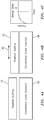
- FIG. 4a schematically illustrates a mated graphite bushing 70 and a counterface or vane trunnion 68 in an unworn state.
- FIG. 4b shows the same surface after operation, and subjecting the bushing to fretting and sliding as shown by arrow 80. Without the formation of a transfer film, which is problematic under the expected operating conditions as stated above, a high coefficient of friction causes increase in heat at the surface which leads to excessive wearing of the respective surfaces.
- FIG. 4c illustrates an increasing friction coefficient at initial operation or break in operation, and reaches steady state at an elevated level.
- a surface treatment or modification to at least one of the surfaces defining interface 74.
- the surface modification alters the characteristics of at least one of the surfaces to encourage formation of a transfer film of carbon, for example on the bushing, leading to reduction in the coefficient of friction as well as heat at the interface.
- FIGS. 5a, 5b and 5c schematically illustrate interface 74 between bushing 70 and trunnion 68, with a surface modification 82 in this case applied initially to trunnion 68.
- FIG. 5a shows such a configuration in an unworn state.
- FIG. 5b illustrates interface 74 and related components in a worn state, after operation at high temperature and fretting or sliding motion (arrow 80).
- the surface modification 82 helps to reduce the coefficient of friction at interface 74, which in turn helps to reduce temperature at the interface, as well as excessive wear of either of the components.
- FIG. 5c illustrates the plot of coefficient of friction over time, and it can be seen that the relationship drops immediately and reaches steady state operation faster, and at a lower friction, than does the assembly without surface modification as illustrated in FIGS. 4a, 4b and 4c .
- One non-limiting embodiment of the surface modification of the present disclosure is a coating of amorphous carbon, especially amorphous hydrogenated carbon, or aC:H.
- This coating can have a hydrogen content of up to about 30 at%, and in one non-limiting configuration can have a hydrogen content of at least 5 at% and up to about 30 at%. In a further non-limiting configuration, the hydrogen content can be up to about 20 at%.
- the amorphous hydrogenated carbon can have an sp 2 content that is greater than the sp 3 content, that is, sp 2 > sp 3 .
- a ratio of sp 2 content:sp 3 content, or sp 2 :sp 3 ratio, can advantageously be between 1.4 and 1.6, and one non-limiting example of a suitable ratio is 1.5.
- amorphous refers to a phase that is substantially without a clearly defined crystalline shape or form. It should be appreciated, however, that in the context of an amorphous hydrogenated carbon film or coating as referred to in the present disclosure, there can be some crystals or nanocrystals distributed through the film or coating, and such material overall is still considered to be within the scope of the term as used herein.
- FIG. 6 illustrates a further non-limiting configuration wherein surface modification 82 has a plurality of layers.
- These layers 82 can include an outermost layer 84 which is considered outermost with reference to the underlying component, be it trunnion 68 or bushing 70.
- Beneath outermost layer 84 are a plurality of additional layers 86 that constitute the bulk of the layers or coating.
- An adhesion layer 88 can also be included to enhance adhesion of surface modification 82 to the underlying trunnion 68 or bushing 70.
- outermost layer 84 can have a higher sp 2 : sp 3 ratio than the layers 86 in the bulk of the coating.
- different layers can be applied one at a time with changes in materials or application procedures to provide the desired different layer properties.
- adhesion layer 88 When an adhesion layer 88 is desired, suitable materials for adhesion layer 88 are different from the other coating layers, and suitable examples of material for an adhesion layer include but are not limited to titanium, aluminum and chromium based adhesive materials or layers.
- Surface modification 82 can be applied to either surface of the interface 74, but generally it will be easier to apply to a non-graphitic surface, and therefore it may be desired to apply to trunnion 68. If applied to bushing 70, care must be taken to ensure material compatibility such that the coating will stay in place. Alternatively, or in addition, an adhesion layer can be utilized as set forth above.
- Surface modification 82 can be applied as a film having a thickness of between 100 and 200 nm.
- the film can be applied using any known technique, for example by PVD, CVD sputtering the like.
- trunnion 68 and bushing 70 can be any suitable material.
- trunnion 68 is made from, or comprises, a nickel chromium alloy material such as IN 718 as one non-limiting example of material.
- Bushing 70 can be made of or comprise a graphitic material, such as molded carbon composite.
- trunnion 68 formed of a nickel chromium alloy and bushing 70 formed of molded carbon or graphite surface modification 82 can be applied to trunnion 68 as this material can be difficult to apply to graphite.
- surface modification 82 it may be desirable to apply surface modification 82 to bushing 70 instead of or in addition to trunnion 68, particularly if materials are being used for the bushing that do not discourage deposition of amorphous carbon film.
- the film serves to reduce initial coefficient of friction during initial operation, and also to initiate a transfer film to bushing 70 during such initial operation or "break in", such that the coefficient of friction starts at a lower value (compare FIG. 4c and FIG. 5c ), and over time the coefficient of friction decreases as shown in FIG. 5c .
- a dopant or other additional material may be added to the amorphous hydrogenated carbon film.
- tungsten bonds with carbon and can improve the hardness and wear resistance of the material.
- silicon is another possible additive. It should be appreciated that other materials could be added to the film or surface modification as would be known to persons having ordinary skill in the art, for example to improve properties of the film or assembly in other respects.
- FIGS. 7 and 8 show results obtained performing a rig test using a coated interface, treated with a thin film of aC:H as disclosed herein and also using a non-coated interface as a baseline.
- the materials used for the bushing and counterface were electrographitic carbon and the coated interface was coated with an a-C:H film having a thickness of 100 nm.
- FIG. 7 shows normalized wear behavior in terms of time spent above an elevated temperature for the baseline system, shown at 90, and the coated system at 92. The coated system shows significantly less time above elevated temperature.
- FIG. 8 shows results in terms of average change in height for the baseline system 90 and the DLC coated system 92. Change in height is reflective of loss of material due to wear, and it is clear that the wear is significantly greater for the baseline system.
- the system with surface modification coating as disclosed herein produces improved behavior in terms of less loss of material or height and also appreciably reduced time above elevated temperature.
- variable vane assembly with a surface modification as disclosed herein helps to produce a carbon transfer film to the non-treated surface and thereby create a solid lubricated system.
Landscapes
- Engineering & Computer Science (AREA)
- Mechanical Engineering (AREA)
- General Engineering & Computer Science (AREA)
- Chemical Vapour Deposition (AREA)
- Physical Vapour Deposition (AREA)
Abstract
Description
- The disclosure (invention) relates to variable vanes and vane bushings and, more particularly, to a low friction, wear resistant interface between these components.
- Gas turbine engines such as those that power modern aircraft generally include a compressor section to pressurize an airflow, a combustor section to burn a hydrocarbon fuel in the presence of the pressurized air, and a turbine section to extract energy from the resultant combustion gases.
- Some gas turbine engines include variable stator vanes that can be pivoted about their individual axes to change an operational performance characteristic of the engine. Typically, the variable stator vanes are robustly designed to handle the stress loads that are applied to change the position of the vanes.
- Variable vanes can be operated at relatively high temperatures ranges, approaching temperatures of 700°F, and under increased vibratory motion as compared to legacy variable vanes. Under these conditions, the variable vanes and bushings with which they interact have experienced significant wear. Variable vanes and bushings can typically have an interaction that exhibits low roughness of the surfaces and variability or fluctuations in the contact pressure between the components. These conditions are not well suited to formation of a transfer film between the components, leading to long break-in periods and consequently high friction and wear.
- In one aspect of the invention, a variable vane assembly comprises a variable vane; a trunnion arranged on one end of the variable vane; a bushing mated to the trunnion to define an interface between the trunnion and the bushing; and a surface modification on at least one of the trunnion and the bushing at the interface, whereby frictional heating at the interface during operation of the assembly is reduced.
- Optionally, the surface modification comprises an amorphous hydrogenated carbon coating.
- Optionally, the amorphous hydrogenated carbon coating comprises less than 30 at% hydrogen.
- Optionally, the amorphous hydrogenated carbon coating comprises between 3 and 30 at% hydrogen.
- Optionally, the amorphous hydrogenated coating comprises less than 20 at% hydrogen.
- Optionally, the amorphous hydrogenated carbon coating has an sp2 content and an sp3 content, and wherein the sp2 content is greater than the sp3 content.
- Optionally, the amorphous hydrogenated carbon coating has a ratio of sp2:sp3 of between 1.4 and 1.6.
- Optionally, the amorphous hydrogenated carbon coating comprises a plurality of layers including an outermost layer with reference to an underlying trunnion or bushing, and at least one bulk layer between the outermost layer and the underlying trunnion or bushing, and wherein the outermost layer has a higher sp2:sp3 ratio than the at least one bulk layer.
- Optionally, the assembly further comprises an adhesion layer between an underlying trunnion or bushing and the surface modification, wherein the adhesion layer enhances adhesion of the surface modification to the underlying trunnion or bushing.
- Optionally, the adhesion layer is a different material from the surface modification.
- Optionally, the coating further comprises a tungsten or silicon dopant.
- Optionally, the coating has a thickness of between 100 and 200 nm.
- Optionally, the surface modification is on the trunnion.
- Optionally, the trunnion comprises a nickel chromium alloy material, and wherein the bushing comprises a graphite material.
- Optionally, the bushing comprises a molded carbon composite material.
- In another aspect of the invention, a method for operating a variable vane assembly comprises the steps of: applying a film to at least one surface of an interface between a variable vane having a trunnion, and a bushing mated to the trunnion; and operating the assembly such that surfaces at the interface are subjected to fretting and translating contact, whereby a transfer film is generated on surfaces contacting the at least one surface, thereby reducing friction and frictional heating at the interface.
- Optionally, the applying step comprises applying a surface modification to the at least one surface.
- Optionally, the surface modification comprises an amorphous hydrogenated carbon coating comprising less than 30 at% hydrogen and has a film thickness of between 100 and 200 nm.
- Optionally, the amorphous hydrogenated carbon coating has an sp2 content and an sp3 content, and wherein the sp2 content is greater than the sp3 content.
- Optionally, the film is applied by physical vapor deposition, chemical vapor deposition, sputtering or combinations thereof.
- The foregoing features and elements may be combined in various combinations without exclusivity, unless expressly indicated otherwise. These features and elements as well as the operation of the invention will become more apparent in light of the following description and the accompanying drawings. It should be understood, however, the following description and drawings are intended to be exemplary in nature and non-limiting.
- A detailed description of preferred embodiments of the invention follows, with referenced to the attached drawings, wherein:
-
FIG. 1 is a schematic cross-section of a gas turbine engine architecture; -
FIG. 2 is an enlarged schematic illustration of a portion ofFIG. 1 showing components of a variable vane assembly; -
FIG. 3 is a further enlarged schematic illustration of a portion ofFIG. 2 showing a non-limiting embodiment of a variable vane assembly; -
FIGS. 4a, 4b and 4c schematically illustrate surfaces of a variable vane assembly in an unworn state and a worn state, as well as the relationship of friction coefficient over time, after operation without a surface treatment as disclosed herein; -
FIGS. 5a, 5b and 5c illustrate surfaces of a variable vane assembly in an unworn state and a worn state, as well as the relationship of coefficient of friction over time, after operation with a surface treatment as disclosed herein; -
FIG. 6 illustrates a non-limiting configuration wherein the surface modification is in the form of a multilayer surface treatment; -
FIG. 7 illustrates time spent over an elevated temperatures during testing of an uncoated surface as compared to a surface having a surface modification as disclosed herein; and -
FIG. 8 illustrates wear behavior of an uncoated surface as compared to a surface having a surface modification as disclosed herein. - Like reference numbers and designations in the various drawings indicate like elements.
- The present disclosure relates to variable vanes and bushings and, more particularly, to an interface between these components that produces low friction, wear resistant interaction between them.
-
FIG. 1 schematically illustrates agas turbine engine 20. Thegas turbine engine 20 is disclosed herein as a two-spool geared turbofan (GTF) that generally incorporates afan section 22, acompressor section 24, acombustor section 26 and aturbine section 28. Alternative engine architectures might include various other sections, systems or features which are not illustrated herein, and the present disclosure is readily pertinent to such alternative engine architectures. - The
fan section 22 drives air along a bypass flowpath while thecompressor section 24 drives air along a core flowpath for compression and communication into thecombustor section 26, and then expansion through theturbine section 28. Although depicted as a GTF in the disclosed non-limiting embodiment, it should be understood that the concepts described herein are not limited to use with a GTF as the teachings may be applied to other types of turbine engines such as a direct drive turbofan with high or low bypass turbofan, turbojets, turboshafts, and three spool (plus fan) turbofans wherein an intermediate spool includes an intermediate pressure compressor (IPC) between a low pressure compressor (LPC) and a high pressure compressor (HPC), and an intermediate pressure turbine (IPT) between the high pressure turbine (HPT) and the low pressure turbine (LPT). - The
engine 20 generally includes alow spool 30 and ahigh spool 32 mounted for rotation about an engine central longitudinal axis A relative to an enginestatic structure 36 viaseveral bearing compartments 38. Thelow spool 30 generally includes aninner shaft 40 that interconnects afan 42, a low pressure compressor 44 (LPC) and a low pressure turbine 46 (LPT). Theinner shaft 40 drives thefan 42 directly or thru a gearedarchitecture 48 to drive thefan 42 at a lower speed than thelow spool 30. An exemplary reduction transmission is an epicyclic transmission, namely a planetary or star gear system. - The
high spool 32 includes anouter shaft 50 that interconnects a high pressure compressor 52 (HPC) and high pressure turbine 54 (HPT). Acombustor 56 is arranged between the HPC 52 and the HPT 54. Theinner shaft 40 and theouter shaft 50 are concentric and rotate about the engine central longitudinal axis A which is collinear with their longitudinal axes. - Core airflow is compressed by the
LPC 44 then the HPC 52, mixed with fuel and burned in thecombustor 56, then expanded over the HPT 54 and theLPT 46. Theturbines low spool 30 andhigh spool 32 in response to the expansion. Themain engine shafts bearing compartments 38. It should be understood thatvarious bearing compartments 38 at various locations may alternatively or additionally be provided. - Variable vanes are positioned at locations along the flow path, as schematically illustrated at 58 in
FIG. 1 . -
FIG. 2 shows an enlarged area ofFIG. 1 with the position ofvariable vanes 58 more clearly illustrated.FIG. 2 shows avane 60 mounted at one end to asupport 62.Vane 60 is rotatable around an axis X, and rotation is controlled by avane arm 64 connected to vane 60 at one end and anactuator 66 at the other end.FIG. 3 further illustrates these components, and showsvane 60 with atrunnion 68 received in or mated with abushing 70.FIG. 3 shows afastener 72 securingvane arm 64 totrunnion 68 such that movement can be conveyed fromactuator 66 througharm 64 to rotatetrunnion 68 andvane 60 to a desired position. - During operation of a variable vane assembly as disclosed herein, with current and next generation engines, the variable vane assembly can be exposed to temperatures as high as 700 °F (370 °C), and extreme fretting and sliding contact, for example in the
interface 74 betweentrunnion 68 andbushing 70. - As discussed above, when a gas turbine engine is operated in conditions as identified, both the trunnion and the bushing can be exposed to damaging wear due to fretting and sliding at high temperature. After use in a variable vane assembly, bushings without a coating as disclosed herein are visibly worn at both upper and lower portions. This wear is believed to be due to failure of a transfer film to form on the bushing because of the low surface roughness of these components, as well as variability and fluctuation in the contact pressure between the components. It is difficult for a transfer film to transfer under such circumstances.
-
FIG. 4a schematically illustrates a matedgraphite bushing 70 and a counterface orvane trunnion 68 in an unworn state.FIG. 4b shows the same surface after operation, and subjecting the bushing to fretting and sliding as shown byarrow 80. Without the formation of a transfer film, which is problematic under the expected operating conditions as stated above, a high coefficient of friction causes increase in heat at the surface which leads to excessive wearing of the respective surfaces.FIG. 4c illustrates an increasing friction coefficient at initial operation or break in operation, and reaches steady state at an elevated level. - As disclosed herein, these problems are addressed through application of a surface treatment or modification to at least one of the
surfaces defining interface 74. The surface modification alters the characteristics of at least one of the surfaces to encourage formation of a transfer film of carbon, for example on the bushing, leading to reduction in the coefficient of friction as well as heat at the interface. -
FIGS. 5a, 5b and 5c schematically illustrateinterface 74 betweenbushing 70 andtrunnion 68, with asurface modification 82 in this case applied initially totrunnion 68.FIG. 5a shows such a configuration in an unworn state.FIG. 5b illustratesinterface 74 and related components in a worn state, after operation at high temperature and fretting or sliding motion (arrow 80). Thesurface modification 82 helps to reduce the coefficient of friction atinterface 74, which in turn helps to reduce temperature at the interface, as well as excessive wear of either of the components.FIG. 5c illustrates the plot of coefficient of friction over time, and it can be seen that the relationship drops immediately and reaches steady state operation faster, and at a lower friction, than does the assembly without surface modification as illustrated inFIGS. 4a, 4b and 4c . - One non-limiting embodiment of the surface modification of the present disclosure is a coating of amorphous carbon, especially amorphous hydrogenated carbon, or aC:H. This coating can have a hydrogen content of up to about 30 at%, and in one non-limiting configuration can have a hydrogen content of at least 5 at% and up to about 30 at%. In a further non-limiting configuration, the hydrogen content can be up to about 20 at%.
- Further, the amorphous hydrogenated carbon can have an sp2 content that is greater than the sp3 content, that is, sp2 > sp3. A ratio of sp2 content:sp3 content, or sp2:sp3 ratio, can advantageously be between 1.4 and 1.6, and one non-limiting example of a suitable ratio is 1.5.
- As used herein, the term amorphous refers to a phase that is substantially without a clearly defined crystalline shape or form. It should be appreciated, however, that in the context of an amorphous hydrogenated carbon film or coating as referred to in the present disclosure, there can be some crystals or nanocrystals distributed through the film or coating, and such material overall is still considered to be within the scope of the term as used herein.
-
FIG. 6 illustrates a further non-limiting configuration whereinsurface modification 82 has a plurality of layers. Theselayers 82 can include anoutermost layer 84 which is considered outermost with reference to the underlying component, be it trunnion 68 orbushing 70. Beneathoutermost layer 84 are a plurality ofadditional layers 86 that constitute the bulk of the layers or coating. Anadhesion layer 88 can also be included to enhance adhesion ofsurface modification 82 to theunderlying trunnion 68 orbushing 70. - When a plurality of
layers surface modification 82,outermost layer 84 can have a higher sp2: sp3 ratio than thelayers 86 in the bulk of the coating. For a layered surface modification, different layers can be applied one at a time with changes in materials or application procedures to provide the desired different layer properties. - When an
adhesion layer 88 is desired, suitable materials foradhesion layer 88 are different from the other coating layers, and suitable examples of material for an adhesion layer include but are not limited to titanium, aluminum and chromium based adhesive materials or layers. -
Surface modification 82 can be applied to either surface of theinterface 74, but generally it will be easier to apply to a non-graphitic surface, and therefore it may be desired to apply totrunnion 68. If applied tobushing 70, care must be taken to ensure material compatibility such that the coating will stay in place. Alternatively, or in addition, an adhesion layer can be utilized as set forth above. -
Surface modification 82 can be applied as a film having a thickness of between 100 and 200 nm. The film can be applied using any known technique, for example by PVD, CVD sputtering the like. - Materials of
trunnion 68 andbushing 70 can be any suitable material. In one non-limiting example,trunnion 68 is made from, or comprises, a nickel chromium alloy material such as IN 718 as one non-limiting example of material.Bushing 70 can be made of or comprise a graphitic material, such as molded carbon composite. - With
trunnion 68 formed of a nickel chromium alloy andbushing 70 formed of molded carbon or graphite,surface modification 82 can be applied totrunnion 68 as this material can be difficult to apply to graphite. With other materials for either or both oftrunnion 68 andbushing 70, it may be desirable to applysurface modification 82 tobushing 70 instead of or in addition totrunnion 68, particularly if materials are being used for the bushing that do not discourage deposition of amorphous carbon film. the configuration wherebushing 70 is graphite, andsurface modification 82 is applied totrunnion 68 as a thin amorphous hydrogenated carbon film, the film serves to reduce initial coefficient of friction during initial operation, and also to initiate a transfer film to bushing 70 during such initial operation or "break in", such that the coefficient of friction starts at a lower value (compareFIG. 4c andFIG. 5c ), and over time the coefficient of friction decreases as shown inFIG. 5c . - In a further non-limiting configuration, it may be desired to add a dopant or other additional material to the amorphous hydrogenated carbon film. One possible additive is tungsten, which bonds with carbon and can improve the hardness and wear resistance of the material. Another possible additive is silicon, which can increase the temperature stability of the film and overall assembly by acting as a sacrificial oxidizer. It should be appreciated that other materials could be added to the film or surface modification as would be known to persons having ordinary skill in the art, for example to improve properties of the film or assembly in other respects.
-
FIGS. 7 and 8 show results obtained performing a rig test using a coated interface, treated with a thin film of aC:H as disclosed herein and also using a non-coated interface as a baseline. The materials used for the bushing and counterface were electrographitic carbon and the coated interface was coated with an a-C:H film having a thickness of 100 nm. - At different time periods, sub-surface temperature measurements were taken for the coated and baseline systems. During initial operation, which is considered the "break in" period, temperature with the coated system starts lower, and stays lower during the subsequent measured times, demonstrating that the coated system as disclosed herein produces advantageous friction and heating characteristics during break in and also at later or steady state stages of use or operation of the system and interface.
FIG. 7 shows normalized wear behavior in terms of time spent above an elevated temperature for the baseline system, shown at 90, and the coated system at 92. The coated system shows significantly less time above elevated temperature. - In addition, wear behavior was also measured during this testing by measuring height of the baseline and coated component during test operation. Measurements were taken at several locations, and an average of the wear at these locations is presented in
FIG. 8. FIG. 8 shows results in terms of average change in height for thebaseline system 90 and the DLC coatedsystem 92. Change in height is reflective of loss of material due to wear, and it is clear that the wear is significantly greater for the baseline system. The system with surface modification coating as disclosed herein produces improved behavior in terms of less loss of material or height and also appreciably reduced time above elevated temperature. - It should be appreciated that the surface modification and method for operating a variable vane assembly with a surface modification as disclosed herein helps to produce a carbon transfer film to the non-treated surface and thereby create a solid lubricated system. This results in low friction and wear resistant variable vane assemblies that are capable of operating efficiently in high pressure compressors, for example. This can significantly increase the endurance life of engine components, and may also significantly reduce overhaul costs by reducing the number of parts, in particular the more expensive counterface parts (vane or vane trunnion) that are stripped due to wear and thermal damage issues caused by frictional heating.
- One or more embodiments of the present disclosure have been described. Nevertheless, it will be understood that various modifications may be made without departing from the spirit and scope of the invention. For example, different materials and coating applications could be utilized, and bushing assemblies in other locations may benefit from the disclosed coating. Accordingly, other embodiments are within the scope of the following claims.
Claims (15)
- A variable vane assembly, comprising:a variable vane (60);a trunnion (68) arranged on one end of the variable vane (60) ;a bushing (70) mated to the trunnion (68) to define an interface (74) between the trunnion (68) and the bushing (70); anda surface modification (82) on at least one of the trunnion (68) and the bushing (70) at the interface (74), whereby frictional heating at the interface (74) during operation of the assembly is reduced.
- The assembly of claim 1, wherein the surface modification (82) comprises an amorphous hydrogenated carbon coating, wherein the coating optionally further comprises a tungsten or silicon dopant.
- The assembly of claim 2, wherein:the amorphous hydrogenated carbon coating comprises less than 30 at% hydrogen, optionally between 3 and 30 at% hydrogen; orthe amorphous hydrogenated coating comprises less than 20 at% hydrogen.
- The assembly of claim 2 or 3, wherein the amorphous hydrogenated carbon coating has an sp2 content and an sp3 content, and wherein the sp2 content is greater than the sp3 content, wherein the amorphous hydrogenated carbon coating optionally has a ratio of sp2:sp3 of between 1.4 and 1.6.
- The assembly of claim 4, wherein the amorphous hydrogenated carbon coating comprises a plurality of layers (84, 86) including an outermost layer (84) with reference to an underlying trunnion (68) or bushing (70), and at least one bulk layer (86) between the outermost layer (84) and the underlying trunnion (68) or bushing (70), and wherein the outermost layer (84) has a higher sp2:sp3 ratio than the at least one bulk layer (86) .
- The assembly of any of claim 2 to 5, wherein the coating has a thickness of between 100 and 200 nm.
- The assembly of any preceding claim, further comprising an adhesion layer (88) between an underlying trunnion (68) or bushing (70) and the surface modification (82), wherein the adhesion layer (88) enhances adhesion of the surface modification (82) to the underlying trunnion (68) or bushing (70), wherein the adhesion layer (88) is optionally a different material from the surface modification (82).
- The assembly of any preceding claim, wherein the surface modification (82) is on the trunnion (68).
- The assembly of any preceding claim, wherein the trunnion (68) comprises a nickel chromium alloy material, and wherein the bushing (70) comprises a graphite material.
- The assembly of any preceding claim, wherein the bushing (70) comprises a molded carbon composite material.
- A method for operating a variable vane assembly, comprising the steps of:applying a film (82) to at least one surface of an interface (74) between a variable vane having a trunnion (68), and a bushing (70) mated to the trunnion (68);operating the assembly such that surfaces at the interface (74) are subjected to fretting and translating contact, whereby a transfer film is generated on surfaces contacting the at least one surface, thereby reducing friction and frictional heating at the interface (74).
- The method of claim 11, wherein the applying step comprises applying a surface modification (82) to the at least one surface.
- The method of claim 12, wherein the surface modification (82) comprises an amorphous hydrogenated carbon coating comprising less than 30 at% hydrogen and has a film thickness of between 100 and 200 nm.
- The method of claim 13, wherein the amorphous hydrogenated carbon coating has an sp2 content and an sp3 content, and wherein the sp2 content is greater than the sp3 content.
- The method of any of claim 11 to 14, wherein the film (82) is applied by physical vapor deposition, chemical vapor deposition, sputtering or combinations thereof.
Applications Claiming Priority (1)
| Application Number | Priority Date | Filing Date | Title |
|---|---|---|---|
| US16/879,802 US11566535B2 (en) | 2020-05-21 | 2020-05-21 | Low friction, wear resistant variable vane bushing |
Publications (2)
| Publication Number | Publication Date |
|---|---|
| EP3913194A1 true EP3913194A1 (en) | 2021-11-24 |
| EP3913194B1 EP3913194B1 (en) | 2023-06-28 |
Family
ID=76059652
Family Applications (1)
| Application Number | Title | Priority Date | Filing Date |
|---|---|---|---|
| EP21175122.7A Active EP3913194B1 (en) | 2020-05-21 | 2021-05-20 | Variable vane assembly and method for operating a variable vane assembly |
Country Status (2)
| Country | Link |
|---|---|
| US (1) | US11566535B2 (en) |
| EP (1) | EP3913194B1 (en) |
Cited By (1)
| Publication number | Priority date | Publication date | Assignee | Title |
|---|---|---|---|---|
| WO2023094024A1 (en) * | 2021-11-26 | 2023-06-01 | Cryostar Sas | Turbo machine and method for manufacturing |
Families Citing this family (1)
| Publication number | Priority date | Publication date | Assignee | Title |
|---|---|---|---|---|
| DE102024113983A1 (en) | 2024-05-17 | 2025-11-20 | MTU Aero Engines AG | Sliding bearing arrangement and aircraft engine with a sliding bearing arrangement |
Citations (3)
| Publication number | Priority date | Publication date | Assignee | Title |
|---|---|---|---|---|
| EP0146449A1 (en) * | 1983-12-07 | 1985-06-26 | Societe Nationale D'etude Et De Construction De Moteurs D'aviation, "S.N.E.C.M.A." | Arrangement for centering an inner stator shroud supported by changeable blades |
| EP1793090A2 (en) * | 2005-12-05 | 2007-06-06 | General Electric Company | Variable stator vane assembly and bushing thereof |
| EP3748135A1 (en) * | 2019-06-04 | 2020-12-09 | Raytheon Technologies Corporation | Bushing for variable vane in a gas turbine engine |
Family Cites Families (8)
| Publication number | Priority date | Publication date | Assignee | Title |
|---|---|---|---|---|
| US5837331A (en) * | 1996-03-13 | 1998-11-17 | Motorola, Inc. | Amorphous multi-layered structure and method of making the same |
| US6170990B1 (en) * | 1999-02-03 | 2001-01-09 | General Electric Company | Trunnion bushing |
| US6139261A (en) | 1999-04-16 | 2000-10-31 | General Electric Company | Bushing assembly with removable wear sleeve |
| DE10056241B4 (en) * | 2000-11-14 | 2010-12-09 | Alstom Technology Ltd. | Low pressure steam turbine |
| US7163369B2 (en) * | 2003-05-27 | 2007-01-16 | General Electric Company | Variable stator vane bushings and washers |
| US7247348B2 (en) * | 2004-02-25 | 2007-07-24 | Honeywell International, Inc. | Method for manufacturing a erosion preventative diamond-like coating for a turbine engine compressor blade |
| US20070099027A1 (en) | 2005-10-28 | 2007-05-03 | Anand Krishnamurthy | Wear resistant coatings |
| US8474827B2 (en) * | 2010-06-11 | 2013-07-02 | Cmg Tech, Llc | Film riding pressure actuated leaf seal assembly |
-
2020
- 2020-05-21 US US16/879,802 patent/US11566535B2/en active Active
-
2021
- 2021-05-20 EP EP21175122.7A patent/EP3913194B1/en active Active
Patent Citations (3)
| Publication number | Priority date | Publication date | Assignee | Title |
|---|---|---|---|---|
| EP0146449A1 (en) * | 1983-12-07 | 1985-06-26 | Societe Nationale D'etude Et De Construction De Moteurs D'aviation, "S.N.E.C.M.A." | Arrangement for centering an inner stator shroud supported by changeable blades |
| EP1793090A2 (en) * | 2005-12-05 | 2007-06-06 | General Electric Company | Variable stator vane assembly and bushing thereof |
| EP3748135A1 (en) * | 2019-06-04 | 2020-12-09 | Raytheon Technologies Corporation | Bushing for variable vane in a gas turbine engine |
Cited By (1)
| Publication number | Priority date | Publication date | Assignee | Title |
|---|---|---|---|---|
| WO2023094024A1 (en) * | 2021-11-26 | 2023-06-01 | Cryostar Sas | Turbo machine and method for manufacturing |
Also Published As
| Publication number | Publication date |
|---|---|
| US11566535B2 (en) | 2023-01-31 |
| US20210363896A1 (en) | 2021-11-25 |
| EP3913194B1 (en) | 2023-06-28 |
Similar Documents
| Publication | Publication Date | Title |
|---|---|---|
| US10920617B2 (en) | Gas turbine engine seal ring assembly | |
| EP2955331B1 (en) | Stiffness controlled abradeable seal system and method of making same | |
| US7021042B2 (en) | Geartrain coupling for a turbofan engine | |
| US11149651B2 (en) | Seal ring assembly for a gas turbine engine | |
| US7163369B2 (en) | Variable stator vane bushings and washers | |
| EP3913194B1 (en) | Variable vane assembly and method for operating a variable vane assembly | |
| US20050008489A1 (en) | Antiwear device for a variable pitch system for a turbomachine vane | |
| EP3039252A1 (en) | Variable vane bushing | |
| JP2008063657A (en) | How to apply high temperature resistant fretting wear coatings | |
| Johnson et al. | Fretting in aircraft turbine engines | |
| Derby et al. | Tribopair evaluation of brush seal applications | |
| US10794210B2 (en) | Stiffness controlled abradeable seal system and methods of making same | |
| US20240410045A1 (en) | CoCr Alloy Carbide Composite Coatings for High-Temperature Applications | |
| Heshmat et al. | Coatings for high temperature foil bearings | |
| US12467523B2 (en) | Coating for a tribological surface of a component | |
| US10808712B2 (en) | Interference fit with high friction material | |
| US11391174B2 (en) | Vane arm clip for variable stator vanes | |
| EP4006310A1 (en) | Face seal arrangement with reduced balance ratio | |
| US12522922B2 (en) | Coating system and substrate with coating system | |
| JP2006057841A (en) | Bearing system and bearing surface forming method | |
| US12516627B2 (en) | Gas turbine engine | |
| US20250257770A1 (en) | Gearbox assembly having a gear brake system | |
| EP4431705A1 (en) | Carbon/carbon composite seal ring between shaft and rotor of a gas turbine engine and manufacturing method | |
| WO2026073102A1 (en) | High temperature, low friction, wear coating | |
| WO2009122169A2 (en) | A device including sliding surfaces, a method of operation of a device, a method of making a device, and a turbocharger bearing |
Legal Events
| Date | Code | Title | Description |
|---|---|---|---|
| PUAI | Public reference made under article 153(3) epc to a published international application that has entered the european phase |
Free format text: ORIGINAL CODE: 0009012 |
|
| STAA | Information on the status of an ep patent application or granted ep patent |
Free format text: STATUS: THE APPLICATION HAS BEEN PUBLISHED |
|
| AK | Designated contracting states |
Kind code of ref document: A1 Designated state(s): AL AT BE BG CH CY CZ DE DK EE ES FI FR GB GR HR HU IE IS IT LI LT LU LV MC MK MT NL NO PL PT RO RS SE SI SK SM TR |
|
| B565 | Issuance of search results under rule 164(2) epc |
Effective date: 20211008 |
|
| STAA | Information on the status of an ep patent application or granted ep patent |
Free format text: STATUS: REQUEST FOR EXAMINATION WAS MADE |
|
| 17P | Request for examination filed |
Effective date: 20220524 |
|
| RBV | Designated contracting states (corrected) |
Designated state(s): AL AT BE BG CH CY CZ DE DK EE ES FI FR GB GR HR HU IE IS IT LI LT LU LV MC MK MT NL NO PL PT RO RS SE SI SK SM TR |
|
| RIC1 | Information provided on ipc code assigned before grant |
Ipc: F04D 29/56 20060101ALI20221121BHEP Ipc: F01D 17/16 20060101AFI20221121BHEP |
|
| GRAP | Despatch of communication of intention to grant a patent |
Free format text: ORIGINAL CODE: EPIDOSNIGR1 |
|
| STAA | Information on the status of an ep patent application or granted ep patent |
Free format text: STATUS: GRANT OF PATENT IS INTENDED |
|
| INTG | Intention to grant announced |
Effective date: 20230103 |
|
| GRAS | Grant fee paid |
Free format text: ORIGINAL CODE: EPIDOSNIGR3 |
|
| GRAA | (expected) grant |
Free format text: ORIGINAL CODE: 0009210 |
|
| STAA | Information on the status of an ep patent application or granted ep patent |
Free format text: STATUS: THE PATENT HAS BEEN GRANTED |
|
| AK | Designated contracting states |
Kind code of ref document: B1 Designated state(s): AL AT BE BG CH CY CZ DE DK EE ES FI FR GB GR HR HU IE IS IT LI LT LU LV MC MK MT NL NO PL PT RO RS SE SI SK SM TR |
|
| REG | Reference to a national code |
Ref country code: CH Ref legal event code: EP |
|
| REG | Reference to a national code |
Ref country code: AT Ref legal event code: REF Ref document number: 1582857 Country of ref document: AT Kind code of ref document: T Effective date: 20230715 |
|
| REG | Reference to a national code |
Ref country code: IE Ref legal event code: FG4D |
|
| REG | Reference to a national code |
Ref country code: DE Ref legal event code: R096 Ref document number: 602021003103 Country of ref document: DE |
|
| REG | Reference to a national code |
Ref country code: LT Ref legal event code: MG9D |
|
| PG25 | Lapsed in a contracting state [announced via postgrant information from national office to epo] |
Ref country code: SE Free format text: LAPSE BECAUSE OF FAILURE TO SUBMIT A TRANSLATION OF THE DESCRIPTION OR TO PAY THE FEE WITHIN THE PRESCRIBED TIME-LIMIT Effective date: 20230628 Ref country code: NO Free format text: LAPSE BECAUSE OF FAILURE TO SUBMIT A TRANSLATION OF THE DESCRIPTION OR TO PAY THE FEE WITHIN THE PRESCRIBED TIME-LIMIT Effective date: 20230928 |
|
| RAP4 | Party data changed (patent owner data changed or rights of a patent transferred) |
Owner name: RTX CORPORATION |
|
| REG | Reference to a national code |
Ref country code: NL Ref legal event code: MP Effective date: 20230628 |
|
| REG | Reference to a national code |
Ref country code: AT Ref legal event code: MK05 Ref document number: 1582857 Country of ref document: AT Kind code of ref document: T Effective date: 20230628 |
|
| PG25 | Lapsed in a contracting state [announced via postgrant information from national office to epo] |
Ref country code: RS Free format text: LAPSE BECAUSE OF FAILURE TO SUBMIT A TRANSLATION OF THE DESCRIPTION OR TO PAY THE FEE WITHIN THE PRESCRIBED TIME-LIMIT Effective date: 20230628 Ref country code: NL Free format text: LAPSE BECAUSE OF FAILURE TO SUBMIT A TRANSLATION OF THE DESCRIPTION OR TO PAY THE FEE WITHIN THE PRESCRIBED TIME-LIMIT Effective date: 20230628 Ref country code: LV Free format text: LAPSE BECAUSE OF FAILURE TO SUBMIT A TRANSLATION OF THE DESCRIPTION OR TO PAY THE FEE WITHIN THE PRESCRIBED TIME-LIMIT Effective date: 20230628 Ref country code: LT Free format text: LAPSE BECAUSE OF FAILURE TO SUBMIT A TRANSLATION OF THE DESCRIPTION OR TO PAY THE FEE WITHIN THE PRESCRIBED TIME-LIMIT Effective date: 20230628 Ref country code: HR Free format text: LAPSE BECAUSE OF FAILURE TO SUBMIT A TRANSLATION OF THE DESCRIPTION OR TO PAY THE FEE WITHIN THE PRESCRIBED TIME-LIMIT Effective date: 20230628 Ref country code: GR Free format text: LAPSE BECAUSE OF FAILURE TO SUBMIT A TRANSLATION OF THE DESCRIPTION OR TO PAY THE FEE WITHIN THE PRESCRIBED TIME-LIMIT Effective date: 20230929 |
|
| PG25 | Lapsed in a contracting state [announced via postgrant information from national office to epo] |
Ref country code: FI Free format text: LAPSE BECAUSE OF FAILURE TO SUBMIT A TRANSLATION OF THE DESCRIPTION OR TO PAY THE FEE WITHIN THE PRESCRIBED TIME-LIMIT Effective date: 20230628 |
|
| PG25 | Lapsed in a contracting state [announced via postgrant information from national office to epo] |
Ref country code: SK Free format text: LAPSE BECAUSE OF FAILURE TO SUBMIT A TRANSLATION OF THE DESCRIPTION OR TO PAY THE FEE WITHIN THE PRESCRIBED TIME-LIMIT Effective date: 20230628 |
|
| PG25 | Lapsed in a contracting state [announced via postgrant information from national office to epo] |
Ref country code: ES Free format text: LAPSE BECAUSE OF FAILURE TO SUBMIT A TRANSLATION OF THE DESCRIPTION OR TO PAY THE FEE WITHIN THE PRESCRIBED TIME-LIMIT Effective date: 20230628 |
|
| PG25 | Lapsed in a contracting state [announced via postgrant information from national office to epo] |
Ref country code: IS Free format text: LAPSE BECAUSE OF FAILURE TO SUBMIT A TRANSLATION OF THE DESCRIPTION OR TO PAY THE FEE WITHIN THE PRESCRIBED TIME-LIMIT Effective date: 20231028 |
|
| PG25 | Lapsed in a contracting state [announced via postgrant information from national office to epo] |
Ref country code: SM Free format text: LAPSE BECAUSE OF FAILURE TO SUBMIT A TRANSLATION OF THE DESCRIPTION OR TO PAY THE FEE WITHIN THE PRESCRIBED TIME-LIMIT Effective date: 20230628 Ref country code: SK Free format text: LAPSE BECAUSE OF FAILURE TO SUBMIT A TRANSLATION OF THE DESCRIPTION OR TO PAY THE FEE WITHIN THE PRESCRIBED TIME-LIMIT Effective date: 20230628 Ref country code: RO Free format text: LAPSE BECAUSE OF FAILURE TO SUBMIT A TRANSLATION OF THE DESCRIPTION OR TO PAY THE FEE WITHIN THE PRESCRIBED TIME-LIMIT Effective date: 20230628 Ref country code: PT Free format text: LAPSE BECAUSE OF FAILURE TO SUBMIT A TRANSLATION OF THE DESCRIPTION OR TO PAY THE FEE WITHIN THE PRESCRIBED TIME-LIMIT Effective date: 20231030 Ref country code: IS Free format text: LAPSE BECAUSE OF FAILURE TO SUBMIT A TRANSLATION OF THE DESCRIPTION OR TO PAY THE FEE WITHIN THE PRESCRIBED TIME-LIMIT Effective date: 20231028 Ref country code: ES Free format text: LAPSE BECAUSE OF FAILURE TO SUBMIT A TRANSLATION OF THE DESCRIPTION OR TO PAY THE FEE WITHIN THE PRESCRIBED TIME-LIMIT Effective date: 20230628 Ref country code: EE Free format text: LAPSE BECAUSE OF FAILURE TO SUBMIT A TRANSLATION OF THE DESCRIPTION OR TO PAY THE FEE WITHIN THE PRESCRIBED TIME-LIMIT Effective date: 20230628 Ref country code: CZ Free format text: LAPSE BECAUSE OF FAILURE TO SUBMIT A TRANSLATION OF THE DESCRIPTION OR TO PAY THE FEE WITHIN THE PRESCRIBED TIME-LIMIT Effective date: 20230628 Ref country code: AT Free format text: LAPSE BECAUSE OF FAILURE TO SUBMIT A TRANSLATION OF THE DESCRIPTION OR TO PAY THE FEE WITHIN THE PRESCRIBED TIME-LIMIT Effective date: 20230628 |
|
| PG25 | Lapsed in a contracting state [announced via postgrant information from national office to epo] |
Ref country code: PL Free format text: LAPSE BECAUSE OF FAILURE TO SUBMIT A TRANSLATION OF THE DESCRIPTION OR TO PAY THE FEE WITHIN THE PRESCRIBED TIME-LIMIT Effective date: 20230628 |
|
| REG | Reference to a national code |
Ref country code: DE Ref legal event code: R097 Ref document number: 602021003103 Country of ref document: DE |
|
| PG25 | Lapsed in a contracting state [announced via postgrant information from national office to epo] |
Ref country code: DK Free format text: LAPSE BECAUSE OF FAILURE TO SUBMIT A TRANSLATION OF THE DESCRIPTION OR TO PAY THE FEE WITHIN THE PRESCRIBED TIME-LIMIT Effective date: 20230628 |
|
| PLBE | No opposition filed within time limit |
Free format text: ORIGINAL CODE: 0009261 |
|
| STAA | Information on the status of an ep patent application or granted ep patent |
Free format text: STATUS: NO OPPOSITION FILED WITHIN TIME LIMIT |
|
| PG25 | Lapsed in a contracting state [announced via postgrant information from national office to epo] |
Ref country code: IT Free format text: LAPSE BECAUSE OF FAILURE TO SUBMIT A TRANSLATION OF THE DESCRIPTION OR TO PAY THE FEE WITHIN THE PRESCRIBED TIME-LIMIT Effective date: 20230628 |
|
| 26N | No opposition filed |
Effective date: 20240402 |
|
| PG25 | Lapsed in a contracting state [announced via postgrant information from national office to epo] |
Ref country code: SI Free format text: LAPSE BECAUSE OF FAILURE TO SUBMIT A TRANSLATION OF THE DESCRIPTION OR TO PAY THE FEE WITHIN THE PRESCRIBED TIME-LIMIT Effective date: 20230628 |
|
| PG25 | Lapsed in a contracting state [announced via postgrant information from national office to epo] |
Ref country code: BG Free format text: LAPSE BECAUSE OF FAILURE TO SUBMIT A TRANSLATION OF THE DESCRIPTION OR TO PAY THE FEE WITHIN THE PRESCRIBED TIME-LIMIT Effective date: 20230628 |
|
| PG25 | Lapsed in a contracting state [announced via postgrant information from national office to epo] |
Ref country code: BG Free format text: LAPSE BECAUSE OF FAILURE TO SUBMIT A TRANSLATION OF THE DESCRIPTION OR TO PAY THE FEE WITHIN THE PRESCRIBED TIME-LIMIT Effective date: 20230628 |
|
| REG | Reference to a national code |
Ref country code: CH Ref legal event code: PL |
|
| PG25 | Lapsed in a contracting state [announced via postgrant information from national office to epo] |
Ref country code: MC Free format text: LAPSE BECAUSE OF FAILURE TO SUBMIT A TRANSLATION OF THE DESCRIPTION OR TO PAY THE FEE WITHIN THE PRESCRIBED TIME-LIMIT Effective date: 20230628 |
|
| PG25 | Lapsed in a contracting state [announced via postgrant information from national office to epo] |
Ref country code: LU Free format text: LAPSE BECAUSE OF NON-PAYMENT OF DUE FEES Effective date: 20240520 |
|
| PG25 | Lapsed in a contracting state [announced via postgrant information from national office to epo] |
Ref country code: MC Free format text: LAPSE BECAUSE OF FAILURE TO SUBMIT A TRANSLATION OF THE DESCRIPTION OR TO PAY THE FEE WITHIN THE PRESCRIBED TIME-LIMIT Effective date: 20230628 Ref country code: LU Free format text: LAPSE BECAUSE OF NON-PAYMENT OF DUE FEES Effective date: 20240520 Ref country code: CH Free format text: LAPSE BECAUSE OF NON-PAYMENT OF DUE FEES Effective date: 20240531 |
|
| REG | Reference to a national code |
Ref country code: BE Ref legal event code: MM Effective date: 20240531 |
|
| PG25 | Lapsed in a contracting state [announced via postgrant information from national office to epo] |
Ref country code: IE Free format text: LAPSE BECAUSE OF NON-PAYMENT OF DUE FEES Effective date: 20240520 |
|
| PG25 | Lapsed in a contracting state [announced via postgrant information from national office to epo] |
Ref country code: BE Free format text: LAPSE BECAUSE OF NON-PAYMENT OF DUE FEES Effective date: 20240531 |
|
| PGFP | Annual fee paid to national office [announced via postgrant information from national office to epo] |
Ref country code: DE Payment date: 20250423 Year of fee payment: 5 |
|
| PGFP | Annual fee paid to national office [announced via postgrant information from national office to epo] |
Ref country code: GB Payment date: 20250423 Year of fee payment: 5 |
|
| PGFP | Annual fee paid to national office [announced via postgrant information from national office to epo] |
Ref country code: FR Payment date: 20250423 Year of fee payment: 5 |
|
| PG25 | Lapsed in a contracting state [announced via postgrant information from national office to epo] |
Ref country code: CY Free format text: LAPSE BECAUSE OF FAILURE TO SUBMIT A TRANSLATION OF THE DESCRIPTION OR TO PAY THE FEE WITHIN THE PRESCRIBED TIME-LIMIT; INVALID AB INITIO Effective date: 20210520 |
|
| PG25 | Lapsed in a contracting state [announced via postgrant information from national office to epo] |
Ref country code: HU Free format text: LAPSE BECAUSE OF FAILURE TO SUBMIT A TRANSLATION OF THE DESCRIPTION OR TO PAY THE FEE WITHIN THE PRESCRIBED TIME-LIMIT; INVALID AB INITIO Effective date: 20210520 |
|
| REG | Reference to a national code |
Ref country code: DE Ref legal event code: R081 Ref document number: 602021003103 Country of ref document: DE Owner name: RTX CORPORATION (N.D.GES.D. STAATES DELAWARE),, US Free format text: FORMER OWNER: RAYTHEON TECHNOLOGIES CORPORATION, FARMINGTON, CT, US |
|
| P01 | Opt-out of the competence of the unified patent court (upc) registered |
Free format text: CASE NUMBER: UPC_APP_0019174_3913194/2025 Effective date: 20251223 |