EP3913188A1 - Method for inspecting and repairing a ceramic matrix composite component in a gas turbine engine - Google Patents
Method for inspecting and repairing a ceramic matrix composite component in a gas turbine engine Download PDFInfo
- Publication number
- EP3913188A1 EP3913188A1 EP21169055.7A EP21169055A EP3913188A1 EP 3913188 A1 EP3913188 A1 EP 3913188A1 EP 21169055 A EP21169055 A EP 21169055A EP 3913188 A1 EP3913188 A1 EP 3913188A1
- Authority
- EP
- European Patent Office
- Prior art keywords
- matrix composite
- ceramic matrix
- composite component
- component
- damage
- Prior art date
- Legal status (The legal status is an assumption and is not a legal conclusion. Google has not performed a legal analysis and makes no representation as to the accuracy of the status listed.)
- Withdrawn
Links
- 239000011153 ceramic matrix composite Substances 0.000 title claims abstract description 334
- 238000000034 method Methods 0.000 title claims abstract description 97
- 230000008439 repair process Effects 0.000 claims abstract description 147
- 239000000463 material Substances 0.000 claims description 97
- 239000007789 gas Substances 0.000 claims description 86
- 239000011253 protective coating Substances 0.000 claims description 67
- 230000004888 barrier function Effects 0.000 claims description 55
- 230000007613 environmental effect Effects 0.000 claims description 54
- 239000011247 coating layer Substances 0.000 claims description 47
- 238000012544 monitoring process Methods 0.000 claims description 42
- 230000036541 health Effects 0.000 claims description 41
- 238000007689 inspection Methods 0.000 claims description 39
- 238000011179 visual inspection Methods 0.000 claims description 36
- 238000004901 spalling Methods 0.000 claims description 30
- 239000010410 layer Substances 0.000 claims description 28
- 238000002485 combustion reaction Methods 0.000 claims description 14
- 238000001514 detection method Methods 0.000 claims description 13
- 238000001931 thermography Methods 0.000 claims description 10
- 238000005336 cracking Methods 0.000 claims description 9
- 238000007789 sealing Methods 0.000 claims description 8
- 238000009530 blood pressure measurement Methods 0.000 claims description 5
- 238000009529 body temperature measurement Methods 0.000 claims description 5
- 238000003754 machining Methods 0.000 claims description 5
- 238000000576 coating method Methods 0.000 description 17
- 239000011248 coating agent Substances 0.000 description 16
- 238000000429 assembly Methods 0.000 description 15
- 230000000712 assembly Effects 0.000 description 15
- 230000008859 change Effects 0.000 description 10
- 238000001816 cooling Methods 0.000 description 8
- 230000002411 adverse Effects 0.000 description 6
- 239000000919 ceramic Substances 0.000 description 6
- 230000001965 increasing effect Effects 0.000 description 6
- 230000003068 static effect Effects 0.000 description 6
- 239000000758 substrate Substances 0.000 description 6
- 230000000007 visual effect Effects 0.000 description 6
- 239000006260 foam Substances 0.000 description 5
- 230000003647 oxidation Effects 0.000 description 4
- 238000007254 oxidation reaction Methods 0.000 description 4
- 239000007921 spray Substances 0.000 description 4
- 239000012720 thermal barrier coating Substances 0.000 description 4
- 238000013459 approach Methods 0.000 description 3
- 239000002131 composite material Substances 0.000 description 3
- 238000000151 deposition Methods 0.000 description 3
- 239000000446 fuel Substances 0.000 description 3
- 230000000116 mitigating effect Effects 0.000 description 3
- 238000012805 post-processing Methods 0.000 description 3
- 239000002002 slurry Substances 0.000 description 3
- 238000001069 Raman spectroscopy Methods 0.000 description 2
- 239000002775 capsule Substances 0.000 description 2
- 238000004140 cleaning Methods 0.000 description 2
- 230000008021 deposition Effects 0.000 description 2
- 238000010894 electron beam technology Methods 0.000 description 2
- 230000005284 excitation Effects 0.000 description 2
- 238000003384 imaging method Methods 0.000 description 2
- 238000005259 measurement Methods 0.000 description 2
- 239000007769 metal material Substances 0.000 description 2
- 238000002156 mixing Methods 0.000 description 2
- 239000000843 powder Substances 0.000 description 2
- 238000001228 spectrum Methods 0.000 description 2
- 238000011144 upstream manufacturing Methods 0.000 description 2
- 230000005540 biological transmission Effects 0.000 description 1
- 230000000903 blocking effect Effects 0.000 description 1
- 238000000701 chemical imaging Methods 0.000 description 1
- 239000008199 coating composition Substances 0.000 description 1
- 238000010288 cold spraying Methods 0.000 description 1
- 239000000567 combustion gas Substances 0.000 description 1
- 238000011109 contamination Methods 0.000 description 1
- 239000002826 coolant Substances 0.000 description 1
- 230000008878 coupling Effects 0.000 description 1
- 238000010168 coupling process Methods 0.000 description 1
- 238000005859 coupling reaction Methods 0.000 description 1
- 230000007547 defect Effects 0.000 description 1
- 230000032798 delamination Effects 0.000 description 1
- 238000000280 densification Methods 0.000 description 1
- 238000005137 deposition process Methods 0.000 description 1
- 238000013461 design Methods 0.000 description 1
- 238000009826 distribution Methods 0.000 description 1
- 238000003708 edge detection Methods 0.000 description 1
- QFXZANXYUCUTQH-UHFFFAOYSA-N ethynol Chemical group OC#C QFXZANXYUCUTQH-UHFFFAOYSA-N 0.000 description 1
- 238000011049 filling Methods 0.000 description 1
- 238000010304 firing Methods 0.000 description 1
- 239000012530 fluid Substances 0.000 description 1
- 230000037406 food intake Effects 0.000 description 1
- 230000006870 function Effects 0.000 description 1
- 238000009863 impact test Methods 0.000 description 1
- 230000001976 improved effect Effects 0.000 description 1
- 230000001939 inductive effect Effects 0.000 description 1
- 239000011261 inert gas Substances 0.000 description 1
- 238000000608 laser ablation Methods 0.000 description 1
- 238000004519 manufacturing process Methods 0.000 description 1
- 239000011159 matrix material Substances 0.000 description 1
- 230000007246 mechanism Effects 0.000 description 1
- 229910044991 metal oxide Inorganic materials 0.000 description 1
- 150000004706 metal oxides Chemical class 0.000 description 1
- 238000012986 modification Methods 0.000 description 1
- 230000004048 modification Effects 0.000 description 1
- 230000035515 penetration Effects 0.000 description 1
- 230000000737 periodic effect Effects 0.000 description 1
- 239000002243 precursor Substances 0.000 description 1
- 238000002360 preparation method Methods 0.000 description 1
- 230000001737 promoting effect Effects 0.000 description 1
- 230000000644 propagated effect Effects 0.000 description 1
- 238000010926 purge Methods 0.000 description 1
- 239000004065 semiconductor Substances 0.000 description 1
- 230000035945 sensitivity Effects 0.000 description 1
- 229910052710 silicon Inorganic materials 0.000 description 1
- 239000010703 silicon Substances 0.000 description 1
- 239000000126 substance Substances 0.000 description 1
- 230000009466 transformation Effects 0.000 description 1
- 230000001960 triggered effect Effects 0.000 description 1
- WFKWXMTUELFFGS-UHFFFAOYSA-N tungsten Chemical compound [W] WFKWXMTUELFFGS-UHFFFAOYSA-N 0.000 description 1
- 229910052721 tungsten Inorganic materials 0.000 description 1
- 239000010937 tungsten Substances 0.000 description 1
- 238000001845 vibrational spectrum Methods 0.000 description 1
- 238000001429 visible spectrum Methods 0.000 description 1
- 238000012800 visualization Methods 0.000 description 1
- XLYOFNOQVPJJNP-UHFFFAOYSA-N water Substances O XLYOFNOQVPJJNP-UHFFFAOYSA-N 0.000 description 1
Images




Classifications
-
- B—PERFORMING OPERATIONS; TRANSPORTING
- B23—MACHINE TOOLS; METAL-WORKING NOT OTHERWISE PROVIDED FOR
- B23P—METAL-WORKING NOT OTHERWISE PROVIDED FOR; COMBINED OPERATIONS; UNIVERSAL MACHINE TOOLS
- B23P6/00—Restoring or reconditioning objects
- B23P6/002—Repairing turbine components, e.g. moving or stationary blades, rotors
-
- C—CHEMISTRY; METALLURGY
- C04—CEMENTS; CONCRETE; ARTIFICIAL STONE; CERAMICS; REFRACTORIES
- C04B—LIME, MAGNESIA; SLAG; CEMENTS; COMPOSITIONS THEREOF, e.g. MORTARS, CONCRETE OR LIKE BUILDING MATERIALS; ARTIFICIAL STONE; CERAMICS; REFRACTORIES; TREATMENT OF NATURAL STONE
- C04B41/00—After-treatment of mortars, concrete, artificial stone or ceramics; Treatment of natural stone
- C04B41/009—After-treatment of mortars, concrete, artificial stone or ceramics; Treatment of natural stone characterised by the material treated
-
- C—CHEMISTRY; METALLURGY
- C04—CEMENTS; CONCRETE; ARTIFICIAL STONE; CERAMICS; REFRACTORIES
- C04B—LIME, MAGNESIA; SLAG; CEMENTS; COMPOSITIONS THEREOF, e.g. MORTARS, CONCRETE OR LIKE BUILDING MATERIALS; ARTIFICIAL STONE; CERAMICS; REFRACTORIES; TREATMENT OF NATURAL STONE
- C04B41/00—After-treatment of mortars, concrete, artificial stone or ceramics; Treatment of natural stone
- C04B41/45—Coating or impregnating, e.g. injection in masonry, partial coating of green or fired ceramics, organic coating compositions for adhering together two concrete elements
- C04B41/52—Multiple coating or impregnating multiple coating or impregnating with the same composition or with compositions only differing in the concentration of the constituents, is classified as single coating or impregnation
-
- C—CHEMISTRY; METALLURGY
- C04—CEMENTS; CONCRETE; ARTIFICIAL STONE; CERAMICS; REFRACTORIES
- C04B—LIME, MAGNESIA; SLAG; CEMENTS; COMPOSITIONS THEREOF, e.g. MORTARS, CONCRETE OR LIKE BUILDING MATERIALS; ARTIFICIAL STONE; CERAMICS; REFRACTORIES; TREATMENT OF NATURAL STONE
- C04B41/00—After-treatment of mortars, concrete, artificial stone or ceramics; Treatment of natural stone
- C04B41/80—After-treatment of mortars, concrete, artificial stone or ceramics; Treatment of natural stone of only ceramics
- C04B41/81—Coating or impregnation
- C04B41/89—Coating or impregnation for obtaining at least two superposed coatings having different compositions
-
- F—MECHANICAL ENGINEERING; LIGHTING; HEATING; WEAPONS; BLASTING
- F01—MACHINES OR ENGINES IN GENERAL; ENGINE PLANTS IN GENERAL; STEAM ENGINES
- F01D—NON-POSITIVE DISPLACEMENT MACHINES OR ENGINES, e.g. STEAM TURBINES
- F01D17/00—Regulating or controlling by varying flow
- F01D17/02—Arrangement of sensing elements
- F01D17/08—Arrangement of sensing elements responsive to condition of working-fluid, e.g. pressure
-
- F—MECHANICAL ENGINEERING; LIGHTING; HEATING; WEAPONS; BLASTING
- F01—MACHINES OR ENGINES IN GENERAL; ENGINE PLANTS IN GENERAL; STEAM ENGINES
- F01D—NON-POSITIVE DISPLACEMENT MACHINES OR ENGINES, e.g. STEAM TURBINES
- F01D17/00—Regulating or controlling by varying flow
- F01D17/02—Arrangement of sensing elements
- F01D17/08—Arrangement of sensing elements responsive to condition of working-fluid, e.g. pressure
- F01D17/085—Arrangement of sensing elements responsive to condition of working-fluid, e.g. pressure to temperature
-
- F—MECHANICAL ENGINEERING; LIGHTING; HEATING; WEAPONS; BLASTING
- F01—MACHINES OR ENGINES IN GENERAL; ENGINE PLANTS IN GENERAL; STEAM ENGINES
- F01D—NON-POSITIVE DISPLACEMENT MACHINES OR ENGINES, e.g. STEAM TURBINES
- F01D5/00—Blades; Blade-carrying members; Heating, heat-insulating, cooling or antivibration means on the blades or the members
- F01D5/005—Repairing methods or devices
-
- F—MECHANICAL ENGINEERING; LIGHTING; HEATING; WEAPONS; BLASTING
- F01—MACHINES OR ENGINES IN GENERAL; ENGINE PLANTS IN GENERAL; STEAM ENGINES
- F01D—NON-POSITIVE DISPLACEMENT MACHINES OR ENGINES, e.g. STEAM TURBINES
- F01D5/00—Blades; Blade-carrying members; Heating, heat-insulating, cooling or antivibration means on the blades or the members
- F01D5/12—Blades
- F01D5/28—Selecting particular materials; Particular measures relating thereto; Measures against erosion or corrosion
- F01D5/282—Selecting composite materials, e.g. blades with reinforcing filaments
-
- F—MECHANICAL ENGINEERING; LIGHTING; HEATING; WEAPONS; BLASTING
- F01—MACHINES OR ENGINES IN GENERAL; ENGINE PLANTS IN GENERAL; STEAM ENGINES
- F01D—NON-POSITIVE DISPLACEMENT MACHINES OR ENGINES, e.g. STEAM TURBINES
- F01D5/00—Blades; Blade-carrying members; Heating, heat-insulating, cooling or antivibration means on the blades or the members
- F01D5/12—Blades
- F01D5/28—Selecting particular materials; Particular measures relating thereto; Measures against erosion or corrosion
- F01D5/284—Selection of ceramic materials
-
- F—MECHANICAL ENGINEERING; LIGHTING; HEATING; WEAPONS; BLASTING
- F01—MACHINES OR ENGINES IN GENERAL; ENGINE PLANTS IN GENERAL; STEAM ENGINES
- F01D—NON-POSITIVE DISPLACEMENT MACHINES OR ENGINES, e.g. STEAM TURBINES
- F01D5/00—Blades; Blade-carrying members; Heating, heat-insulating, cooling or antivibration means on the blades or the members
- F01D5/12—Blades
- F01D5/28—Selecting particular materials; Particular measures relating thereto; Measures against erosion or corrosion
- F01D5/288—Protective coatings for blades
-
- G—PHYSICS
- G01—MEASURING; TESTING
- G01M—TESTING STATIC OR DYNAMIC BALANCE OF MACHINES OR STRUCTURES; TESTING OF STRUCTURES OR APPARATUS, NOT OTHERWISE PROVIDED FOR
- G01M15/00—Testing of engines
- G01M15/14—Testing gas-turbine engines or jet-propulsion engines
-
- F—MECHANICAL ENGINEERING; LIGHTING; HEATING; WEAPONS; BLASTING
- F05—INDEXING SCHEMES RELATING TO ENGINES OR PUMPS IN VARIOUS SUBCLASSES OF CLASSES F01-F04
- F05D—INDEXING SCHEME FOR ASPECTS RELATING TO NON-POSITIVE-DISPLACEMENT MACHINES OR ENGINES, GAS-TURBINES OR JET-PROPULSION PLANTS
- F05D2230/00—Manufacture
- F05D2230/72—Maintenance
-
- F—MECHANICAL ENGINEERING; LIGHTING; HEATING; WEAPONS; BLASTING
- F05—INDEXING SCHEMES RELATING TO ENGINES OR PUMPS IN VARIOUS SUBCLASSES OF CLASSES F01-F04
- F05D—INDEXING SCHEME FOR ASPECTS RELATING TO NON-POSITIVE-DISPLACEMENT MACHINES OR ENGINES, GAS-TURBINES OR JET-PROPULSION PLANTS
- F05D2230/00—Manufacture
- F05D2230/80—Repairing, retrofitting or upgrading methods
-
- F—MECHANICAL ENGINEERING; LIGHTING; HEATING; WEAPONS; BLASTING
- F05—INDEXING SCHEMES RELATING TO ENGINES OR PUMPS IN VARIOUS SUBCLASSES OF CLASSES F01-F04
- F05D—INDEXING SCHEME FOR ASPECTS RELATING TO NON-POSITIVE-DISPLACEMENT MACHINES OR ENGINES, GAS-TURBINES OR JET-PROPULSION PLANTS
- F05D2230/00—Manufacture
- F05D2230/90—Coating; Surface treatment
-
- F—MECHANICAL ENGINEERING; LIGHTING; HEATING; WEAPONS; BLASTING
- F05—INDEXING SCHEMES RELATING TO ENGINES OR PUMPS IN VARIOUS SUBCLASSES OF CLASSES F01-F04
- F05D—INDEXING SCHEME FOR ASPECTS RELATING TO NON-POSITIVE-DISPLACEMENT MACHINES OR ENGINES, GAS-TURBINES OR JET-PROPULSION PLANTS
- F05D2260/00—Function
- F05D2260/80—Diagnostics
-
- F—MECHANICAL ENGINEERING; LIGHTING; HEATING; WEAPONS; BLASTING
- F05—INDEXING SCHEMES RELATING TO ENGINES OR PUMPS IN VARIOUS SUBCLASSES OF CLASSES F01-F04
- F05D—INDEXING SCHEME FOR ASPECTS RELATING TO NON-POSITIVE-DISPLACEMENT MACHINES OR ENGINES, GAS-TURBINES OR JET-PROPULSION PLANTS
- F05D2300/00—Materials; Properties thereof
- F05D2300/20—Oxide or non-oxide ceramics
- F05D2300/21—Oxide ceramics
-
- F—MECHANICAL ENGINEERING; LIGHTING; HEATING; WEAPONS; BLASTING
- F05—INDEXING SCHEMES RELATING TO ENGINES OR PUMPS IN VARIOUS SUBCLASSES OF CLASSES F01-F04
- F05D—INDEXING SCHEME FOR ASPECTS RELATING TO NON-POSITIVE-DISPLACEMENT MACHINES OR ENGINES, GAS-TURBINES OR JET-PROPULSION PLANTS
- F05D2300/00—Materials; Properties thereof
- F05D2300/60—Properties or characteristics given to material by treatment or manufacturing
- F05D2300/603—Composites; e.g. fibre-reinforced
- F05D2300/6033—Ceramic matrix composites [CMC]
-
- Y—GENERAL TAGGING OF NEW TECHNOLOGICAL DEVELOPMENTS; GENERAL TAGGING OF CROSS-SECTIONAL TECHNOLOGIES SPANNING OVER SEVERAL SECTIONS OF THE IPC; TECHNICAL SUBJECTS COVERED BY FORMER USPC CROSS-REFERENCE ART COLLECTIONS [XRACs] AND DIGESTS
- Y02—TECHNOLOGIES OR APPLICATIONS FOR MITIGATION OR ADAPTATION AGAINST CLIMATE CHANGE
- Y02T—CLIMATE CHANGE MITIGATION TECHNOLOGIES RELATED TO TRANSPORTATION
- Y02T50/00—Aeronautics or air transport
- Y02T50/60—Efficient propulsion technologies, e.g. for aircraft
-
- Y—GENERAL TAGGING OF NEW TECHNOLOGICAL DEVELOPMENTS; GENERAL TAGGING OF CROSS-SECTIONAL TECHNOLOGIES SPANNING OVER SEVERAL SECTIONS OF THE IPC; TECHNICAL SUBJECTS COVERED BY FORMER USPC CROSS-REFERENCE ART COLLECTIONS [XRACs] AND DIGESTS
- Y10—TECHNICAL SUBJECTS COVERED BY FORMER USPC
- Y10T—TECHNICAL SUBJECTS COVERED BY FORMER US CLASSIFICATION
- Y10T29/00—Metal working
- Y10T29/49—Method of mechanical manufacture
- Y10T29/49316—Impeller making
- Y10T29/49318—Repairing or disassembling
Definitions
- the present disclosure relates generally to gas turbine engines and more specifically to ceramic matrix composite components for use with gas turbine engines.
- Gas turbine engines are used to power aircraft, watercraft, power generators, and the like.
- Gas turbine engines typically include a compressor, a combustor, and a turbine.
- the compressor compresses air drawn into the engine and delivers high-pressure air to the combustor.
- fuel is mixed with the high-pressure air and is ignited.
- Products of the combustion reaction in the combustor are directed into the turbine where work is extracted to drive the compressor and, sometimes, an output shaft. Left-over products of the combustion are exhausted out of the turbine and may provide thrust in some applications.
- Products of the combustion reaction directed into the turbine are conducted toward airfoils included in stationary vanes and rotating blades of the turbine.
- the airfoils, shrouds, and combustor components are often made from high-temperature resistant materials and/or are actively cooled by supplying relatively cool air to the vanes and blades due to the high temperatures of the combustion products.
- some airfoils for vanes and blades, shrouds, seals, and combustor components are incorporating composite materials adapted to withstand very high temperatures.
- ceramic matrix composite materials have a relatively low capability when subjected to impact from domestic or foreign object debris compared to components made from metallic materials.
- the present disclosure provides a method for inspecting a ceramic matrix composite assembled in a gas turbine engine, as set out in the appended claims.
- a method may include inspecting a ceramic matrix composite component assembled in a gas turbine engine to determine an extent of damage to the ceramic matrix composite component and determining if the extent of damage to the ceramic matrix composite component is above a predetermined threshold. The method may also include determining a repair technique to repair the damage to the ceramic matrix composite component based on the extent of damage to the ceramic matrix composite component and repairing the ceramic matrix composite component using the repair technique.
- the method may further include determining if the repaired damage to the ceramic matrix composite component is below a predetermined residual severity limit. If the repaired damage to the ceramic matrix composite component is below the predetermined residual severity limit, the method may further include clearing the gas turbine engine for flight.
- the method may further include receiving a signal to an engine health monitoring system included in the gas turbine engine.
- the signal may be indicative of a detection of impact damage to the ceramic matrix composite component in the gas turbine engine. If the extent of damage is below the predetermined threshold, the method may further include resetting the engine health monitoring system to detect the signal indicative of impact damage to the ceramic matrix composite component.
- the repair technique may include one of a direct repair and an in-direct repair of the ceramic matrix composite material of the ceramic matrix composite component.
- the inspection step may include one of a visual inspection and a non-visual inspection of the extent of damage to the ceramic matrix composite component.
- the visual inspection may include at least comparing a shape of the ceramic matrix composite component to a datum shape, comparing a color of the ceramic matrix composite component to a datum color, and comparing a thermographic image of the ceramic matrix composite component to a datum thermographic image.
- the visual inspection may further include determining if the shape, color, and thermography of the ceramic matrix composite component is indicative of impact damage to the ceramic matrix composite component.
- the non-visual inspection may include comparing a stress level of the ceramic matrix composite component to a predetermined allowable stress threshold.
- the non-visual inspection may further include determining if the stress level is below the predetermined allowable stress threshold for the ceramic matrix composite component.
- the ceramic matrix composite component may include a protective coating.
- the protective coating may surround an outer surface of the ceramic matrix composite component.
- the protective coating may have a bond layer and an environmental barrier coating.
- the bond layer may contact the outer surface of the ceramic matrix composite component.
- the environmental barrier coating layer may surround the bond layer and may be exposed hot gases flowing through a primary flow path of the gas turbine engine.
- the repair technique may include an in-direct repair of the ceramic matrix composite material of the ceramic matrix composite component.
- the repair technique may include the in-direct repair if the extent of damage to the ceramic matrix composite component includes cracking in the environmental barrier coating layer of the protective coating of the ceramic matrix composite component without spalling in the environmental barrier coating layer of the protective coating.
- the repair technique may include the in-direct repair if the extent of damage to the ceramic matrix composite component includes spalling in the environmental barrier coating layer of the protective coating without spalling in the bond layer of the protective coating.
- the in-direct repair may include reapplying a portion of the environmental barrier coating layer to a damaged area of the environmental barrier coating layer of the protective coating on the ceramic matrix composite component.
- the in-direct repair may include treating a surface of the damaged area of the environmental barrier coating layer and reapplying a portion of the environmental barrier coating layer of the protective coating on the ceramic matrix composite component that was treated.
- the repair technique may include an in-direct repair of the ceramic matrix composite material of the ceramic matrix composite component.
- the repair technique may include the in-direct repair if the extent of damage to the ceramic matrix composite component includes spalling in both the environmental barrier coating layer and the bond layer of the protective coating without recession of the ceramic matrix composite material of the ceramic matrix composite component.
- the in-direct repair may include reapplying a portion of the protective coating to a damaged area of the protective coating.
- the in-direct repair may include treating a surface of the damaged area of the protective coating on the ceramic matrix composite component and reapplying a portion of the protective coating on the ceramic matrix composite component that was treated.
- the repair technique may include a direct repair of the ceramic matrix composite material of the ceramic matrix composite component.
- the repair technique may include the direct repair if the extent of damage to the ceramic matrix composite component includes recession of the ceramic matrix composite material of the ceramic matrix composite component without spalling in the ceramic matrix composite material of the ceramic matrix composite component.
- the repair technique may include the direct repair if the extent of damage to the ceramic matrix composite component includes spalling in the ceramic matrix composite material of the ceramic matrix composite component without a hole extending through the ceramic matrix composite material into an interior cavity of the ceramic matrix composite component.
- the direct repair may include applying a ceramic matrix composite material patch to a damaged area in the ceramic matrix composite material of the ceramic matrix composite component.
- the direct repair may include machining a surface of the damaged area in the ceramic matrix composite material of the ceramic matrix composite component to smooth the surface of the ceramic matrix composite component.
- the repair technique may include one of a direct repair of the ceramic matrix composite material of the ceramic matrix composite component and an in-direct repair of the ceramic matrix composite material of the ceramic matrix composite component.
- the repair technique may include one of the direct repair and the in-direct repair if the extent of damage to the ceramic matrix composite component includes a hole that extends through the protective coating and ceramic matrix composite material of the ceramic matrix composite component and opens into an interior cavity formed in the ceramic matrix composite component.
- the in-direct repair may include sealing the hole in the ceramic matrix composite material of the ceramic matrix composite component to minimize ingress of hot gases into the interior cavity.
- the in-direct repair may include applying the protective coating to a surface of a metallic component located in the interior cavity of the ceramic matrix composite component.
- the method may further include receiving a signal to an engine health monitoring system included in the gas turbine engine.
- the signal may be indicative of a detection of impact damage to the ceramic matrix composite component in the gas turbine engine.
- the signal may be one of a temperature measurement and a pressure measurement within the gas turbine engine.
- the signal may be measured by a sensor included in the engine health monitoring system.
- the ceramic matrix composite component is one of a vane component, a blade component, a shroud component, a seal component, and combustion liner component.
- a gas turbine engine may include a turbine and an engine health monitoring system.
- the turbine may include a ceramic matrix composite component arranged to extend circumferentially at least partway about an axis and a metallic component arranged circumferentially around the ceramic matrix composite component.
- the engine health monitoring system may be configured to monitor damage to the ceramic matrix composite component in the gas turbine engine.
- the engine health monitoring system may be configured to inspect a ceramic matrix composite component assembled in a gas turbine engine to determine an extent of damage to the ceramic matrix composite component. In some embodiments, the engine health monitoring system may be configured to direct inspection of the ceramic matrix composite component assembled in a gas turbine engine to determine an extent of damage to the ceramic matrix composite component. The engine health monitoring system may determine if the extent of damage to the ceramic matrix composite component is above a predetermined threshold.
- the engine health monitoring system may be configured to determine a repair technique to repair the damage to the ceramic matrix composite component based on the extent of damage to the ceramic matrix composite component.
- the ceramic matrix composite component may be repaired using the repair technique determined by the engine health monitoring system.
- the engine health monitoring system may be configured to determine if the repaired damage to the ceramic matrix composite component is below a predetermined residual severity limit. If the repaired damage to the ceramic matrix composite component is below the predetermined residual severity limit, the engine health monitoring system may clear the gas turbine engine for flight.
- the engine health monitoring system is configured to receive a signal.
- the signal may be indicative of a detection of impact damage to the ceramic matrix composite component in the gas turbine engine. If the extent of damage is below the predetermined threshold, the engine health monitoring system may reset to detect the signal indicative of impact damage to the ceramic matrix composite component.
- the signal may be one of a temperature measurement and a pressure measurement within the gas turbine engine.
- the signal may be measured by a sensor included in the engine health monitoring system.
- the ceramic matrix composite component is one of a vane component, a blade component, a shroud component, a seal component, and combustion liner component.
- the inspection step may include one of a visual inspection and a non-visual inspection of the extent of damage to the ceramic matrix composite component.
- the visual inspection may include at least comparing a shape of the ceramic matrix composite component to a datum shape, comparing a color of the ceramic matrix composite component to a datum color, and comparing a thermographic image of the ceramic matrix composite component to a datum thermographic image.
- the visual inspection may further include determining if the shape, color, and thermography of the ceramic matrix composite component is indicative of impact damage to the ceramic matrix composite component.
- the non-visual inspection may include comparing a stress level of the ceramic matrix composite component to a predetermined allowable stress threshold.
- the non-visual inspection may further include determining if the stress level is below the predetermined allowable stress threshold for the ceramic matrix composite component.
- the repair technique may include an in-direct repair of the ceramic matrix composite material of the ceramic matrix composite component. In some embodiments, the repair technique may include a direct repair of the ceramic matrix composite material of the ceramic matrix composite component.
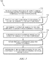
- a method 100 for detecting, inspecting, and repairing impact damage to a ceramic matrix composite component 24, 26, 28 assembled in a gas turbine engine 10 is shown in Fig. 3 .
- the gas turbine engine 10 includes a fan 12, a compressor 14, a combustor 16, and a turbine 18 as shown in Fig. 1 .
- the fan 12 is driven by the turbine 18 and provides thrust for propelling an aircraft.
- the compressor 14 compresses and delivers air to the combustor 16.
- the combustor 16 mixes fuel with the compressed air received from the compressor 14 and ignites the fuel.
- the hot, high-pressure products of the combustion reaction in the combustor 16 are directed into the turbine 18 to cause the turbine 18 to rotate about an axis 11 of the gas turbine engine 10 and drive the compressor 14 and the fan 12.
- the turbine 18 includes a turbine case 19, a plurality of static turbine vane assemblies 20 that are fixed relative to the axis 11, and a plurality of rotating bladed wheel assemblies 22 as suggested in Figs. 1 and 2 .
- the hot gases are conducted through the gas path 17 and interact with the bladed wheel assemblies 22 to cause the bladed wheel assemblies 22 to rotate about the axis 11.
- the turbine vane assembly 20 is arranged axially between the bladed wheel assemblies 22 and is positioned to direct the gases toward the downstream bladed wheel assembly 22 with a desired orientation.
- Both the static turbine vane assembly 20 and the rotating bladed wheel assemblies 22 may include components 24, 26, 28 made from ceramic matrix composite materials, i.e. vanes 24, blades 26, and/or seal segments 28.
- the ceramic matrix composite materials of the components 24, 26, 28 are adapted to withstand high temperatures.
- ceramic matrix composite components 24, 26, 28 may have a relatively low capability when subjected to impact from domestic or foreign object debris.
- the method 100 includes several steps that enable continued operation in case of impact events without adversely affecting operational safety.
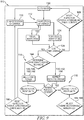
- the method 100 includes an inspection step 112, a repair step 114, and an assessment step 116 as shown in Figs. 3 and 6-9 .
- the inspection step 112 includes inspecting the ceramic matrix composite component 24, 26, 28 to determine an extent of damage 30 to the ceramic matrix composite component 24, 26, 28 and determining if the extent of damage 30 to the ceramic matrix composite component 24, 26, 28 is above a predetermined threshold.
- the repair step 114 includes determining a repair technique to repair the damage to the ceramic matrix composite component 24, 26, 28 based on the extent of damage 30 to the ceramic matrix composite component 24, 26, 28 and repairing the ceramic matrix composite component 24, 26, 28 using the repair technique.
- the assessment step 116 includes determining the repaired damage is below a predetermined residual severity limit so that the engine 10 may be cleared or permitted for flight.
- the method 100 may further include a detection step 110 as suggested in Fig. 3 .
- the detection step 110 includes detecting an impact event has occurred and inspection is suggested.
- the method 100 includes detecting damage to the component 24, 26, 28 using an engine health monitoring system, or EHM 86.
- the impact damage 30 may be detected using the engine health monitoring system 86 in some embodiments, or may be detected during a routine checkup of the engine 10 in other embodiments.
- the detection step 110 may include receiving a signal to the engine health monitoring system 86 included in the gas turbine engine 10 as suggested by block 110 in Fig. 3 .
- the signal is indicative of a detection of impact damage 30 to the ceramic matrix composite component 24, 26, 28 in the gas turbine engine 10.
- the signal is one of a temperature measurement and a pressure measurement within the gas turbine engine 10.
- the temperature and pressure may be measured by a sensor 88, 90 included in the engine health monitoring system 86.
- the signal measured by sensors 88, 90 may be other measurements in the engine e.g. shaft speeds, downstream temperatures, pipe pressure etc. that may subtly change as a result of the engine re-matching once the air system has been affected by the damage 30 to the component 24, 26, 28. In this way, the resolution of the engine health monitoring system algorithm may be improved.
- These other measurements may be used as calibration.
- other engine performance parameters may be used to calibrate the health monitoring system 86. For example, this may be similar to how a Turbine Casing Cooling (TCC) control system functions and damage on the seal segment 26 would likely affect the TCC system.
- TCC Turbine Casing Cooling
- the engine health monitoring system 86 Upon receipt of the signal, the engine health monitoring system 86 indicates the ceramic matrix composite component 24, 26, 28 may have impact damage 30 that could be inspected to determine the extent of damage 30 to the ceramic matrix composite component 24, 26, 28. After indication that the ceramic matrix composite component 24, 26, 28 may have impact damage 30, the method continues to the inspection step 112.
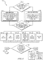
- the inspection step 112 begins by determining which type of inspection is to be used as indicated by block 120 as shown in Fig. 6 .
- the extent of damage 30 is inspected by one of a visual inspection 122 and a non-visual inspection 124.
- the visual inspection 122 includes visibly observing a physical characteristic of the ceramic matrix composite component 24, 26, 28, such as color, shape, or thermography.
- the non-visual inspection 124 includes measuring other non-visual characteristics of the component 24, 26, 28, such as stress levels in the component 24, 26, 28.
- the ceramic matrix composite component 24, 26, 28 includes a protective coating 42 that surrounds an outer surface 34 of the component 24, 26 as shown in Fig. 4 .
- the protective coating 42 includes a bond layer 48 and an environmental barrier coating layer 50 in the illustrative embodiment.
- the bond layer 48 contacts the outer surface 34 of the ceramic matrix composite component 24, 26 (outer surface 80 for the seal segment 28).
- the environmental barrier coating layer 50 is exposed hot gases flowing through a gas path 17 of the gas turbine engine 10.
- the environmental barrier coating layer 50 surrounds the bond layer 48.
- the protective coating 42 may only include the environmental barrier coating layer 50 such that the environmental barrier coating layer 50 surrounds the outer surface 34, 80 of the ceramic matrix composite component 24, 26, 28.
- Impact damage 30 to the protective coating 42 may cause cracks or spalling in the protective coating 42 that leaves the ceramic matrix composite materials of the component 24, 26, 28 exposed to hot gases in the gas path 17.
- the component 24, 26, 28 may be visually or non-visually inspected to determine the extent of damage 30 to the protective coating 42 and/or the ceramic matrix composite materials of the component 24, 26, 28.
- each component 24, 26, 28 has a high-risk zone, a medium-risk zone, a low-risk zone, and a no risk zone.
- the high-risk zone is more likely to endure impact events resulting in damage 30 to the component 24, 26, 28 and therefore is inspected thoroughly.
- the medium-risk zone is less likely to have damage compared to the high-risk zone, but still could be inspected.
- the low-risk zone is less likely to have damage compared to the medium-risk zone and may inspected less regularly then the high and medium-risk zones. However, the no risk zone could rarely be inspection as these areas are not in the gas path 17.
- the high-risk zone includes a leading edge 62 and a trailing edge 64 of the vane 24 as shown in Fig. 4 .
- the vane 24 includes an outer platform 52 that defines an outer boundary surface 56 of the gas path 17, an inner platform 54 spaced apart radially from the outer platform 52 to define an inner boundary surface 58 of the gas path 17, and an airfoil 60 that extends radially between the outer and inner platforms 52, 54 as shown in Fig 2 .
- the airfoil 60 is shaped to form the leading edge 62 and the trailing edge 64 spaced axially aft of the leading edge 62.
- the leading edge 62 and trailing edge 64 of the airfoil 60 are high at risk for damage.
- the medium-risk zone includes a pressure side 66 and a suction side 68 of the airfoil 60 included in the vane 24 as shown in Fig. 4 .
- the pressure and suction sides 66, 68 of the airfoil 60 extend axially between the leading and trailing edges 62, 64.
- the low-risk zone includes the outer and inner boundary surfaces 56, 58 of the platforms 52, 54 as shown in Fig. 2 .
- the no risk zone includes all surfaces of the vane 24 outside of the gas path 17. For instance, the outer and inner platforms 52, 54 radially inward and outward of the gas path 17.
- the blades 26 have an airfoil 72 with leading and trailing edges and pressure and suction sides as shown in Fig. 2 .
- the high-risk zone for blades 26 included in the bladed wheel assemblies 22 includes the leading edge and the trailing edge of the airfoil 72 included the blade 26, while the medium-risk zone includes the pressure and suction sides of the airfoil 72 included in the blade 26.
- the blade 26 further includes a root 70 that couples the blade 26 to a rotor disk 76 included in the bladed wheel assembly 22 and a platform 74 that extends circumferentially from the airfoil 72 as shown in Fig. 2 .
- the airfoil 72 that extends radially outward from the root 70 into the gas path 17.
- the low-risk zone includes a gas path surface 78 of the platform 74 as shown in Fig. 2 .
- the no risk zone includes the surfaces of the blade 26 radially inward and outward of the gas path 17.
- the root 70 is included in the no risk zone.
- the seal segment 28 may have only a low-risk zone, as the seal segment 28 is not directly in the gas path 17.
- the seal segment 28 forms a radially-inwardly facing surface 80 that is adjacent to the blades 26 to resist gases from passing over the blades 26 without interacting with the blades 26 as shown in Fig. 2 .
- the low-risk zone includes the radially-inwardly facing surface 80 of the seal segment 28.
- the visual inspection 122 includes at least one of comparing a shape, a color, and thermography of the ceramic matrix composite component 24, 26, 28 to a datum shape, a datum color, and a datum thermographic image of the ceramic matrix composite component 24, 26, 28. Based on the comparison, the method includes determining if the shape, color, and thermography of the ceramic matrix composite component 24, 26, 28 is indicative of impact damage 30 to the ceramic matrix composite component 24, 26, 28. In the illustrative embodiment, the shape, the color, and the thermography of the component 24, 26, 28 is visually inspected for each of the respective zones.
- the visual inspection step 122 may include analyzing the shape of the impact damage 30, i.e. central region of coating loss, potential substrate damage, and/or jagged edges.
- the shape of the impact damage 30 may be cone shaped if the ceramic marix composite component 24, 26, 28 was damaged on impact. In other instances, the damage 30 to the ceramic matrix composite component 24, 26, 28 may have progressed after intial impact, and may show in 'blended' edges of the ceramic matrix composite component 24, 26, 28. Other characteristics of the shape of the damage 30 may be the depth and/or the discontinuities of depth in the surface of the component 24, 26, 28.
- the visual inspection step 122 may also analyze the color contrast of the component 24, 26, 28.
- the protective coating 42 is initially a white coating on grey substrate. As damage to the protective coating 42 occurs, i.e. the coating 42 becomes contaminated, the color of the coating 42 will darken. If the substrate is visible, the substrate may lighted with oxidation.
- the visual inspection 122 of the ceramic matrix composite component 24, 26, 28 may be done using a borerscope or may be automated, such as with nano robots.
- the extent of damage 30 is detected physically by differences in color, contrast, shadowing, etc.
- the visual inscpection 122 may be automated by use of machine vision techniques such as feature edge detection or model matching.
- the visual inspection 122 of the ceramic matrix composite component 24, 26, 28 may also be done dimensionally, using a laser or blue/white light. The changes in shape and surface profile are used for the identification of the extent of damage 30. Dimensional inspection may be performed with conventional charged coupling devices (CCD) or complimentary metal oxide semiconductors (CMOS), i.e. videoscope devices using stereoscopic or 3D phase grating tips.
- CCD charged coupling devices
- CMOS complimentary metal oxide semiconductors
- the visual inspection 122 of the ceramic matrix composite component 24, 26, 28 may be done using passive and active thermographic imagining. Passive thermography inspection may use thermal gradients within the ceramic matrix composite component 24, 26, 28. Active thermography inspection may use a flash or purge fluid through a cooling system of the gas turbine engine 10.
- Both passive and active thermography inspections enable the visualization of material discontinuities.
- the material discontinuities may be indicative of coating or substrate delaminations, oblique cracking, thickness variations, and/or coating densification. This includes all heat activiation approaches including flash lights, lasers, ultrasonics, eddy currents etc.
- the visual inspection 122 of the ceramic matrix composite component 24, 26, 28 may also be done using flourescent penetrant inspection. Such an inspection method may be done with the component 24, 26, 28 in place in the engine 10. Flourescent penetratnt inspection may be leveraged to determine if there are any cracks within the protective coating 42 or ceramic matrix composite material of the component 24, 26, 28. During flourescent penetrant inspection, penetrant is placed on the surface via a borescsope, and allowed to infilitrate the cracks. Then a UV excitation source is used to identify regions of penetration.
- the visual insepection 122 of the ceramic matrix composite component 24, 26, 28 may be coating specific e.g. Raman Spectroscopy, UV fluorescence, Terahertz imaging. Using the difference in wave reflection and transmission properties (or vibrational spectra in the case of Raman), the coating composition and density maps may indicate damage, missing layers, phase transformation, etc.. In the case of terahertz, this will allow the determination of the material thickness and thus the extent of material recession.
- the visual inspection 122 of the ceramic matrix composite component 24, 26, 28 may also be done using hyperspectral imaging.
- the visual inspection 122 may elucidate different features than those typically observed with the eye.
- the hyperspectral imagining may improve the positive identification of surface asperities that may have surface contamination that minimizes contrast.
- the visual inspection 122 of the ceramic matrix composite component 24, 26, 28 may also be done using a capsule camera.
- the capsule camera may be attached to one of the blades 26 included in a bladed wheel assemlby 22 of the turbine 18 upstream or downstream of the desired component 24.
- Rotating bladed wheel assembly 22 enables full uninterrupted annulus inspection and may allow monocular, stereoscopic, or infrared inspection depending upon the sensor type.
- the non-visual inspection 124 includes comparing a stress level of the ceramic matrix composite component 24, 26, 28 to a predetermined allowable stress threshold and determining if the stress level is below the predetermined allowable stress threshold for the ceramic matrix composite component 24, 26, 28. If the stress level is below the predetermined allowable stress threshold, the component 24, 26, 28 is safe for use in the engine 10. If the stress level is above the predetermined allowable stress threshold, the component 24, 26, 28 is to be repaired before the component 24, 26, 28 may be used in the engine 10.
- the predetermined allowable stress threshold may vary around the ceramic matrix composite component 24, 26, 28, i.e. a higher threshold where the component 24, 26, 28 is less stressed in service.
- the component 24, 26, 28 may have a risk rating based on the influence of the damage 30 on the air system. For example, there may be a different result if the damage 30 is on the leading edge with a low-pressure differential between coolant and gas path, compared to damage 30 on the suction side 68 where there will be a large pressure difference.
- the non-visual inspection 124 of the ceramic matrix composite component 24, 26, 28 may be done using shearography. By inducing small amounts of stress into the component 24, 26, 28 (either through thermal or mechanical means), surface or subsurface discontinuities may be determined. The surface or subsurface discontinuities may include cracks in the protective coating 42 or ceramic matrix composite material of the component 24, 26, 28.
- the non-visual inspection 124 of the ceramic matrix composite component 24, 26, 28 may also be done using Ultrasonics or Eddy Current.
- the ultasonic waves or electrical eddy currents may be used to identify material damage or defects near the surface.
- Automated inspeciton approaches may be 'trained' on a catalogue of cermaic matrix composite impact test results, in addition to the damage rate expectations based on the high-risk, the medium-risk, and low-risk zones. If the inspection is manual, then the results should inform the inspection guidance.
- the inspection step 112 continues to determining the extent of damage 30 to the ceramic matrix composite component 24, 26, 28 as indicated by block 126 as shown in Fig. 6 .
- the selected inspection type i.e. visual 122 or non-visual 124
- the extent of damage 30 to the ceramic matrix composite component 24, 26, 28 is inspected to determine the extent of damage 30 to the ceramic matrix composite component 24, 26, 28.
- the vane assembly 20 includes the ceramic matrix composite component 24, or vane 24, and a metallic support structure 32 as shown in Figs. 2 , 4 , and 5 .
- the vane 24 forms the outer surface 34 that faces the gas path 17 of the engine 10 and an inner surface 36 that is shaped to form an interior cavity 38.
- the interior cavity 38 extends radially through the vane 24 and is sized to receive a spar 40 of the support structure 32.
- the spar 40 extends radially through the interior cavity 38 of the vane 24 to receive force loads applied to the vane 24 by gases flowing through the gas path 17.
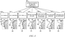
- the extent of damage 30 is determined based on the damage to the layers 48, 50 of the protective coating 42 and the ceramic matrix composite material of the component 24 as shown in Fig. 5 . As the extent of damage 30 progresses, the more adversely affected the vane assembly 20. For example, as opposed to cracking in the environmental barrier coating layer 50, holes 51 through the component 24 may expose the spar 40 of the metallic support structure 32, which may weaken the underlying support structure 32 of the vane assembly 20.
- the baseline is no damage to the ceramic matrix composite component 24.
- No damage to the ceramic matrix composite component 24 includes an intact protective coating 42 as indicated by block 130.
- Initial signs of impact damage 30 may include cracking in the environmental barrier coating layer 50 of the protective coating 42 of the ceramic matrix composite component 24 as shown in Fig. 5 . Cracking in the environmental barrier coating layer 50 without spalling in the environmental barrier coating layer 50 of the protective coating 42 is indicated by block 132.
- the extent of damage 30 may include spalling in the environmental barrier coating layer 50 of the protective coating 42 as shown in Fig. 5 . Spalling in the environmental barrier coating layer 50 without spalling in bond layer 48 of the protective coating 42 is indicated by block 134. In some embodiments, the block 134 may indicate spalling in the environmental barrier coating layer 50 without recession of the ceramic matrix composite material if the protective coating 42 does not include the bond layer 48.
- the damage may progress such the extent of damage 30 includes spalling in both the environmental barrier coating layer 50 and the bond layer 48 of the protective coating 42 as shown in Fig. 5 . Spalling in both layers 48, 50 without recession of the ceramic matrix composite material of the ceramic matrix composite component 24 is indicated by block 136.
- the extent of damage 30 includes recession of the ceramic matrix composite material of the ceramic matrix composite component 24 as shown in Fig. 5 .
- the extent of damage may also include oxidation of the ceramic matrix composite material in such instances. Recession of the ceramic matrix composite material of the component 24 without spalling in the ceramic matrix composite material of the ceramic matrix composite component 24 is indicated by block 138.
- the extent of damage 30 to the component 24 may include spalling in the ceramic matrix composite material of the ceramic matrix composite component 24 as shown in Fig. 5 . Spalling in the ceramic matrix composite material of the component 24 without a hole 51 extending through the ceramic matrix composite material into the interior cavity 38 of the ceramic matrix composite component 24 is indicated by block 140.
- the extent of damage 30 may include the hole 51 that extends through the protective coating 42 and ceramic matrix composite material of the ceramic matrix composite component 24.
- the hole 51 opens into the interior cavity 38 formed in the ceramic matrix composite component 24, exposing the spar 40 to the hot gases.
- Such an extent of damage is indicated by block 142.
- the method 100 may include post-processing of the inspection data.
- the post-processing may be done externally to the engine 10.
- the post-processing of the inspection data may be done to derive the predetermined residual severity limit of the component 24, 26, 28 and the associated acceptability of the residual severity of the damage 30.
- the predetermined threshold is the allowable damage to the ceramic matrix composite component 24, 26, 28 before the damage 30 begins to adversely affect the efficiency of the turbine 18.
- the predetermined threshold may be discontinuities or unevenness in the outer surface 34 of the vane 24. In other embodiments, the predetermined threshold may be minimal cracking in the environmental barrier coating layer 50 as indicated by block 132.
- the component 24, 26, 28 is acceptable for use and the method continues by clearing the engine 10 for re-air as indicated by block 158 in Fig. 6 .
- the engine health monitoring system 86 may be reset to detect the signal indicative of impact damage 30 to the ceramic matrix composite component 24, 26, 28 as suggested by block 160.
- the repair step 114 begins by determining the repair technique 146, 148, 150, 152, 154, 156 to be used to repair the ceramic matrix composite component 24, 26, 28 based on the extent of damage 30 as indicated by block 144.
- the repair technique 146, 148, 150, 152, 154, 156 may be one of a direct repair 146, 148, 150, 156 of the ceramic matrix composite material of the component 24, 26, 28 and an in-direct repair 152, 154 of the ceramic matrix composite material of the component 24, 26, 28.
- the method uses an in-direct repair 146 to repair the extent of damage 30 as shown in Fig. 7 .
- Such an in-direct repair 146 may include reapplying a portion of the environmental barrier coating layer 50 to a damaged area 82 of the environmental barrier coating layer 50.
- the in-direct repair 146 of the cracking in the environmental barrier coating layer 50 may include treating a surface 84 of the damaged area 82 of the environmental barrier coating layer 50 and reapplying a portion of the environmental barrier coating layer 50 that was treated.
- the method uses an in-direct repair 148 to repair the extent of damage 30 as shown in Fig. 7 .
- Such an in-direct repair includes reapplying a portion of the environmental barrier coating layer 50 to the damaged area 82 of the environmental barrier coating layer 50.
- the in-direct repair of the spalling in the environmental barrier coating layer 50 may include treating the surface 84 of the damaged area 82 of the environmental barrier coating layer 50 and reapplying a portion of the environmental barrier coating layer 50 that was treated.
- the method uses an in-direct repair 150 to repair the extent of damage 30 as shown in Fig. 7 .
- Such an in-direct repair technique 150 may include reapplying a portion of the protective coating 42 to the damaged area 82 of the protective coating 42.
- the in-direct repair 150 may include treating the surface 84 of the damaged area 82 of the protective coating 42 on the ceramic matrix composite component 24 and reapplying a portion of the protective coating 42 on the ceramic matrix composite component 24 that was treated.
- the in-direct repair 146, 148, 150 of the component 24 may be done using a variety of techniques to repair the extent of damage 30 to the component.
- the in-direct repair 146, 148, 150 of the different layers 48, 50 of the protective coating 42 may be done using combustion flame spray.
- the environmental barrier coating layer 50 and the bond layer 48 may be resprayed onto the component 24 using a powder fed Oxy-Acetylene torch.
- in-direct repair 146, 148, 150 of the protective coating 42 may instead be done using a slurry/sol environmental barrier coating patch repair.
- Application of ceramic slurries or environmental barrier coating precursor sols coupled with finishing operations in the green state may enable better surface profile control for environmental barrier coating patch repairs
- the in-direct repair 146, 148, 150 of the protective coating 42 may be done using a environmental barrier coating tape cast. Similar to the environmental barrier coating patch repair, a tape cast aproach may be easy to adhere and may potentially be UV or heat cured before firing to ceramacize the patch. Additionally, the in-direct repair of the protective coating 42 may be done using bond coat deposition.
- the bond coat deposition uses focused energy sources, ie. electron beam (E-Beam) or tungsten inert gas (TIG), while depositing Silicon through rod/wire feed or blown powder to form a bond coat patch with minimal oxidation.
- the in-direct repair 146, 148, 150 of the protective coating 42 may be done using cold spray of the bond layer 48 or the environmental barrier coating layer 50.
- Cold spraying the layers 48, 50 is a lower temperature approach, which leverages a highly accelerating gas flow to deposit material on the surface 84.
- Such a repair technique may be able to reduce levels of oxidation.
- the in-direct repair 146, 148, 150 may include blast cleaning the surface 84 before reapplying the any layers 48, 50 of the protective coating 42.
- the blast cleaning may be any one of plasma, chemical, laser, or other media to prep the surface 84.
- Such protective coatings 42 typically use surface preparation for good adherance.
- the method uses a direct repair 152 to repair the extent of damage 30 as shown in Fig. 7 .
- a direct repair 152 may include applying a ceramic matrix composite material patch to a damaged area 82 in the ceramic matrix composite material of the component 24.
- the direct repair 152 may include machining a surface 84 of the damaged area 82 in the ceramic matrix composite material of the ceramic matrix composite component 24 to smooth the surface of the ceramic matrix composite component 24.
- the method uses a direct repair 154 to repair the extent of damage 30 as shown in Fig. 7 .
- a direct repair 154 may include applying a ceramic matrix composite material patch to a damaged area 82 in the ceramic matrix composite material of the ceramic matrix composite component 24.
- the direct repair 154 may include machining a surface 84 of the damaged area 82 in the ceramic matrix composite material of the ceramic matrix composite component 24 to smooth the surface 84 of the ceramic matrix composite component 24.
- the direct repair 152, 154 of the component 24 may be done using a variety of techniques to repair the extent of damage 30 to the component 24.
- the direct repair 152, 154 of the ceramic matrix composite material may be done using a ceramic matrix composite patch repair. Application of surface tapes, slurries, or simply using a focused energy source to remelt the substrate.
- the direct repair 152, 154 of the ceramic matrix composite material may be done using ceramic matrix composite blending.
- the blending may be done by machining, either conventional, EDM, laser ablation, or Ultrasoni the surface 84 of the ceramic matrix composite material to remove the damaged area 82.
- the removal of the damaged area 82 produces a smooth surface profile for subsequent coating 42 application to improve adhesion and aerodynamic performance with minimized downstream turbulance.
- Other examples of direct repair techniques 152, 154 for repairing the ceramic matrix composite material may include expanding ceramic foam to fill discontinuities and/or gaps in the ceramic matrix composite material of the component 24.
- An expanding ceramic foam may be used to minimize the spread of damage 30 in the component 24.
- the ceramic foam may be subsequently remelted using a laser source to improve the density once the foam is in the correct location.
- the method may use one of an direct repair or an in-direct pair 156.
- a repair 156 may include sealing the hole 51 in the ceramic matrix composite material of the component 24 with ceramic foam. Filling the hole 51 may minimize ingress of hot gases into the interior cavity 38, or in the cases of the seal segment 28, the annular cavity 37.
- the repair 156 may include sealing the hole 51 in the component 24 with other materials to minimize ingress of hot gases into the cavity 38.
- the direct/in-direct repair 156 of the component 24 may be done using a variety of techniques to repair the extent of damage 30 to the component 24.
- the repair 156 for repairing the ceramic matrix composite material may include addative layer manufacturing to fill the hole 51 or gaps in the ceramic matrix composite material.
- the vane assembly 20 may be repaired by sealing the interior cavity 38 of the component 24. As such, combustion gas ingress into the interior cavity 38 may be minimized an enable sufficient flight cycles to the engine 10.
- the hole 51 may be filled using wire-fed direct laser deposition processes, and includes the use of dissimilar fillings which may be easier to deposit with the component 24 in the engine 10.
- the in-direct repair 156 may also include applying a thermal barrier coating to the spar 40 before sealing, which may also enable sufficient additional flight cycles to obtain the next shop vist.
- the thermal barrier coating may be applied using combustion flame spray onto the spar 40. In the event a hole 51 forms in the ceramic matrix composite material and the spar 40 is exposed, TBC may be applied through combustion flame spray to prevent additional damage zone growth in the event that the ceramic matrix composite patch or enviromental barrier coating patch fails.
- the repair 156 may be done by removing debris or material from sealing and/or cooling features in the component 24.
- trailing edge cooling holes (not shown) in the component 24 may be enlarged. As trailing edge cooling hole(s) increase in size, the leading edge discourager flow may increase to prevent leading edge ingestion. To do so, a potential repair may be to open the discourager holes, either by removing/maching material to enlarge discourager holes, removing/maching materail to make new discourager holes, and/or removing a pin to open discourager holes.
- Another potential repair may be to design the air system to be able to feed the upper limit of air, but until damage is detected, this air is vented overboard (or somewhere else in the enigne with minimal spoiling losses). Then a valve may be opened to redirect the air to the air system.
- another in-direct repair 156 may include increasing the size of impingement holes 41 included in the spar 40.
- the impingement holes 41 extend through the spar 40 fluidly connecting a cooling channel 44 of the support structure 32 to the interior cavity 38 of the vane 24 as suggested in Fig. 4 .
- the size of the impingement holes 41 may be increased in damaged vanes 24 to increase the flow of air in this area.
- Another in-direct repair 156 may be to increase leakage (dedicated feed) from upstream seal segment 28 of the bladed wheel assemlby 22. Increasing the leakage from the seal segment 28 may be done in a similar manner as removing the material to form the discourage holes.
- repair techniques 146, 148, 150, 152, 154, 156 may be used for other components, such as the blades 26 and the seal segments 28 of the bladed wheel assemblies 22.
- the repair techniques 146, 148, 150, 152, 154, 156 may be adapted for the specific component 26, 28.
- the assessment step 116 includes determining if the repaired damage to the ceramic matrix composite component 24, 26, 28 is below a predetermined residual severity limit as indicated by block 162.
- the predetermined residual severity limit is the allowable damage to the component 24, 26, 28 without it adversely affecting the performance of the vane assembly 20 and/or the gas turbine engine 10.
- the gas turbine engine 10 is cleared or permitted for flight as indicated by block 158. Once the gas turbine engine 10 is cleared or permitted for flight, the engine health monitoring system 86 may be reset to detect the signal indicative of impact damage 30 as indicated by block 160.
- the engine health monitoring system 86 may be reset based on the residual severity limit of the repaired damage. In this way, the engine health monitoring system 86 may detect impact damage 30 later as the residual severity of the damage 30 may affect the performance of the component 24, 26, 28.
- the ceramic matrix composite component 24, 26, 28 may be rejected as indicated by block 164.
- the gas turbine engine 10 may then be marked for overhaul to replace the component 24, 26, 28 or make other repairs as indicated by block 166.
- the ceramic matrix composite component 24, 26, 28 is one of a vane component 24, a blade component 26, a shroud component 28, a seal component, and combustion liner component.
- the method 100 may be adapted for any type of ceramic matrix composite component 24, 26, 28 in the gas turbine engine 10.
- the present disclosure relates to a method of mitigating the relatively low capability of ceramic matrix composite (CMC) components when subjected to impact from domestic or foreign object debris.
- Impact damage 30 is likely to be a significant life-cycle cost headwind, relative to metallic components. Therefore, suitable inspection and repair strategies and methods may be useful to enable continued operation in case of impact events without adversely affecting operational safety.
- Environmental barrier coatings may be used to protect the ceramic matrix composite materials of the components. In impact situations, recession mechanism that propagates damage if the coating is removed/spalled
- CMC components 24, 26, 28 may be less tolerant to impact events.
- the impact will typically be caused by domestic object debris.
- the other failure modes may result in EBC spallation and/or holing in the ceramic matrix composite material.
- the increased disc temperature may occur because the cooling flows are disrupted and other elements of the structure become hotter. Increased disc temperature may also be caused hot gases directly contacting the structure where the pressure gradient permits hot gas ingress. This can open seal clearances for example blade rim seals due to axial deflection of the vane assembly 20 such that hot gas ingress into a disk cavity between the blade stages cannot be prevented
- This submission relates to a series of mitigations, to initially determine that the CMC components 24, 26, 28 have been damaged and then if appropriate, to repair them.
- the steps of the mitigation method are shown in Figs. 3 and 6-9 .
- the susceptable areas of the CMC component 24, 26, 28 change depending on the local boundary conditions, i.e. temperature, pressure, velocity, stress state.
- the suseptable areas may also change according to the potential orientation of impact debris travelling in the gas path 17. Insepction and repair capabilities may be tailored to maximise capabilitiesiiy.
- the specifics captured here mainly relate to a vane assembly 20 in the turbine 18 of the gas turibne engine 10, but the method 100 may be applied to any ceramic matrix composite component, like the blade 26 and/or the seal segment 28.
- Inspection and detection may not be undertaken immediately after an impact event, therefore, the damage assessed will be on the spectrum shown in Fig. 5 .
- the inspection, detection, and repair requirements will change across the damage spectrum.
- the engine health monitoring system 86 may be configured to direct the inspection of the ceramic matrix composite component 24, 26, 28 assembled in a gas turbine engine 10 to determine the extent of damage to the ceramic matrix composite component 24, 26, 28.
- the engine health monitoring 86 system may inspect the ceramic matrix composite component 24, 26, 28 assembled in a gas turbine engine using the sensors 86, 88 to determine the extent of damage 30 to the ceramic matrix composite component 24, 26, 28.
- the engine health monitoring system 86 may determine if the extent of damage 30 to the ceramic matrix composite component 24, 26, 28 is above a predetermined threshold.
- the engine health monitoring system 86 may be configured to determine the repair technique to repair the damage 30 to the ceramic matrix composite component 24, 26, 28 based on the extent of damage 30 to the component 24, 26, 28.
- the ceramic matrix composite component 24, 26, 28 may be repaired using the repair technique determined by the engine health monitoring system 86.
- the engine health monitoring system 86 may be configured to determine if the repaired damage to the ceramic matrix composite component 24, 26, 28 is below a predetermined residual severity limit. If the repaired damage to the ceramic matrix composite component 24, 26, 28 is below the predetermined residual severity limit, the engine health monitoring system 86 may clear the gas turbine engine 10 for flight.
- the engine health monitoring system 86 is configured to receive the signal indicative of a detection of impact damage 30 to the ceramic matrix composite component 24, 26, 28 in the gas turbine engine 10. If the extent of damage is below the predetermined threshold, the engine health monitoring system 86 may reset to detect the signal indicative of impact damage 30 to the ceramic matrix composite component 24, 26, 28.
- the signal may be one of a temperature measurement and a pressure measurement within the gas turbine engine 10.
- the signal may be measured by sensors 88, 90 included in the engine health monitoring system 86.
- the ceramic matrix composite component 24, 26, 28 is one of a vane component, a blade component, a shroud component, a seal component, and combustion liner component.
- the engine health monitoring algorithm should assess the step change relative to modelled baseline, i.e. same number for every engine, the step change relative to engine specific measured baseline, i.e. different number for every engine, and the trending change with rate of change beyond given limits to determine if an impact event has occurred.
- the baseline may be reset after a thorough inspection.
- the 'proactive' inspection interval may vary depending on seveal factors. For example, impact events are stochastic and therefore insepections may be repeated on a periodic basis, related to the time taken to generate a safety concern. Additionally, recesion is driven by temperature, pressure, water vapour content, and velocity, so the inspection procedure/timing may be different for each ceramic matrix composite component 24, 26, 28 in the engine 10.
- Debris may come from the combustion module or other high pressure turbine compoentns, so further downstream parts may have more impact events. Sensitivity to repair, i.e. if the component 24, 26, 28 may be easier and/or more likely succeed, the less the damage has propagated and thus it may be advatageous to inspect the component 24, 26, 28 more frequently.
- the damage rate on the component 24, 26, 28 may vary. Post-repair on the component 24, 26, 28, repeat inspections may be completed more frequently.
Landscapes
- Engineering & Computer Science (AREA)
- Chemical & Material Sciences (AREA)
- Mechanical Engineering (AREA)
- General Engineering & Computer Science (AREA)
- Materials Engineering (AREA)
- Ceramic Engineering (AREA)
- Organic Chemistry (AREA)
- Structural Engineering (AREA)
- Combustion & Propulsion (AREA)
- Physics & Mathematics (AREA)
- General Physics & Mathematics (AREA)
- Composite Materials (AREA)
- Turbine Rotor Nozzle Sealing (AREA)
Abstract
Description
- The present disclosure relates generally to gas turbine engines and more specifically to ceramic matrix composite components for use with gas turbine engines.
- Gas turbine engines are used to power aircraft, watercraft, power generators, and the like. Gas turbine engines typically include a compressor, a combustor, and a turbine. The compressor compresses air drawn into the engine and delivers high-pressure air to the combustor. In the combustor, fuel is mixed with the high-pressure air and is ignited. Products of the combustion reaction in the combustor are directed into the turbine where work is extracted to drive the compressor and, sometimes, an output shaft. Left-over products of the combustion are exhausted out of the turbine and may provide thrust in some applications.
- Products of the combustion reaction directed into the turbine are conducted toward airfoils included in stationary vanes and rotating blades of the turbine. The airfoils, shrouds, and combustor components are often made from high-temperature resistant materials and/or are actively cooled by supplying relatively cool air to the vanes and blades due to the high temperatures of the combustion products. To this end, some airfoils for vanes and blades, shrouds, seals, and combustor components are incorporating composite materials adapted to withstand very high temperatures. However, ceramic matrix composite materials have a relatively low capability when subjected to impact from domestic or foreign object debris compared to components made from metallic materials.
- The present disclosure provides a method for inspecting a ceramic matrix composite assembled in a gas turbine engine, as set out in the appended claims.
- A method may include inspecting a ceramic matrix composite component assembled in a gas turbine engine to determine an extent of damage to the ceramic matrix composite component and determining if the extent of damage to the ceramic matrix composite component is above a predetermined threshold. The method may also include determining a repair technique to repair the damage to the ceramic matrix composite component based on the extent of damage to the ceramic matrix composite component and repairing the ceramic matrix composite component using the repair technique.
- In some embodiments, the method may further include determining if the repaired damage to the ceramic matrix composite component is below a predetermined residual severity limit. If the repaired damage to the ceramic matrix composite component is below the predetermined residual severity limit, the method may further include clearing the gas turbine engine for flight.
- In some embodiments, the method may further include receiving a signal to an engine health monitoring system included in the gas turbine engine. The signal may be indicative of a detection of impact damage to the ceramic matrix composite component in the gas turbine engine. If the extent of damage is below the predetermined threshold, the method may further include resetting the engine health monitoring system to detect the signal indicative of impact damage to the ceramic matrix composite component.
- In some embodiments, the repair technique may include one of a direct repair and an in-direct repair of the ceramic matrix composite material of the ceramic matrix composite component. In some embodiments, the inspection step may include one of a visual inspection and a non-visual inspection of the extent of damage to the ceramic matrix composite component.
- In some embodiments, the visual inspection may include at least comparing a shape of the ceramic matrix composite component to a datum shape, comparing a color of the ceramic matrix composite component to a datum color, and comparing a thermographic image of the ceramic matrix composite component to a datum thermographic image. The visual inspection may further include determining if the shape, color, and thermography of the ceramic matrix composite component is indicative of impact damage to the ceramic matrix composite component.
- In some embodiments, the non-visual inspection may include comparing a stress level of the ceramic matrix composite component to a predetermined allowable stress threshold. The non-visual inspection may further include determining if the stress level is below the predetermined allowable stress threshold for the ceramic matrix composite component.
- In some embodiments, the ceramic matrix composite component may include a protective coating. The protective coating may surround an outer surface of the ceramic matrix composite component.
- In some embodiments, the protective coating may have a bond layer and an environmental barrier coating. The bond layer may contact the outer surface of the ceramic matrix composite component. The environmental barrier coating layer may surround the bond layer and may be exposed hot gases flowing through a primary flow path of the gas turbine engine.
- In some embodiments, the repair technique may include an in-direct repair of the ceramic matrix composite material of the ceramic matrix composite component. The repair technique may include the in-direct repair if the extent of damage to the ceramic matrix composite component includes cracking in the environmental barrier coating layer of the protective coating of the ceramic matrix composite component without spalling in the environmental barrier coating layer of the protective coating. The repair technique may include the in-direct repair if the extent of damage to the ceramic matrix composite component includes spalling in the environmental barrier coating layer of the protective coating without spalling in the bond layer of the protective coating.
- In some embodiments, the in-direct repair may include reapplying a portion of the environmental barrier coating layer to a damaged area of the environmental barrier coating layer of the protective coating on the ceramic matrix composite component. The in-direct repair may include treating a surface of the damaged area of the environmental barrier coating layer and reapplying a portion of the environmental barrier coating layer of the protective coating on the ceramic matrix composite component that was treated.
- In some embodiments, the repair technique may include an in-direct repair of the ceramic matrix composite material of the ceramic matrix composite component. The repair technique may include the in-direct repair if the extent of damage to the ceramic matrix composite component includes spalling in both the environmental barrier coating layer and the bond layer of the protective coating without recession of the ceramic matrix composite material of the ceramic matrix composite component.
- In some embodiments, the in-direct repair may include reapplying a portion of the protective coating to a damaged area of the protective coating. The in-direct repair may include treating a surface of the damaged area of the protective coating on the ceramic matrix composite component and reapplying a portion of the protective coating on the ceramic matrix composite component that was treated.
- In some embodiments, the repair technique may include a direct repair of the ceramic matrix composite material of the ceramic matrix composite component. The repair technique may include the direct repair if the extent of damage to the ceramic matrix composite component includes recession of the ceramic matrix composite material of the ceramic matrix composite component without spalling in the ceramic matrix composite material of the ceramic matrix composite component. The repair technique may include the direct repair if the extent of damage to the ceramic matrix composite component includes spalling in the ceramic matrix composite material of the ceramic matrix composite component without a hole extending through the ceramic matrix composite material into an interior cavity of the ceramic matrix composite component.
- In some embodiments, the direct repair may include applying a ceramic matrix composite material patch to a damaged area in the ceramic matrix composite material of the ceramic matrix composite component. The direct repair may include machining a surface of the damaged area in the ceramic matrix composite material of the ceramic matrix composite component to smooth the surface of the ceramic matrix composite component.
- In some embodiments, the repair technique may include one of a direct repair of the ceramic matrix composite material of the ceramic matrix composite component and an in-direct repair of the ceramic matrix composite material of the ceramic matrix composite component. The repair technique may include one of the direct repair and the in-direct repair if the extent of damage to the ceramic matrix composite component includes a hole that extends through the protective coating and ceramic matrix composite material of the ceramic matrix composite component and opens into an interior cavity formed in the ceramic matrix composite component.
- In some embodiments, the in-direct repair may include sealing the hole in the ceramic matrix composite material of the ceramic matrix composite component to minimize ingress of hot gases into the interior cavity. The in-direct repair may include applying the protective coating to a surface of a metallic component located in the interior cavity of the ceramic matrix composite component.
- In some embodiments, the method may further include receiving a signal to an engine health monitoring system included in the gas turbine engine. The signal may be indicative of a detection of impact damage to the ceramic matrix composite component in the gas turbine engine.
- In some embodiments, the signal may be one of a temperature measurement and a pressure measurement within the gas turbine engine. The signal may be measured by a sensor included in the engine health monitoring system. In some embodiments, the ceramic matrix composite component is one of a vane component, a blade component, a shroud component, a seal component, and combustion liner component.
- According to another aspect of the present disclosure, a gas turbine engine may include a turbine and an engine health monitoring system. The turbine may include a ceramic matrix composite component arranged to extend circumferentially at least partway about an axis and a metallic component arranged circumferentially around the ceramic matrix composite component. The engine health monitoring system may be configured to monitor damage to the ceramic matrix composite component in the gas turbine engine.
- In some embodiments, the engine health monitoring system may be configured to inspect a ceramic matrix composite component assembled in a gas turbine engine to determine an extent of damage to the ceramic matrix composite component. In some embodiments, the engine health monitoring system may be configured to direct inspection of the ceramic matrix composite component assembled in a gas turbine engine to determine an extent of damage to the ceramic matrix composite component. The engine health monitoring system may determine if the extent of damage to the ceramic matrix composite component is above a predetermined threshold.
- In some embodiments, the engine health monitoring system may be configured to determine a repair technique to repair the damage to the ceramic matrix composite component based on the extent of damage to the ceramic matrix composite component. The ceramic matrix composite component may be repaired using the repair technique determined by the engine health monitoring system.
- In some embodiments, after the ceramic matrix composite material is repaired, the engine health monitoring system may be configured to determine if the repaired damage to the ceramic matrix composite component is below a predetermined residual severity limit. If the repaired damage to the ceramic matrix composite component is below the predetermined residual severity limit, the engine health monitoring system may clear the gas turbine engine for flight.
- In some embodiments, the engine health monitoring system is configured to receive a signal. The signal may be indicative of a detection of impact damage to the ceramic matrix composite component in the gas turbine engine. If the extent of damage is below the predetermined threshold, the engine health monitoring system may reset to detect the signal indicative of impact damage to the ceramic matrix composite component.
- In some embodiments, the signal may be one of a temperature measurement and a pressure measurement within the gas turbine engine. The signal may be measured by a sensor included in the engine health monitoring system. In some embodiments, the ceramic matrix composite component is one of a vane component, a blade component, a shroud component, a seal component, and combustion liner component.
- In some embodiments, the inspection step may include one of a visual inspection and a non-visual inspection of the extent of damage to the ceramic matrix composite component. In some embodiments, the visual inspection may include at least comparing a shape of the ceramic matrix composite component to a datum shape, comparing a color of the ceramic matrix composite component to a datum color, and comparing a thermographic image of the ceramic matrix composite component to a datum thermographic image. The visual inspection may further include determining if the shape, color, and thermography of the ceramic matrix composite component is indicative of impact damage to the ceramic matrix composite component.
- In some embodiments, the non-visual inspection may include comparing a stress level of the ceramic matrix composite component to a predetermined allowable stress threshold. The non-visual inspection may further include determining if the stress level is below the predetermined allowable stress threshold for the ceramic matrix composite component.
- In some embodiments, the repair technique may include an in-direct repair of the ceramic matrix composite material of the ceramic matrix composite component. In some embodiments, the repair technique may include a direct repair of the ceramic matrix composite material of the ceramic matrix composite component.
- These and other features of the present disclosure will become more apparent from the following description of the illustrative embodiments.
-
-
Fig. 1 is a cutaway view of a gas turbine engine that includes a fan, a compressor, a combustor, and a turbine, the turbine including rotating wheel assemblies configured to rotate about an axis of the engine and static turbine vane assemblies configured to direct air into downstream rotating wheel assemblies; -
Fig. 2 is a section view of a portion of the turbine included in the gas turbine engine ofFig. 1 showing each static turbine vane assembly includes a ceramic matrix composite vane and a metallic vane support that couples the ceramic matrix composite vane to a turbine case; -
Fig. 3 is a diagrammatic view of a method of monitoring damage to a component made of ceramic matrix composite material included in one of the rotating wheel assemblies and the static turbine vane assembly ofFig. 2 showing the method includes (i) inspecting the ceramic matrix composite component to determine an extent of damage to the component, (ii) determining if the extent of damage to the ceramic matrix composite component is above a predetermined threshold, (iii) determining a repair technique to repair the damage to the ceramic matrix composite component based on the extent of damage to the component, and (iv) repairing the ceramic matrix composite component using the repair technique; -
Fig. 4 is a section view of the static turbine vane ring ofFig. 2 taking along line 4-4 showing the ceramic matrix composite vane has a protective coating that surrounds an outer surface of the ceramic matrix composite vane; -
Fig. 5 is a diagrammatic view of different stages of damage to the protective coating and the ceramic matrix composite material of the ceramic matrix composite vane; -
Fig. 6 is a diagrammatic view of the inspecting step ofFig. 3 showing the inspecting step includes one of a visual inspection and a non-visual inspection of the extent of damage to the ceramic matrix composite component; -
Fig. 7 is a diagrammatic view of the repair step ofFig. 3 showing the repair technique includes one of a direct repair of the ceramic matrix composite material of the ceramic matrix composite component and an in-direct repair of the ceramic matrix composite material of the ceramic matrix composite component based on the extent of damage to the component; -
Fig. 8 is a diagrammatic view of the assessment step ofFig. 3 showing the assessment step includes determining if the repaired damaged to the ceramic matrix composite component is below a predetermined residual severity limit; and -
Fig. 9 is a diagrammatic view of the method ofFig. 3 showing the method includes a detection step along with the inspection, repair, and assessment steps. - For the purposes of promoting an understanding of the principles of the disclosure, reference will now be made to a number of illustrative embodiments illustrated in the drawings and specific language will be used to describe the same.
- A
method 100 for detecting, inspecting, and repairing impact damage to a ceramicmatrix composite component gas turbine engine 10 is shown inFig. 3 . Thegas turbine engine 10 includes afan 12, acompressor 14, acombustor 16, and aturbine 18 as shown inFig. 1 . Thefan 12 is driven by theturbine 18 and provides thrust for propelling an aircraft. Thecompressor 14 compresses and delivers air to thecombustor 16. Thecombustor 16 mixes fuel with the compressed air received from thecompressor 14 and ignites the fuel. The hot, high-pressure products of the combustion reaction in thecombustor 16 are directed into theturbine 18 to cause theturbine 18 to rotate about anaxis 11 of thegas turbine engine 10 and drive thecompressor 14 and thefan 12. - The
turbine 18 includes aturbine case 19, a plurality of staticturbine vane assemblies 20 that are fixed relative to theaxis 11, and a plurality of rotating bladedwheel assemblies 22 as suggested inFigs. 1 and 2 . The hot gases are conducted through thegas path 17 and interact with thebladed wheel assemblies 22 to cause thebladed wheel assemblies 22 to rotate about theaxis 11. Theturbine vane assembly 20 is arranged axially between thebladed wheel assemblies 22 and is positioned to direct the gases toward the downstreambladed wheel assembly 22 with a desired orientation. - Both the static
turbine vane assembly 20 and the rotatingbladed wheel assemblies 22 may includecomponents vanes 24,blades 26, and/or sealsegments 28. The ceramic matrix composite materials of thecomponents matrix composite components - Compared to components made from metallic materials, ceramic
matrix composite components impact damage 30 to the ceramicmatrix composite component Fig. 5 . Themethod 100 includes several steps that enable continued operation in case of impact events without adversely affecting operational safety. - The
method 100 includes aninspection step 112, arepair step 114, and anassessment step 116 as shown inFigs. 3 and6-9 . Theinspection step 112 includes inspecting the ceramicmatrix composite component damage 30 to the ceramicmatrix composite component damage 30 to the ceramicmatrix composite component repair step 114 includes determining a repair technique to repair the damage to the ceramicmatrix composite component damage 30 to the ceramicmatrix composite component matrix composite component assessment step 116 includes determining the repaired damage is below a predetermined residual severity limit so that theengine 10 may be cleared or permitted for flight. - In the illustrative embodiment, the
method 100 may further include adetection step 110 as suggested inFig. 3 . Thedetection step 110 includes detecting an impact event has occurred and inspection is suggested. Rather than routinely inspecting the ceramicmatrix composite components damage 30 to the ceramic matrix composite material, themethod 100 includes detecting damage to thecomponent EHM 86. - The
impact damage 30 may be detected using the enginehealth monitoring system 86 in some embodiments, or may be detected during a routine checkup of theengine 10 in other embodiments. Thedetection step 110 may include receiving a signal to the enginehealth monitoring system 86 included in thegas turbine engine 10 as suggested byblock 110 inFig. 3 . The signal is indicative of a detection ofimpact damage 30 to the ceramicmatrix composite component gas turbine engine 10. - In some embodiments, the signal is one of a temperature measurement and a pressure measurement within the
gas turbine engine 10. The temperature and pressure may be measured by asensor 88, 90 included in the enginehealth monitoring system 86. - In other embodiments, the signal measured by
sensors 88, 90 may be other measurements in the engine e.g. shaft speeds, downstream temperatures, pipe pressure etc. that may subtly change as a result of the engine re-matching once the air system has been affected by thedamage 30 to thecomponent health monitoring system 86. For example, this may be similar to how a Turbine Casing Cooling (TCC) control system functions and damage on theseal segment 26 would likely affect the TCC system. - Upon receipt of the signal, the engine
health monitoring system 86 indicates the ceramicmatrix composite component impact damage 30 that could be inspected to determine the extent ofdamage 30 to the ceramicmatrix composite component matrix composite component impact damage 30, the method continues to theinspection step 112. - Before the extent of
damage 30 is inspected, theinspection step 112 begins by determining which type of inspection is to be used as indicated byblock 120 as shown inFig. 6 . The extent ofdamage 30 is inspected by one of avisual inspection 122 and anon-visual inspection 124. Thevisual inspection 122 includes visibly observing a physical characteristic of the ceramicmatrix composite component non-visual inspection 124 includes measuring other non-visual characteristics of thecomponent component - In the illustrative embodiment, the ceramic
matrix composite component protective coating 42 that surrounds anouter surface 34 of thecomponent Fig. 4 . Theprotective coating 42 includes abond layer 48 and an environmentalbarrier coating layer 50 in the illustrative embodiment. Thebond layer 48 contacts theouter surface 34 of the ceramicmatrix composite component 24, 26 (outer surface 80 for the seal segment 28). The environmentalbarrier coating layer 50 is exposed hot gases flowing through agas path 17 of thegas turbine engine 10. - In the illustrative embodiment, the environmental
barrier coating layer 50 surrounds thebond layer 48. In other embodiments, theprotective coating 42 may only include the environmentalbarrier coating layer 50 such that the environmentalbarrier coating layer 50 surrounds theouter surface matrix composite component -
Impact damage 30 to theprotective coating 42 may cause cracks or spalling in theprotective coating 42 that leaves the ceramic matrix composite materials of thecomponent gas path 17. As such, thecomponent damage 30 to theprotective coating 42 and/or the ceramic matrix composite materials of thecomponent - In both visual and
non-visual inspections component component damage 30 to thecomponent gas path 17. - For
vanes 24 included in thevane assemblies 20, the high-risk zone includes aleading edge 62 and a trailingedge 64 of thevane 24 as shown inFig. 4 . Thevane 24 includes anouter platform 52 that defines anouter boundary surface 56 of thegas path 17, aninner platform 54 spaced apart radially from theouter platform 52 to define aninner boundary surface 58 of thegas path 17, and anairfoil 60 that extends radially between the outer andinner platforms Fig 2 . Theairfoil 60 is shaped to form the leadingedge 62 and the trailingedge 64 spaced axially aft of the leadingedge 62. The leadingedge 62 and trailingedge 64 of theairfoil 60 are high at risk for damage. - The medium-risk zone includes a
pressure side 66 and asuction side 68 of theairfoil 60 included in thevane 24 as shown inFig. 4 . The pressure andsuction sides airfoil 60 extend axially between the leading and trailingedges - The low-risk zone includes the outer and inner boundary surfaces 56, 58 of the
platforms Fig. 2 . The no risk zone includes all surfaces of thevane 24 outside of thegas path 17. For instance, the outer andinner platforms gas path 17. - Similar to the
vane 24, theblades 26 have anairfoil 72 with leading and trailing edges and pressure and suction sides as shown inFig. 2 . The high-risk zone forblades 26 included in thebladed wheel assemblies 22 includes the leading edge and the trailing edge of theairfoil 72 included theblade 26, while the medium-risk zone includes the pressure and suction sides of theairfoil 72 included in theblade 26. - The
blade 26 further includes aroot 70 that couples theblade 26 to arotor disk 76 included in thebladed wheel assembly 22 and aplatform 74 that extends circumferentially from theairfoil 72 as shown inFig. 2 . Theairfoil 72 that extends radially outward from theroot 70 into thegas path 17. - The low-risk zone includes a gas path surface 78 of the
platform 74 as shown inFig. 2 . The no risk zone includes the surfaces of theblade 26 radially inward and outward of thegas path 17. Theroot 70 is included in the no risk zone. - For
seal segments 28 included in thebladed wheel assemblies 22, theseal segment 28 may have only a low-risk zone, as theseal segment 28 is not directly in thegas path 17. Theseal segment 28 forms a radially-inwardly facingsurface 80 that is adjacent to theblades 26 to resist gases from passing over theblades 26 without interacting with theblades 26 as shown inFig. 2 . The low-risk zone includes the radially-inwardly facingsurface 80 of theseal segment 28. - The
visual inspection 122 includes at least one of comparing a shape, a color, and thermography of the ceramicmatrix composite component matrix composite component matrix composite component impact damage 30 to the ceramicmatrix composite component component - The
visual inspection step 122 may include analyzing the shape of theimpact damage 30, i.e. central region of coating loss, potential substrate damage, and/or jagged edges. The shape of theimpact damage 30 may be cone shaped if the ceramicmarix composite component damage 30 to the ceramicmatrix composite component matrix composite component damage 30 may be the depth and/or the discontinuities of depth in the surface of thecomponent - The
visual inspection step 122 may also analyze the color contrast of thecomponent protective coating 42 is initially a white coating on grey substrate. As damage to theprotective coating 42 occurs, i.e. thecoating 42 becomes contaminated, the color of thecoating 42 will darken. If the substrate is visible, the substrate may lighted with oxidation. - The
visual inspection 122 of the ceramicmatrix composite component damage 30 is detected physically by differences in color, contrast, shadowing, etc. Thevisual inscpection 122 may be automated by use of machine vision techniques such as feature edge detection or model matching. - The
visual inspection 122 of the ceramicmatrix composite component damage 30. Dimensional inspection may be performed with conventional charged coupling devices (CCD) or complimentary metal oxide semiconductors (CMOS), i.e. videoscope devices using stereoscopic or 3D phase grating tips. - The
visual inspection 122 of the ceramicmatrix composite component matrix composite component gas turbine engine 10. - Both passive and active thermography inspections enable the visualization of material discontinuities. The material discontinuities may be indicative of coating or substrate delaminations, oblique cracking, thickness variations, and/or coating densification. This includes all heat activiation approaches including flash lights, lasers, ultrasonics, eddy currents etc.
- The
visual inspection 122 of the ceramicmatrix composite component component engine 10. Flourescent penetratnt inspection may be leveraged to determine if there are any cracks within theprotective coating 42 or ceramic matrix composite material of thecomponent - The
visual insepection 122 of the ceramicmatrix composite component - The
visual inspection 122 of the ceramicmatrix composite component visual inspection 122 may elucidate different features than those typically observed with the eye. The hyperspectral imagining may improve the positive identification of surface asperities that may have surface contamination that minimizes contrast. - The
visual inspection 122 of the ceramicmatrix composite component blades 26 included in abladed wheel assemlby 22 of theturbine 18 upstream or downstream of the desiredcomponent 24. Rotatingbladed wheel assembly 22 enables full uninterrupted annulus inspection and may allow monocular, stereoscopic, or infrared inspection depending upon the sensor type. - The
non-visual inspection 124 includes comparing a stress level of the ceramicmatrix composite component matrix composite component component engine 10. If the stress level is above the predetermined allowable stress threshold, thecomponent component engine 10. - In the illustrative embodiment, the predetermined allowable stress threshold may vary around the ceramic
matrix composite component component component damage 30 on the air system. For example, there may be a different result if thedamage 30 is on the leading edge with a low-pressure differential between coolant and gas path, compared todamage 30 on thesuction side 68 where there will be a large pressure difference. - The
non-visual inspection 124 of the ceramicmatrix composite component component protective coating 42 or ceramic matrix composite material of thecomponent - The
non-visual inspection 124 of the ceramicmatrix composite component - Automated inspeciton approaches may be 'trained' on a catalogue of cermaic matrix composite impact test results, in addition to the damage rate expectations based on the high-risk, the medium-risk, and low-risk zones. If the inspection is manual, then the results should inform the inspection guidance.
- Once the
inspection type inspection step 112 continues to determining the extent ofdamage 30 to the ceramicmatrix composite component block 126 as shown inFig. 6 . Using the selected inspection type, i.e. visual 122 or non-visual 124, the extent ofdamage 30 to the ceramicmatrix composite component damage 30 to the ceramicmatrix composite component - Turning again to the
vane assembly 20, thevane assembly 20 includes the ceramicmatrix composite component 24, orvane 24, and ametallic support structure 32 as shown inFigs. 2 ,4 , and5 . Thevane 24 forms theouter surface 34 that faces thegas path 17 of theengine 10 and aninner surface 36 that is shaped to form aninterior cavity 38. Theinterior cavity 38 extends radially through thevane 24 and is sized to receive aspar 40 of thesupport structure 32. Thespar 40 extends radially through theinterior cavity 38 of thevane 24 to receive force loads applied to thevane 24 by gases flowing through thegas path 17. - The extent of
damage 30 is determined based on the damage to thelayers protective coating 42 and the ceramic matrix composite material of thecomponent 24 as shown inFig. 5 . As the extent ofdamage 30 progresses, the more adversely affected thevane assembly 20. For example, as opposed to cracking in the environmentalbarrier coating layer 50, holes 51 through thecomponent 24 may expose thespar 40 of themetallic support structure 32, which may weaken theunderlying support structure 32 of thevane assembly 20. - As shown in
Fig. 5 , the baseline is no damage to the ceramicmatrix composite component 24. No damage to the ceramicmatrix composite component 24 includes an intactprotective coating 42 as indicated byblock 130. - Initial signs of
impact damage 30 may include cracking in the environmentalbarrier coating layer 50 of theprotective coating 42 of the ceramicmatrix composite component 24 as shown inFig. 5 . Cracking in the environmentalbarrier coating layer 50 without spalling in the environmentalbarrier coating layer 50 of theprotective coating 42 is indicated byblock 132. - As the damage progresses, the extent of
damage 30 may include spalling in the environmentalbarrier coating layer 50 of theprotective coating 42 as shown inFig. 5 . Spalling in the environmentalbarrier coating layer 50 without spalling inbond layer 48 of theprotective coating 42 is indicated byblock 134. In some embodiments, theblock 134 may indicate spalling in the environmentalbarrier coating layer 50 without recession of the ceramic matrix composite material if theprotective coating 42 does not include thebond layer 48. - With the
bond layer 48 exposed, the damage may progress such the extent ofdamage 30 includes spalling in both the environmentalbarrier coating layer 50 and thebond layer 48 of theprotective coating 42 as shown inFig. 5 . Spalling in bothlayers matrix composite component 24 is indicated byblock 136. - As the ceramic matrix composite material is exposed to the hot gases in the
gas path 17, the extent ofdamage 30 includes recession of the ceramic matrix composite material of the ceramicmatrix composite component 24 as shown inFig. 5 . The extent of damage may also include oxidation of the ceramic matrix composite material in such instances. Recession of the ceramic matrix composite material of thecomponent 24 without spalling in the ceramic matrix composite material of the ceramicmatrix composite component 24 is indicated byblock 138. - The extent of
damage 30 to thecomponent 24 may include spalling in the ceramic matrix composite material of the ceramicmatrix composite component 24 as shown inFig. 5 . Spalling in the ceramic matrix composite material of thecomponent 24 without ahole 51 extending through the ceramic matrix composite material into theinterior cavity 38 of the ceramicmatrix composite component 24 is indicated byblock 140. - As the damage progresses, the extent of
damage 30 may include thehole 51 that extends through theprotective coating 42 and ceramic matrix composite material of the ceramicmatrix composite component 24. Thehole 51 opens into theinterior cavity 38 formed in the ceramicmatrix composite component 24, exposing thespar 40 to the hot gases. Such an extent of damage is indicated byblock 142. - In some embodiments, once the
damage 30 has been inspected, themethod 100 may include post-processing of the inspection data. The post-processing may be done externally to theengine 10. The post-processing of the inspection data may be done to derive the predetermined residual severity limit of thecomponent damage 30. - Once the extent of
damage 30 is determined, thedamage 30 is then analyzed to determine if the extent ofdamage 30 is above the predetermined threshold as indicated byblock 128. The predetermined threshold is the allowable damage to the ceramicmatrix composite component damage 30 begins to adversely affect the efficiency of theturbine 18. - In the illustrative embodiment, the predetermined threshold may be discontinuities or unevenness in the
outer surface 34 of thevane 24. In other embodiments, the predetermined threshold may be minimal cracking in the environmentalbarrier coating layer 50 as indicated byblock 132. - If the extent of
damage 30 is below the predetermined threshold, thecomponent engine 10 for re-air as indicated byblock 158 inFig. 6 . In some embodiments, once theengine 10 is cleared or permitted for flight, the enginehealth monitoring system 86 may be reset to detect the signal indicative ofimpact damage 30 to the ceramicmatrix composite component block 160. - If the extent of
damage 30 is above the predetermined threshold, the method continues to therepair step 114. Therepair step 114 begins by determining therepair technique matrix composite component damage 30 as indicated byblock 144. In the illustrative embodiments, therepair technique direct repair component direct repair component - If the extent of
damage 30 includes cracking in the environmentalbarrier coating layer 50 of theprotective coating 42 of thecomponent 24 without spalling in thebond layer 48 as indicated byblock 132, the method uses an in-direct repair 146 to repair the extent ofdamage 30 as shown inFig. 7 . Such an in-direct repair 146 may include reapplying a portion of the environmentalbarrier coating layer 50 to a damagedarea 82 of the environmentalbarrier coating layer 50. The in-direct repair 146 of the cracking in the environmentalbarrier coating layer 50 may include treating asurface 84 of the damagedarea 82 of the environmentalbarrier coating layer 50 and reapplying a portion of the environmentalbarrier coating layer 50 that was treated. - If the extent of
damage 30 includes spalling in the environmentalbarrier coating layer 50 of theprotective coating 42 without spalling in thebond layer 48 as indicated byblock 134, the method uses an in-direct repair 148 to repair the extent ofdamage 30 as shown inFig. 7 . Such an in-direct repair includes reapplying a portion of the environmentalbarrier coating layer 50 to the damagedarea 82 of the environmentalbarrier coating layer 50. The in-direct repair of the spalling in the environmentalbarrier coating layer 50 may include treating thesurface 84 of the damagedarea 82 of the environmentalbarrier coating layer 50 and reapplying a portion of the environmentalbarrier coating layer 50 that was treated. - If the extent of
damage 30 to the ceramicmatrix composite component 24 includes spalling in both the environmentalbarrier coating layer 50 and thebond layer 48 of theprotective coating 42 without recession in the ceramic matrix composite material as indicated byblock 136, the method uses an in-direct repair 150 to repair the extent ofdamage 30 as shown inFig. 7 . Such an in-direct repair technique 150 may include reapplying a portion of theprotective coating 42 to the damagedarea 82 of theprotective coating 42. In other instances, the in-direct repair 150 may include treating thesurface 84 of the damagedarea 82 of theprotective coating 42 on the ceramicmatrix composite component 24 and reapplying a portion of theprotective coating 42 on the ceramicmatrix composite component 24 that was treated. - In the illustrative embodiments, the in-
direct repair component 24 may be done using a variety of techniques to repair the extent ofdamage 30 to the component. For example, the in-direct repair different layers protective coating 42 may be done using combustion flame spray. The environmentalbarrier coating layer 50 and thebond layer 48 may be resprayed onto thecomponent 24 using a powder fed Oxy-Acetylene torch. - Additionally, in-
direct repair protective coating 42 may instead be done using a slurry/sol environmental barrier coating patch repair. Application of ceramic slurries or environmental barrier coating precursor sols coupled with finishing operations in the green state may enable better surface profile control for environmental barrier coating patch repairs - In other cases, the in-
direct repair protective coating 42 may be done using a environmental barrier coating tape cast. Similar to the environmental barrier coating patch repair, a tape cast aproach may be easy to adhere and may potentially be UV or heat cured before firing to ceramacize the patch. Additionally, the in-direct repair of theprotective coating 42 may be done using bond coat deposition. The bond coat deposition uses focused energy sources, ie. electron beam (E-Beam) or tungsten inert gas (TIG), while depositing Silicon through rod/wire feed or blown powder to form a bond coat patch with minimal oxidation. - In other embodiments, the in-
direct repair protective coating 42 may be done using cold spray of thebond layer 48 or the environmentalbarrier coating layer 50. Cold spraying thelayers surface 84. Such a repair technique may be able to reduce levels of oxidation. - In any of the above embodiments, the in-
direct repair surface 84 before reapplying the anylayers protective coating 42. The blast cleaning may be any one of plasma, chemical, laser, or other media to prep thesurface 84. Suchprotective coatings 42 typically use surface preparation for good adherance. - If the extent of
damage 30 to the ceramicmatrix composite component 24 includes recession of the ceramic matrix composite material of thecomponent 24 without spalling in the ceramic matrix composite material as indicated byblock 138, the method uses adirect repair 152 to repair the extent ofdamage 30 as shown inFig. 7 . Such adirect repair 152 may include applying a ceramic matrix composite material patch to a damagedarea 82 in the ceramic matrix composite material of thecomponent 24. In other instances, thedirect repair 152 may include machining asurface 84 of the damagedarea 82 in the ceramic matrix composite material of the ceramicmatrix composite component 24 to smooth the surface of the ceramicmatrix composite component 24. - If the extent of
damage 30 to the ceramicmatrix composite component 24 includes spalling in the ceramic matrix composite material of the ceramicmatrix composite component 24 without forming ahole 51 into thecavity 38 as indicated byblock 140, the method uses adirect repair 154 to repair the extent ofdamage 30 as shown inFig. 7 . Such adirect repair 154 may include applying a ceramic matrix composite material patch to a damagedarea 82 in the ceramic matrix composite material of the ceramicmatrix composite component 24. In other instances, thedirect repair 154 may include machining asurface 84 of the damagedarea 82 in the ceramic matrix composite material of the ceramicmatrix composite component 24 to smooth thesurface 84 of the ceramicmatrix composite component 24. - In the illustrative embodiments, the
direct repair component 24 may be done using a variety of techniques to repair the extent ofdamage 30 to thecomponent 24. For example, thedirect repair - In other cases, the
direct repair surface 84 of the ceramic matrix composite material to remove the damagedarea 82. The removal of the damagedarea 82 produces a smooth surface profile forsubsequent coating 42 application to improve adhesion and aerodynamic performance with minimized downstream turbulance. - Other examples of
direct repair techniques component 24. An expanding ceramic foam may be used to minimize the spread ofdamage 30 in thecomponent 24. The ceramic foam may be subsequently remelted using a laser source to improve the density once the foam is in the correct location. - If the extent of
damage 30 to the ceramicmatrix composite component 24 includes ahole 51 that extends through theprotective coating 42 and ceramic matrix composite material of thecomponent 24 and opens into theinterior cavity 38 as indicated byblock 146, the method may use one of an direct repair or an in-direct pair 156. Such arepair 156 may include sealing thehole 51 in the ceramic matrix composite material of thecomponent 24 with ceramic foam. Filling thehole 51 may minimize ingress of hot gases into theinterior cavity 38, or in the cases of theseal segment 28, theannular cavity 37. Therepair 156 may include sealing thehole 51 in thecomponent 24 with other materials to minimize ingress of hot gases into thecavity 38. - In the illustrative embodiments, the direct/in-
direct repair 156 of thecomponent 24 may be done using a variety of techniques to repair the extent ofdamage 30 to thecomponent 24. For example, therepair 156 for repairing the ceramic matrix composite material may include addative layer manufacturing to fill thehole 51 or gaps in the ceramic matrix composite material. - Even if the
hole 51 in the ceramic matrix composite material is not directly repairable, thevane assembly 20 may be repaired by sealing theinterior cavity 38 of thecomponent 24. As such, combustion gas ingress into theinterior cavity 38 may be minimized an enable sufficient flight cycles to theengine 10. Thehole 51 may be filled using wire-fed direct laser deposition processes, and includes the use of dissimilar fillings which may be easier to deposit with thecomponent 24 in theengine 10. - Additionally, the in-
direct repair 156 may also include applying a thermal barrier coating to thespar 40 before sealing, which may also enable sufficient additional flight cycles to obtain the next shop vist. The thermal barrier coating (TBC) may be applied using combustion flame spray onto thespar 40. In the event ahole 51 forms in the ceramic matrix composite material and thespar 40 is exposed, TBC may be applied through combustion flame spray to prevent additional damage zone growth in the event that the ceramic matrix composite patch or enviromental barrier coating patch fails. - In other cases, the
repair 156 may be done by removing debris or material from sealing and/or cooling features in thecomponent 24. In some embodiments, trailing edge cooling holes (not shown) in thecomponent 24 may be enlarged. As trailing edge cooling hole(s) increase in size, the leading edge discourager flow may increase to prevent leading edge ingestion. To do so, a potential repair may be to open the discourager holes, either by removing/maching material to enlarge discourager holes, removing/maching materail to make new discourager holes, and/or removing a pin to open discourager holes. - Another potential repair may be to design the air system to be able to feed the upper limit of air, but until damage is detected, this air is vented overboard (or somewhere else in the enigne with minimal spoiling losses). Then a valve may be opened to redirect the air to the air system.
- In other embodiments, another in-
direct repair 156 may include increasing the size of impingement holes 41 included in thespar 40. The impingement holes 41 extend through thespar 40 fluidly connecting a coolingchannel 44 of thesupport structure 32 to theinterior cavity 38 of thevane 24 as suggested inFig. 4 . The size of the impingement holes 41 may be increased in damagedvanes 24 to increase the flow of air in this area. Another in-direct repair 156 may be to increase leakage (dedicated feed) fromupstream seal segment 28 of the bladedwheel assemlby 22. Increasing the leakage from theseal segment 28 may be done in a similar manner as removing the material to form the discourage holes. - Similar, if not the same, repair
techniques blades 26 and theseal segments 28 of thebladed wheel assemblies 22. Therepair techniques specific component - Once the extent of
damage 30 to the ceramicmatrix composite component assessment step 116 as shown inFig. 8 . Theassessment step 116 includes determining if the repaired damage to the ceramicmatrix composite component block 162. In the illustrative embodiment, the predetermined residual severity limit is the allowable damage to thecomponent vane assembly 20 and/or thegas turbine engine 10. - If the repaired damage to the ceramic
matrix composite component damage 30 is not adversely affecting the performance of thecomponent gas turbine engine 10 is cleared or permitted for flight as indicated byblock 158. Once thegas turbine engine 10 is cleared or permitted for flight, the enginehealth monitoring system 86 may be reset to detect the signal indicative ofimpact damage 30 as indicated byblock 160. - The engine
health monitoring system 86 may be reset based on the residual severity limit of the repaired damage. In this way, the enginehealth monitoring system 86 may detectimpact damage 30 later as the residual severity of thedamage 30 may affect the performance of thecomponent - If the repaired damage to the ceramic
matrix composite component matrix composite component block 164. Thegas turbine engine 10 may then be marked for overhaul to replace thecomponent block 166. - In the illustrative embodiments, the ceramic
matrix composite component vane component 24, ablade component 26, ashroud component 28, a seal component, and combustion liner component. Themethod 100 may be adapted for any type of ceramicmatrix composite component gas turbine engine 10. - The present disclosure relates to a method of mitigating the relatively low capability of ceramic matrix composite (CMC) components when subjected to impact from domestic or foreign object debris.
Impact damage 30 is likely to be a significant life-cycle cost headwind, relative to metallic components. Therefore, suitable inspection and repair strategies and methods may be useful to enable continued operation in case of impact events without adversely affecting operational safety. - Environmental barrier coatings (EBC) may be used to protect the ceramic matrix composite materials of the components. In impact situations, recession mechanism that propagates damage if the coating is removed/spalled
- Compared to metallic components,
CMC components CMC components turbine 18 of thegas turbine engine 10, the impact will typically be caused by domestic object debris. However, the other failure modes may result in EBC spallation and/or holing in the ceramic matrix composite material. - As a result of damage to CMC parts, potential safety concerns arise, which may include additional dynamic forcing of adjacent blade rows, increased disc temperature, and CMC system debris blocking cooling/sealing features. The dynamics concern for both up and downstream
bladed wheel assemblies 22 may be caused by additional one (or number of damaged parts) per revolution excitation. This could be due to a change in the gas path surfaces, i.e. directly changing the local gas path pressure distribution, or an indirect change as a result of the holing, i.e. outflowing of secondary air disrupting the primary gas path flows. - The increased disc temperature may occur because the cooling flows are disrupted and other elements of the structure become hotter. Increased disc temperature may also be caused hot gases directly contacting the structure where the pressure gradient permits hot gas ingress. This can open seal clearances for example blade rim seals due to axial deflection of the
vane assembly 20 such that hot gas ingress into a disk cavity between the blade stages cannot be prevented - This submission relates to a series of mitigations, to initially determine that the
CMC components Figs. 3 and6-9 . - The susceptable areas of the
CMC component gas path 17. Insepction and repair capabilities may be tailored to maximise capabiliiy. - The specifics captured here mainly relate to a
vane assembly 20 in theturbine 18 of thegas turibne engine 10, but themethod 100 may be applied to any ceramic matrix composite component, like theblade 26 and/or theseal segment 28. - Inspection and detection may not be undertaken immediately after an impact event, therefore, the damage assessed will be on the spectrum shown in
Fig. 5 . The inspection, detection, and repair requirements will change across the damage spectrum. - In some embodiments, the engine
health monitoring system 86 may be configured to direct the inspection of the ceramicmatrix composite component gas turbine engine 10 to determine the extent of damage to the ceramicmatrix composite component engine health monitoring 86 system may inspect the ceramicmatrix composite component sensors 86, 88 to determine the extent ofdamage 30 to the ceramicmatrix composite component health monitoring system 86 may determine if the extent ofdamage 30 to the ceramicmatrix composite component - In some embodiments, the engine
health monitoring system 86 may be configured to determine the repair technique to repair thedamage 30 to the ceramicmatrix composite component damage 30 to thecomponent matrix composite component health monitoring system 86. - In some embodiments, after the ceramic matrix composite material is repaired, the engine
health monitoring system 86 may be configured to determine if the repaired damage to the ceramicmatrix composite component matrix composite component health monitoring system 86 may clear thegas turbine engine 10 for flight. - In some embodiments, the engine
health monitoring system 86 is configured to receive the signal indicative of a detection ofimpact damage 30 to the ceramicmatrix composite component gas turbine engine 10. If the extent of damage is below the predetermined threshold, the enginehealth monitoring system 86 may reset to detect the signal indicative ofimpact damage 30 to the ceramicmatrix composite component - In some embodiments, the signal may be one of a temperature measurement and a pressure measurement within the
gas turbine engine 10. The signal may be measured bysensors 88, 90 included in the enginehealth monitoring system 86. In some embodiments, the ceramicmatrix composite component - The engine health monitoring algorithm should assess the step change relative to modelled baseline, i.e. same number for every engine, the step change relative to engine specific measured baseline, i.e. different number for every engine, and the trending change with rate of change beyond given limits to determine if an impact event has occurred. The baseline may be reset after a thorough inspection.
- Along with a reactive inspection carried out once the detection system has triggered, it may also be important to also carry out proactive inspections. This may allow damage to be captured earlier and inform damage progression rates.
- The 'proactive' inspection interval may vary depending on seveal factors. For example, impact events are stochastic and therefore insepections may be repeated on a periodic basis, related to the time taken to generate a safety concern. Additionally, recesion is driven by temperature, pressure, water vapour content, and velocity, so the inspection procedure/timing may be different for each ceramic
matrix composite component engine 10. - Debris may come from the combustion module or other high pressure turbine compoentns, so further downstream parts may have more impact events. Sensitivity to repair, i.e. if the
component component - The damage rate on the
component component - While the disclosure has been illustrated and described in detail in the foregoing drawings and description, the same is to be considered as exemplary and not restrictive in character, it being understood that only illustrative embodiments thereof have been shown and described and that all changes and modifications that come within the scope of the following claims are desired to be protected.
Claims (15)
- A method comprising the steps of:inspecting a ceramic matrix composite component assembled in a gas turbine engine to determine an extent of damage to the ceramic matrix composite component;determining if the extent of damage to the ceramic matrix composite component is above a predetermined threshold;determining a repair technique to repair the damage to the ceramic matrix composite component based on the extent of damage to the ceramic matrix composite component; andrepairing the ceramic matrix composite component using the repair technique.
- The method of claim 1, further comprising determining if the repaired damage to the ceramic matrix composite component is below a predetermined residual severity limit.
- The method of claim 1 or 2, further comprising clearing the gas turbine engine for flight if the repaired damage to the ceramic matrix composite component is below the predetermined residual severity limit.
- The method of any previous claim, further comprising receiving a signal to an engine health monitoring system included in the gas turbine engine indicative of a detection of impact damage to the ceramic matrix composite component in the gas turbine engine.
- The method of claim 4, further comprising resetting the engine health monitoring system to detect the signal indicative of impact damage to the ceramic matrix composite component if the extent of damage is below the predetermined threshold.
- The method of any one of the previous claims, wherein the repair technique includes one of a direct repair of the ceramic matrix composite material of the ceramic matrix composite component and an in-direct repair of the ceramic matrix composite material of the ceramic matrix composite component.
- The method of any one of the previous claims, wherein the inspection step includes one of a visual inspection and a non-visual inspection of the extent of damage to the ceramic matrix composite component.
- The method of any one of the previous claims, wherein the visual inspection includes at least one of comparing a shape of the ceramic matrix composite component to a datum shape, comparing a color of the ceramic matrix composite component to a datum color, and comparing a thermographic image of the ceramic matrix composite component to a datum thermographic image, and determining if the shape, color, and thermography of the ceramic matrix composite component is indicative of impact damage to the ceramic matrix composite component, and/or;
the non-visual inspection includes comparing a stress level of the ceramic matrix composite component to a predetermined allowable stress threshold and determining if the stress level is below the predetermined allowable stress threshold for the ceramic matrix composite component. - The method of any one of the previous claims, wherein the ceramic matrix composite component includes a protective coating that surrounds an outer surface of the ceramic matrix composite component, the protective coating having a bond layer that contacts the outer surface of the ceramic matrix composite component and an environmental barrier coating layer that surrounds the bond layer and is exposed hot gases flowing through a primary flow path of the gas turbine engine.
- The method of claim 9, wherein the repair technique includes an in-direct repair of the ceramic matrix composite material of the ceramic matrix composite component if the extent of damage to the ceramic matrix composite component includes one of (i) cracking in the environmental barrier coating layer of the protective coating of the ceramic matrix composite component without spalling in the environmental barrier coating layer of the protective coating and (ii) spalling in the environmental barrier coating layer of the protective coating without spalling in the bond layer of the protective coating.
- The method of claim 10, wherein the in-direct repair includes one of (i) reapplying a portion of the environmental barrier coating layer to a damaged area of the environmental barrier coating layer of the protective coating on the ceramic matrix composite component and (ii) treating a surface of the damaged area of the environmental barrier coating layer and reapplying a portion of the environmental barrier coating layer of the protective coating on the ceramic matrix composite component that was treated.
- The method of claim 9, wherein the repair technique includes an in-direct repair of the ceramic matrix composite material of the ceramic matrix composite component if the extent of damage to the ceramic matrix composite component includes spalling in both the environmental barrier coating layer and the bond layer of the protective coating without recession of the ceramic matrix composite material of the ceramic matrix composite component, optionally;
the in-direct repair includes one of (i) reapplying a portion of the protective coating to a damaged area of the protective coating, and (iii) treating a surface of the damaged area of the protective coating on the ceramic matrix composite component and reapplying a portion of the protective coating on the ceramic matrix composite component that was treated. - The method of claim 9, wherein the repair technique includes a direct repair of the ceramic matrix composite material of the ceramic matrix composite component if the extent of damage to the ceramic matrix composite component includes one of (i) recession of the ceramic matrix composite material of the ceramic matrix composite component without spalling in the ceramic matrix composite material of the ceramic matrix composite component and (ii) spalling in the ceramic matrix composite material of the ceramic matrix composite component without a hole extending through the ceramic matrix composite material into an interior cavity of the ceramic matrix composite component, optionally;
the direct repair includes one of (i) applying a ceramic matrix composite material patch to a damaged area in the ceramic matrix composite material of the ceramic matrix composite component and (ii) machining a surface of the damaged area in the ceramic matrix composite material of the ceramic matrix composite component to smooth the surface of the ceramic matrix composite component. - The method of claim 9, wherein the repair technique includes one of a direct repair of the ceramic matrix composite material of the ceramic matrix composite component and an in-direct repair of the ceramic matrix composite material of the ceramic matrix composite component if the extent of damage to the ceramic matrix composite component includes a hole that extends through the protective coating and ceramic matrix composite material of the ceramic matrix composite component and opens into an interior cavity formed in the ceramic matrix composite component, optionally;
the indirect repair includes one of (i) sealing the hole in the ceramic matrix composite material of the ceramic matrix composite component to minimize ingress of hot gases into the interior cavity and (ii) applying the protective coating to a surface of a metallic component located in the interior cavity of the ceramic matrix composite component. - The method of claim 4 or 5, wherein the signal is one of a temperature measurement and a pressure measurement within the gas turbine engine that is measured by a sensor included in the engine health monitoring system and wherein the ceramic matrix composite component is one of a vane component, a blade component, a shroud component, a seal component, and a combustion liner component.
Applications Claiming Priority (1)
| Application Number | Priority Date | Filing Date | Title |
|---|---|---|---|
| US16/876,834 US11504813B2 (en) | 2020-05-18 | 2020-05-18 | Methods for health monitoring of ceramic matrix composite components in gas turbine engines |
Publications (1)
| Publication Number | Publication Date |
|---|---|
| EP3913188A1 true EP3913188A1 (en) | 2021-11-24 |
Family
ID=75581421
Family Applications (1)
| Application Number | Title | Priority Date | Filing Date |
|---|---|---|---|
| EP21169055.7A Withdrawn EP3913188A1 (en) | 2020-05-18 | 2021-04-19 | Method for inspecting and repairing a ceramic matrix composite component in a gas turbine engine |
Country Status (2)
| Country | Link |
|---|---|
| US (1) | US11504813B2 (en) |
| EP (1) | EP3913188A1 (en) |
Families Citing this family (13)
| Publication number | Priority date | Publication date | Assignee | Title |
|---|---|---|---|---|
| DE102019217580A1 (en) * | 2019-11-14 | 2021-05-20 | Siemens Aktiengesellschaft | Repair of coated components by means of design adaptation |
| US11992952B2 (en) | 2020-10-29 | 2024-05-28 | General Electric Company | Systems and methods of servicing equipment |
| US11935290B2 (en) | 2020-10-29 | 2024-03-19 | Oliver Crispin Robotics Limited | Systems and methods of servicing equipment |
| US11938907B2 (en) * | 2020-10-29 | 2024-03-26 | Oliver Crispin Robotics Limited | Systems and methods of servicing equipment |
| US12208925B2 (en) | 2020-10-29 | 2025-01-28 | General Electric Company | Systems and methods of servicing equipment |
| US11874653B2 (en) | 2020-10-29 | 2024-01-16 | Oliver Crispin Robotics Limited | Systems and methods of servicing equipment |
| US12511623B2 (en) | 2020-10-29 | 2025-12-30 | General Electric Company | Systems and methods of servicing equipment |
| US12139109B2 (en) * | 2020-10-29 | 2024-11-12 | General Electric Company | Systems and methods of servicing equipment |
| US11915531B2 (en) | 2020-10-29 | 2024-02-27 | General Electric Company | Systems and methods of servicing equipment |
| US12180591B2 (en) * | 2022-01-28 | 2024-12-31 | Rtx Corporation | Ceramic matrix composite surface roughness |
| CN114577361B (en) * | 2022-03-09 | 2023-03-14 | 中国空气动力研究与发展中心超高速空气动力研究所 | Thin flow field rotation temperature measurement and data processing method based on electron beam fluorescence |
| US20240142259A1 (en) * | 2022-11-01 | 2024-05-02 | Here Global B.V. | System and method for risky road condition warning |
| GB202318387D0 (en) * | 2023-12-01 | 2024-01-17 | Rolls Royce Plc | Method for reducing damge to components of gas turbine engines |
Citations (6)
| Publication number | Priority date | Publication date | Assignee | Title |
|---|---|---|---|---|
| WO2001035248A2 (en) * | 1999-11-05 | 2001-05-17 | General Electric Company | Internet-based process optimization system and method |
| EP1286020A2 (en) * | 2001-08-23 | 2003-02-26 | United Technologies Corporation | Method for repairing an apertured gas turbine component |
| EP2236648A1 (en) * | 2009-03-30 | 2010-10-06 | Alstom Technology Ltd | Comprehensive method for local application and local repair of thermal barrier coatings |
| DE102012221782A1 (en) * | 2012-11-28 | 2014-05-28 | Lufthansa Technik Ag | Method and device for repairing an aircraft and / or gas turbine component |
| US20170204737A1 (en) * | 2016-01-19 | 2017-07-20 | Rolls-Royce Corporation | Full hoop blade track with interstage cooling air |
| WO2018128676A1 (en) * | 2017-01-04 | 2018-07-12 | General Electric Company | Slurry-based methods for forming a bond coat and articles formed by the methods |
Family Cites Families (30)
| Publication number | Priority date | Publication date | Assignee | Title |
|---|---|---|---|---|
| DE19727296A1 (en) | 1997-06-27 | 1999-01-07 | Mtu Muenchen Gmbh | Device for the emergency shutdown of a gas turbine |
| US6499350B1 (en) | 2000-04-04 | 2002-12-31 | Swantech, L.L.C. | Turbine engine foreign object damage detection system |
| US6820334B2 (en) | 2002-04-19 | 2004-11-23 | General Electric Company | Method for repairing articles of ceramic composites |
| JP2004028036A (en) | 2002-06-28 | 2004-01-29 | Hitachi Ltd | Gas turbine vane and gas turbine |
| US6892127B2 (en) | 2003-02-28 | 2005-05-10 | General Electric Company | Methods and apparatus for assessing gas turbine engine damage |
| DE10309910A1 (en) | 2003-03-07 | 2004-09-16 | Rolls-Royce Deutschland Ltd & Co Kg | Shutdown system to avoid an overspeed condition in the event of a shaft break |
| JP4377642B2 (en) | 2003-09-26 | 2009-12-02 | 富士重工業株式会社 | Structural composite damage detection system |
| DE102004036725B4 (en) | 2003-09-30 | 2005-12-22 | Siemens Ag | Damage detection system for flow channel wall in gas turbine using monitoring of electrical parameter within conductive region of wall surface connected to electrical energy source |
| DE102005009531A1 (en) | 2004-03-23 | 2006-01-12 | Siemens Ag | Jet engine`s component damage detecting device, has measuring line arranged on inner wall of cavity of component to be monitored so that damage of component leads to modification of measuring line |
| DE102004026366A1 (en) | 2004-05-29 | 2005-12-15 | Mtu Aero Engines Gmbh | Device for detecting a shaft fracture on a gas turbine and gas turbine |
| DE102004033924A1 (en) | 2004-07-14 | 2006-02-09 | Mtu Aero Engines Gmbh | Device for detecting a shaft fracture on a gas turbine and gas turbine |
| US10180074B2 (en) | 2005-12-16 | 2019-01-15 | Mehmet Arik | Wireless monitoring system |
| DE102006016011A1 (en) | 2006-04-05 | 2007-10-18 | Rolls-Royce Deutschland Ltd & Co Kg | Emergency shutdown detector device for a gas turbine |
| US7824147B2 (en) | 2006-05-16 | 2010-11-02 | United Technologies Corporation | Airfoil prognosis for turbine engines |
| US20110027557A1 (en) | 2009-07-31 | 2011-02-03 | Glen Harold Kirby | Solvent based environmental barrier coatings for high temperature ceramic components |
| US9073793B2 (en) | 2009-07-31 | 2015-07-07 | General Electric Company | Slurry compositions for making environmental barrier coatings and environmental barrier coatings comprising the same |
| US9212100B2 (en) | 2009-07-31 | 2015-12-15 | General Electric Company | Environmental barrier coatings for high temperature ceramic components |
| US8576392B2 (en) | 2011-02-09 | 2013-11-05 | Siemens Energy, Inc. | Multiplexed optical fiber crack sensor |
| US9046000B2 (en) | 2011-06-18 | 2015-06-02 | Prime Photonics, Lc | Method for detecting foreign object damage in turbomachinery |
| US20130022471A1 (en) | 2011-07-22 | 2013-01-24 | General Electric Company | Methods for repairing a turbine airfoil constructed from cmc material |
| JP5818717B2 (en) | 2012-02-27 | 2015-11-18 | 三菱日立パワーシステムズ株式会社 | gas turbine |
| US9895716B2 (en) * | 2013-04-17 | 2018-02-20 | General Electric Company | Repair process and a repaired component |
| GB2516080A (en) | 2013-07-11 | 2015-01-14 | Rolls Royce Plc | Health monitoring |
| US9670793B2 (en) | 2014-04-18 | 2017-06-06 | Siemens Energy, Inc. | IR sensor/system for detection of heating associated with crack propagation during operation of rotating equipment |
| US10406640B2 (en) | 2014-12-22 | 2019-09-10 | Rolls-Royce High Temperature Composites, Inc. | Method for repairing ceramic matrix composite (CMC) articles |
| US10024187B2 (en) | 2015-03-20 | 2018-07-17 | General Electric Company | Gas turbine engine health determination |
| EP3141631B1 (en) | 2015-09-10 | 2018-03-14 | Rolls-Royce High Temperature Composites Inc | Applying silicon metal-containing bond layer to ceramic or ceramic matrix composite substrates |
| DE102015226732A1 (en) | 2015-12-24 | 2017-06-29 | Rolls-Royce Deutschland Ltd & Co Kg | Sensor arrangement and measuring method for a turbomachine |
| US10571415B2 (en) | 2016-08-02 | 2020-02-25 | Rolls-Royce Corporation | Methods and apparatuses for evaluating ceramic matrix composite components |
| EP3299588A1 (en) | 2016-09-23 | 2018-03-28 | Siemens Aktiengesellschaft | Method for detecting damage in the operation of a combustion engine |
-
2020
- 2020-05-18 US US16/876,834 patent/US11504813B2/en active Active
-
2021
- 2021-04-19 EP EP21169055.7A patent/EP3913188A1/en not_active Withdrawn
Patent Citations (6)
| Publication number | Priority date | Publication date | Assignee | Title |
|---|---|---|---|---|
| WO2001035248A2 (en) * | 1999-11-05 | 2001-05-17 | General Electric Company | Internet-based process optimization system and method |
| EP1286020A2 (en) * | 2001-08-23 | 2003-02-26 | United Technologies Corporation | Method for repairing an apertured gas turbine component |
| EP2236648A1 (en) * | 2009-03-30 | 2010-10-06 | Alstom Technology Ltd | Comprehensive method for local application and local repair of thermal barrier coatings |
| DE102012221782A1 (en) * | 2012-11-28 | 2014-05-28 | Lufthansa Technik Ag | Method and device for repairing an aircraft and / or gas turbine component |
| US20170204737A1 (en) * | 2016-01-19 | 2017-07-20 | Rolls-Royce Corporation | Full hoop blade track with interstage cooling air |
| WO2018128676A1 (en) * | 2017-01-04 | 2018-07-12 | General Electric Company | Slurry-based methods for forming a bond coat and articles formed by the methods |
Also Published As
| Publication number | Publication date |
|---|---|
| US20210354253A1 (en) | 2021-11-18 |
| US11504813B2 (en) | 2022-11-22 |
Similar Documents
| Publication | Publication Date | Title |
|---|---|---|
| US11504813B2 (en) | Methods for health monitoring of ceramic matrix composite components in gas turbine engines | |
| US10685433B2 (en) | Nondestructive coating imperfection detection system and method therefor | |
| US11346239B2 (en) | Heat flux measurement system | |
| US9085053B2 (en) | In-situ turbine blade tip repair | |
| US8158428B1 (en) | Methods, systems and apparatus for detecting material defects in combustors of combustion turbine engines | |
| US8818078B2 (en) | Apparatus and method for optically measuring creep | |
| US20090297336A1 (en) | Online systems and methods for thermal inspection of parts | |
| JPH11270350A (en) | Method for repairing turbo machine structure in jobsite | |
| US11407067B2 (en) | Method for repairing a part | |
| EP3531124B1 (en) | Nondestructive multispectral vibrothermography inspection system and method therefor | |
| US8490474B2 (en) | Methods, systems and apparatus for detecting material defects in combustors of combustion turbine engines | |
| US20120169326A1 (en) | Methods, systems and apparatus for detecting material defects in combustors of combustion turbine engines | |
| EP2594914B1 (en) | System and method for estimating operating temperature of turbo machinery | |
| CN111141782A (en) | Engine component performance testing sleeve and method for testing engine component | |
| Hassan et al. | Failure analysis of gas turbine in first stage turbine blades in an urban power plant | |
| US11149581B2 (en) | Turbine engine component with overstress indicator | |
| US20140157597A1 (en) | Method of locally inspecting and repairing a coated component | |
| US10557349B2 (en) | Method and system for repairing a turbomachine | |
| EP2984472B1 (en) | Method for detecting a compromised component | |
| EP3819396A1 (en) | Coating | |
| US11839951B2 (en) | Method of cleaning a component having a thermal barrier coating | |
| Mishra et al. | Studies on performance deterioration of a low bypass turbofan engine in service | |
| EP3693728B1 (en) | Method of nondestructive turbine airfoil inspection | |
| Hickey et al. | Mapping Maximum Exposure Temperatures on Automotive Turbocharger Wheels Using Thermal History Coatings | |
| Błachnio et al. | Computer aided visual inspection of the technical condition of gas turbin blades during their operation period |
Legal Events
| Date | Code | Title | Description |
|---|---|---|---|
| PUAI | Public reference made under article 153(3) epc to a published international application that has entered the european phase |
Free format text: ORIGINAL CODE: 0009012 |
|
| STAA | Information on the status of an ep patent application or granted ep patent |
Free format text: STATUS: THE APPLICATION HAS BEEN PUBLISHED |
|
| AK | Designated contracting states |
Kind code of ref document: A1 Designated state(s): AL AT BE BG CH CY CZ DE DK EE ES FI FR GB GR HR HU IE IS IT LI LT LU LV MC MK MT NL NO PL PT RO RS SE SI SK SM TR |
|
| B565 | Issuance of search results under rule 164(2) epc |
Effective date: 20210810 |
|
| STAA | Information on the status of an ep patent application or granted ep patent |
Free format text: STATUS: REQUEST FOR EXAMINATION WAS MADE |
|
| 17P | Request for examination filed |
Effective date: 20220516 |
|
| RBV | Designated contracting states (corrected) |
Designated state(s): AL AT BE BG CH CY CZ DE DK EE ES FI FR GB GR HR HU IE IS IT LI LT LU LV MC MK MT NL NO PL PT RO RS SE SI SK SM TR |
|
| STAA | Information on the status of an ep patent application or granted ep patent |
Free format text: STATUS: EXAMINATION IS IN PROGRESS |
|
| 17Q | First examination report despatched |
Effective date: 20230824 |
|
| STAA | Information on the status of an ep patent application or granted ep patent |
Free format text: STATUS: THE APPLICATION IS DEEMED TO BE WITHDRAWN |
|
| 18D | Application deemed to be withdrawn |
Effective date: 20240104 |