EP3913147A1 - Compaction management system - Google Patents
Compaction management system Download PDFInfo
- Publication number
- EP3913147A1 EP3913147A1 EP20773053.2A EP20773053A EP3913147A1 EP 3913147 A1 EP3913147 A1 EP 3913147A1 EP 20773053 A EP20773053 A EP 20773053A EP 3913147 A1 EP3913147 A1 EP 3913147A1
- Authority
- EP
- European Patent Office
- Prior art keywords
- compaction
- rolling compaction
- rolling
- state
- machine body
- Prior art date
- Legal status (The legal status is an assumption and is not a legal conclusion. Google has not performed a legal analysis and makes no representation as to the accuracy of the status listed.)
- Granted
Links
Images


Classifications
-
- E—FIXED CONSTRUCTIONS
- E02—HYDRAULIC ENGINEERING; FOUNDATIONS; SOIL SHIFTING
- E02F—DREDGING; SOIL-SHIFTING
- E02F3/00—Dredgers; Soil-shifting machines
- E02F3/04—Dredgers; Soil-shifting machines mechanically-driven
- E02F3/96—Dredgers; Soil-shifting machines mechanically-driven with arrangements for alternate or simultaneous use of different digging elements
- E02F3/967—Dredgers; Soil-shifting machines mechanically-driven with arrangements for alternate or simultaneous use of different digging elements of compacting-type tools
-
- E—FIXED CONSTRUCTIONS
- E02—HYDRAULIC ENGINEERING; FOUNDATIONS; SOIL SHIFTING
- E02F—DREDGING; SOIL-SHIFTING
- E02F3/00—Dredgers; Soil-shifting machines
- E02F3/04—Dredgers; Soil-shifting machines mechanically-driven
- E02F3/28—Dredgers; Soil-shifting machines mechanically-driven with digging tools mounted on a dipper- or bucket-arm, i.e. there is either one arm or a pair of arms, e.g. dippers, buckets
- E02F3/36—Component parts
- E02F3/42—Drives for dippers, buckets, dipper-arms or bucket-arms
- E02F3/43—Control of dipper or bucket position; Control of sequence of drive operations
- E02F3/435—Control of dipper or bucket position; Control of sequence of drive operations for dipper-arms, backhoes or the like
- E02F3/437—Control of dipper or bucket position; Control of sequence of drive operations for dipper-arms, backhoes or the like providing automatic sequences of movements, e.g. linear excavation, keeping dipper angle constant
-
- E—FIXED CONSTRUCTIONS
- E02—HYDRAULIC ENGINEERING; FOUNDATIONS; SOIL SHIFTING
- E02F—DREDGING; SOIL-SHIFTING
- E02F9/00—Component parts of dredgers or soil-shifting machines, not restricted to one of the kinds covered by groups E02F3/00 - E02F7/00
- E02F9/26—Indicating devices
- E02F9/264—Sensors and their calibration for indicating the position of the work tool
-
- E—FIXED CONSTRUCTIONS
- E01—CONSTRUCTION OF ROADS, RAILWAYS, OR BRIDGES
- E01C—CONSTRUCTION OF, OR SURFACES FOR, ROADS, SPORTS GROUNDS, OR THE LIKE; MACHINES OR AUXILIARY TOOLS FOR CONSTRUCTION OR REPAIR
- E01C19/00—Machines, tools or auxiliary devices for preparing or distributing paving materials, for working the placed materials, or for forming, consolidating, or finishing the paving
- E01C19/22—Machines, tools or auxiliary devices for preparing or distributing paving materials, for working the placed materials, or for forming, consolidating, or finishing the paving for consolidating or finishing laid-down unset materials
- E01C19/23—Rollers therefor; Such rollers usable also for compacting soil
- E01C19/28—Vibrated rollers or rollers subjected to impacts, e.g. hammering blows
- E01C19/288—Vibrated rollers or rollers subjected to impacts, e.g. hammering blows adapted for monitoring characteristics of the material being compacted, e.g. indicating resonant frequency, measuring degree of compaction, by measuring values, detectable on the roller; using detected values to control operation of the roller, e.g. automatic adjustment of vibration responsive to such measurements
Definitions
- the boom cylinder 41 rotationally drives the boom 31 with respect to the upper slewing body 22.
- a proximal end of the boom cylinder 41 is rotatably attached to the upper slewing body 22.
- a distal end of the boom cylinder 41 is rotatably attached to the boom 31.
- the arm inclination angle sensor 52 is attached to the arm 32 and detects an attitude of the arm 32.
- the arm inclination angle sensor 52 is, for example, an inclination (acceleration) sensor that acquires an inclination angle of the arm 32 with respect to the horizontal line.
- the arm inclination angle sensor 52 may be a rotation angle sensor that detects a rotation angle of an arm connecting pin (arm proximal end) or a stroke sensor that detects a stroke amount of the arm cylinder 42.
- At least two GNSS devices (position detection device and orientation detection device) 70 are disposed in the machine body 24.
- the GNSS devices 70 are attached to the upper slewing body 22 to be separated from each other.
- the individual GNSS device 70 receives a signal transmitted from a global positioning satellite system (GNSS).
- the GNSS devices 70 each detect a time at which a signal is transmitted, based on the received signal, and detects the position of the machine body 24 using a radio wave speed and a radio wave transmission time (a difference between the transmission time and an arrival time).
- the GNSS devices 70 each detect an orientation of the upper slewing body 22, i.e. an orientation of the attachment 30 based on a deviation of the signals received by the individual GNSS devices 70.
- an insufficient region 95 where the rolling compaction force has not reached the target value and an achievement region 96 where the rolling compaction force has reached the target value and the work has been completed are color-coded.
- the display 8 displays the rolling compaction record. This enables ascertainment of the compaction state of the compaction target ground 90.
Landscapes
- Engineering & Computer Science (AREA)
- Mining & Mineral Resources (AREA)
- Civil Engineering (AREA)
- General Engineering & Computer Science (AREA)
- Structural Engineering (AREA)
- Mechanical Engineering (AREA)
- Life Sciences & Earth Sciences (AREA)
- General Life Sciences & Earth Sciences (AREA)
- Paleontology (AREA)
- Investigation Of Foundation Soil And Reinforcement Of Foundation Soil By Compacting Or Drainage (AREA)
- Component Parts Of Construction Machinery (AREA)
- Operation Control Of Excavators (AREA)
- Road Paving Machines (AREA)
Abstract
Description
- The present invention relates to a compaction management system that manages a compaction state of a compaction target ground.
- Patent Literature 1 discloses that a top of slope on an embankment is compacted by a work machine including a rolling compaction device, and a compaction time is integrated for each place to be compacted, thereby quantitatively managing a compaction state of the top of slope using the compaction time.
- The compaction state of the place can be estimated from the compaction time, but a rolling compaction force applied to the place cannot be accurately managed. Therefore, the compaction state of a compaction target ground cannot be accurately managed.
- Patent Literature 1:
JP 2012-26113 A - An object of the present invention is to provide a compaction management system capable of accurately managing a compaction state of a compaction target ground.
- A compaction management system according to an aspect of the present invention includes: a work machine including; a machine body, a work device attached to the machine body rotatably and vertically, a rotary device capable of hydraulically rotating the work device, a machine body attitude detection device that detects an attitude of the machine body, a work device attitude detection device that detects an attitude of the work device, a position detection device that detects a position of the machine body, an orientation detection device that detects an orientation of the machine body, a pressure detection device that detects a pressure of the rotary device, and a dimension storage device that stores dimensions of the work device; a position calculation unit that, when the work device is pressed against a compaction target ground, calculates a rolling compaction position which is a pressing position of the work device against the compaction target ground using the attitude of the machine body detected by the machine body attitude detection device, the attitude of the work device detected by the work device attitude detection device, the position of the machine body detected by the position detection device, and the orientation of the machine body detected by the orientation detection device; a rolling compaction force calculation unit that, when the work device is pressed against the compaction target ground, calculates a rolling compaction force applied to the compaction target ground using the attitude of the machine body detected by the machine body attitude detection device, the attitude of the work device detected by the work device attitude detection device, the pressure detected by the pressure detection device, and the dimensions of the work device stored in the dimension storage device; a rolling compaction record creation unit that creates a rolling compaction record in which the position calculated by the position calculation unit is associated with the rolling compaction force calculated by the rolling compaction force calculation unit; a storage device; and a storage control unit that causes the storage device to store the rolling compaction record created by the rolling compaction record creation unit.
-
-
FIG. 1 is a side view of a work machine. -
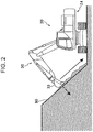
FIG. 2 is a side view illustrating the work machine in operation. -
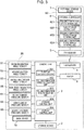
FIG. 3 is a circuit diagram of a compaction management system. -
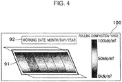
FIG. 4 is a diagram illustrating a rolling compaction record management screen displayed on a display. -
FIG. 5 is a diagram illustrating a rolling compaction state management screen displayed on the display. - Hereinafter, preferred embodiment of the present invention will be described with reference to the drawings.
- A compaction management system according to an embodiment of the present invention manages a compaction state of a compaction target ground. The compaction management system includes a work machine.
- As illustrated in
FIG. 1 which is a side view of awork machine 20, thework machine 20 is a machine, such as a hydraulic excavator, that performs work using anattachment 30. Thework machine 20 includes amachine body 24 having alower travelling body 21 and anupper slewing body 22, theattachment 30, and acylinder 40. - The
lower travelling body 21 is a portion that causes thework machine 20 to travel, and includes, for example, crawlers. Theupper slewing body 22 is rotatably attached to an upper portion of thelower travelling body 21 via a slewing device. A cab (operator's cab) 23 is provided in a front portion of theupper slewing body 22. - The attachment (work device) 30 is attached to the
upper slewing body 22 rotatably and vertically. Theattachment 30 includes aboom 31, anarm 32, and abucket 33. Theboom 31 is rotatably (raisably) attached to theupper slewing body 22. Thearm 32 is rotatably attached to theboom 31. Thebucket 33 is rotatably attached to thearm 32. Thebucket 33 performs work such as excavation, leveling, and scooping of a work target (earth and sand). - The cylinder (rotary device) 40 can hydraulically rotate the
attachment 30. Thecylinder 40 is a hydraulic telescopic cylinder. Thecylinder 40 includes aboom cylinder 41, anarm cylinder 42, and abucket cylinder 43. - The
boom cylinder 41 rotationally drives theboom 31 with respect to theupper slewing body 22. A proximal end of theboom cylinder 41 is rotatably attached to theupper slewing body 22. A distal end of theboom cylinder 41 is rotatably attached to theboom 31. - The
arm cylinder 42 rotationally drives thearm 32 with respect to theboom 31. A proximal end of thearm cylinder 42 is rotatably attached to theboom 31. A distal end of thearm cylinder 42 is rotatably attached to thearm 32. - The
bucket cylinder 43 rotationally drives thebucket 33 with respect to thearm 32. A proximal end of thebucket cylinder 43 is rotatably attached to thearm 32. A distal end of thebucket cylinder 43 is rotatably attached to alink member 34 rotatably attached to thebucket 33. - The
work machine 20 further includes aninclination angle sensor 50, a main bodyinclination angle sensor 55, apressure sensor 60, and a global navigation satellite system (GNSS)device 70. - The inclination angle sensor (work device attitude detection device) 50 detects an attitude of the
attachment 30. Theinclination angle sensor 50 includes a boominclination angle sensor 51, an arminclination angle sensor 52, and a bucketinclination angle sensor 53. - The boom
inclination angle sensor 51 is attached to theboom 31 and detects an attitude of theboom 31. The boominclination angle sensor 51 is, for example, an inclination (acceleration) sensor that acquires an inclination angle of theboom 31 with respect to a horizontal line. Note that the boominclination angle sensor 51 may be a rotation angle sensor that detects a rotation angle of a boom foot pin (boom proximal end) or a stroke sensor that detects a stroke amount of theboom cylinder 41. The horizontal line is, for example, parallel to a ground. - The arm
inclination angle sensor 52 is attached to thearm 32 and detects an attitude of thearm 32. The arminclination angle sensor 52 is, for example, an inclination (acceleration) sensor that acquires an inclination angle of thearm 32 with respect to the horizontal line. Note that the arminclination angle sensor 52 may be a rotation angle sensor that detects a rotation angle of an arm connecting pin (arm proximal end) or a stroke sensor that detects a stroke amount of thearm cylinder 42. - The bucket
inclination angle sensor 53 is attached to thelink member 34 and detects an attitude of thebucket 33. The bucketinclination angle sensor 53 is, for example, an inclination (acceleration) sensor that acquires an inclination angle of thebucket 33 with respect to the horizontal line. The bucketinclination angle sensor 53 may be a rotation angle sensor that detects a rotation angle of a bucket connecting pin (bucket proximal end) or a stroke sensor that detects a stroke amount of thebucket cylinder 43. - The main body inclination angle sensor (machine body attitude detection device) 55 is attached to the
upper slewing body 22 and detects an attitude of themachine body 24. The main bodyinclination angle sensor 55 is, for example, a biaxial inclination (acceleration) sensor that acquires an inclination angle of themachine body 24 with respect to a horizontal plane. - The pressure sensor (pressure detection device) 60 detects a pressure of the
cylinder 40. Thepressure sensor 60 includes a boomcylinder pressure sensor 61, an armcylinder pressure sensor 62, and a bucketcylinder pressure sensor 63. - The boom
cylinder pressure sensor 61 is attached to theboom cylinder 41 and detects a pressure on a head side and a pressure on a rod side of theboom cylinder 41. The armcylinder pressure sensor 62 is attached to thearm cylinder 42 and detects a pressure on a head side and a pressure on a rod side of thearm cylinder 42. The bucketcylinder pressure sensor 63 is attached to thebucket cylinder 43 and detects a pressure on a head side and a pressure on a rod side of thebucket cylinder 43. - At least two GNSS devices (position detection device and orientation detection device) 70 are disposed in the
machine body 24. TheGNSS devices 70 are attached to theupper slewing body 22 to be separated from each other. Theindividual GNSS device 70 receives a signal transmitted from a global positioning satellite system (GNSS). TheGNSS devices 70 each detect a time at which a signal is transmitted, based on the received signal, and detects the position of themachine body 24 using a radio wave speed and a radio wave transmission time (a difference between the transmission time and an arrival time). In addition, theGNSS devices 70 each detect an orientation of theupper slewing body 22, i.e. an orientation of theattachment 30 based on a deviation of the signals received by theindividual GNSS devices 70. -
FIG. 2 is a side view illustrating thework machine 20 in operation. As illustrated inFIG. 2 , thework machine 20 performs work of leveling acompaction target ground 90 with thebucket 33. In addition, thework machine 20 performs work of compacting thecompaction target ground 90. During the work of compacting thecompaction target ground 90, a bottom surface of thebucket 33 is pressed against thecompaction target ground 90. As a result, a rolling compaction force is applied to the place of thecompaction target ground 90 where thebucket 33 is pressed. -
FIG. 3 is a circuit diagram of the compaction management system 1. As illustrated inFIG. 3 , the compaction management system 1 includes astorage device 2, acontroller 3, and atransceiver 4. Thestorage device 2, thecontroller 3, and thetransceiver 4 are disposed in thework machine 20. - The storage device (dimension storage device) 2 stores dimensions of the
attachment 30. Thecontroller 3 includes aposition calculation unit 301, a rolling compactionforce calculation unit 302, a rolling compactionrecord creation unit 303, astorage control unit 304, and adisplay control unit 305. Theposition calculation unit 301 calculates, when thebucket 33 is pressed against the compaction target ground, a position of thebucket 33 using the attitude of themachine body 24 detected by the main bodyinclination angle sensor 55, the attitude of theattachment 30 detected by theinclination angle sensor 50, and a position and orientation of themachine body 24 detected by theindividual GNSS devices 70. An example of the position of thebucket 33 is three-dimensional coordinate data indicating latitude, longitude, and height at the central position of the bottom surface of thebucket 33. The position of thebucket 33 is an example of a rolling compaction position which is a pressing position of the work device against the compaction target position. - When the
bucket 33 is pressed against the compaction target ground, the rolling compactionforce calculation unit 302 calculates a rolling compaction force applied to thecompaction target ground 90 using the attitude of themachine body 24 detected by the main bodyinclination angle sensor 55, the attitude of theattachment 30 detected by theinclination angle sensor 50, the pressure detected by thepressure sensor 60, and the dimensions of theattachment 30 stored in thestorage device 2. - The rolling compaction force F (kN/m2) is calculated by dividing a calculation value (kN) of a pressing force, applied in a normal direction of the bottom surface of the
bucket 33, by an area (m2) of the bottom surface of thebucket 33. - The calculation value of the pressing force is calculated as follows. The rolling compaction
force calculation unit 302 adds a moment Fct of the weight of theattachment 30 generated around the boom foot and a moment Met calculated from cylinder thrust to calculate the calculation value of the pressing force. The moment Fct is calculated using the inclination angle of theboom 31 detected by the boominclination angle sensor 51, the inclination angle of thearm 32 detected by the arminclination angle sensor 52, the inclination angle of thebucket 33 detected by the bucketinclination angle sensor 53, and the inclination angle of themachine body 24 detected by the main bodyinclination angle sensor 55. - The moment Met is calculated as follows. The rolling compaction
force calculation unit 302 calculates the cylinder thrust of each of theboom cylinder 41, thearm cylinder 42, and thebucket cylinder 43 using the pressure on the head side and the pressure on the rod side detected by each of the boomcylinder pressure sensor 61, the armcylinder pressure sensor 62, and the bucketcylinder pressure sensor 63. Then, the rolling compactionforce calculation unit 302 calculates the moment Met using the calculated cylinder thrust. - The rolling compaction
force calculation unit 302 may sequentially calculate the above-described calculation value of the pressing force during the operation of thework machine 20. In this case, when the calculation value of the pressing force exceeds a predetermined threshold, theposition calculation unit 301 and the rolling compactionforce calculation unit 302 may determine that thebucket 33 is pressed against thecompaction target ground 90. - The GNSS device (time detection device) 70 detects a time when the
bucket 33 is pressed against thecompaction target ground 90. The rolling compactionrecord creation unit 303 creates a rolling compaction record in which the position of thebucket 33 calculated by itself, the rolling compaction force calculated by itself, and the time detected by theGNSS device 70 are associated with each other. - The
transceiver 4 includes a communication circuit capable of transmitting and receiving information to and from the outside of thework machine 20. - Further, the compaction management system 1 includes an
external management device 80. Theexternal management device 80 is disposed outside thework machine 20. Theexternal management device 80 is a server or a server group on a cloud. Theexternal management device 80 includes atransceiver 5, anexternal controller 6, and anexternal storage device 7. Thetransceiver 5 includes a communication circuit capable of externally transmitting and receiving information. - The
storage control unit 304 of thecontroller 3 causes thestorage device 2 to store the rolling compaction record created by itself. Storing the rolling compaction record in thestorage device 2 enables quantitative management of the rolling compaction force applied to a compacted portion of thecompaction target ground 90. Therefore, the compaction state of thecompaction target ground 90 can be accurately managed. - The rolling compaction record stored in the
storage device 2 includes the time when thebucket 33 is pressed against thecompaction target ground 90. Therefore, the time enables easy ascertainment of work efficiency. - The compaction management system 1 includes a display (display device) 8. The display 8 is disposed in the
cab 23 of thework machine 20. - The
display control unit 305 causes the display 8 to display the rolling compaction record created by itself. As a result, the operator who operates thework machine 20 can ascertain the compaction state of thecompaction target ground 90. -
FIG. 4 is a diagram illustrating a rolling compactionrecord management screen 100 displayed on the display 8. The rolling compactionrecord management screen 100 shows aground image 91 simulating thecompaction target ground 90. A surface of theground image 91 is color-coded according to the applied rolling compaction force. Thus, the distribution of the rolling compaction force can be seen at a glance. In addition, the rolling compactionrecord management screen 100 shows aninformation image 92 including information on execution date of work and the like. - Note that the rolling compaction
record management screen 100 is not limited to that illustrated inFIG. 4 . For example, the rolling compactionrecord management screen 100 may show position data of thebucket 33 and a numerical value of the rolling compaction force applied to the position in a text format. - Returning to
FIG. 3 , the external storage device (target value storage device) 7 of theexternal management device 80 stores target values of the rolling compaction forces at a plurality of locations on thecompaction target ground 90. Thecontroller 3 causes thetransceiver 4 to transmit the rolling compaction record stored in thestorage device 2 to theexternal management device 80. - The
external controller 6 includes a rolling compactionstate deriving unit 601, a targetvalue setting unit 602, a rolling compaction statestorage control unit 603, and a rolling compaction statedisplay control unit 604. - The rolling compaction
state deriving unit 601 derives a rolling compaction state in a specific position of thecompaction target ground 90 using the target values stored in theexternal storage device 7 and the rolling compaction record received from thework machine 20. Here, the rolling compaction state is a state of whether the rolling compaction force has been applied. This rolling compaction state enables a determination of whether the rolling compaction force has been applied to the specific position of thecompaction target ground 90. - Alternatively, the rolling compaction state is a state of whether the applied rolling compaction force has reached the target value. This rolling compaction state enables a determination of whether the applied rolling compaction force is sufficient at the specific position of the
compaction target ground 90. - Here, the target values of the rolling compaction forces stored in the
external storage device 7 are different from each other depending on positions on thecompaction target ground 90. For example, even when the target values are different between a peripheral portion and a central portion of thecompaction target ground 90, the rolling compaction state at each position on thecompaction target ground 90 can be ascertained. - The target
value setting unit 602 sets target values based on a shape of thecompaction target ground 90. For example, in the case where thecompaction target ground 90 easily loses its shape, the targetvalue setting unit 602 sets the target values to reflect the loss of shape in this value. As a result, the rolling compaction state can be derived based on the shape of thecompaction target ground 90. - The rolling compaction state
storage control unit 603 causes the external storage device (rolling compaction state storage device) 7 to store the rolling compaction state derived by itself. This enables the management of the rolling compaction state. - The rolling compaction state
display control unit 604 causes the display (rolling compaction state display device) 8 to display the rolling compaction state derived by itself. Specifically, theexternal controller 6 causes thetransceiver 5 to transmit the rolling compaction state to thework machine 20, and thecontroller 3 of thework machine 20 causes the display 8 to display the rolling compaction state. As a result, the operator operating thework machine 20 can ascertain the rolling compaction state. -
FIG. 5 is a diagram illustrating a rolling compactionstate management screen 200 displayed on the display 8. The rolling compactionstate management screen 200 shows, similarly to the rolling compactionrecord management screen 100, aground image 91 simulating thecompaction target ground 90. The surface of theground image 91 is color-coded according to the state of whether the rolling compaction force has been applied. Specifically, anunworked region 93 to which the rolling compaction force has not been applied and a workedregion 94 to which the rolling compaction force has been applied are color-coded. In addition, the workedregion 94 is color-coded according to the state of whether the rolling compaction force has reached the target value. Specifically, aninsufficient region 95 where the rolling compaction force has not reached the target value and anachievement region 96 where the rolling compaction force has reached the target value and the work has been completed are color-coded. As a result, the operator operating thework machine 20 can ascertain the rolling compaction state. - Note that the present invention is not limited to the configuration in which the
controller 3 of thework machine 20 calculates the position of thebucket 33 and the rolling compaction force applied to thecompaction target ground 90 when thebucket 33 is pressed against thecompaction target ground 90, and theexternal controller 6 of theexternal management device 80 may calculate them. Specifically, thecontroller 3 causes thetransceiver 4 to transmit the attitude of themachine body 24 detected by the main bodyinclination angle sensor 55, the attitude of theattachment 30 detected by theinclination angle sensor 50, and the position and orientation of themachine body 24 detected by theGNSS devices 70 to theexternal management device 80, and theexternal controller 6 calculates the position of thebucket 33 using them. In addition, thecontroller 3 causes thetransceiver 4 to transmit the attitude of themachine body 24 detected by the main bodyinclination angle sensor 55, the attitude of theattachment 30 detected by theinclination angle sensor 50, the pressure detected by thepressure sensor 60, and the dimensions of theattachment 30 stored in thestorage device 2 to theexternal management device 80, and theexternal controller 6 calculates the rolling compaction force applied to thecompaction target ground 90 using them. - In addition, the present invention is not limited to the configuration in which the
controller 3 of thework machine 20 creates the rolling compaction record, and theexternal controller 6 of theexternal management device 80 may create the rolling compaction record. Specifically, thecontroller 3 causes thetransceiver 4 to transmit the calculated position of thebucket 33, the time when thebucket 33 is pressed against thecompaction target ground 90, and the calculated rolling compaction force to theexternal management device 80, and theexternal controller 6 creates the rolling compaction record in which they are associated with each other. In this case, theexternal controller 6 may cause theexternal storage device 7 to store the created rolling compaction record. As a result, the rolling compaction record can be managed independently of thework machine 20. Therefore, the compaction state of thecompaction target ground 90 can be managed externally and centrally. - In addition, although the display 8 displays each of the rolling compaction
record management screen 100 and the rolling compactionstate management screen 200 in this configuration, a display device may display the rolling compactionrecord management screen 100 and a different display device (rolling compaction state display device) may display the rolling compactionstate management screen 200. In addition, although the display 8 is disposed in thework machine 20 in this configuration, it may be disposed in theexternal management device 80. - As described above, the compaction management system 1 according to the present embodiment causes the creation of the rolling compaction record in which the position of the
bucket 33 pressed against thecompaction target ground 90 is associated with the rolling compaction force applied to thecompaction target ground 90. Then, the rolling compaction record is stored in thestorage device 2. This enables quantitative management of the rolling compaction force applied to the compacted portion of thecompaction target ground 90. Therefore, the compaction state of the compaction target ground can be accurately managed. - In addition, the rolling compaction record stored in the
storage device 2 includes the time when thebucket 33 is pressed against thecompaction target ground 90. Therefore, the time enables easy ascertainment of work efficiency. - Further, when the rolling compaction record is stored in the
external storage device 7, the rolling compaction record can be managed independently of thework machine 20. Therefore, the compaction state of thecompaction target ground 90 can be managed externally and centrally. - In addition, the display 8 displays the rolling compaction record. This enables ascertainment of the compaction state of the
compaction target ground 90. - In addition, a rolling compaction state at a specific position of the
compaction target ground 90 is derived using the target values of the rolling compaction force and the rolling compaction record. This rolling compaction state enables the determination of whether the rolling compaction force has been applied and the rolling compaction force is sufficient at the specific position of thecompaction target ground 90. - In addition, the rolling compaction state is the state of whether the rolling compaction force has been applied. This rolling compaction state enables the determination of whether the rolling compaction force has been applied to the specific position of the
compaction target ground 90. - Further, the rolling compaction state is a state of whether the rolling compaction force has reached the target value. This rolling compaction state enables the determination of whether the applied rolling compaction force is sufficient at the specific position of the
compaction target ground 90. - In addition, the target value of the rolling compaction force varies with a position in the
compaction target ground 90. For example, even when the target values are different between the peripheral portion and the central portion of thecompaction target ground 90, the rolling compaction state at each portion of thecompaction target ground 90 can be ascertained. - In addition, the target value is set based on the shape of the
compaction target ground 90. For example, in the case where thecompaction target ground 90 easily loses its shape, the target value is set to reflect the loss of shape. As a result, the rolling compaction state can be derived based on the shape of thecompaction target ground 90. - Further, the derived rolling compaction state is stored in the
external storage device 7. This enables the management of the rolling compaction state. - Further, the derived rolling compaction state is displayed on the display 8. This enables the ascertainment of the rolling compaction state.
- Although the embodiment of the present invention has been described above, it is merely an example. The present invention is not particularly limited to the embodiment, and the specific configuration and the like can be modified in design as appropriate. In addition, the actions and effects described in the embodiment of the present invention are merely the most suitable actions and effects resulting from the present invention, and the actions and effects of the present invention are not limited to those described in the embodiment of the present invention.
- The technical features of the present embodiment are summarized as follows.
- A compaction management system according to an aspect of the present invention includes: a work machine including; a machine body, a work device attached to the machine body rotatably and vertically, a rotary device capable of hydraulically rotating the work device, a machine body attitude detection device that detects an attitude of the machine body, a work device attitude detection device that detects an attitude of the work device, a position detection device that detects a position of the machine body, an orientation detection device that detects an orientation of the machine body, a pressure detection device that detects a pressure of the rotary device, and a dimension storage device that stores dimensions of the work device; a position calculation unit that, when the work device is pressed against a compaction target ground, calculates a rolling compaction position which is a pressing position of the work device against the compaction target ground using the attitude of the machine body detected by the machine body attitude detection device, the attitude of the work device detected by the work device attitude detection device, the position of the machine body detected by the position detection device, and the orientation of the machine body detected by the orientation detection device; a rolling compaction force calculation unit that, when the work device is pressed against the compaction target ground, calculates a rolling compaction force applied to the compaction target ground using the attitude of the machine body detected by the machine body attitude detection device, the attitude of the work device detected by the work device attitude detection device, the pressure detected by the pressure detection device, and the dimensions of the work device stored in the dimension storage device; a rolling compaction record creation unit that creates a rolling compaction record in which the rolling compaction position is associated with the rolling compaction force calculated by the rolling compaction force calculation unit; a storage device; and a storage control unit that causes the storage device to store the rolling compaction record created by the rolling compaction record creation unit.
- This configuration causes the creation of the rolling compaction record in which the rolling compaction position calculated when the work device is pressed against the compaction target ground is associated with the rolling compaction force applied to the compaction target ground. Then, the rolling compaction record is stored in the storage device. This enables quantitative management of the rolling compaction force applied to the compacted portion of the compaction target ground. Therefore, the compaction state of the compaction target ground can be accurately managed.
- In the compaction management system, preferably, the work machine further includes a time detection device that detects a time when the work device is pressed against the compaction target ground, and the rolling compaction record creation unit creates the rolling compaction record in which the rolling compaction position, the rolling compaction force calculated by the rolling compaction force calculation unit, and the time detected by the time detection device are associated with each other.
- According to this configuration, the rolling compaction record stored in the storage device includes the time when the work device is pressed against the compaction target ground. Therefore, the time enables easy ascertainment of work efficiency.
- In the compaction management system, the storage device is preferably disposed outside the work machine.
- According to this configuration, the rolling compaction record is provided outside the work machine, and thus the rolling compaction record can be managed independently of the work machine. Therefore, the compaction state of the compaction target ground can be managed externally and centrally.
- The compaction management system preferably further includes a display device, and a display control unit that causes the display device to display the rolling compaction record created by the rolling compaction record creation unit.
- According to this configuration, the rolling compaction record is displayed on the display device. This enables the ascertainment of the compaction state of the compaction target ground.
- The compaction management system preferably further includes a target value storage device that stores target values of a rolling compaction force at a plurality of locations of the compaction target ground, and a rolling compaction state deriving unit that derives a rolling compaction state at a specific position of the compaction target ground using the target values stored in the target value storage device and the rolling compaction record stored in the storage device.
- According to this configuration, the rolling compaction state at the specific position of the compaction target ground is derived using the target values of the rolling compaction force and the rolling compaction record. This rolling compaction state enables the determination of whether the rolling compaction force has been applied and the rolling compaction force is sufficient at the specific position on the compaction target ground.
- In the compaction management system, the rolling compaction state is preferably a state of whether the rolling compaction force has been applied.
- According to this configuration, the rolling compaction state is the state of whether the rolling compaction force has been applied. This rolling compaction state enables the determination of whether the rolling compaction force has been applied to the specific position of the compaction target ground.
- In the compaction management system, the rolling compaction state is preferably a state of whether the rolling compaction force has reached the target value.
- According to this configuration, the rolling compaction state is the state of whether the rolling compaction force has reached the target value. This rolling compaction state enables the determination of whether the applied rolling compaction force is sufficient at the specific position of the compaction target ground.
- In the compaction management system, the target value preferably varies with a position in the compaction target ground.
- According to this configuration, the target value of the rolling compaction force varies with a position in the compaction target ground. For example, even when the target values are different between the peripheral portion and the central portion of the compaction target ground, the rolling compaction state at each position in the compaction target ground can be ascertained.
- The compaction management system preferably further includes a target value setting unit that sets the target values based on the shape of the compaction target ground.
- According to this configuration, the target value can be set base on the shape of the compaction target ground. For example, in the case where the compaction target ground easily loses its shape, the target value is set to reflect the loss of shape. This enables the deriving of the rolling compaction state based on the shape of the compaction target ground.
- The compaction management system preferably further includes a rolling compaction state storage device capable of storing the rolling compaction state, and a rolling compaction state storage control unit that causes the rolling compaction state storage device to store the rolling compaction state derived by the rolling compaction state deriving unit.
- This configuration causes the rolling compaction state storage device to store the derived rolling compaction state. This enables the management of the rolling compaction state.
- The compaction management system preferably further includes a rolling compaction state display device capable of displaying the rolling compaction state, and a rolling compaction state display control unit that causes the rolling compaction state display device to display the rolling compaction state derived by the rolling compaction state deriving unit.
- This configuration causes the rolling compaction state display device to display the derived rolling compaction state. This enables the ascertainment of the rolling compaction state.
Claims (11)
- A compaction management system, comprising:a work machine including;a machine body,a work device attached to the machine body rotatably and vertically,a rotary device capable of hydraulically rotating the work device,a machine body attitude detection device that detects an attitude of the machine body,a work device attitude detection device that detects an attitude of the work device,a position detection device that detects a position of the machine body,an orientation detection device that detects an orientation of the machine body,a pressure detection device that detects a pressure of the rotary device, anda dimension storage device that stores dimensions of the work device;a position calculation unit that, when the work device is pressed against a compaction target ground, calculates a rolling compaction position which is a pressing position of the work device against the compaction target ground using the attitude of the machine body detected by the machine body attitude detection device, the attitude of the work device detected by the work device attitude detection device, the position of the machine body detected by the position detection device, and the orientation of the machine body detected by the orientation detection device;a rolling compaction force calculation unit that, when the work device is pressed against the compaction target ground, calculates a rolling compaction force applied to the compaction target ground using the attitude of the machine body detected by the machine body attitude detection device, the attitude of the work device detected by the work device attitude detection device, the pressure detected by the pressure detection device, and the dimensions of the work device stored in the dimension storage device;a rolling compaction record creation unit that creates a rolling compaction record in which the rolling compaction position is associated with the rolling compaction force calculated by the rolling compaction force calculation unit;a storage device; anda storage control unit that causes the storage device to store the rolling compaction record created by the rolling compaction record creation unit.
- The compaction management system according to claim 1, whereinthe work machine further includes a time detection device that detects a time when the work device is pressed against the compaction target ground, andthe rolling compaction record creation unit creates the rolling compaction record in which the rolling compaction position, the rolling compaction force calculated by the rolling compaction force calculation unit, and the time detected by the time detection device are associated with each other.
- The compaction management system according to claim 1 or 2, wherein the storage device is disposed outside the work machine.
- The compaction management system according to any one of claims 1 to 3, further comprising:a display device; anda display control unit that causes the display device to display the rolling compaction record created by the rolling compaction record creation unit.
- The compaction management system according to any one of claims 1 to 4, further comprising:a target value storage device that stores target values of a rolling compaction force at a plurality of locations of the compaction target ground; anda rolling compaction state deriving unit that derives a rolling compaction state at a specific position of the compaction target ground using the target values stored in the target value storage device and the rolling compaction record stored in the storage device.
- The compaction management system according to claim 5, wherein the rolling compaction state is a state of whether the rolling compaction force has been applied.
- The compaction management system according to claim 5, wherein the rolling compaction state is a state of whether the rolling compaction force has reached the target value.
- The compaction management system according to any one of claims 5 to 7, wherein the target value varies with a position on the compaction target ground.
- The compaction management system according to any one of claims 5 to 8, further comprising a target value setting unit that sets the target values based on a shape of the compaction target ground.
- The compaction management system according to any one of claims 5 to 9, further comprising:a rolling compaction state storage device capable of storing the rolling compaction state; anda rolling compaction state storage control unit that causes the rolling compaction state storage device to store the rolling compaction state derived by the rolling compaction state deriving unit.
- The compaction management system according to any one of claims 5 to 10, further comprising:a rolling compaction state display device capable of displaying the rolling compaction state; anda rolling compaction state display control unit that causes the rolling compaction state display device to display the rolling compaction state derived by the rolling compaction state deriving unit.
Applications Claiming Priority (2)
| Application Number | Priority Date | Filing Date | Title |
|---|---|---|---|
| JP2019050739A JP7135956B2 (en) | 2019-03-19 | 2019-03-19 | Compaction management system |
| PCT/JP2020/010796 WO2020189494A1 (en) | 2019-03-19 | 2020-03-12 | Compaction management system |
Publications (3)
| Publication Number | Publication Date |
|---|---|
| EP3913147A1 true EP3913147A1 (en) | 2021-11-24 |
| EP3913147A4 EP3913147A4 (en) | 2022-05-11 |
| EP3913147B1 EP3913147B1 (en) | 2024-07-17 |
Family
ID=72519409
Family Applications (1)
| Application Number | Title | Priority Date | Filing Date |
|---|---|---|---|
| EP20773053.2A Active EP3913147B1 (en) | 2019-03-19 | 2020-03-12 | Compaction management system |
Country Status (5)
| Country | Link |
|---|---|
| US (1) | US12104352B2 (en) |
| EP (1) | EP3913147B1 (en) |
| JP (1) | JP7135956B2 (en) |
| CN (1) | CN113396259B (en) |
| WO (1) | WO2020189494A1 (en) |
Families Citing this family (8)
| Publication number | Priority date | Publication date | Assignee | Title |
|---|---|---|---|---|
| JP7424960B2 (en) * | 2020-11-17 | 2024-01-30 | 株式会社小松製作所 | Information acquisition system and information acquisition method |
| JP7794689B2 (en) * | 2022-05-13 | 2026-01-06 | 鹿島建設株式会社 | Soil management device and soil management method |
| US12410574B2 (en) | 2022-08-22 | 2025-09-09 | Deere & Company | Ground compaction sensing system and method for a work machine |
| CN115374826B (en) * | 2022-08-29 | 2023-04-25 | 中国铁道科学研究院集团有限公司铁道建筑研究所 | Machine soil direct contact type packing compaction state judging method and application |
| JP2024049143A (en) * | 2022-09-28 | 2024-04-09 | 日立建機株式会社 | Access Area Management System |
| KR102635327B1 (en) * | 2022-11-25 | 2024-02-07 | 건설기계부품연구원 | Compaction device and compaction quality managing system comprising it |
| US12473709B2 (en) * | 2023-03-09 | 2025-11-18 | Kubota Corporation | Working machine |
| JP7698825B1 (en) | 2024-03-18 | 2025-06-26 | 株式会社アクティブ・ソリューション | Compaction control unit and compaction control system |
Family Cites Families (14)
| Publication number | Priority date | Publication date | Assignee | Title |
|---|---|---|---|---|
| JP3258891B2 (en) * | 1996-02-21 | 2002-02-18 | 新キャタピラー三菱株式会社 | Work machine control method and device for construction machine |
| KR100231757B1 (en) | 1996-02-21 | 1999-11-15 | 사쿠마 하지메 | Method and device for controlling attachment of construction machine |
| JP2000265413A (en) * | 1999-03-12 | 2000-09-26 | Heat Parts:Kk | Rolling compaction device and rolling compaction method |
| JP3460224B2 (en) | 1999-06-09 | 2003-10-27 | 株式会社大林組 | Embankment compaction management system |
| JP2002021122A (en) * | 2000-07-10 | 2002-01-23 | Hitachi Constr Mach Co Ltd | Load measuring device for back hoe |
| JP2010084383A (en) * | 2008-09-30 | 2010-04-15 | Naomasa Nitta | Rolling compaction bucket |
| JP5342900B2 (en) * | 2009-03-06 | 2013-11-13 | 株式会社小松製作所 | Construction machine, construction machine control method, and program for causing computer to execute the method |
| JP5512438B2 (en) * | 2010-07-21 | 2014-06-04 | 大成建設株式会社 | Law shoulder tightness management device |
| JP5499069B2 (en) * | 2012-03-30 | 2014-05-21 | 株式会社淺川組 | Slope compaction device |
| JP5597222B2 (en) * | 2012-04-11 | 2014-10-01 | 株式会社小松製作所 | Excavator drilling control system |
| US9423332B2 (en) * | 2014-10-14 | 2016-08-23 | Caterpillar Inc. | System and method for validating compaction of a work site |
| CN105971051B (en) * | 2015-03-12 | 2021-04-30 | 住友重机械工业株式会社 | Digging machine |
| KR101862735B1 (en) * | 2016-03-29 | 2018-07-04 | 가부시키가이샤 고마쓰 세이사쿠쇼 | Work equipment control device, work equipment, and work equipment control method |
| GB2558250B (en) * | 2016-12-23 | 2020-05-27 | Caterpillar Sarl | A method of determining the compaction of a terrain of a worksite |
-
2019
- 2019-03-19 JP JP2019050739A patent/JP7135956B2/en active Active
-
2020
- 2020-03-12 WO PCT/JP2020/010796 patent/WO2020189494A1/en not_active Ceased
- 2020-03-12 EP EP20773053.2A patent/EP3913147B1/en active Active
- 2020-03-12 CN CN202080014201.0A patent/CN113396259B/en active Active
- 2020-03-12 US US17/435,231 patent/US12104352B2/en active Active
Also Published As
| Publication number | Publication date |
|---|---|
| JP2020153099A (en) | 2020-09-24 |
| US12104352B2 (en) | 2024-10-01 |
| CN113396259B (en) | 2022-07-19 |
| JP7135956B2 (en) | 2022-09-13 |
| EP3913147A4 (en) | 2022-05-11 |
| WO2020189494A1 (en) | 2020-09-24 |
| EP3913147B1 (en) | 2024-07-17 |
| US20220145584A1 (en) | 2022-05-12 |
| CN113396259A (en) | 2021-09-14 |
Similar Documents
| Publication | Publication Date | Title |
|---|---|---|
| EP3913147B1 (en) | Compaction management system | |
| AU2022209235B2 (en) | Display control device and display control method | |
| US11427984B2 (en) | Work machine | |
| US6711838B2 (en) | Method and apparatus for determining machine location | |
| KR102659153B1 (en) | Shovel, information processing device | |
| EP2912232B1 (en) | Wheel loader comprising a grading blade and a machine control system | |
| JP6782270B2 (en) | Construction management system and work machine | |
| AU2019292457B2 (en) | Display control device, display control system, and display control method | |
| EP3119660B1 (en) | System and method for positioning construction machine | |
| CN112074641B (en) | Control device and control method | |
| EP3426852B1 (en) | Measuring equipment for determining the result of earthmoving work | |
| CN115698433B (en) | Compaction Management System | |
| US20220389682A1 (en) | Overturning-risk presentation device and overturning-risk presentation method | |
| JP7371338B2 (en) | Ground strength measurement system | |
| US12116754B2 (en) | Operation area presentation device and operation area presentation method | |
| US20230291989A1 (en) | Display control device and display method | |
| US20220375157A1 (en) | Overturning-risk presentation device and overturning-risk presentation method | |
| WO2017061512A1 (en) | Work-performing method, control system for work machine, and work machine | |
| AU2021352215B2 (en) | Display control device and display control method | |
| JP2024104895A (en) | MEASURING DEVICE FOR CONSTRUCTION MACHINE, CONTROL DEVICE FOR CONSTRUCTION MACHINE, AND MANAGEMENT DEVICE FOR CONSTRUCTION MACHINE | |
| JP7739072B2 (en) | Work machinery | |
| US20250084617A1 (en) | System and method of work machine implement control for subterranean mapping applications | |
| JP2025075780A (en) | DISPLAY CONTROL DEVICE, DISPLAY CONTROL SYSTEM, AND DISPLAY CONTROL METHOD | |
| JP2024049143A (en) | Access Area Management System |
Legal Events
| Date | Code | Title | Description |
|---|---|---|---|
| STAA | Information on the status of an ep patent application or granted ep patent |
Free format text: STATUS: THE INTERNATIONAL PUBLICATION HAS BEEN MADE |
|
| PUAI | Public reference made under article 153(3) epc to a published international application that has entered the european phase |
Free format text: ORIGINAL CODE: 0009012 |
|
| STAA | Information on the status of an ep patent application or granted ep patent |
Free format text: STATUS: REQUEST FOR EXAMINATION WAS MADE |
|
| 17P | Request for examination filed |
Effective date: 20210816 |
|
| AK | Designated contracting states |
Kind code of ref document: A1 Designated state(s): AL AT BE BG CH CY CZ DE DK EE ES FI FR GB GR HR HU IE IS IT LI LT LU LV MC MK MT NL NO PL PT RO RS SE SI SK SM TR |
|
| A4 | Supplementary search report drawn up and despatched |
Effective date: 20220413 |
|
| RIC1 | Information provided on ipc code assigned before grant |
Ipc: E02F 9/26 20060101ALI20220407BHEP Ipc: E02F 3/96 20060101ALI20220407BHEP Ipc: E02F 3/43 20060101ALI20220407BHEP Ipc: E01C 19/28 20060101ALI20220407BHEP Ipc: E02F 9/20 20060101AFI20220407BHEP |
|
| DAV | Request for validation of the european patent (deleted) | ||
| DAX | Request for extension of the european patent (deleted) | ||
| GRAP | Despatch of communication of intention to grant a patent |
Free format text: ORIGINAL CODE: EPIDOSNIGR1 |
|
| STAA | Information on the status of an ep patent application or granted ep patent |
Free format text: STATUS: GRANT OF PATENT IS INTENDED |
|
| RIC1 | Information provided on ipc code assigned before grant |
Ipc: E02F 9/26 20060101ALI20240131BHEP Ipc: E02F 3/96 20060101ALI20240131BHEP Ipc: E02F 3/43 20060101ALI20240131BHEP Ipc: E01C 19/28 20060101ALI20240131BHEP Ipc: E02F 9/20 20060101AFI20240131BHEP |
|
| INTG | Intention to grant announced |
Effective date: 20240306 |
|
| GRAS | Grant fee paid |
Free format text: ORIGINAL CODE: EPIDOSNIGR3 |
|
| GRAA | (expected) grant |
Free format text: ORIGINAL CODE: 0009210 |
|
| STAA | Information on the status of an ep patent application or granted ep patent |
Free format text: STATUS: THE PATENT HAS BEEN GRANTED |
|
| AK | Designated contracting states |
Kind code of ref document: B1 Designated state(s): AL AT BE BG CH CY CZ DE DK EE ES FI FR GB GR HR HU IE IS IT LI LT LU LV MC MK MT NL NO PL PT RO RS SE SI SK SM TR |
|
| REG | Reference to a national code |
Ref country code: CH Ref legal event code: EP |
|
| REG | Reference to a national code |
Ref country code: DE Ref legal event code: R096 Ref document number: 602020034171 Country of ref document: DE |
|
| REG | Reference to a national code |
Ref country code: IE Ref legal event code: FG4D |
|
| REG | Reference to a national code |
Ref country code: LT Ref legal event code: MG9D |
|
| REG | Reference to a national code |
Ref country code: NL Ref legal event code: MP Effective date: 20240717 |
|
| PG25 | Lapsed in a contracting state [announced via postgrant information from national office to epo] |
Ref country code: PT Free format text: LAPSE BECAUSE OF FAILURE TO SUBMIT A TRANSLATION OF THE DESCRIPTION OR TO PAY THE FEE WITHIN THE PRESCRIBED TIME-LIMIT Effective date: 20241118 |
|
| REG | Reference to a national code |
Ref country code: AT Ref legal event code: MK05 Ref document number: 1704254 Country of ref document: AT Kind code of ref document: T Effective date: 20240717 |
|
| PG25 | Lapsed in a contracting state [announced via postgrant information from national office to epo] |
Ref country code: NL Free format text: LAPSE BECAUSE OF FAILURE TO SUBMIT A TRANSLATION OF THE DESCRIPTION OR TO PAY THE FEE WITHIN THE PRESCRIBED TIME-LIMIT Effective date: 20240717 |
|
| PG25 | Lapsed in a contracting state [announced via postgrant information from national office to epo] |
Ref country code: PT Free format text: LAPSE BECAUSE OF FAILURE TO SUBMIT A TRANSLATION OF THE DESCRIPTION OR TO PAY THE FEE WITHIN THE PRESCRIBED TIME-LIMIT Effective date: 20241118 Ref country code: NL Free format text: LAPSE BECAUSE OF FAILURE TO SUBMIT A TRANSLATION OF THE DESCRIPTION OR TO PAY THE FEE WITHIN THE PRESCRIBED TIME-LIMIT Effective date: 20240717 |
|
| PG25 | Lapsed in a contracting state [announced via postgrant information from national office to epo] |
Ref country code: NO Free format text: LAPSE BECAUSE OF FAILURE TO SUBMIT A TRANSLATION OF THE DESCRIPTION OR TO PAY THE FEE WITHIN THE PRESCRIBED TIME-LIMIT Effective date: 20241017 |
|
| PG25 | Lapsed in a contracting state [announced via postgrant information from national office to epo] |
Ref country code: GR Free format text: LAPSE BECAUSE OF FAILURE TO SUBMIT A TRANSLATION OF THE DESCRIPTION OR TO PAY THE FEE WITHIN THE PRESCRIBED TIME-LIMIT Effective date: 20241018 Ref country code: PL Free format text: LAPSE BECAUSE OF FAILURE TO SUBMIT A TRANSLATION OF THE DESCRIPTION OR TO PAY THE FEE WITHIN THE PRESCRIBED TIME-LIMIT Effective date: 20240717 Ref country code: FI Free format text: LAPSE BECAUSE OF FAILURE TO SUBMIT A TRANSLATION OF THE DESCRIPTION OR TO PAY THE FEE WITHIN THE PRESCRIBED TIME-LIMIT Effective date: 20240717 |
|
| PG25 | Lapsed in a contracting state [announced via postgrant information from national office to epo] |
Ref country code: BG Free format text: LAPSE BECAUSE OF FAILURE TO SUBMIT A TRANSLATION OF THE DESCRIPTION OR TO PAY THE FEE WITHIN THE PRESCRIBED TIME-LIMIT Effective date: 20240717 |
|
| PG25 | Lapsed in a contracting state [announced via postgrant information from national office to epo] |
Ref country code: LV Free format text: LAPSE BECAUSE OF FAILURE TO SUBMIT A TRANSLATION OF THE DESCRIPTION OR TO PAY THE FEE WITHIN THE PRESCRIBED TIME-LIMIT Effective date: 20240717 |
|
| PG25 | Lapsed in a contracting state [announced via postgrant information from national office to epo] |
Ref country code: IS Free format text: LAPSE BECAUSE OF FAILURE TO SUBMIT A TRANSLATION OF THE DESCRIPTION OR TO PAY THE FEE WITHIN THE PRESCRIBED TIME-LIMIT Effective date: 20241117 Ref country code: AT Free format text: LAPSE BECAUSE OF FAILURE TO SUBMIT A TRANSLATION OF THE DESCRIPTION OR TO PAY THE FEE WITHIN THE PRESCRIBED TIME-LIMIT Effective date: 20240717 |
|
| PG25 | Lapsed in a contracting state [announced via postgrant information from national office to epo] |
Ref country code: HR Free format text: LAPSE BECAUSE OF FAILURE TO SUBMIT A TRANSLATION OF THE DESCRIPTION OR TO PAY THE FEE WITHIN THE PRESCRIBED TIME-LIMIT Effective date: 20240717 |
|
| PG25 | Lapsed in a contracting state [announced via postgrant information from national office to epo] |
Ref country code: ES Free format text: LAPSE BECAUSE OF FAILURE TO SUBMIT A TRANSLATION OF THE DESCRIPTION OR TO PAY THE FEE WITHIN THE PRESCRIBED TIME-LIMIT Effective date: 20240717 Ref country code: RS Free format text: LAPSE BECAUSE OF FAILURE TO SUBMIT A TRANSLATION OF THE DESCRIPTION OR TO PAY THE FEE WITHIN THE PRESCRIBED TIME-LIMIT Effective date: 20241017 |
|
| PG25 | Lapsed in a contracting state [announced via postgrant information from national office to epo] |
Ref country code: RS Free format text: LAPSE BECAUSE OF FAILURE TO SUBMIT A TRANSLATION OF THE DESCRIPTION OR TO PAY THE FEE WITHIN THE PRESCRIBED TIME-LIMIT Effective date: 20241017 Ref country code: PL Free format text: LAPSE BECAUSE OF FAILURE TO SUBMIT A TRANSLATION OF THE DESCRIPTION OR TO PAY THE FEE WITHIN THE PRESCRIBED TIME-LIMIT Effective date: 20240717 Ref country code: NO Free format text: LAPSE BECAUSE OF FAILURE TO SUBMIT A TRANSLATION OF THE DESCRIPTION OR TO PAY THE FEE WITHIN THE PRESCRIBED TIME-LIMIT Effective date: 20241017 Ref country code: LV Free format text: LAPSE BECAUSE OF FAILURE TO SUBMIT A TRANSLATION OF THE DESCRIPTION OR TO PAY THE FEE WITHIN THE PRESCRIBED TIME-LIMIT Effective date: 20240717 Ref country code: IS Free format text: LAPSE BECAUSE OF FAILURE TO SUBMIT A TRANSLATION OF THE DESCRIPTION OR TO PAY THE FEE WITHIN THE PRESCRIBED TIME-LIMIT Effective date: 20241117 Ref country code: HR Free format text: LAPSE BECAUSE OF FAILURE TO SUBMIT A TRANSLATION OF THE DESCRIPTION OR TO PAY THE FEE WITHIN THE PRESCRIBED TIME-LIMIT Effective date: 20240717 Ref country code: GR Free format text: LAPSE BECAUSE OF FAILURE TO SUBMIT A TRANSLATION OF THE DESCRIPTION OR TO PAY THE FEE WITHIN THE PRESCRIBED TIME-LIMIT Effective date: 20241018 Ref country code: FI Free format text: LAPSE BECAUSE OF FAILURE TO SUBMIT A TRANSLATION OF THE DESCRIPTION OR TO PAY THE FEE WITHIN THE PRESCRIBED TIME-LIMIT Effective date: 20240717 Ref country code: ES Free format text: LAPSE BECAUSE OF FAILURE TO SUBMIT A TRANSLATION OF THE DESCRIPTION OR TO PAY THE FEE WITHIN THE PRESCRIBED TIME-LIMIT Effective date: 20240717 Ref country code: BG Free format text: LAPSE BECAUSE OF FAILURE TO SUBMIT A TRANSLATION OF THE DESCRIPTION OR TO PAY THE FEE WITHIN THE PRESCRIBED TIME-LIMIT Effective date: 20240717 Ref country code: AT Free format text: LAPSE BECAUSE OF FAILURE TO SUBMIT A TRANSLATION OF THE DESCRIPTION OR TO PAY THE FEE WITHIN THE PRESCRIBED TIME-LIMIT Effective date: 20240717 |
|
| PG25 | Lapsed in a contracting state [announced via postgrant information from national office to epo] |
Ref country code: DK Free format text: LAPSE BECAUSE OF FAILURE TO SUBMIT A TRANSLATION OF THE DESCRIPTION OR TO PAY THE FEE WITHIN THE PRESCRIBED TIME-LIMIT Effective date: 20240717 Ref country code: SM Free format text: LAPSE BECAUSE OF FAILURE TO SUBMIT A TRANSLATION OF THE DESCRIPTION OR TO PAY THE FEE WITHIN THE PRESCRIBED TIME-LIMIT Effective date: 20240717 Ref country code: RO Free format text: LAPSE BECAUSE OF FAILURE TO SUBMIT A TRANSLATION OF THE DESCRIPTION OR TO PAY THE FEE WITHIN THE PRESCRIBED TIME-LIMIT Effective date: 20240717 |
|
| REG | Reference to a national code |
Ref country code: DE Ref legal event code: R097 Ref document number: 602020034171 Country of ref document: DE |
|
| PG25 | Lapsed in a contracting state [announced via postgrant information from national office to epo] |
Ref country code: EE Free format text: LAPSE BECAUSE OF FAILURE TO SUBMIT A TRANSLATION OF THE DESCRIPTION OR TO PAY THE FEE WITHIN THE PRESCRIBED TIME-LIMIT Effective date: 20240717 |
|
| PG25 | Lapsed in a contracting state [announced via postgrant information from national office to epo] |
Ref country code: CZ Free format text: LAPSE BECAUSE OF FAILURE TO SUBMIT A TRANSLATION OF THE DESCRIPTION OR TO PAY THE FEE WITHIN THE PRESCRIBED TIME-LIMIT Effective date: 20240717 |
|
| PG25 | Lapsed in a contracting state [announced via postgrant information from national office to epo] |
Ref country code: SK Free format text: LAPSE BECAUSE OF FAILURE TO SUBMIT A TRANSLATION OF THE DESCRIPTION OR TO PAY THE FEE WITHIN THE PRESCRIBED TIME-LIMIT Effective date: 20240717 |
|
| PLBE | No opposition filed within time limit |
Free format text: ORIGINAL CODE: 0009261 |
|
| STAA | Information on the status of an ep patent application or granted ep patent |
Free format text: STATUS: NO OPPOSITION FILED WITHIN TIME LIMIT |
|
| 26N | No opposition filed |
Effective date: 20250422 |
|
| PG25 | Lapsed in a contracting state [announced via postgrant information from national office to epo] |
Ref country code: SE Free format text: LAPSE BECAUSE OF FAILURE TO SUBMIT A TRANSLATION OF THE DESCRIPTION OR TO PAY THE FEE WITHIN THE PRESCRIBED TIME-LIMIT Effective date: 20240717 |
|
| PG25 | Lapsed in a contracting state [announced via postgrant information from national office to epo] |
Ref country code: MC Free format text: LAPSE BECAUSE OF FAILURE TO SUBMIT A TRANSLATION OF THE DESCRIPTION OR TO PAY THE FEE WITHIN THE PRESCRIBED TIME-LIMIT Effective date: 20240717 |
|
| REG | Reference to a national code |
Ref country code: CH Ref legal event code: H13 Free format text: ST27 STATUS EVENT CODE: U-0-0-H10-H13 (AS PROVIDED BY THE NATIONAL OFFICE) Effective date: 20251024 |
|
| PG25 | Lapsed in a contracting state [announced via postgrant information from national office to epo] |
Ref country code: LU Free format text: LAPSE BECAUSE OF NON-PAYMENT OF DUE FEES Effective date: 20250312 |
|
| REG | Reference to a national code |
Ref country code: BE Ref legal event code: MM Effective date: 20250331 |
|
| PG25 | Lapsed in a contracting state [announced via postgrant information from national office to epo] |
Ref country code: BE Free format text: LAPSE BECAUSE OF NON-PAYMENT OF DUE FEES Effective date: 20250331 |
|
| PG25 | Lapsed in a contracting state [announced via postgrant information from national office to epo] |
Ref country code: CH Free format text: LAPSE BECAUSE OF NON-PAYMENT OF DUE FEES Effective date: 20250331 |
|
| PG25 | Lapsed in a contracting state [announced via postgrant information from national office to epo] |
Ref country code: IE Free format text: LAPSE BECAUSE OF NON-PAYMENT OF DUE FEES Effective date: 20250312 |
|
| PG25 | Lapsed in a contracting state [announced via postgrant information from national office to epo] |
Ref country code: IT Free format text: LAPSE BECAUSE OF FAILURE TO SUBMIT A TRANSLATION OF THE DESCRIPTION OR TO PAY THE FEE WITHIN THE PRESCRIBED TIME-LIMIT Effective date: 20240717 |
|
| PGFP | Annual fee paid to national office [announced via postgrant information from national office to epo] |
Ref country code: GB Payment date: 20260202 Year of fee payment: 7 |
|
| PGFP | Annual fee paid to national office [announced via postgrant information from national office to epo] |
Ref country code: DE Payment date: 20260128 Year of fee payment: 7 |
|
| PGFP | Annual fee paid to national office [announced via postgrant information from national office to epo] |
Ref country code: FR Payment date: 20260209 Year of fee payment: 7 |