EP3912945A1 - Filament winding device - Google Patents
Filament winding device Download PDFInfo
- Publication number
- EP3912945A1 EP3912945A1 EP19909736.1A EP19909736A EP3912945A1 EP 3912945 A1 EP3912945 A1 EP 3912945A1 EP 19909736 A EP19909736 A EP 19909736A EP 3912945 A1 EP3912945 A1 EP 3912945A1
- Authority
- EP
- European Patent Office
- Prior art keywords
- peel
- liner
- axial direction
- fiber bundle
- remaining yarn
- Prior art date
- Legal status (The legal status is an assumption and is not a legal conclusion. Google has not performed a legal analysis and makes no representation as to the accuracy of the status listed.)
- Granted
Links
Images









Classifications
-
- B—PERFORMING OPERATIONS; TRANSPORTING
- B29—WORKING OF PLASTICS; WORKING OF SUBSTANCES IN A PLASTIC STATE IN GENERAL
- B29C—SHAPING OR JOINING OF PLASTICS; SHAPING OF MATERIAL IN A PLASTIC STATE, NOT OTHERWISE PROVIDED FOR; AFTER-TREATMENT OF THE SHAPED PRODUCTS, e.g. REPAIRING
- B29C53/00—Shaping by bending, folding, twisting, straightening or flattening; Apparatus therefor
- B29C53/56—Winding and joining, e.g. winding spirally
- B29C53/58—Winding and joining, e.g. winding spirally helically
- B29C53/60—Winding and joining, e.g. winding spirally helically using internal forming surfaces, e.g. mandrels
- B29C53/602—Winding and joining, e.g. winding spirally helically using internal forming surfaces, e.g. mandrels for tubular articles having closed or nearly closed ends, e.g. vessels, tanks, containers
-
- B—PERFORMING OPERATIONS; TRANSPORTING
- B29—WORKING OF PLASTICS; WORKING OF SUBSTANCES IN A PLASTIC STATE IN GENERAL
- B29C—SHAPING OR JOINING OF PLASTICS; SHAPING OF MATERIAL IN A PLASTIC STATE, NOT OTHERWISE PROVIDED FOR; AFTER-TREATMENT OF THE SHAPED PRODUCTS, e.g. REPAIRING
- B29C70/00—Shaping composites, i.e. plastics material comprising reinforcements, fillers or preformed parts, e.g. inserts
- B29C70/04—Shaping composites, i.e. plastics material comprising reinforcements, fillers or preformed parts, e.g. inserts comprising reinforcements only, e.g. self-reinforcing plastics
- B29C70/28—Shaping operations therefor
- B29C70/30—Shaping by lay-up, i.e. applying fibres, tape or broadsheet on a mould, former or core; Shaping by spray-up, i.e. spraying of fibres on a mould, former or core
- B29C70/32—Shaping by lay-up, i.e. applying fibres, tape or broadsheet on a mould, former or core; Shaping by spray-up, i.e. spraying of fibres on a mould, former or core on a rotating mould, former or core
-
- B—PERFORMING OPERATIONS; TRANSPORTING
- B29—WORKING OF PLASTICS; WORKING OF SUBSTANCES IN A PLASTIC STATE IN GENERAL
- B29C—SHAPING OR JOINING OF PLASTICS; SHAPING OF MATERIAL IN A PLASTIC STATE, NOT OTHERWISE PROVIDED FOR; AFTER-TREATMENT OF THE SHAPED PRODUCTS, e.g. REPAIRING
- B29C53/00—Shaping by bending, folding, twisting, straightening or flattening; Apparatus therefor
- B29C53/56—Winding and joining, e.g. winding spirally
- B29C53/58—Winding and joining, e.g. winding spirally helically
-
- B—PERFORMING OPERATIONS; TRANSPORTING
- B29—WORKING OF PLASTICS; WORKING OF SUBSTANCES IN A PLASTIC STATE IN GENERAL
- B29C—SHAPING OR JOINING OF PLASTICS; SHAPING OF MATERIAL IN A PLASTIC STATE, NOT OTHERWISE PROVIDED FOR; AFTER-TREATMENT OF THE SHAPED PRODUCTS, e.g. REPAIRING
- B29C53/00—Shaping by bending, folding, twisting, straightening or flattening; Apparatus therefor
- B29C53/56—Winding and joining, e.g. winding spirally
- B29C53/58—Winding and joining, e.g. winding spirally helically
- B29C53/581—Winding and joining, e.g. winding spirally helically using sheets or strips consisting principally of plastics material
- B29C53/582—Winding and joining, e.g. winding spirally helically using sheets or strips consisting principally of plastics material comprising reinforcements, e.g. wires, threads
-
- B—PERFORMING OPERATIONS; TRANSPORTING
- B29—WORKING OF PLASTICS; WORKING OF SUBSTANCES IN A PLASTIC STATE IN GENERAL
- B29C—SHAPING OR JOINING OF PLASTICS; SHAPING OF MATERIAL IN A PLASTIC STATE, NOT OTHERWISE PROVIDED FOR; AFTER-TREATMENT OF THE SHAPED PRODUCTS, e.g. REPAIRING
- B29C53/00—Shaping by bending, folding, twisting, straightening or flattening; Apparatus therefor
- B29C53/56—Winding and joining, e.g. winding spirally
- B29C53/58—Winding and joining, e.g. winding spirally helically
- B29C53/60—Winding and joining, e.g. winding spirally helically using internal forming surfaces, e.g. mandrels
- B29C53/62—Winding and joining, e.g. winding spirally helically using internal forming surfaces, e.g. mandrels rotatable about the winding axis
- B29C53/64—Winding and joining, e.g. winding spirally helically using internal forming surfaces, e.g. mandrels rotatable about the winding axis and moving axially
-
- B—PERFORMING OPERATIONS; TRANSPORTING
- B29—WORKING OF PLASTICS; WORKING OF SUBSTANCES IN A PLASTIC STATE IN GENERAL
- B29C—SHAPING OR JOINING OF PLASTICS; SHAPING OF MATERIAL IN A PLASTIC STATE, NOT OTHERWISE PROVIDED FOR; AFTER-TREATMENT OF THE SHAPED PRODUCTS, e.g. REPAIRING
- B29C53/00—Shaping by bending, folding, twisting, straightening or flattening; Apparatus therefor
- B29C53/56—Winding and joining, e.g. winding spirally
- B29C53/58—Winding and joining, e.g. winding spirally helically
- B29C53/60—Winding and joining, e.g. winding spirally helically using internal forming surfaces, e.g. mandrels
- B29C53/62—Winding and joining, e.g. winding spirally helically using internal forming surfaces, e.g. mandrels rotatable about the winding axis
- B29C53/66—Winding and joining, e.g. winding spirally helically using internal forming surfaces, e.g. mandrels rotatable about the winding axis with axially movable winding feed member, e.g. lathe type winding
-
- B—PERFORMING OPERATIONS; TRANSPORTING
- B29—WORKING OF PLASTICS; WORKING OF SUBSTANCES IN A PLASTIC STATE IN GENERAL
- B29C—SHAPING OR JOINING OF PLASTICS; SHAPING OF MATERIAL IN A PLASTIC STATE, NOT OTHERWISE PROVIDED FOR; AFTER-TREATMENT OF THE SHAPED PRODUCTS, e.g. REPAIRING
- B29C53/00—Shaping by bending, folding, twisting, straightening or flattening; Apparatus therefor
- B29C53/56—Winding and joining, e.g. winding spirally
- B29C53/58—Winding and joining, e.g. winding spirally helically
- B29C53/60—Winding and joining, e.g. winding spirally helically using internal forming surfaces, e.g. mandrels
- B29C53/68—Winding and joining, e.g. winding spirally helically using internal forming surfaces, e.g. mandrels with rotatable winding feed member
- B29C53/70—Winding and joining, e.g. winding spirally helically using internal forming surfaces, e.g. mandrels with rotatable winding feed member and moving axially
-
- B—PERFORMING OPERATIONS; TRANSPORTING
- B29—WORKING OF PLASTICS; WORKING OF SUBSTANCES IN A PLASTIC STATE IN GENERAL
- B29C—SHAPING OR JOINING OF PLASTICS; SHAPING OF MATERIAL IN A PLASTIC STATE, NOT OTHERWISE PROVIDED FOR; AFTER-TREATMENT OF THE SHAPED PRODUCTS, e.g. REPAIRING
- B29C53/00—Shaping by bending, folding, twisting, straightening or flattening; Apparatus therefor
- B29C53/80—Component parts, details or accessories; Auxiliary operations
- B29C53/8008—Component parts, details or accessories; Auxiliary operations specially adapted for winding and joining
- B29C53/8016—Storing, feeding or applying winding materials, e.g. reels, thread guides, tensioners
-
- B—PERFORMING OPERATIONS; TRANSPORTING
- B29—WORKING OF PLASTICS; WORKING OF SUBSTANCES IN A PLASTIC STATE IN GENERAL
- B29C—SHAPING OR JOINING OF PLASTICS; SHAPING OF MATERIAL IN A PLASTIC STATE, NOT OTHERWISE PROVIDED FOR; AFTER-TREATMENT OF THE SHAPED PRODUCTS, e.g. REPAIRING
- B29C53/00—Shaping by bending, folding, twisting, straightening or flattening; Apparatus therefor
- B29C53/80—Component parts, details or accessories; Auxiliary operations
- B29C53/8008—Component parts, details or accessories; Auxiliary operations specially adapted for winding and joining
- B29C53/8091—Cutting the ends, surface finishing
-
- B—PERFORMING OPERATIONS; TRANSPORTING
- B29—WORKING OF PLASTICS; WORKING OF SUBSTANCES IN A PLASTIC STATE IN GENERAL
- B29C—SHAPING OR JOINING OF PLASTICS; SHAPING OF MATERIAL IN A PLASTIC STATE, NOT OTHERWISE PROVIDED FOR; AFTER-TREATMENT OF THE SHAPED PRODUCTS, e.g. REPAIRING
- B29C70/00—Shaping composites, i.e. plastics material comprising reinforcements, fillers or preformed parts, e.g. inserts
- B29C70/04—Shaping composites, i.e. plastics material comprising reinforcements, fillers or preformed parts, e.g. inserts comprising reinforcements only, e.g. self-reinforcing plastics
- B29C70/06—Fibrous reinforcements only
- B29C70/10—Fibrous reinforcements only characterised by the structure of fibrous reinforcements, e.g. hollow fibres
- B29C70/16—Fibrous reinforcements only characterised by the structure of fibrous reinforcements, e.g. hollow fibres using fibres of substantial or continuous length
-
- B—PERFORMING OPERATIONS; TRANSPORTING
- B29—WORKING OF PLASTICS; WORKING OF SUBSTANCES IN A PLASTIC STATE IN GENERAL
- B29C—SHAPING OR JOINING OF PLASTICS; SHAPING OF MATERIAL IN A PLASTIC STATE, NOT OTHERWISE PROVIDED FOR; AFTER-TREATMENT OF THE SHAPED PRODUCTS, e.g. REPAIRING
- B29C70/00—Shaping composites, i.e. plastics material comprising reinforcements, fillers or preformed parts, e.g. inserts
- B29C70/04—Shaping composites, i.e. plastics material comprising reinforcements, fillers or preformed parts, e.g. inserts comprising reinforcements only, e.g. self-reinforcing plastics
- B29C70/28—Shaping operations therefor
- B29C70/54—Component parts, details or accessories; Auxiliary operations, e.g. feeding or storage of prepregs or SMC after impregnation or during ageing
-
- B—PERFORMING OPERATIONS; TRANSPORTING
- B65—CONVEYING; PACKING; STORING; HANDLING THIN OR FILAMENTARY MATERIAL
- B65H—HANDLING THIN OR FILAMENTARY MATERIAL, e.g. SHEETS, WEBS, CABLES
- B65H54/00—Winding, coiling, or depositing filamentary material
- B65H54/02—Winding and traversing material on to reels, bobbins, tubes, or like package cores or formers
- B65H54/10—Winding and traversing material on to reels, bobbins, tubes, or like package cores or formers for making packages of specified shapes or on specified types of bobbins, tubes, cores, or formers
-
- B—PERFORMING OPERATIONS; TRANSPORTING
- B65—CONVEYING; PACKING; STORING; HANDLING THIN OR FILAMENTARY MATERIAL
- B65H—HANDLING THIN OR FILAMENTARY MATERIAL, e.g. SHEETS, WEBS, CABLES
- B65H54/00—Winding, coiling, or depositing filamentary material
- B65H54/70—Other constructional features of yarn-winding machines
- B65H54/71—Arrangements for severing filamentary materials
-
- B—PERFORMING OPERATIONS; TRANSPORTING
- B29—WORKING OF PLASTICS; WORKING OF SUBSTANCES IN A PLASTIC STATE IN GENERAL
- B29K—INDEXING SCHEME ASSOCIATED WITH SUBCLASSES B29B, B29C OR B29D, RELATING TO MOULDING MATERIALS OR TO MATERIALS FOR MOULDS, REINFORCEMENTS, FILLERS OR PREFORMED PARTS, e.g. INSERTS
- B29K2105/00—Condition, form or state of moulded material or of the material to be shaped
- B29K2105/06—Condition, form or state of moulded material or of the material to be shaped containing reinforcements, fillers or inserts
- B29K2105/08—Condition, form or state of moulded material or of the material to be shaped containing reinforcements, fillers or inserts of continuous length, e.g. cords, rovings, mats, fabrics, strands or yarns
-
- B—PERFORMING OPERATIONS; TRANSPORTING
- B29—WORKING OF PLASTICS; WORKING OF SUBSTANCES IN A PLASTIC STATE IN GENERAL
- B29L—INDEXING SCHEME ASSOCIATED WITH SUBCLASS B29C, RELATING TO PARTICULAR ARTICLES
- B29L2031/00—Other particular articles
- B29L2031/712—Containers; Packaging elements or accessories, Packages
- B29L2031/7154—Barrels, drums, tuns, vats
- B29L2031/7156—Pressure vessels
-
- B—PERFORMING OPERATIONS; TRANSPORTING
- B65—CONVEYING; PACKING; STORING; HANDLING THIN OR FILAMENTARY MATERIAL
- B65H—HANDLING THIN OR FILAMENTARY MATERIAL, e.g. SHEETS, WEBS, CABLES
- B65H2701/00—Handled material; Storage means
- B65H2701/30—Handled filamentary material
- B65H2701/31—Textiles threads or artificial strands of filaments
Definitions
- the present invention relates to a filament winding device which winds a fiber bundle onto a liner.
- a filament winding device recited in Patent Literature 1 includes a liner transporter and a helical winding device.
- the liner transporter supports a liner to be movable in the axial direction and rotatable about the axis.
- the helical winding device includes fiber bundle guides that guide fiber bundles to the liner. As the liner rotates and moves in a state in which leading end portions of the fiber bundles are fixed to the surface of the liner, the fiber bundles are supplied to the liner through the guides and helical winding is achieved.
- the filament winding device further includes a yarn end processor (fiber bundle retainer) that temporarily retains the fiber bundles when the liner is replaced.
- the fiber bundle retainer includes a reel member on which the fiber bundles are temporarily wound in the circumferential direction of the liner and a cutter by which the fiber bundles are cut as described below.
- the reel member has pins that are aligned in the circumferential direction, are movable in the axial direction of the liner, and are rotatable about the axis of the liner.
- the pins After the completion of the helical winding to a liner, the pins move toward the liner in the axial direction, and enter into the fiber bundles in the circumferential direction. As the pins rotate about the axis of the liner, the fiber bundles are wound onto the pins and their surroundings. Then a part of each fiber bundle, which is between the liner and the reel member, is cut by the cutter. As a result, it becomes possible to replace the liner on which the helical winding has been completed with a new liner. The leading end portions of the fiber bundles supplied through the guides are temporarily retained by the reel member. The fiber bundles retained by the reel member are then wound onto an end portion in the axial direction of the liner that has been newly attached to the liner transporter. Then a part of each fiber bundle, which is between the new liner and the reel member, is cut by the cutter. In this way, it is possible to start the helical winding onto the new liner.
- Patent Literature 1 Japanese Patent No. 5643322
- the fiber bundle retainer of Patent Literature 1 it is necessary to remove a remaining fiber bundle (remaining yarn) wound onto the reel member after the part of each fiber bundle between the new liner and the reel member is cut.
- the removal of the remaining yarn includes, for example, an operation to cut the remaining yarn in the axial direction of the liner. This operation is troublesome because it is manually performed by an operator.
- An object of the present invention is to reduce the time and labor required for the removal of a remaining yarn.
- a filament winding device includes: a liner supporter which supports a liner to be rotatable about an axis of the liner; and a helical winding unit which includes fiber bundle guides that are aligned in a circumferential direction of the liner and guide fiber bundles to the liner, the filament winding device helical-winding the fiber bundles supplied through the fiber bundle guides onto the rotating liner by moving the liner supporter and the helical winding unit relative to each other in an axial direction of the liner, the filament winding device further comprising a fiber bundle retainer which is configured to temporarily retain the fiber bundles at least when the liner is replaced, and the fiber bundle retainer including: a reel member which includes an outer peripheral portion having pins that are movable in the axial direction relative to the fiber bundles supplied through the fiber bundle guides and are rotatable about the axis of the liner, the reel member being capable of winding the fiber bundles onto the outer peripheral portion; a first cutting
- the pins of the reel member move in a relative manner toward the liner and rotate in the circumferential direction while the pins are inserted into the fiber bundles, with the result that the fiber bundles are wound onto the outer peripheral portion. Then a part of each fiber bundle, which is between the liner and the reel member, is cut by the first cutting unit.
- the liner on which the helical-winding has been done is, for example, replaced with a new liner
- the leading end portions of the fiber bundles supplied through the guides are temporarily retained by the reel member.
- the fiber bundles retained by the reel member are then fixed to an end portion in the axial direction of the new liner.
- a part of the fiber bundle between the reel member and the liner is cut by the first cutting unit. Thereafter, it becomes necessary to remove a fiber bundle (remaining yarn) remaining on the outer peripheral portion of the reel member.
- the second cutting unit is able to cut the remaining yarn in the axial direction. This makes it easy to remove the remaining yarn from the outer peripheral portion. The time and labor required for removing the remaining yarn are therefore reduced.
- the filament winding device of the first aspect is arranged such that the second cutting unit cuts the fiber bundles by moving toward one side in the axial direction, and the fiber bundle retainer includes at least one fiber bundle pressing member which is configured to restrict movement of the fiber bundles wound on the outer peripheral portion of the reel member toward the one side in the axial direction.
- the remaining yarn When the remaining yarn is cut by the second cutting unit, if the remaining yarn is pushed by the second cutting unit moving in the axial direction, the remaining yarn may slip in the axial direction and may not be smoothly cut. According to the present invention, the slipping and deviation of the remaining yarn in the axial direction are suppressed by the fiber bundle pressing member. Smooth cutting of the remaining yarn is therefore facilitated.
- the filament winding device of the second aspect is arranged such that the at least one fiber bundle pressing member comprises plural fiber bundle pressing members, and the fiber bundle pressing members are provided to oppose each other over the second cutting unit.
- the filament winding device of any one of the first to third aspects is arranged such that the fiber bundle retainer includes a first peel-off portion which is movable between a predetermined standby position and a contact position different from the standby position, and the first peel-off portion moves from the standby position to the contact position and makes contact with the fiber bundles wound on the outer peripheral portion of the reel member from inside in the radial direction of the liner, so as to lift up the bundles outward in the radial direction.
- the remaining yarn may not be easily removed even after the remaining yarn is cut in the axial direction by the second cutting unit.
- the remaining yarn having been cut by the second cutting unit is lifted up from the outer peripheral portion by the first peel-off portion. It becomes more easy to remove the remaining yarn.
- the filament winding device of the fourth aspect is arranged such that the contact position is on one side of the standby position in the axial direction, the first peel-off portion has a contact surface which extends outward in the radial direction toward the other side in the axial direction and is provided at least partially outside the outer peripheral portion in the radial direction, and the first peel-off portion is movable in the axial direction.
- the first peel-off portion may be arranged to be movable in the radial direction.
- This arrangement is disadvantageous in that the structure of the fiber bundle retainer may become complicated.
- the remaining yarn can be lifted up outwardly in the radial direction from the outer peripheral portion by the contact surface, as the first peel-off portion is simply moved in the axial direction. As such, the remaining yarn can be lifted up from the outer peripheral portion by a simple arrangement.
- the filament winding device of the fifth aspect is arranged such that the fiber bundle retainer includes a second peel-off portion which has insertion holes into which the pins are insertable and is movable in a direction in which each of the pins extends, and the second peel-off portion is movable between a retracted position where the pins are inserted into the insertion holes and a pushing position that is closer to leading ends of the pins than the retracted position in the direction in which each of the pins extends.
- the fiber bundles are wound so as to be entwined with the outer peripheral portion including the pins. At least part of the remaining yarn is therefore typically entwined around each pin, and such a remaining yarn must be removed.
- the second peel-off portion is moved from the retracted position to the pushing position, the remaining yarn entwined around each pin can be pushed out by the second peel-off portion. It is therefore possible to effectively remove the remaining yarn entwined around the pins.
- the filament winding device of the sixth aspect of the invention is arranged such that the pins extend along the axial direction, the contact position is closer to the leading ends of the pins than the standby position in the axial direction, the first peel-off portion is movable in the axial direction, the contact surface extends outward in the radial direction toward base ends of the pins in the axial direction, the first peel-off portion includes: a supporter which supports the second peel-off portion to be movable in the axial direction relative to the first peel-off portion; a first regulatory portion which is provided at an end portion on the base end side in the axial direction of the supporter to restrict relative movement of the second peel-off portion toward the base end side; and a second regulatory portion which is provided at an end portion on the leading end side in the axial direction of the supporter to restrict relative movement of the second peel-off portion toward the leading end side, in the axial direction, wherein a distance at which the second peel-off portion is able to move relative to
- the structure of the fiber bundle retainer may be complicated. Meanwhile, in an arrangement in which the first peel-off portion and the second peel-off portion are fixed to each other, an operation to lift up the remaining yarn by the first peel-off portion and an operation to push out the remaining yarn by the second peel-off portion start at the same time. In other words, pushing of the remaining yarn by the second peel-off portion starts before the remaining yarn is completely lifted up by the first peel-off portion. In such a case, it may be difficult to push out the remaining yarn by the second peel-off portion.
- the timing to start the operation of the first peel-off portion and the timing to start the operation of the second peel-off portion are arranged to be deviated from each other by a simple arrangement.
- the second peel-off portion is separated from the first regulatory portion (i.e., the second peel-off portion is not in contact with the first regulatory portion). It is therefore possible to move the second peel-off portion relative to the first peel-off portion while the first peel-off portion is moving toward the leading end side in the axial direction.
- the distance at which the second peel-off portion is able to move relative to the first peel-off portion is shorter than the distance between the standby position and the contact position.
- the first regulatory portion makes contact with the second peel-off portion during the movement of the first peel-off portion. Because the movement of the second peel-off portion toward the base end portion in the axial direction relative to the first regulatory portion is restricted, the second peel-off portion is moved toward the leading end side in the axial direction by the first regulatory portion. In this way, it is possible to start the operation of the second peel-off portion after the start of the operation of the first peel-off portion.
- the operation of the second peel-off portion can be started after the remaining yarn is lifted up from the outer peripheral portion to some degree by the first peel-off portion. This makes it easy to peel off the remaining yarn by the second peel-off portion.
- the first peel-off portion is returned from the contact position to the standby position, the second peel-off portion is moved by the second regulatory portion toward the base end side in the axial direction.
- the filament winding device of any one of the first to seventh aspects is arranged so that the axial direction includes at least a horizontal component, and the second cutting unit cuts the fiber bundles wound on the outer peripheral portion of the reel member, at the highest position in the vertical direction.
- the present invention makes it easy to cause the remaining yarn having been cut in the axial direction to drop off from the reel member by its own weight. It becomes more easy to remove the remaining yarn.
- FIG. 1 Directions shown in FIG. 1 are defined as a front-rear direction and a left-right direction, for convenience of explanation.
- the front-rear direction and the left-right direction are in parallel to the horizontal direction.
- the front-rear direction and the left-right direction are orthogonal to each other.
- a direction orthogonal to both the front-rear direction and the left-right direction is referred to as an up-down direction in which the gravity acts.
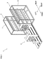
- FIG. 1 is a perspective view of the filament winding device 1.
- the filament winding device 1 includes a winder 2 and a pair of creel stands 3 that are provided to the left of and to the right of a rear portion of the winder 2. On the whole, the filament winding device 1 is arranged to be substantially symmetrical in the left-right direction.
- a part of the winder 2, which is sandwiched between the left and right pair of creel stands 3, is not illustrated to avoid complexity in the figure.
- the winder 2 is configured to wind fiber bundles (not illustrated in FIG. 1 ) onto a liner L which is roughly cylindrical in shape.
- Each fiber bundle is formed by, for example, impregnating a thermosetting or thermoplastic synthetic resin material into a fiber material such as carbon fiber.
- a pressure vessel such as a pressure tank
- a member in which dome-shaped small diameter portions are provided on the both sides of a cylindrical large diameter portion as shown in FIG. 1 is used as the liner L.
- the liner L is made of a material such as high-strength aluminum, metal, or resin, for example.
- a thermosetting process such as baking or a cooling process is performed. As a result, a high-strength pressure vessel is obtained as an end product.
- the creel stand 3 is arranged so that bobbins 12 on which fiber bundles are wound are supported in a rotatable manner by a supporting frame 11 that is provided side by side with the winder 2.
- the fiber bundles supplied from the respective bobbins 12 of the creel stand 3 are used for performing helical winding by a later-described helical winding unit 50.
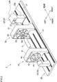
- FIG. 2 is a perspective view of the winder 2.
- FIG. 3 is a profile of the winder 2.
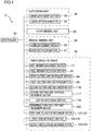
- FIG. 4 is a block diagram of an electric configuration of the winder 2.
- the winder 2 includes a base 20, supporting units 30 (first supporting unit 31 and second supporting unit 32), a hoop winding unit 40, and a helical winding unit 50.
- FIG. 3 does not show the hoop winding unit 40.
- the base 20 supports the supporting units 30, the hoop winding unit 40, and the helical winding unit 50.
- rails 21 are provided to extend in the front-rear direction.
- the supporting units 30 and the hoop winding unit 40 are provided on the rails 21 and are capable of reciprocating in the front-rear direction on the rails 21.
- the helical winding unit 50 is fixed to the base 20.
- the first supporting unit 31, the hoop winding unit 40, the helical winding unit 50, and the second supporting unit 32 are provided in this order from front to rear.
- the supporting units 30 include the first supporting unit 31 which is placed in front of the hoop winding unit 40 and the second supporting unit 32 which is placed behind the helical winding unit 50.
- the supporting units 30 support the liner L so that the liner L is rotatable about a supporting shaft 33 which extends in the front-rear direction (i.e., in the axial direction of the liner L).
- the supporting units 30 include a liner movement motor 34 and a liner rotation motor 35 (see FIG. 4 ).
- the liner movement motor 34 moves the first supporting unit 31 and the second supporting unit 32 in the front-rear direction along the rails 21.
- the liner rotation motor 35 rotates the liner L about the axis by rotating the supporting shaft 33.
- the liner movement motor 34 and the liner rotation motor 35 are driven and controlled by a controller 10 (see FIG. 4 ).
- the second supporting unit 32 includes a base portion 32a that is movable in the axial direction of the liner L and a head portion 32b that is provided above the base portion 32a.
- the head portion 32b is provided with a fiber bundle retainer 60.
- the fiber bundle retainer 60 will be detailed later.
- the hoop winding unit 40 performs hoop-winding on the circumferential surface of the liner L.
- the hoop-winding is a way of winding fiber bundles in a direction substantially perpendicular to the axial direction of the liner L.
- the hoop winding unit 40 includes a main body 41, a rotating member 42, and bobbins 43.
- the main body 41 is provided on the rails 21 and supports the disc-shaped rotating member 42 such that the rotating member 42 is rotatable about the axis of the liner L.
- a circular passing hole 44 is formed to allow the liner L to pass therethrough.
- the rotation member 42 supports the bobbins 43 in a rotatable manner. These bobbins 43 are provided at regular intervals in the circumferential direction around the passing hole 44. A fiber bundle is wound onto each bobbin 43.
- the hoop winding unit 40 includes a movement motor and a rotation motor that are not illustrated.
- the movement motor moves the main body 41 in the front-rear direction along the rails 21.
- the rotation motor rotates the rotation member 42 about the axis of the liner L.
- the movement motor and the rotation motor are driven and controlled by the controller 10 (see FIG. 4 ).
- the controller 10 rotates the rotation member 42 while reciprocating the main body 41 along the rails 21. As a result, the fiber bundles are pulled out from the bobbins 43 rotating around the liner L, and the fiber bundles are simultaneously hoop-wound onto the circumferential surface of the liner L.
- the helical winding unit 50 performs helical-winding on the circumferential surface of the liner L.
- the helical-winding is a way of winding fiber bundles in a direction substantially parallel to the axial direction of the liner L.
- the helical winding unit 50 includes a main body 51, a frame member 52, and plural nozzle units 53. Although the number of the nozzle units 53 is 9 in the present embodiment, the number of the nozzle units 53 is not limited to this.
- the main body 51 is fixed to the base 20.
- the frame member 52 is a disc-shaped member attached to the main body 51. At a central portion of the frame member 52, a circular passing hole 54 is formed to allow the liner L to pass therethrough in the front-rear direction.
- the nozzle units 53 are provided at equal angular intervals in the circumferential direction of the liner L and are provided in a radial manner on the whole. Each nozzle unit 53 is fixed to the frame member 52.
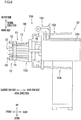
- FIG. 5(a) and FIG. 5(b) are front elevations of the helical winding unit 50.
- FIG. 5(a) shows a situation when the fiber bundles F are wound onto the large diameter portion of the liner L.
- FIG. 5(b) shows a situation when the fiber bundles F are wound onto the small diameter portion of the liner L.
- each nozzle unit 53 includes a guide member 58 (fiber bundle guide of the present invention) that guides the fiber bundle F to the liner L.
- the guide member 58 extends in the radial direction of the liner L (hereinafter, this direction may be simply referred to as a radial direction), is movable in the radial direction, and is rotatable about a rotational axis extending in the radial direction.
- a guide roller 55 is provided on the outer side of the nozzle unit 53 in the radial direction. The fiber bundle F pulled out from each bobbin 12 of the creel stand 3 (see FIG. 1 ) passes via the guide roller 55 through the guide member 58 and reaches the liner L.
- the helical winding unit 50 includes a guide movement motor 56 and a guide rotation motor 57 (see FIG. 4 ).
- the guide movement motor 56 moves the guide members 58 of the respective nozzle units 53 altogether in the radial direction.
- the guide rotation motor 57 rotates the guide members 58 of the respective nozzle units 53 altogether about the respective rotational axes.
- the guide movement motor 56 and the guide rotation motor 57 are driven and controlled by the controller 10 (see FIG. 4 ).
- the controller 10 causes the liner L to pass through the passing hole 54 while slowly rotating the liner L about the axis, by driving and controlling the supporting unit 30.
- the controller 10 suitably moves the guide member 58 of each nozzle unit 53 in the radial direction (i.e., causes the guide member 58 to perform elongation or contraction) and rotates the guide member 58 about the rotational axis (i.e., causes the guide member 58 to perform rotation) .
- the fiber bundle F is pulled out from the guide member 58 of each nozzle unit 53, and the fiber bundles F are simultaneously helical-wound onto the circumferential surface of the rotating liner L.
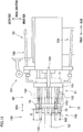
- FIG. 6 is a profile of the second supporting unit 32 including the fiber bundle retainer 60.
- FIG. 7(a) is a profile of a later-described reel member 61.
- FIG. 7(b) is a perspective view of the reel member 61 and a later-described first cutting unit 62. It is noted that FIG. 7(a) and FIG. 7(b) do not show a later-described remaining yarn remover 100.
- FIG. 6 is a profile of the second supporting unit 32 including the fiber bundle retainer 60.
- FIG. 7(a) is a profile of a later-described reel member 61.
- FIG. 7(b) is a perspective view of the reel member 61 and a later-described first cutting unit 62. It is noted that FIG. 7(a) and FIG. 7(b) do not show a later-described remaining yarn remover 100.
- FIG. 7(a) is a profile of a later-described reel member 61.
- FIG. 7(b) is
- the front side of the figure will be referred to as a leading end side in the axial direction (one side in the present invention), whereas the rear side of the figure will be referred to as a base end side in the axial direction (the other side in the present invention).
- the fiber bundle retainer 60 is an apparatus that temporarily retains fiber bundles F when, for example, the liner L is replaced. In addition to this, the fiber bundle retainer 60 may temporarily retain fiber bundles F when a new liner L is supported by the supporting unit 30, for example. As shown in FIG. 6 , FIG. 7(a), and FIG. 7(b) , the fiber bundle retainer 60 includes the reel member 61 and the first cutting unit 62.
- the reel member 61 is configured to be able to retain the fiber bundles F supplied through the guide members 58.
- the reel member 61 includes a base portion 71 and an outer peripheral portion 72.
- the base portion 71 is a ring-shaped member that is attached to a front end portion of the head portion 32b of the second supporting unit 32 and surrounds a supporting shaft 33 in the circumferential direction of the liner L.
- shaft members 73 are attached to be aligned in the circumferential direction of the liner L. The shaft members 73 extend toward the front side (leading end side in the axial direction).
- the outer peripheral portion 72 is supported by the base portion 71 via the shaft members 73.
- the outer peripheral portion 72 includes a ring member 74 and pins 75.
- the ring member 74 is attached to the leading ends of the shaft members 73 and is provided to surround the supporting shaft 33 in the circumferential direction.
- On the outer circumferential surface of the ring member 74 a groove 74a is formed to extend in the axial direction of the liner L and extend inward in the radial direction of the liner L. (The reason of this arrangement will be described later.)
- the pins 75 are attached to an end face of the ring member 74 on the leading end side in the axial direction, and extend toward the leading end side in the axial direction.
- the pins 75 are provided at equal angular intervals in the circumferential direction of the liner L (hereinafter, this direction may be simply referred to as circumferential direction).
- the reel member 61 is movable in the axial direction relative to the head portion 32b by a movement mechanism 76 formed of, for example, a rack-and-pinion mechanism (see an arrow 201 in FIG. 7 (a) ).
- the movement mechanism 76 is driven by a reel member movement motor 77 (see FIG. 4 ).
- the reel member 61 is rotationally driven by a reel member rotation motor 78 (see FIG. 4 ) about the supporting shaft 33 (i.e., about the axis of the liner L) (see an arrow 202 in FIG. 7(a) ).
- the reel member movement motor 77 and the reel member rotation motor 78 are driven and controlled by the controller 10 (see FIG. 4 ). With this arrangement, the reel member 61 is able to wind the fiber bundles F supplied through the guide members 58 onto the outer peripheral portion 72 (as detailed later).
- the first cutting unit 62 is configured to cut parts of the fiber bundles F, which are between parts wound onto the outer peripheral portion 72 of the reel member 61 and parts wound onto the liner L.
- the first cutting unit 62 includes a frame 81 and a cutter 82.
- the frame 81 is a hollow cylindrical member provided inside the ring member 74 in the radial direction of the liner L.
- the cutter 82 is, for example, a rotatable circular blade.
- the cutter 82 is rotatably supported by a supporting member 83 that is attached to a leading end portion in the axial direction of the frame 81.
- the cutter 82 is provided on the inner side of the pins 75 in the radial direction of the liner L.
- the frame 81 may not be hollow cylindrical in shape, and may be ring-shaped.
- the frame 81 is movable in the axial direction relative to the reel member 61 by a first cutting unit movement motor 84 (see FIG. 4 ).
- the movement of the frame 81 in the axial direction is performed mainly for aligning the cutter 82.
- the frame 81 is rotatable about the supporting shaft 33 by a first cutting unit rotation motor 85 (see FIG. 4 ).
- the first cutting unit movement motor 84 and the first cutting unit rotation motor 85 are driven and controlled by the controller 10 (see FIG. 4 ).
- the cutter 82 is movable in the axial direction and rotatable about the supporting shaft 33 together with the frame 81 (see arrows in FIG. 7(b) ). With this arrangement, the first cutting unit 62 is able to cut parts of the fiber bundles F, which are between parts wound onto the outer peripheral portion 72 of the reel member 61 and parts wound onto the liner L, in the circumferential direction.
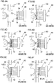
- FIG. 8(a) to FIG. 8(d) only the helical winding unit 50, the liner L, the reel member 61, the first cutting unit 62, and the fiber bundles F are schematically shown for simplicity.
- the controller 10 controls the reel member movement motor 77 (see FIG. 4 ) to move the reel member 61 toward the liner L1 in the axial direction (see FIG. 8(b) ) and inserts the pins between the fiber bundles F in the circumferential direction. Thereafter, the controller 10 controls the reel member rotation motor 78 to rotate the reel member 61 about the axis of the liner L1 (see FIG. 8(c) ). As a result, the fiber bundles F are wound onto the outer peripheral portion 72 of the reel member 61 and retained (see FIG. 8(c) ).
- the controller 10 controls the first cutting unit movement motor 84 (see FIG. 4 ) to position the cutter 82.
- the controller 10 controls the first cutting unit rotation motor 85 (see FIG. 4 ) to rotate the cutter 82 about the axis of the liner L1.
- the fiber bundles F are cut in the circumferential direction.
- parts of the fiber bundles F which are between parts wound onto the outer peripheral portion 72 of the reel member 61 and parts wound onto the liner L1, are cut (see FIG. 8(d) ).
- the operator detaches the liner L1 from the supporting unit 30 (see FIG. 2 ) and attaches a new liner L2 (see FIG. 8(e) ) to the supporting unit 30 (liner replacement).
- the controller 10 controls the guide movement motor 56 (see FIG. 4 ) to move the guide members 58 inward in the radial direction.
- the controller 10 controls the liner rotation motor 35 to rotate the liner L2 about the axis.
- the fiber bundles F are wound onto the end portion in the axial direction of the liner L2 (see FIG. 8(e) ).
- the controller 10 controls the first cutting unit movement motor 84 (see FIG. 4 ) to position the cutter 82.
- the controller 10 then controls the first cutting unit rotation motor 85 (see FIG. 4 ) to rotate the cutter 82 about the axis of the liner L2. Consequently, parts of the fiber bundles F, which are between parts wound onto the outer peripheral portion 72 of the reel member 61 and parts wound onto the liner L2, are cut (see FIG. 8(f) ).
- the liner replacement is performed as described above. The above-described replacement may be automatically performed by a machine.
- part of the fiber bundles F remains wound onto the outer peripheral portion 72 of the reel member 61, as a remaining yarn F1.
- a remaining yarn F1 must be removed before the next liner replacement, for example.
- the removal of the remaining yarn F1 includes, for example, an operation to cut the remaining yarn F1 in the axial direction of the liner L. This operation has been troublesome because it is manually performed by an operator.
- the fiber bundles wound onto the liner L are typically impregnated with adhesive resin. This makes the removal further troublesome because, for example, the remaining yarn F1 is adhered to the outer peripheral portion 72 of the reel member 61.
- the fiber bundle retainer 60 of the present embodiment includes a remaining yarn remover 100 that is arranged as described below.
- FIG. 9 is a front elevation of the fiber bundle retainer 60 including the remaining yarn remover 100. The other figures will be described accordingly.
- the remaining yarn remover 100 is attached to the head portion 32b of the second supporting unit 32.
- the remaining yarn remover 100 includes a second cutting unit 101, a pair of first arm units 102 and 103, a pair of second arm units 104 and 105, and a remaining yarn peel-off unit 106.
- Each of the second cutting unit 101, the first arm units 102 and 103, the second arm units 104 and 105, and the remaining yarn peel-off unit 106 has a movable portion.
- all members of the remaining yarn remover 100 are at their initial positions.
- FIG. 10(a) illustrates the structure of the second cutting unit 101.
- the second cutting unit 101 is provided independently from the above-described first cutting unit 62.
- the second cutting unit 101 is arranged to cut the fiber bundles F wound onto the reel member 61 in the front-rear direction (axial direction) .
- the second cutting unit 101 is provided above the reel member 61.
- the second cutting unit 101 includes a rail member 111, a first movable member 112, a second movable member 113, and a cutter 114.
- the first movable member 112 moves in the axial direction along the rail member 111 fixed to the upper end portion of the head portion 32b of the second supporting unit 32.
- the second movable member 113 moves in the radial direction of the liner L along the front end portion of the first movable member 112.
- the cutter 114 attached to the leading end portion of the second movable member 113 to be rotatable cuts the fiber bundles F.
- the rail member 111 is a member extending in the front-rear direction.
- the rail member 111 is fixed to the upper end portion of the head portion 32b of the second supporting unit 32.
- the rail member 111 supports the first movable member 112 to be movable in the front-rear direction (axial direction).
- the first movable member 112 is substantially L-shaped. As shown in FIG. 10(a) , the first movable member 112 includes a bottom portion 112a extending in the front-rear direction and a front portion 112b extending upward from a front end portion of the bottom portion 112a. The bottom portion 112a of the first movable member 112 is supported by the rail member 111 to be movable in the front-rear direction. The front portion 112b supports the second movable member 113 to be movable in the up-down direction. The first movable member 112 is moved in the front-rear direction along the rail member 111 (see an arrow 203 in FIG. 10(a) ) by, for example, a second cutting unit movement motor 116 (see FIG. 4 ). The second cutting unit movement motor 116 is driven and controlled by the controller 10 (see FIG. 4 ).
- the second movable member 113 is a member that extends substantially in the front-rear direction.
- the second movable member 113 is provided above the reel member 61 (see FIG. 9 ).
- the second movable member 113 is supported by the first movable member 112 to be movable in the up-down direction (in this case, this direction is identical with the radial direction of the liner L) (see an arrow 204 in FIG. 10(a) ).
- the cutter 114 is supported by the front end portion of the second movable member 113 to be rotatable.
- the second movable member 113 is moved in the up-down direction along the front portion 112b of the first movable member 112 by, for example, a second cutting unit vertical movement motor 117 (see FIG. 4 ).
- the second cutting unit vertical movement motor 117 is driven and controlled by the controller 10 (see FIG. 4 ).
- the cutter 114 is provided to cut the remaining yarn F1 in the axial direction.
- the cutter 114 is, for example, a rotatable circular blade.
- the cutter 114 is supported by the front end portion of the second movable member 113 to be rotatable about a rotational axis direction which is parallel to the left-right direction.
- FIG. 9 when viewed in the front-rear direction (see FIG. 9 ), the cutter 114 is provided on a vertical line VL passing through the axial center of the reel member 61.
- the cutter 114 is rotationally driven by, for example, a cutter rotation motor 118 (see FIG. 4 ).
- the cutter rotation motor 118 is driven and controlled by the controller 10 (see FIG. 4 ).
- the cutter 114 is movable in the front-rear direction (see an arrow 203 and the second cutting unit 101 indicated by two-dot chain lines in FIG. 10(a) ).
- the cutter 114 is movable in the up-down direction, too (see an arrow 204 and the second cutting unit 101 indicated by one-dot chain lines in FIG. 10(a) ).
- the groove 74a is formed along the axial direction of the liner L in the outer circumferential surface of the ring member 74 of the reel member 61 (see FIG. 7(b) ).
- the groove 74a extends inward in the radial direction of the liner L from the outer circumferential surface of the ring member 74.
- FIG. 10(b) illustrates the structures of the first arm units 102 and 103 and the second arm units 104 and 105.
- the first arm units 102 and 103 are provided mainly to suppress the remaining yarn F1 from slipping forward when the remaining yarn F1 is cut by the second cutting unit 101.
- the first arm units 102 and 103 are provided above the reel member 61, for example.
- the first arm units 102 and 103 are provided on the respective sides of the second cutting unit 101 in the left-right direction (i.e., in the rotational axis direction of the cutter 114).
- the first arm unit 102 is provided to the right of the second cutting unit 101.
- the first arm unit 103 is provided to the left of the second cutting unit 101.
- the first arm unit 102 and the first arm unit 103 are substantially symmetrical in the left-right direction.
- the first arm unit 102 includes members such as an arm member 121, a pressing member 122 (fiber bundle pressing member of the present invention), a first movement mechanism 123, and a second movement mechanism 124.
- the arm member 121 is movable in the longitudinal direction of the arm member 121 by the first movement mechanism 123 and is movable in the radial direction of the liner L by the second movement mechanism 124.
- the pressing member 122 attached to a front end portion of the arm member 121 restricts the movement of the remaining yarn F1 in the axial direction.
- the arm member 121 is a rod-shaped member extending substantially in the front-rear direction. To be more precise, the arm member 121 is inclined forward and inward in the radial direction of the liner L.
- the arm member 121 is supported in a movable manner by a supporting member 125 fixed to an upper portion of the head portion 32b of the second supporting unit 32, via the first movement mechanism 123 and the second movement mechanism 124.
- An attaching member 126 is attached to the front end portion of the arm member 121.
- the attaching member 126 is, for example, a plate-shaped member. As shown in FIG. 9 , the attaching member 126 extends at least in the circumferential direction of the liner L.
- the pressing member 122 is substantially L-shaped. As shown in FIG. 10(b) , the pressing member 122 includes a main body portion 122a extending substantially in the front-rear direction and a claw portion 122b extending substantially in the radial direction of the liner L from a front end portion of the main body portion 122a. At the end portions of the attaching member 126 in the circumferential direction of the liner L, two pressing members 122 are attached, respectively.
- the first movement mechanism 123 is a mechanism configured to move the arm member 121 in the longitudinal direction of the arm member 121.
- the first movement mechanism 123 is, for example, a known rack-and-pinion mechanism.
- the first movement mechanism 123 is supported by the second movement mechanism 124 to be movable in the radial direction of the liner L.
- the first movement mechanism 123 is driven by a first arm telescopic movement motor 127 (see FIG. 4 ).
- the first arm telescopic movement motor 127 is driven and controlled by the controller 10 (see FIG. 4 ). With this arrangement, the arm member 121 moves in the longitudinal direction of the arm member 121 (see an arrow 205 and the arm member 121 indicated by two-dot chain lines in FIG. 10(b) , etc.)
- the second movement mechanism 124 is a mechanism configured to move the arm member 121 in the radial direction of the liner L.
- the second movement mechanism 124 is, for example, a known ball screw mechanism.
- the second movement mechanism 124 is attached to the supporting member 125.
- the second movement mechanism 124 supports the first movement mechanism 123 so that the first movement mechanism 123 is movable in the radial direction of the liner L.
- the second movement mechanism 124 is driven by a first arm movement motor 128 (see FIG. 4 ).
- the first arm movement motor 128 is driven and controlled by the controller 10 (see FIG. 4 ).
- the arm member 121 moves in the radial direction of the liner L, together with the first movement mechanism 123 (see an arrow 206 and the arm member 121 indicated by one-dot chain lines in FIG. 10(b) , etc.)
- the first arm unit 103 includes members such as an arm member 131, a pressing member 132 (fiber bundle pressing member of the present invention), a first movement mechanism 133, and a second movement mechanism 134 (see FIG. 9 ).
- the pressing member 132 includes a claw portion 132b.
- the first movement mechanism 133 of the first arm unit 103 is driven by a first arm telescopic movement motor 137 (see FIG. 4 ) which is different from the first arm telescopic movement motor 127.
- the second movement mechanism 134 of the first arm unit 103 is driven by a first arm movement motor 138 (see FIG. 4 ) which is different from the first arm movement motor 128.
- the second arm units 104 and 105 are provided to receive the remaining yarn F1 peeled off from the reel member 61. As shown in FIG. 9 , the second arm units 104 and 105 are provided below the reel member 61. The second arm unit 104 and the second arm unit 105 are substantially symmetrical in the left-right direction.
- the second arm unit 104 includes an arm member 141, a receiver 142, and a movement mechanism 143.
- the arm member 141 is, for example, a member similar to the arm member 121 of the first arm unit 102.
- the receiver 142 is, for example, a member similar to the pressing member 122 of the first arm unit 102.
- the movement mechanism 143 is, for example, a mechanism similar to the first movement mechanism 123 of the first arm unit 102.
- the movement mechanism 143 is driven by a second arm telescopic movement motor 144 (see FIG. 4 ).
- the second arm telescopic movement motor 144 is driven and controlled by the controller 10 (see FIG. 4 ).
- the arm member 141 moves in the longitudinal direction of the arm member 141 (see an arrow 207 and the arm member 141 indicated by two-dot chain lines in FIG. 10(b) , etc.).
- the second arm unit 105 includes an arm member 151, a receiver 152, and a movement mechanism 153 (see FIG. 9 ).
- the movement mechanism 153 is driven by a second arm telescopic movement motor 154 (see FIG. 4 ).
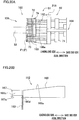
- FIG. 11 shows the structure of the remaining yarn peel-off unit 106.
- the remaining yarn peel-off unit 106 is indicated by full lines whereas the reel member 61 is indicated by two-dot chain lines.
- FIG. 12(a) illustrates a later-described first peel-off portion 162.
- FIG. 12(b) illustrates a later-described second peel-off portion 163.
- FIG. 13 shows the traveling range of the remaining yarn peel-off unit 106.
- the profiles such as FIG. 13 only show some of later-described first peel-off portions 162 for the sake of simplicity.
- the remaining yarn peel-off unit 106 is provided to facilitate the removal of the remaining yarn F1 adhered to the outer peripheral portion 72 of the reel member 61 and the remaining yarn F1 entwined around the pins 75, after the remaining yarn F1 is cut by the second cutting unit 101. As shown in FIG. 6 and FIG. 11 , the remaining yarn peel-off unit 106 is attached to the reel member 61. As shown in FIG. 11 , the remaining yarn peel-off unit 106 includes a base portion 161, first peel-off portions 162, and a second peel-off portion 163. In order to improve the visibility, the first peel-off portions 162 are hatched in FIG. 11 .
- the remaining yarn peel-off unit 106 moves toward the leading end side in the axial direction of the liner L so as to lift up the remaining yarn F1 from the outer peripheral portion 72 of the reel member 61 outward in the radial direction by the first peel-off portions 162 and to push out the remaining yarn F1 toward the leading end side in the axial direction by the second peel-off portion 163.
- the base portion 161 is formed of, for example, a ring-shaped member.
- the base portion 161 is provided to surround the reel member 61 in the circumferential direction (i.e., to surround the above-described supporting shaft 33).
- the base portion 161 is provided in front of the base portion 71 of the reel member 61 (see FIG. 13 ).
- Plural first peel-off portions 162 are attached to the front end face of the base portion 161.
- the base portion 161 is movable in the axial direction of the liner L by a movement mechanism 164 that is formed of, for example, a rack-and-pinion mechanism.
- the movement mechanism 164 is driven by a remaining yarn peel-off unit movement motor 165 (see FIG. 4 ).
- the remaining yarn peel-off unit movement motor 165 is driven and controlled by the controller 10 (see FIG. 4 ).
- the first peel-off portion 162 is a rod-shaped member extending in the axial direction of the liner L. As shown in FIG. 11 , the first peel-off portions 162 are fixed to the front end face of the base portion 161 and are movable in the axial direction together with the base portion 161. In the present invention, nine first peel-off portions 162 are aligned in the circumferential direction of the liner L. The angular intervals of the first peel-off portions 162 in the circumferential direction are identical except at one interval. On the base portion 161, no first peel-off portion 162 is attached to the uppermost part (i.e., the 12 o'clock position).
- the first peel-off portions 162 are provided not to interfere with the cutter 114 when the remaining yarn F1 is cut by the above-described second cutting unit 101 (see e.g., FIG. 6 ).
- the second peel-off portion 163 is supported to be movable in the axial direction relative to the first peel-off portions 162.
- each first peel-off portion 162 includes a main body 166 and a leading end member 167 fixed to the tip of the main body 166 in the axial direction.
- the main body 166 has an inclined surface 166a (contact surface of the present invention).
- the inclined surface 166a is provided to make contact with the remaining yarn F1 from the inner side in the radial direction of the liner L so as to push the remaining yarn F1 outward in the radial direction.
- the inclined surface 166a is inclined outward in the radial direction of the liner L toward the base end side in the axial direction of the liner L.
- the inclined surface 166a is at least partially outside the outer peripheral portion 72 of the reel member 61 in the radial direction.
- a supporter 166b is provided to support the second peel-off portion 163 so that the second peel-off portion 163 is movable in the axial direction.
- This arrangement will be specifically described below.
- a cutout is formed by a face 166c that is orthogonal to the radial direction and a face 166d that is orthogonal to the axial direction and is connected to a side on the base end side in the axial direction of the face 166c.
- a part of the main body 166 where the cutout is formed is the supporter 166b.
- the supporter 166b is fitted into a later-described groove 172 of the second peel-off portion 163 to be movable.
- the face 166d restricts the movement of the second peel-off portion 163 toward the base end side in the axial direction.
- the face 166d will be referred to as a first regulating surface 166d (first regulatory portion of the present invention).
- the leading end member 167 protrudes inward in the radial direction relative to the supporter 166b. An end face on the base end side in the axial direction of the leading end member 167 is therefore partially exposed. This exposed portion will be referred to as a second regulating surface 167a (second regulatory portion of the present invention).
- the second regulating surface 167a restricts the movement of the second peel-off portion 163 toward the leading end side in the axial direction.
- the second peel-off portion 163 is provided to mainly push the remaining yarn F1 entwined around the pins 75 toward the leading end side in the axial direction of the liner L.
- the second peel-off portion 163 is formed of a ring-shaped member.
- the second peel-off portion 163 is provided to surround the above-described supporting shaft 33 in the circumferential direction of the liner L.
- the second peel-off portion 163 has plural through holes 171 (through holes of the present invention) penetrating the portion in the axial direction. Each through hole 171 has an inner diameter slightly larger than the diameter of the pin 75 described above.
- the second peel-off portion 163 When the second peel-off portion 163 is at an initial position (hereinafter, the initial position of the second peel-off portion 163 will be referred to as a retracted position), a pin 75 is inserted into each through hole 171.
- grooves 172 are formed to extend inward in the radial direction of the liner L.
- the position of one (groove 172a shown in FIG. 12(b) ) of the grooves 172 in the circumferential direction corresponds to the position of the above-described groove 74a of the ring member 74 of the reel member 61 in the circumferential direction.
- the above-described supporters 166b of the first peel-off portion 162 are fitted into the remaining grooves 172.
- the second peel-off portion 163 is supported by the first peel-off portions 162 aligned in the circumferential direction, so as to be movable in the axial direction relative to the first peel-off portions 162.
- the second peel-off portion 163 is arranged to be movable relative to the first peel-off portions 162 within a range in which the supporters 166b of the first peel-off portions 162 are provided in the axial direction (see an arrow 208 in FIG. 12(b) ).
- the movement of the second peel-off portion 163 toward the base end side in the axial direction is restricted by the first regulating surface 166d of the first peel-off portion 162 and the movement of the second peel-off portion 163 toward the leading end side in the axial direction is restricted by the second regulating surface.
- the second peel-off portion 163 is movable in the axial direction relative to the first peel-off portions 162 by the distance A.
- the second peel-off portion 163 is separated from the first regulating surface 166d and in contact with the second regulating surface 167a (see e.g., full lines in FIG. 12(a) ).
- the base portion 161 and the first peel-off portions 162 are movable between a predetermined standby position (see full lines in FIG. 13 ) and a protruding position (contact position of the present invention; indicated by two-dot chain lines in FIG. 13 ) which is on the front side (leading end side in the axial direction) of the standby position (see an arrow 209 in FIG. 13 ).
- the distance B that is the movable distance of the first peel-off portions 162 i.e., the distance between the standby position and the protruding position in the axial direction shown in FIG. 13
- the distance A is shorter than the distance B.
- the operation of the remaining yarn peel-off unit 106 will be further detailed later.
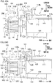
- FIG. 14(a) and FIG. 14(b) show the operations of the first arm unit 102 and the second arm unit 104.
- FIG. 15 shows the pressing members 122 and 132 shown in FIG. 14(b) and their surroundings, which are viewed in the front-rear direction.
- FIG. 16(a) shows the operations of the first arm unit 102 and the second cutting unit 101.
- FIG. 16(b) shows an operation of cutting the remaining yarn F1 by the second cutting unit 101.
- FIG. 17 shows the pressing members 122 and 132 and the cutter 114 shown in FIG. 16(b) and their surroundings, which are viewed in the front-rear direction.
- FIG. 15 shows the pressing members 122 and 132 shown in FIG. 14(b) and their surroundings, which are viewed in the front-rear direction.
- FIG. 16(a) shows the operations of the first arm unit 102 and the second cutting unit 101.
- FIG. 16(b) shows an operation of cutting the remaining yarn F1 by the second cutting unit 101.
- FIG. 18 show the operations of the first arm units 102 and 103.
- FIG. 19(a) and FIG. 19(b) show the remaining yarn peel-off unit 106 at an initial position.
- FIG. 20(a), FIG. 20(b) , FIG. 21(a), and FIG. 21(b) illustrate the operation of the remaining yarn peel-off unit 106.
- FIG. 22(a) and FIG. 22(b) show the operation of the first arm unit 102 after the completion of the operation of the remaining yarn peel-off unit 106.
- the controller 10 controls the first arm telescopic movement motors 127 and 137 to drive the first movement mechanisms 123 and 133.
- the arm member 121 moves in the longitudinal direction of the arm member 121 (see an arrow 210 in FIG. 14(a) ) and the arm member 131 moves in the longitudinal direction of the arm member 131.
- the claw portion 122b of the pressing member 122 and the claw portion 132b of the pressing member 132 move to locations on the leading end side of the pins 75 of the reel member 61.
- the controller 10 controls the first arm movement motors 128 and 138 to drive the second movement mechanisms 124 and 134.
- the arm members 121 and 131 move inward in the radial direction of the liner L (see an arrow 212 in FIG. 14(b) ).
- part of the claw portion 122b of the pressing member 122 and part (on the leading end side) of the claw portion 132b of the pressing member 132 are located just in front of the remaining yarn F1.
- the pressing members 122 and 132 oppose each other over the second cutting unit 101 in the left-right direction (see FIG. 15 ).
- the controller 10 controls the second arm telescopic movement motors 144 and 154 to drive the movement mechanisms 143 and 153.
- the arm member 141 moves in the longitudinal direction of the arm member 141 (see an arrow 211 in FIG. 14(a) ) and the arm member 151 moves in the longitudinal direction of the arm member 151.
- the receivers 142 and 152 move to a location directly below the outer peripheral portion 72 of the reel member 61 or to a location in the vicinity of that location.
- the controller 10 may simultaneously drive all of the first arm units 102 and 103 and the second arm units 104 and 105.
- the controller 10 controls the second cutting unit movement motor 116 (see FIG. 4 ) and the second cutting unit vertical movement motor 117 (see FIG. 4 ) to move the cutter 114 in the axial direction of the liner L and in the radial direction of the liner L (see arrows 213 and 214 in FIG. 16(a) ).
- the controller 10 moves the cutter 114 to a location in the vicinity of the outer peripheral portion 72 of the reel member 61 (i.e., immediately behind the remaining yarn F1).
- the cutter 114 is positioned at a location in the vicinity of the uppermost part of the remaining yarn F1 (i.e., the part at the 12 o'clock position) .
- the controller 10 may start the movement of the cutter 114 after moving the first arm units 102 and 103 and the second arm units 104 and 105 as described above. Alternatively, the controller 10 may move the first arm units 102 and 103, the second arm units 104 and 105, and the cutter 114 at the same time.
- the controller 10 controls the first arm telescopic movement motor 127 (see FIG. 4 ) to move the arm member 121 to the base end side in the axial direction (see an arrow 215 in FIG. 16(a) ) and to insert the claw portion 122b between the pins 75.
- the controller 10 controls the first arm telescopic movement motor 137 (see FIG. 4 ) to move the arm member 131 to the base end side in the axial direction.
- the remaining yarn F1 is pressed from the leading end side in the axial direction, by the claw portions 122b and 132b.
- the controller 10 then moves the cutter 114 forward (toward the leading end side in the axial direction) (see an arrow 216 in FIG. 16(b) ) while rotating the circular blade by controlling the cutter rotation motor 118 (see FIG. 4 ).
- the uppermost part of the remaining yarn F1 in the vertical direction is cut in the axial direction.
- the remaining yarn F1 is pressed from the leading end side in the axial direction by the claw portion 122b of the pressing members 122 and the claw portion 132b of the pressing member 132 (see FIG. 17 ).
- the movement of the remaining yarn F1 toward the leading end side in the axial direction is restricted when the remaining yarn F1 is cut by the second cutting unit 101.
- the pressing members 122 and 132 oppose each other over the second cutting unit 101 in the left-right direction (see FIG. 17 ). It is therefore possible to suppress the deviation of the remaining yarn F1 toward the leading end side in the axial direction.
- the groove 74a is formed in the ring member 74 of the reel member 61 whereas the groove 172a is formed in the second peel-off portion 163 of the remaining yarn peel-off unit 106. This arrangement ensures the inward movement of the cutter 114 in the radial direction of the liner L (see FIG. 17 ), and hence the remaining yarn F1 can be further reliably cut.
- the controller 10 moves the arm members 121 and 131 further toward the leading end side (see an arrow 217 in FIG. 18 ). (In FIG. 18 , the arm member 131 is not shown.) As a result, the pressing members 122 and 132 are moved to locations in front of the remaining yarn F1 immediately after being cut by the second cutting unit 101. Because the pressing members 122 and 132 are positioned at these locations, it is possible to prevent the remaining yarn F1 from hitting the helical winding unit 50 (see, e.g., FIG. 3 ) when the remaining yarn F1 is pushed out by the remaining yarn peel-off unit 106 as described below.
- the controller 10 controls the remaining yarn peel-off unit movement motor 165 (see FIG. 4 ) to drive the movement mechanism 164, and move the remaining yarn peel-off unit 106 forward (toward the leading end side in the axial direction).
- the second peel-off portion 163 is detached from the first regulating surface 166d of the first peel-off portion 162 (see FIG. 19(b) ) as described above.
- the movement mechanism 164 starts to drive, the base portion 161 and the first peel-off portions 162 start to move toward the leading end side in the axial direction, whereas the second peel-off portion 163 moves relative to the first peel-off portions 162. (In other words, the second peel-off portion 163 does not move relative to the reel member 61).
- the movable range (distance A shown in FIG. 12(a) ) of the second peel-off portion 163 in the axial direction of the liner L is shorter than the movable range (distance B shown in FIG. 13 ) of the first peel-off portion 162 in the axial direction.
- the first regulating surface 166d makes contact with the second peel-off portion 163 during the movement of the first peel-off portion 162, as shown in FIG. 20(a) and FIG. 20(b) .
- the second peel-off portion 163 is therefore pressed by the first regulating surface 166d (see FIG. 21(a) and FIG. 21(b) ) and moved toward the leading end side in the axial direction together with the first peel-off portion 162 (see arrows 219 and 220 in FIG. 21(a) ). As such, the second peel-off portion 163 is moved from the retracted position to a pushing position. As a result, the remaining yarn F1 entwined around the pins 75 of the reel member 61 is pushed toward the leading end side in the axial direction by the second peel-off portion 163 (see FIG. 21(a) ).
- the remaining yarn F1 having been pushed toward the leading end side in the axial direction is received by, for example, the pressing member 122 of the first arm unit 102 (see FIG. 22(a) ). It is therefore possible to prevent the remaining yarn F1 from hitting the helical winding unit 50 (see, e.g., FIG. 3 ) .
- the controller 10 controls the first arm telescopic movement motor 127 (see FIG. 4 ) to move the arm member 121 outward in the radial direction and toward the base end side in the axial direction (see an arrow 221 in FIG. 22(b) ).
- the controller 10 controls the first arm telescopic movement motor 137 (see FIG. 4 ) to move the arm member 131 outward in the radial direction and toward the base end side in the axial direction.
- the remaining yarn F1 is hooked by the claw portion 122b of the pressing member 122 and the claw portion 132b of the pressing member 132, and the remaining yarn F1 is further peeled by the claw portions 122b and 132b.
- the remaining yarn F1 is easily removable from the outer peripheral portion 72 of the reel member 61.
- the controller 10 for example, rotates the reel member 61 about the axis of the liner L, the remaining yarn F1 drops onto the second arm units 104 and 105 by its own weight, with the result that the remaining yarn F1 is removed from the reel member 61.
- all components of the remaining yarn remover 100 are returned to the initial positions.
- the first peel-off portion 162 is returned from the contact position to the standby position
- the second peel-off portion 163 is moved by the second regulating surface 167a toward the base end side in the axial direction back to the retracted position.
- the second cutting unit 101 is able to cut the remaining yarn F1 in the axial direction. This makes it easy to remove the remaining yarn F1 from the outer peripheral portion 72. The time and labor required for removing the remaining yarn F1 are therefore reduced.
- the pressing members 122 and 132 make it possible to suppress the remaining yarn F1 from slipping in the axial direction and being deviated, when the second cutting unit 101 cuts the remaining yarn F1. Smooth cutting of the remaining yarn F1 is therefore facilitated.
- the remaining yarn F1 having been cut by the second cutting unit 101 is lifted up from the outer peripheral portion 72 by the first peel-off portion 162. It becomes further easy to remove the remaining yarn F1.
- the inclined surface 166a causes the remaining yarn F1 to be lifted outward in the radial direction from the outer peripheral portion 72. As such, the remaining yarn F1 can be lifted up from the outer peripheral portion 72 by a simple arrangement.
- the operation of the second peel-off portion 163 after the start of the operation of the first peel-off portion 162.
- the operation of the second peel-off portion 163 can be started after the remaining yarn F1 is lifted up from the outer peripheral portion 72 to some degree by the first peel-off portion 162. This makes it easy to peel off the remaining yarn by the second peel-off portion 163.
- the first peel-off portion 162 is returned from the contact position to the standby position, the second peel-off portion 163 is moved by the second regulating surface 167a toward the base end side in the axial direction.
- the uppermost part of the remaining yarn F1 in the vertical direction is cut by the second cutting unit 101. This makes it easy to cause the remaining yarn F1 having been cut in the axial direction to drop off from the reel member 61 by its own weight. It becomes more easy to remove the remaining yarn F1.
Landscapes
- Engineering & Computer Science (AREA)
- Mechanical Engineering (AREA)
- Chemical & Material Sciences (AREA)
- Composite Materials (AREA)
- Textile Engineering (AREA)
- Moulding By Coating Moulds (AREA)
Abstract
Description
- The present invention relates to a filament winding device which winds a fiber bundle onto a liner.
- A filament winding device recited in Patent Literature 1 includes a liner transporter and a helical winding device. The liner transporter supports a liner to be movable in the axial direction and rotatable about the axis. The helical winding device includes fiber bundle guides that guide fiber bundles to the liner. As the liner rotates and moves in a state in which leading end portions of the fiber bundles are fixed to the surface of the liner, the fiber bundles are supplied to the liner through the guides and helical winding is achieved.
- The filament winding device further includes a yarn end processor (fiber bundle retainer) that temporarily retains the fiber bundles when the liner is replaced. The fiber bundle retainer includes a reel member on which the fiber bundles are temporarily wound in the circumferential direction of the liner and a cutter by which the fiber bundles are cut as described below. To be more specific, the reel member has pins that are aligned in the circumferential direction, are movable in the axial direction of the liner, and are rotatable about the axis of the liner.
- After the completion of the helical winding to a liner, the pins move toward the liner in the axial direction, and enter into the fiber bundles in the circumferential direction. As the pins rotate about the axis of the liner, the fiber bundles are wound onto the pins and their surroundings. Then a part of each fiber bundle, which is between the liner and the reel member, is cut by the cutter. As a result, it becomes possible to replace the liner on which the helical winding has been completed with a new liner. The leading end portions of the fiber bundles supplied through the guides are temporarily retained by the reel member. The fiber bundles retained by the reel member are then wound onto an end portion in the axial direction of the liner that has been newly attached to the liner transporter. Then a part of each fiber bundle, which is between the new liner and the reel member, is cut by the cutter. In this way, it is possible to start the helical winding onto the new liner.
- [Patent Literature 1]
Japanese Patent No. 5643322 - In the fiber bundle retainer of Patent Literature 1, it is necessary to remove a remaining fiber bundle (remaining yarn) wound onto the reel member after the part of each fiber bundle between the new liner and the reel member is cut. The removal of the remaining yarn includes, for example, an operation to cut the remaining yarn in the axial direction of the liner. This operation is troublesome because it is manually performed by an operator.
- An object of the present invention is to reduce the time and labor required for the removal of a remaining yarn.
- According to a first aspect of the invention, a filament winding device includes: a liner supporter which supports a liner to be rotatable about an axis of the liner; and a helical winding unit which includes fiber bundle guides that are aligned in a circumferential direction of the liner and guide fiber bundles to the liner, the filament winding device helical-winding the fiber bundles supplied through the fiber bundle guides onto the rotating liner by moving the liner supporter and the helical winding unit relative to each other in an axial direction of the liner, the filament winding device further comprising a fiber bundle retainer which is configured to temporarily retain the fiber bundles at least when the liner is replaced, and the fiber bundle retainer including: a reel member which includes an outer peripheral portion having pins that are movable in the axial direction relative to the fiber bundles supplied through the fiber bundle guides and are rotatable about the axis of the liner, the reel member being capable of winding the fiber bundles onto the outer peripheral portion; a first cutting unit which is configured to cut a part of each of the fiber bundles in the circumferential direction, the part being between a part of the fiber bundle wound on the outer peripheral portion and a part of the fiber bundle wound on the liner; and a second cutting unit which is different from the first cutting unit and is configured to cut a part of each of the fiber bundles in the axial direction, the part being wound on the outer peripheral portion.
- To begin with, after helical-winding onto a liner, the pins of the reel member move in a relative manner toward the liner and rotate in the circumferential direction while the pins are inserted into the fiber bundles, with the result that the fiber bundles are wound onto the outer peripheral portion. Then a part of each fiber bundle, which is between the liner and the reel member, is cut by the first cutting unit. When the liner on which the helical-winding has been done is, for example, replaced with a new liner, the leading end portions of the fiber bundles supplied through the guides are temporarily retained by the reel member. The fiber bundles retained by the reel member are then fixed to an end portion in the axial direction of the new liner. A part of the fiber bundle between the reel member and the liner is cut by the first cutting unit. Thereafter, it becomes necessary to remove a fiber bundle (remaining yarn) remaining on the outer peripheral portion of the reel member. The operation will be detailed in the embodiment below.
- Furthermore, according to the present invention, the second cutting unit is able to cut the remaining yarn in the axial direction. This makes it easy to remove the remaining yarn from the outer peripheral portion. The time and labor required for removing the remaining yarn are therefore reduced.
- According to a second aspect of the invention, the filament winding device of the first aspect is arranged such that the second cutting unit cuts the fiber bundles by moving toward one side in the axial direction, and the fiber bundle retainer includes at least one fiber bundle pressing member which is configured to restrict movement of the fiber bundles wound on the outer peripheral portion of the reel member toward the one side in the axial direction.
- When the remaining yarn is cut by the second cutting unit, if the remaining yarn is pushed by the second cutting unit moving in the axial direction, the remaining yarn may slip in the axial direction and may not be smoothly cut. According to the present invention, the slipping and deviation of the remaining yarn in the axial direction are suppressed by the fiber bundle pressing member. Smooth cutting of the remaining yarn is therefore facilitated.
- According to a third aspect of the invention, the filament winding device of the second aspect is arranged such that the at least one fiber bundle pressing member comprises plural fiber bundle pressing members, and the fiber bundle pressing members are provided to oppose each other over the second cutting unit.
- Because the movement of the remaining yarn in the axial direction is restricted on the both sides over the second cutting unit in the present invention, it is possible to further ensure the suppression of the deviation of the remaining yarn in the axial direction.
- According to a fourth aspect of the invention, the filament winding device of any one of the first to third aspects is arranged such that the fiber bundle retainer includes a first peel-off portion which is movable between a predetermined standby position and a contact position different from the standby position, and the first peel-off portion moves from the standby position to the contact position and makes contact with the fiber bundles wound on the outer peripheral portion of the reel member from inside in the radial direction of the liner, so as to lift up the bundles outward in the radial direction.
- Because the fiber bundles are wound so as to be entwined with the outer peripheral portion including the pins, the remaining yarn may not be easily removed even after the remaining yarn is cut in the axial direction by the second cutting unit. According to the present invention, the remaining yarn having been cut by the second cutting unit is lifted up from the outer peripheral portion by the first peel-off portion. It becomes more easy to remove the remaining yarn.
- According to a fifth aspect of the invention, the filament winding device of the fourth aspect is arranged such that the contact position is on one side of the standby position in the axial direction, the first peel-off portion has a contact surface which extends outward in the radial direction toward the other side in the axial direction and is provided at least partially outside the outer peripheral portion in the radial direction, and the first peel-off portion is movable in the axial direction.
- For example, the first peel-off portion may be arranged to be movable in the radial direction. This arrangement, however, is disadvantageous in that the structure of the fiber bundle retainer may become complicated. According to the present invention, the remaining yarn can be lifted up outwardly in the radial direction from the outer peripheral portion by the contact surface, as the first peel-off portion is simply moved in the axial direction. As such, the remaining yarn can be lifted up from the outer peripheral portion by a simple arrangement.
- According to a sixth aspect of the invention, the filament winding device of the fifth aspect is arranged such that the fiber bundle retainer includes a second peel-off portion which has insertion holes into which the pins are insertable and is movable in a direction in which each of the pins extends, and the second peel-off portion is movable between a retracted position where the pins are inserted into the insertion holes and a pushing position that is closer to leading ends of the pins than the retracted position in the direction in which each of the pins extends.
- As described above, the fiber bundles are wound so as to be entwined with the outer peripheral portion including the pins. At least part of the remaining yarn is therefore typically entwined around each pin, and such a remaining yarn must be removed. According to the present invention, as the second peel-off portion is moved from the retracted position to the pushing position, the remaining yarn entwined around each pin can be pushed out by the second peel-off portion. It is therefore possible to effectively remove the remaining yarn entwined around the pins.
- According to a seventh aspect of the invention, the filament winding device of the sixth aspect of the invention is arranged such that the pins extend along the axial direction, the contact position is closer to the leading ends of the pins than the standby position in the axial direction, the first peel-off portion is movable in the axial direction, the contact surface extends outward in the radial direction toward base ends of the pins in the axial direction, the first peel-off portion includes: a supporter which supports the second peel-off portion to be movable in the axial direction relative to the first peel-off portion; a first regulatory portion which is provided at an end portion on the base end side in the axial direction of the supporter to restrict relative movement of the second peel-off portion toward the base end side; and a second regulatory portion which is provided at an end portion on the leading end side in the axial direction of the supporter to restrict relative movement of the second peel-off portion toward the leading end side, in the axial direction, wherein a distance at which the second peel-off portion is able to move relative to the first peel-off portion is shorter than a distance between the standby position and the contact position, and the second peel-off portion is separated from the first peel-off portion when the first peel-off portion is at the standby position.
- In an arrangement in which the first peel-off portion and the second peel-off portion operate independently, the structure of the fiber bundle retainer may be complicated. Meanwhile, in an arrangement in which the first peel-off portion and the second peel-off portion are fixed to each other, an operation to lift up the remaining yarn by the first peel-off portion and an operation to push out the remaining yarn by the second peel-off portion start at the same time. In other words, pushing of the remaining yarn by the second peel-off portion starts before the remaining yarn is completely lifted up by the first peel-off portion. In such a case, it may be difficult to push out the remaining yarn by the second peel-off portion.
- In the present invention, as described below, the timing to start the operation of the first peel-off portion and the timing to start the operation of the second peel-off portion are arranged to be deviated from each other by a simple arrangement. To begin with, when the first peel-off portion starts to move from the standby position to the contact position in the axial direction, the second peel-off portion is separated from the first regulatory portion (i.e., the second peel-off portion is not in contact with the first regulatory portion). It is therefore possible to move the second peel-off portion relative to the first peel-off portion while the first peel-off portion is moving toward the leading end side in the axial direction. In other words, it is possible to keep the second peel-off portion to be stopped relative to the remaining yarn at least immediately after the start of the movement of the first peel-off portion. It is therefore possible to lift the remaining yarn outward in the radial direction by the contact surface by moving the first peel-off portion while keeping the second peel-off portion to be stopped relative to the remaining yarn.
- In regard to the above, in the axial direction, the distance at which the second peel-off portion is able to move relative to the first peel-off portion is shorter than the distance between the standby position and the contact position. On this account, when the first peel-off portion is further moved toward the leading end side in the axial direction, the first regulatory portion makes contact with the second peel-off portion during the movement of the first peel-off portion. Because the movement of the second peel-off portion toward the base end portion in the axial direction relative to the first regulatory portion is restricted, the second peel-off portion is moved toward the leading end side in the axial direction by the first regulatory portion. In this way, it is possible to start the operation of the second peel-off portion after the start of the operation of the first peel-off portion. On this account, the operation of the second peel-off portion can be started after the remaining yarn is lifted up from the outer peripheral portion to some degree by the first peel-off portion. This makes it easy to peel off the remaining yarn by the second peel-off portion. When the first peel-off portion is returned from the contact position to the standby position, the second peel-off portion is moved by the second regulatory portion toward the base end side in the axial direction.
- According to an eighth aspect of the invention, the filament winding device of any one of the first to seventh aspects is arranged so that the axial direction includes at least a horizontal component, and the second cutting unit cuts the fiber bundles wound on the outer peripheral portion of the reel member, at the highest position in the vertical direction.
- The present invention makes it easy to cause the remaining yarn having been cut in the axial direction to drop off from the reel member by its own weight. It becomes more easy to remove the remaining yarn.
-
-
FIG. 1 is a perspective view of a filament winding device related to an embodiment. -
FIG. 2 is a perspective view of a winder. -
FIG. 3 is a profile of the winder. -
FIG. 4 is a block diagram of an electric configuration of the winder. -
FIG. 5 is a front view of a helical winding unit. -
FIG. 6 is a profile of a second supporting unit including a fiber bundle retainer. -
FIG. 7(a) is a profile of a reel member.FIG. 7(b) is a perspective view of the reel member and a first cutting unit. -
FIG. 8(a) to FIG. 8(f) illustrate operations of members such as the reel member when a liner is replaced. -
FIG. 9 is a front elevation of the fiber bundle retainer. -
FIG. 10(a) shows the structure of a second cutting unit. -
FIG. 10(b) shows the structure of a first arm unit and a second arm unit. -
FIG. 11 shows the structure of a remaining yarn peel-off unit. -
FIG. 12(a) shows a first peel-off portion whereasFIG. 12(b) shows a second peel-off portion. -
FIG. 13 shows the traveling range of the remaining yarn peel-off unit. -
FIG. 14(a) and FIG. 14(b) show operations of the first arm unit and the second arm unit. -
FIG. 15 illustrates the position of a pressing member. -
FIG. 16(a) and FIG. 16(b) show operations of the first arm unit and the second cutting unit. -
FIG. 17 shows the positions of the pressing member and a cutter. -
FIG. 18 shows an operation of the first arm unit. -
FIG. 19(a) and FIG. 19(b) show the remaining yarn peel-off unit at an initial position. -
FIG. 20(a) and FIG. 20(b) illustrate an operation of the remaining yarn peel-off unit. -
FIG. 21(a) and FIG. 21(b) illustrate an operation of the remaining yarn peel-off unit. -
FIG. 22(a) and FIG. 22(b) show an operation of the first arm unit. - The following will describe an embodiment of the present invention. Directions shown in
FIG. 1 are defined as a front-rear direction and a left-right direction, for convenience of explanation. The front-rear direction and the left-right direction are in parallel to the horizontal direction. The front-rear direction and the left-right direction are orthogonal to each other. A direction orthogonal to both the front-rear direction and the left-right direction is referred to as an up-down direction in which the gravity acts. - To begin with, the following will describe a schematic structure of a filament winding device 1 of an embodiment with reference to
FIG. 1. FIG. 1 is a perspective view of the filament winding device 1. The filament winding device 1 includes awinder 2 and a pair of creel stands 3 that are provided to the left of and to the right of a rear portion of thewinder 2. On the whole, the filament winding device 1 is arranged to be substantially symmetrical in the left-right direction. InFIG. 1 , a part of thewinder 2, which is sandwiched between the left and right pair of creel stands 3, is not illustrated to avoid complexity in the figure. - The
winder 2 is configured to wind fiber bundles (not illustrated inFIG. 1 ) onto a liner L which is roughly cylindrical in shape. Each fiber bundle is formed by, for example, impregnating a thermosetting or thermoplastic synthetic resin material into a fiber material such as carbon fiber. For example, when a pressure vessel such as a pressure tank is manufactured by thewinder 2, a member in which dome-shaped small diameter portions are provided on the both sides of a cylindrical large diameter portion as shown inFIG. 1 is used as the liner L. The liner L is made of a material such as high-strength aluminum, metal, or resin, for example. After the fiber bundles are wound onto the liner L, a thermosetting process such as baking or a cooling process is performed. As a result, a high-strength pressure vessel is obtained as an end product. - The
creel stand 3 is arranged so thatbobbins 12 on which fiber bundles are wound are supported in a rotatable manner by a supportingframe 11 that is provided side by side with thewinder 2. The fiber bundles supplied from therespective bobbins 12 of thecreel stand 3 are used for performing helical winding by a later-described helical windingunit 50. - The following will describe the structure of the
winder 2 with reference toFIG. 2 to FIG. 4 .FIG. 2 is a perspective view of thewinder 2.FIG. 3 is a profile of thewinder 2.FIG. 4 is a block diagram of an electric configuration of thewinder 2. As shown inFIG. 2 andFIG. 3 , thewinder 2 includes abase 20, supporting units 30 (first supportingunit 31 and second supporting unit 32), ahoop winding unit 40, and a helical windingunit 50.FIG. 3 does not show thehoop winding unit 40. - The
base 20 supports the supportingunits 30, thehoop winding unit 40, and the helical windingunit 50. On the top surface of thebase 20, rails 21 are provided to extend in the front-rear direction. The supportingunits 30 and thehoop winding unit 40 are provided on therails 21 and are capable of reciprocating in the front-rear direction on therails 21. Meanwhile, the helical windingunit 50 is fixed to thebase 20. The first supportingunit 31, thehoop winding unit 40, the helical windingunit 50, and the second supportingunit 32 are provided in this order from front to rear. - The supporting units 30 (liner supporters of the present invention) include the first supporting
unit 31 which is placed in front of thehoop winding unit 40 and the second supportingunit 32 which is placed behind the helical windingunit 50. The supportingunits 30 support the liner L so that the liner L is rotatable about a supportingshaft 33 which extends in the front-rear direction (i.e., in the axial direction of the liner L). The supportingunits 30 include aliner movement motor 34 and a liner rotation motor 35 (seeFIG. 4 ). Theliner movement motor 34 moves the first supportingunit 31 and the second supportingunit 32 in the front-rear direction along therails 21. Theliner rotation motor 35 rotates the liner L about the axis by rotating the supportingshaft 33. Theliner movement motor 34 and theliner rotation motor 35 are driven and controlled by a controller 10 (seeFIG. 4 ). - The second supporting
unit 32 includes abase portion 32a that is movable in the axial direction of the liner L and ahead portion 32b that is provided above thebase portion 32a. Thehead portion 32b is provided with afiber bundle retainer 60. Thefiber bundle retainer 60 will be detailed later. - The
hoop winding unit 40 performs hoop-winding on the circumferential surface of the liner L. The hoop-winding is a way of winding fiber bundles in a direction substantially perpendicular to the axial direction of the liner L. Thehoop winding unit 40 includes amain body 41, a rotatingmember 42, andbobbins 43. Themain body 41 is provided on therails 21 and supports the disc-shaped rotatingmember 42 such that the rotatingmember 42 is rotatable about the axis of the liner L. At a central portion of therotation member 42, acircular passing hole 44 is formed to allow the liner L to pass therethrough. Therotation member 42 supports thebobbins 43 in a rotatable manner. Thesebobbins 43 are provided at regular intervals in the circumferential direction around the passinghole 44. A fiber bundle is wound onto eachbobbin 43. - The
hoop winding unit 40 includes a movement motor and a rotation motor that are not illustrated. The movement motor moves themain body 41 in the front-rear direction along therails 21. The rotation motor rotates therotation member 42 about the axis of the liner L. The movement motor and the rotation motor are driven and controlled by the controller 10 (seeFIG. 4 ). When performing the hoop-winding, thecontroller 10 rotates therotation member 42 while reciprocating themain body 41 along therails 21. As a result, the fiber bundles are pulled out from thebobbins 43 rotating around the liner L, and the fiber bundles are simultaneously hoop-wound onto the circumferential surface of the liner L. - The helical winding
unit 50 performs helical-winding on the circumferential surface of the liner L. The helical-winding is a way of winding fiber bundles in a direction substantially parallel to the axial direction of the liner L. The helical windingunit 50 includes amain body 51, aframe member 52, andplural nozzle units 53. Although the number of thenozzle units 53 is 9 in the present embodiment, the number of thenozzle units 53 is not limited to this. Themain body 51 is fixed to thebase 20. Theframe member 52 is a disc-shaped member attached to themain body 51. At a central portion of theframe member 52, acircular passing hole 54 is formed to allow the liner L to pass therethrough in the front-rear direction. Thenozzle units 53 are provided at equal angular intervals in the circumferential direction of the liner L and are provided in a radial manner on the whole. Eachnozzle unit 53 is fixed to theframe member 52. -
FIG. 5(a) and FIG. 5(b) are front elevations of the helical windingunit 50.FIG. 5(a) shows a situation when the fiber bundles F are wound onto the large diameter portion of the liner L.FIG. 5(b) shows a situation when the fiber bundles F are wound onto the small diameter portion of the liner L. As shown inFIG. 5(a) and FIG. 5(b) , eachnozzle unit 53 includes a guide member 58 (fiber bundle guide of the present invention) that guides the fiber bundle F to the liner L. Theguide member 58 extends in the radial direction of the liner L (hereinafter, this direction may be simply referred to as a radial direction), is movable in the radial direction, and is rotatable about a rotational axis extending in the radial direction. Aguide roller 55 is provided on the outer side of thenozzle unit 53 in the radial direction. The fiber bundle F pulled out from eachbobbin 12 of the creel stand 3 (seeFIG. 1 ) passes via theguide roller 55 through theguide member 58 and reaches the liner L. - The helical winding
unit 50 includes aguide movement motor 56 and a guide rotation motor 57 (seeFIG. 4 ). Theguide movement motor 56 moves theguide members 58 of therespective nozzle units 53 altogether in the radial direction. Theguide rotation motor 57 rotates theguide members 58 of therespective nozzle units 53 altogether about the respective rotational axes. Theguide movement motor 56 and theguide rotation motor 57 are driven and controlled by the controller 10 (seeFIG. 4 ). When the helical-winding is performed, thecontroller 10 causes the liner L to pass through the passinghole 54 while slowly rotating the liner L about the axis, by driving and controlling the supportingunit 30. Simultaneously, thecontroller 10 suitably moves theguide member 58 of eachnozzle unit 53 in the radial direction (i.e., causes theguide member 58 to perform elongation or contraction) and rotates theguide member 58 about the rotational axis (i.e., causes theguide member 58 to perform rotation) . As a result, the fiber bundle F is pulled out from theguide member 58 of eachnozzle unit 53, and the fiber bundles F are simultaneously helical-wound onto the circumferential surface of the rotating liner L. - The following will describe the structure of the
fiber bundle retainer 60 with reference toFIG. 6 andFIG. 7 .FIG. 6 is a profile of the second supportingunit 32 including thefiber bundle retainer 60.FIG. 7(a) is a profile of a later-describedreel member 61.FIG. 7(b) is a perspective view of thereel member 61 and a later-described first cuttingunit 62. It is noted thatFIG. 7(a) and FIG. 7(b) do not show a later-described remainingyarn remover 100. Hereinafter, as shown inFIG. 6 , the front side of the figure will be referred to as a leading end side in the axial direction (one side in the present invention), whereas the rear side of the figure will be referred to as a base end side in the axial direction (the other side in the present invention). - The
fiber bundle retainer 60 is an apparatus that temporarily retains fiber bundles F when, for example, the liner L is replaced. In addition to this, thefiber bundle retainer 60 may temporarily retain fiber bundles F when a new liner L is supported by the supportingunit 30, for example. As shown inFIG. 6 ,FIG. 7(a), and FIG. 7(b) , thefiber bundle retainer 60 includes thereel member 61 and thefirst cutting unit 62. - The
reel member 61 is configured to be able to retain the fiber bundles F supplied through theguide members 58. Thereel member 61 includes abase portion 71 and an outerperipheral portion 72. Thebase portion 71 is a ring-shaped member that is attached to a front end portion of thehead portion 32b of the second supportingunit 32 and surrounds a supportingshaft 33 in the circumferential direction of the liner L. To thebase portion 71,shaft members 73 are attached to be aligned in the circumferential direction of the liner L. Theshaft members 73 extend toward the front side (leading end side in the axial direction). - The outer
peripheral portion 72 is supported by thebase portion 71 via theshaft members 73. The outerperipheral portion 72 includes aring member 74 and pins 75. Thering member 74 is attached to the leading ends of theshaft members 73 and is provided to surround the supportingshaft 33 in the circumferential direction. On the outer circumferential surface of thering member 74, agroove 74a is formed to extend in the axial direction of the liner L and extend inward in the radial direction of the liner L. (The reason of this arrangement will be described later.) Thepins 75 are attached to an end face of thering member 74 on the leading end side in the axial direction, and extend toward the leading end side in the axial direction. Thepins 75 are provided at equal angular intervals in the circumferential direction of the liner L (hereinafter, this direction may be simply referred to as circumferential direction). - As shown in
FIG. 7(a) , thereel member 61 is movable in the axial direction relative to thehead portion 32b by amovement mechanism 76 formed of, for example, a rack-and-pinion mechanism (see anarrow 201 inFIG. 7 (a) ). Themovement mechanism 76 is driven by a reel member movement motor 77 (seeFIG. 4 ). Thereel member 61 is rotationally driven by a reel member rotation motor 78 (seeFIG. 4 ) about the supporting shaft 33 (i.e., about the axis of the liner L) (see anarrow 202 inFIG. 7(a) ). The reelmember movement motor 77 and the reelmember rotation motor 78 are driven and controlled by the controller 10 (seeFIG. 4 ). With this arrangement, thereel member 61 is able to wind the fiber bundles F supplied through theguide members 58 onto the outer peripheral portion 72 (as detailed later). - The
first cutting unit 62 is configured to cut parts of the fiber bundles F, which are between parts wound onto the outerperipheral portion 72 of thereel member 61 and parts wound onto the liner L. As shown inFIG. 7(b) , thefirst cutting unit 62 includes aframe 81 and acutter 82. Theframe 81 is a hollow cylindrical member provided inside thering member 74 in the radial direction of the liner L. Thecutter 82 is, for example, a rotatable circular blade. Thecutter 82 is rotatably supported by a supportingmember 83 that is attached to a leading end portion in the axial direction of theframe 81. Thecutter 82 is provided on the inner side of thepins 75 in the radial direction of the liner L. Theframe 81 may not be hollow cylindrical in shape, and may be ring-shaped. - The
frame 81 is movable in the axial direction relative to thereel member 61 by a first cutting unit movement motor 84 (seeFIG. 4 ). The movement of theframe 81 in the axial direction is performed mainly for aligning thecutter 82. Theframe 81 is rotatable about the supportingshaft 33 by a first cutting unit rotation motor 85 (seeFIG. 4 ). The first cuttingunit movement motor 84 and the first cuttingunit rotation motor 85 are driven and controlled by the controller 10 (seeFIG. 4 ). Thecutter 82 is movable in the axial direction and rotatable about the supportingshaft 33 together with the frame 81 (see arrows inFIG. 7(b) ). With this arrangement, thefirst cutting unit 62 is able to cut parts of the fiber bundles F, which are between parts wound onto the outerperipheral portion 72 of thereel member 61 and parts wound onto the liner L, in the circumferential direction. - The following will describe operations of members such as the
reel member 61 when the liner is replaced, with reference toFIG. 8(a) to FIG. 8(f) . InFIG. 8(a) to FIG. 8(d) , only the helical windingunit 50, the liner L, thereel member 61, thefirst cutting unit 62, and the fiber bundles F are schematically shown for simplicity. - To begin with, assume that helical-winding on a liner L (liner L1) has been completed as shown in
FIG. 8(a) . In this state, thecontroller 10 controls the reel member movement motor 77 (seeFIG. 4 ) to move thereel member 61 toward the liner L1 in the axial direction (seeFIG. 8(b) ) and inserts the pins between the fiber bundles F in the circumferential direction. Thereafter, thecontroller 10 controls the reelmember rotation motor 78 to rotate thereel member 61 about the axis of the liner L1 (seeFIG. 8(c) ). As a result, the fiber bundles F are wound onto the outerperipheral portion 72 of thereel member 61 and retained (seeFIG. 8(c) ). - Subsequently, the
controller 10 controls the first cutting unit movement motor 84 (seeFIG. 4 ) to position thecutter 82. Thecontroller 10 then controls the first cutting unit rotation motor 85 (seeFIG. 4 ) to rotate thecutter 82 about the axis of the liner L1. As a result, the fiber bundles F are cut in the circumferential direction. To be more specific, as described above, parts of the fiber bundles F, which are between parts wound onto the outerperipheral portion 72 of thereel member 61 and parts wound onto the liner L1, are cut (seeFIG. 8(d) ). - Subsequently, the operator detaches the liner L1 from the supporting unit 30 (see
FIG. 2 ) and attaches a new liner L2 (seeFIG. 8(e) ) to the supporting unit 30 (liner replacement). Thereafter, thecontroller 10 controls the guide movement motor 56 (seeFIG. 4 ) to move theguide members 58 inward in the radial direction. As a result, parts of the fiber bundles F, which are between the parts wound onto the outerperipheral portion 72 and theguide members 58, become close to an end portion in the axial direction of the liner L2. Furthermore, thecontroller 10 controls theliner rotation motor 35 to rotate the liner L2 about the axis. As a result, the fiber bundles F are wound onto the end portion in the axial direction of the liner L2 (seeFIG. 8(e) ). - Lastly, the
controller 10 controls the first cutting unit movement motor 84 (seeFIG. 4 ) to position thecutter 82. Thecontroller 10 then controls the first cutting unit rotation motor 85 (seeFIG. 4 ) to rotate thecutter 82 about the axis of the liner L2. Consequently, parts of the fiber bundles F, which are between parts wound onto the outerperipheral portion 72 of thereel member 61 and parts wound onto the liner L2, are cut (seeFIG. 8(f) ). The liner replacement is performed as described above. The above-described replacement may be automatically performed by a machine. - In connection with the above, as shown in
FIG. 8(f) , part of the fiber bundles F remains wound onto the outerperipheral portion 72 of thereel member 61, as a remaining yarn F1. Such a remaining yarn F1 must be removed before the next liner replacement, for example. The removal of the remaining yarn F1 includes, for example, an operation to cut the remaining yarn F1 in the axial direction of the liner L. This operation has been troublesome because it is manually performed by an operator. In addition to the above, the fiber bundles wound onto the liner L are typically impregnated with adhesive resin. This makes the removal further troublesome because, for example, the remaining yarn F1 is adhered to the outerperipheral portion 72 of thereel member 61. In order to simplify the removal of the remaining yarn F1, thefiber bundle retainer 60 of the present embodiment includes a remainingyarn remover 100 that is arranged as described below. - The following will describe the structure of the remaining
yarn remover 100 with reference toFIG. 6 andFIG. 9 toFIG. 13 .FIG. 9 is a front elevation of thefiber bundle retainer 60 including the remainingyarn remover 100. The other figures will be described accordingly. The remainingyarn remover 100 is attached to thehead portion 32b of the second supportingunit 32. As shown inFIG. 6 andFIG. 9 , the remainingyarn remover 100 includes asecond cutting unit 101, a pair offirst arm units second arm units unit 106. Each of thesecond cutting unit 101, thefirst arm units second arm units unit 106 has a movable portion. InFIG. 6 , all members of the remainingyarn remover 100 are at their initial positions. - The following will describe the
second cutting unit 101 with reference toFIG. 9 andFIG. 10(a). FIG. 10(a) illustrates the structure of thesecond cutting unit 101. Thesecond cutting unit 101 is provided independently from the above-described first cuttingunit 62. As discussed later, thesecond cutting unit 101 is arranged to cut the fiber bundles F wound onto thereel member 61 in the front-rear direction (axial direction) . As shown inFIG. 9 andFIG. 10(a) , thesecond cutting unit 101 is provided above thereel member 61. As shown inFIG. 10(a) , thesecond cutting unit 101 includes arail member 111, a firstmovable member 112, a secondmovable member 113, and acutter 114. Roughly speaking, the firstmovable member 112 moves in the axial direction along therail member 111 fixed to the upper end portion of thehead portion 32b of the second supportingunit 32. The secondmovable member 113 moves in the radial direction of the liner L along the front end portion of the firstmovable member 112. Thecutter 114 attached to the leading end portion of the secondmovable member 113 to be rotatable cuts the fiber bundles F. - The
rail member 111 is a member extending in the front-rear direction. Therail member 111 is fixed to the upper end portion of thehead portion 32b of the second supportingunit 32. Therail member 111 supports the firstmovable member 112 to be movable in the front-rear direction (axial direction). - The first
movable member 112 is substantially L-shaped. As shown inFIG. 10(a) , the firstmovable member 112 includes abottom portion 112a extending in the front-rear direction and afront portion 112b extending upward from a front end portion of thebottom portion 112a. Thebottom portion 112a of the firstmovable member 112 is supported by therail member 111 to be movable in the front-rear direction. Thefront portion 112b supports the secondmovable member 113 to be movable in the up-down direction. The firstmovable member 112 is moved in the front-rear direction along the rail member 111 (see anarrow 203 inFIG. 10(a) ) by, for example, a second cutting unit movement motor 116 (seeFIG. 4 ). The second cuttingunit movement motor 116 is driven and controlled by the controller 10 (seeFIG. 4 ). - The second
movable member 113 is a member that extends substantially in the front-rear direction. The secondmovable member 113 is provided above the reel member 61 (seeFIG. 9 ). The secondmovable member 113 is supported by the firstmovable member 112 to be movable in the up-down direction (in this case, this direction is identical with the radial direction of the liner L) (see anarrow 204 inFIG. 10(a) ). Thecutter 114 is supported by the front end portion of the secondmovable member 113 to be rotatable. The secondmovable member 113 is moved in the up-down direction along thefront portion 112b of the firstmovable member 112 by, for example, a second cutting unit vertical movement motor 117 (seeFIG. 4 ). The second cutting unitvertical movement motor 117 is driven and controlled by the controller 10 (seeFIG. 4 ). - The
cutter 114 is provided to cut the remaining yarn F1 in the axial direction. Thecutter 114 is, for example, a rotatable circular blade. Thecutter 114 is supported by the front end portion of the secondmovable member 113 to be rotatable about a rotational axis direction which is parallel to the left-right direction. As shown inFIG. 9 , when viewed in the front-rear direction (seeFIG. 9 ), thecutter 114 is provided on a vertical line VL passing through the axial center of thereel member 61. Thecutter 114 is rotationally driven by, for example, a cutter rotation motor 118 (seeFIG. 4 ). Thecutter rotation motor 118 is driven and controlled by the controller 10 (seeFIG. 4 ). - In the
second cutting unit 101 described above, as shown inFIG. 10(a) , thecutter 114 is movable in the front-rear direction (see anarrow 203 and thesecond cutting unit 101 indicated by two-dot chain lines inFIG. 10(a) ). Thecutter 114 is movable in the up-down direction, too (see anarrow 204 and thesecond cutting unit 101 indicated by one-dot chain lines inFIG. 10(a) ). - As described above, the
groove 74a is formed along the axial direction of the liner L in the outer circumferential surface of thering member 74 of the reel member 61 (seeFIG. 7(b) ). Thegroove 74a extends inward in the radial direction of the liner L from the outer circumferential surface of thering member 74. With this arrangement, when thegroove 74a is positioned at the highest part of the ring member 74 (i.e., when thegroove 74a is at the 12 o'clock position), thecutter 114 is able to enter thegroove 74a. In other words, thecutter 114 is able to move further inward in the radial direction. - The following will describe the
first arm units FIG. 9 andFIG. 10(b). FIG. 10(b) illustrates the structures of thefirst arm units second arm units first arm units second cutting unit 101. As shown inFIG. 9 , thefirst arm units reel member 61, for example. Thefirst arm units second cutting unit 101 in the left-right direction (i.e., in the rotational axis direction of the cutter 114). Thefirst arm unit 102 is provided to the right of thesecond cutting unit 101. Thefirst arm unit 103 is provided to the left of thesecond cutting unit 101. Thefirst arm unit 102 and thefirst arm unit 103 are substantially symmetrical in the left-right direction. - As shown in
FIG. 9 andFIG. 10(b) , thefirst arm unit 102 includes members such as anarm member 121, a pressing member 122 (fiber bundle pressing member of the present invention), afirst movement mechanism 123, and asecond movement mechanism 124. Roughly speaking, thearm member 121 is movable in the longitudinal direction of thearm member 121 by thefirst movement mechanism 123 and is movable in the radial direction of the liner L by thesecond movement mechanism 124. The pressingmember 122 attached to a front end portion of thearm member 121 restricts the movement of the remaining yarn F1 in the axial direction. - The
arm member 121 is a rod-shaped member extending substantially in the front-rear direction. To be more precise, thearm member 121 is inclined forward and inward in the radial direction of the liner L. Thearm member 121 is supported in a movable manner by a supportingmember 125 fixed to an upper portion of thehead portion 32b of the second supportingunit 32, via thefirst movement mechanism 123 and thesecond movement mechanism 124. An attachingmember 126 is attached to the front end portion of thearm member 121. The attachingmember 126 is, for example, a plate-shaped member. As shown inFIG. 9 , the attachingmember 126 extends at least in the circumferential direction of the liner L. - The pressing
member 122 is substantially L-shaped. As shown inFIG. 10(b) , the pressingmember 122 includes amain body portion 122a extending substantially in the front-rear direction and aclaw portion 122b extending substantially in the radial direction of the liner L from a front end portion of themain body portion 122a. At the end portions of the attachingmember 126 in the circumferential direction of the liner L, two pressingmembers 122 are attached, respectively. - The
first movement mechanism 123 is a mechanism configured to move thearm member 121 in the longitudinal direction of thearm member 121. Thefirst movement mechanism 123 is, for example, a known rack-and-pinion mechanism. Thefirst movement mechanism 123 is supported by thesecond movement mechanism 124 to be movable in the radial direction of the liner L. Thefirst movement mechanism 123 is driven by a first arm telescopic movement motor 127 (seeFIG. 4 ). The first arm telescopic movement motor 127 is driven and controlled by the controller 10 (seeFIG. 4 ). With this arrangement, thearm member 121 moves in the longitudinal direction of the arm member 121 (see anarrow 205 and thearm member 121 indicated by two-dot chain lines inFIG. 10(b) , etc.) - The
second movement mechanism 124 is a mechanism configured to move thearm member 121 in the radial direction of the liner L. Thesecond movement mechanism 124 is, for example, a known ball screw mechanism. Thesecond movement mechanism 124 is attached to the supportingmember 125. Thesecond movement mechanism 124 supports thefirst movement mechanism 123 so that thefirst movement mechanism 123 is movable in the radial direction of the liner L. Thesecond movement mechanism 124 is driven by a first arm movement motor 128 (seeFIG. 4 ). The first arm movement motor 128 is driven and controlled by the controller 10 (seeFIG. 4 ). With this arrangement, thearm member 121 moves in the radial direction of the liner L, together with the first movement mechanism 123 (see anarrow 206 and thearm member 121 indicated by one-dot chain lines inFIG. 10(b) , etc.) - Being similar to the
first arm unit 102, thefirst arm unit 103 includes members such as anarm member 131, a pressing member 132 (fiber bundle pressing member of the present invention), afirst movement mechanism 133, and a second movement mechanism 134 (seeFIG. 9 ). The pressingmember 132 includes aclaw portion 132b. Thefirst movement mechanism 133 of thefirst arm unit 103 is driven by a first arm telescopic movement motor 137 (seeFIG. 4 ) which is different from the first arm telescopic movement motor 127. Similarly, thesecond movement mechanism 134 of thefirst arm unit 103 is driven by a first arm movement motor 138 (seeFIG. 4 ) which is different from the first arm movement motor 128. - The following will describe the
second arm units FIG. 9 andFIG. 10(b) again. Thesecond arm units reel member 61. As shown inFIG. 9 , thesecond arm units reel member 61. Thesecond arm unit 104 and thesecond arm unit 105 are substantially symmetrical in the left-right direction. - As shown in
FIG. 9 andFIG. 10(b) , thesecond arm unit 104 includes anarm member 141, areceiver 142, and amovement mechanism 143. Thearm member 141 is, for example, a member similar to thearm member 121 of thefirst arm unit 102. Thereceiver 142 is, for example, a member similar to thepressing member 122 of thefirst arm unit 102. Themovement mechanism 143 is, for example, a mechanism similar to thefirst movement mechanism 123 of thefirst arm unit 102. Themovement mechanism 143 is driven by a second arm telescopic movement motor 144 (seeFIG. 4 ). The second arm telescopic movement motor 144 is driven and controlled by the controller 10 (seeFIG. 4 ). With this arrangement, thearm member 141 moves in the longitudinal direction of the arm member 141 (see anarrow 207 and thearm member 141 indicated by two-dot chain lines inFIG. 10(b) , etc.). Similarly, thesecond arm unit 105 includes anarm member 151, areceiver 152, and a movement mechanism 153 (seeFIG. 9 ). Themovement mechanism 153 is driven by a second arm telescopic movement motor 154 (seeFIG. 4 ). - The following will describe the remaining yarn peel-off
unit 106 mainly with reference toFIG. 11 to FIG. 13 .FIG. 11 shows the structure of the remaining yarn peel-offunit 106. InFIG. 11 , the remaining yarn peel-offunit 106 is indicated by full lines whereas thereel member 61 is indicated by two-dot chain lines.FIG. 12(a) illustrates a later-described first peel-offportion 162.FIG. 12(b) illustrates a later-described second peel-offportion 163.FIG. 13 shows the traveling range of the remaining yarn peel-offunit 106. The profiles such asFIG. 13 only show some of later-described first peel-offportions 162 for the sake of simplicity. - The remaining yarn peel-off
unit 106 is provided to facilitate the removal of the remaining yarn F1 adhered to the outerperipheral portion 72 of thereel member 61 and the remaining yarn F1 entwined around thepins 75, after the remaining yarn F1 is cut by thesecond cutting unit 101. As shown inFIG. 6 andFIG. 11 , the remaining yarn peel-offunit 106 is attached to thereel member 61. As shown inFIG. 11 , the remaining yarn peel-offunit 106 includes abase portion 161, first peel-offportions 162, and a second peel-offportion 163. In order to improve the visibility, the first peel-offportions 162 are hatched inFIG. 11 . Roughly speaking, the remaining yarn peel-offunit 106 moves toward the leading end side in the axial direction of the liner L so as to lift up the remaining yarn F1 from the outerperipheral portion 72 of thereel member 61 outward in the radial direction by the first peel-offportions 162 and to push out the remaining yarn F1 toward the leading end side in the axial direction by the second peel-offportion 163. - The
base portion 161 is formed of, for example, a ring-shaped member. Thebase portion 161 is provided to surround thereel member 61 in the circumferential direction (i.e., to surround the above-described supporting shaft 33). Thebase portion 161 is provided in front of thebase portion 71 of the reel member 61 (seeFIG. 13 ). Plural first peel-offportions 162 are attached to the front end face of thebase portion 161. Thebase portion 161 is movable in the axial direction of the liner L by amovement mechanism 164 that is formed of, for example, a rack-and-pinion mechanism. Themovement mechanism 164 is driven by a remaining yarn peel-off unit movement motor 165 (seeFIG. 4 ). The remaining yarn peel-offunit movement motor 165 is driven and controlled by the controller 10 (seeFIG. 4 ). - The first peel-off
portion 162 is a rod-shaped member extending in the axial direction of the liner L. As shown inFIG. 11 , the first peel-offportions 162 are fixed to the front end face of thebase portion 161 and are movable in the axial direction together with thebase portion 161. In the present invention, nine first peel-offportions 162 are aligned in the circumferential direction of the liner L. The angular intervals of the first peel-offportions 162 in the circumferential direction are identical except at one interval. On thebase portion 161, no first peel-offportion 162 is attached to the uppermost part (i.e., the 12 o'clock position). To put it differently, the first peel-offportions 162 are provided not to interfere with thecutter 114 when the remaining yarn F1 is cut by the above-described second cutting unit 101 (see e.g.,FIG. 6 ). At the leading end portions of the first peel-offportions 162 in the axial direction, the second peel-offportion 163 is supported to be movable in the axial direction relative to the first peel-offportions 162. - The following will detail the first peel-off
portions 162. As shown inFIG. 12(a) , each first peel-offportion 162 includes amain body 166 and aleading end member 167 fixed to the tip of themain body 166 in the axial direction. Themain body 166 has aninclined surface 166a (contact surface of the present invention). Theinclined surface 166a is provided to make contact with the remaining yarn F1 from the inner side in the radial direction of the liner L so as to push the remaining yarn F1 outward in the radial direction. Theinclined surface 166a is inclined outward in the radial direction of the liner L toward the base end side in the axial direction of the liner L. Theinclined surface 166a is at least partially outside the outerperipheral portion 72 of thereel member 61 in the radial direction. - At a part of the
main body 166 on the leading end side in the axial direction, asupporter 166b is provided to support the second peel-offportion 163 so that the second peel-offportion 163 is movable in the axial direction. This arrangement will be specifically described below. At a part of themain body 166, which is on the leading end side in the axial direction and is on the inner side in the radial direction, a cutout is formed by aface 166c that is orthogonal to the radial direction and aface 166d that is orthogonal to the axial direction and is connected to a side on the base end side in the axial direction of theface 166c. In the axial direction, a part of themain body 166 where the cutout is formed is thesupporter 166b. Thesupporter 166b is fitted into a later-describedgroove 172 of the second peel-offportion 163 to be movable. Theface 166d restricts the movement of the second peel-offportion 163 toward the base end side in the axial direction. Hereinafter, theface 166d will be referred to as afirst regulating surface 166d (first regulatory portion of the present invention). - The
leading end member 167 protrudes inward in the radial direction relative to thesupporter 166b. An end face on the base end side in the axial direction of theleading end member 167 is therefore partially exposed. This exposed portion will be referred to as asecond regulating surface 167a (second regulatory portion of the present invention). Thesecond regulating surface 167a restricts the movement of the second peel-offportion 163 toward the leading end side in the axial direction. - The following will describe the second peel-off
portion 163 with reference toFIG. 11 andFIG. 12(b) . The second peel-offportion 163 is provided to mainly push the remaining yarn F1 entwined around thepins 75 toward the leading end side in the axial direction of the liner L. As shown inFIG. 11 , the second peel-offportion 163 is formed of a ring-shaped member. The second peel-offportion 163 is provided to surround the above-described supportingshaft 33 in the circumferential direction of the liner L. The second peel-offportion 163 has plural through holes 171 (through holes of the present invention) penetrating the portion in the axial direction. Each throughhole 171 has an inner diameter slightly larger than the diameter of thepin 75 described above. It is therefore possible to insert thepin 75 into the throughhole 171. When the second peel-offportion 163 is at an initial position (hereinafter, the initial position of the second peel-offportion 163 will be referred to as a retracted position), apin 75 is inserted into each throughhole 171. In the outer circumferential surface of the second peel-offportion 163,grooves 172 are formed to extend inward in the radial direction of the liner L. The position of one (groove 172a shown inFIG. 12(b) ) of thegrooves 172 in the circumferential direction corresponds to the position of the above-describedgroove 74a of thering member 74 of thereel member 61 in the circumferential direction. Into the remaininggrooves 172, the above-describedsupporters 166b of the first peel-offportion 162 are fitted. With this arrangement, the second peel-offportion 163 is supported by the first peel-offportions 162 aligned in the circumferential direction, so as to be movable in the axial direction relative to the first peel-offportions 162. - The following will describe the movable range of the second peel-off
portion 163. As shown inFIG. 12(a) , the second peel-offportion 163 is arranged to be movable relative to the first peel-offportions 162 within a range in which thesupporters 166b of the first peel-offportions 162 are provided in the axial direction (see anarrow 208 inFIG. 12(b) ). The movement of the second peel-offportion 163 toward the base end side in the axial direction is restricted by thefirst regulating surface 166d of the first peel-offportion 162 and the movement of the second peel-offportion 163 toward the leading end side in the axial direction is restricted by the second regulating surface. With this arrangement, the second peel-offportion 163 is movable in the axial direction relative to the first peel-offportions 162 by the distance A. When the remaining yarn peel-offunit 106 is at the initial position, the second peel-offportion 163 is separated from thefirst regulating surface 166d and in contact with thesecond regulating surface 167a (see e.g., full lines inFIG. 12(a) ). - As shown in
FIG. 13 , thebase portion 161 and the first peel-offportions 162 are movable between a predetermined standby position (see full lines inFIG. 13 ) and a protruding position (contact position of the present invention; indicated by two-dot chain lines inFIG. 13 ) which is on the front side (leading end side in the axial direction) of the standby position (see anarrow 209 inFIG. 13 ). In the axial direction, the distance B that is the movable distance of the first peel-off portions 162 (i.e., the distance between the standby position and the protruding position in the axial direction shown inFIG. 13 ) is longer than the above-described distance A. To put it differently, the distance A is shorter than the distance B. The operation of the remaining yarn peel-offunit 106 will be further detailed later. - The following will describe the operation of the above-described remaining
yarn remover 100 with reference toFIG. 14 to FIG. 22 .FIG. 14(a) and FIG. 14(b) show the operations of thefirst arm unit 102 and thesecond arm unit 104.FIG. 15 shows thepressing members FIG. 14(b) and their surroundings, which are viewed in the front-rear direction.FIG. 16(a) shows the operations of thefirst arm unit 102 and thesecond cutting unit 101.FIG. 16(b) shows an operation of cutting the remaining yarn F1 by thesecond cutting unit 101.FIG. 17 shows thepressing members cutter 114 shown inFIG. 16(b) and their surroundings, which are viewed in the front-rear direction.FIG. 18 show the operations of thefirst arm units FIG. 19(a) and FIG. 19(b) show the remaining yarn peel-offunit 106 at an initial position.FIG. 20(a), FIG. 20(b) ,FIG. 21(a), and FIG. 21(b) illustrate the operation of the remaining yarn peel-offunit 106.FIG. 22(a) and FIG. 22(b) show the operation of thefirst arm unit 102 after the completion of the operation of the remaining yarn peel-offunit 106. - In an initial state, the remaining yarn F1 is wound on the outer
peripheral portion 72 of the reel member 61 (seeFIG. 8(f) ). To begin with, thecontroller 10 controls the first arm telescopic movement motors 127 and 137 to drive thefirst movement mechanisms arm member 121 moves in the longitudinal direction of the arm member 121 (see anarrow 210 inFIG. 14(a) ) and thearm member 131 moves in the longitudinal direction of thearm member 131. At this stage, in the axial direction of the liner L, theclaw portion 122b of thepressing member 122 and theclaw portion 132b of thepressing member 132 move to locations on the leading end side of thepins 75 of thereel member 61. Furthermore, thecontroller 10 controls the first arm movement motors 128 and 138 to drive thesecond movement mechanisms arm members arrow 212 inFIG. 14(b) ). At this stage, part of theclaw portion 122b of thepressing member 122 and part (on the leading end side) of theclaw portion 132b of thepressing member 132 are located just in front of the remaining yarn F1. Thepressing members second cutting unit 101 in the left-right direction (seeFIG. 15 ). - In addition to the above, the
controller 10 controls the second arm telescopic movement motors 144 and 154 to drive themovement mechanisms arm member 141 moves in the longitudinal direction of the arm member 141 (see anarrow 211 inFIG. 14(a) ) and thearm member 151 moves in the longitudinal direction of thearm member 151. At this stage, thereceivers peripheral portion 72 of thereel member 61 or to a location in the vicinity of that location. For example, thecontroller 10 may simultaneously drive all of thefirst arm units second arm units - The
controller 10 controls the second cutting unit movement motor 116 (seeFIG. 4 ) and the second cutting unit vertical movement motor 117 (seeFIG. 4 ) to move thecutter 114 in the axial direction of the liner L and in the radial direction of the liner L (seearrows FIG. 16(a) ). To be more specific, thecontroller 10 moves thecutter 114 to a location in the vicinity of the outerperipheral portion 72 of the reel member 61 (i.e., immediately behind the remaining yarn F1). To be more specific, at this stage, thecutter 114 is positioned at a location in the vicinity of the uppermost part of the remaining yarn F1 (i.e., the part at the 12 o'clock position) . Thecontroller 10 may start the movement of thecutter 114 after moving thefirst arm units second arm units controller 10 may move thefirst arm units second arm units cutter 114 at the same time. - The
controller 10 controls the first arm telescopic movement motor 127 (seeFIG. 4 ) to move thearm member 121 to the base end side in the axial direction (see anarrow 215 inFIG. 16(a) ) and to insert theclaw portion 122b between thepins 75. Similarly, thecontroller 10 controls the first arm telescopic movement motor 137 (seeFIG. 4 ) to move thearm member 131 to the base end side in the axial direction. With this arrangement, the remaining yarn F1 is pressed from the leading end side in the axial direction, by theclaw portions - The
controller 10 then moves thecutter 114 forward (toward the leading end side in the axial direction) (see anarrow 216 inFIG. 16(b) ) while rotating the circular blade by controlling the cutter rotation motor 118 (seeFIG. 4 ). As a result, the uppermost part of the remaining yarn F1 in the vertical direction is cut in the axial direction. At this stage, the remaining yarn F1 is pressed from the leading end side in the axial direction by theclaw portion 122b of thepressing members 122 and theclaw portion 132b of the pressing member 132 (seeFIG. 17 ). As a result, the movement of the remaining yarn F1 toward the leading end side in the axial direction is restricted when the remaining yarn F1 is cut by thesecond cutting unit 101. It is therefore possible to suppress the deviation of the remaining yarn F1 in the axial direction. Furthermore, as described above, thepressing members second cutting unit 101 in the left-right direction (seeFIG. 17 ). It is therefore possible to suppress the deviation of the remaining yarn F1 toward the leading end side in the axial direction. Furthermore, as described above, thegroove 74a is formed in thering member 74 of thereel member 61 whereas thegroove 172a is formed in the second peel-offportion 163 of the remaining yarn peel-offunit 106. This arrangement ensures the inward movement of thecutter 114 in the radial direction of the liner L (seeFIG. 17 ), and hence the remaining yarn F1 can be further reliably cut. - Subsequently, the
controller 10 moves thearm members arrow 217 inFIG. 18 ). (InFIG. 18 , thearm member 131 is not shown.) As a result, thepressing members second cutting unit 101. Because thepressing members FIG. 3 ) when the remaining yarn F1 is pushed out by the remaining yarn peel-offunit 106 as described below. - Subsequently, the
controller 10 controls the remaining yarn peel-off unit movement motor 165 (seeFIG. 4 ) to drive themovement mechanism 164, and move the remaining yarn peel-offunit 106 forward (toward the leading end side in the axial direction). In this connection, before the start of the movement of the remaining yarn peel-off unit 106 (seeFIG. 19(a) ), the second peel-offportion 163 is detached from thefirst regulating surface 166d of the first peel-off portion 162 (seeFIG. 19(b) ) as described above. On this account, when themovement mechanism 164 starts to drive, thebase portion 161 and the first peel-offportions 162 start to move toward the leading end side in the axial direction, whereas the second peel-offportion 163 moves relative to the first peel-offportions 162. (In other words, the second peel-offportion 163 does not move relative to the reel member 61). - When the first peel-off
portions 162 move toward the leading end side in the axial direction (see anarrow 218 inFIG. 20(a) ), theinclined surface 166a makes contact with the remaining yarn F1 from the inner side in the radial direction of the liner L. As a result, the remaining yarn F1 after being cut in the axial direction by thesecond cutting unit 101 is lifted up toward the outer side of the outerperipheral portion 72 in the radial direction, as shown inFIG. 20(a) . - As described above, the movable range (distance A shown in
FIG. 12(a) ) of the second peel-offportion 163 in the axial direction of the liner L is shorter than the movable range (distance B shown inFIG. 13 ) of the first peel-offportion 162 in the axial direction. On this account, when the first peel-offportion 162 is further moved toward the leading end side in the axial direction (i.e., moved from the standby position to the contact position), thefirst regulating surface 166d makes contact with the second peel-offportion 163 during the movement of the first peel-offportion 162, as shown inFIG. 20(a) and FIG. 20(b) . The second peel-offportion 163 is therefore pressed by thefirst regulating surface 166d (seeFIG. 21(a) and FIG. 21(b) ) and moved toward the leading end side in the axial direction together with the first peel-off portion 162 (seearrows FIG. 21(a) ). As such, the second peel-offportion 163 is moved from the retracted position to a pushing position. As a result, the remaining yarn F1 entwined around thepins 75 of thereel member 61 is pushed toward the leading end side in the axial direction by the second peel-off portion 163 (seeFIG. 21(a) ). - The remaining yarn F1 having been pushed toward the leading end side in the axial direction is received by, for example, the pressing
member 122 of the first arm unit 102 (seeFIG. 22(a) ). It is therefore possible to prevent the remaining yarn F1 from hitting the helical winding unit 50 (see, e.g.,FIG. 3 ) . - Subsequently, the
controller 10 controls the first arm telescopic movement motor 127 (seeFIG. 4 ) to move thearm member 121 outward in the radial direction and toward the base end side in the axial direction (see anarrow 221 inFIG. 22(b) ). Similarly, thecontroller 10 controls the first arm telescopic movement motor 137 (seeFIG. 4 ) to move thearm member 131 outward in the radial direction and toward the base end side in the axial direction. As a result, the remaining yarn F1 is hooked by theclaw portion 122b of thepressing member 122 and theclaw portion 132b of thepressing member 132, and the remaining yarn F1 is further peeled by theclaw portions - In this way, the remaining yarn F1 is easily removable from the outer
peripheral portion 72 of thereel member 61. Thereafter, as thecontroller 10, for example, rotates thereel member 61 about the axis of the liner L, the remaining yarn F1 drops onto thesecond arm units reel member 61. Then all components of the remainingyarn remover 100 are returned to the initial positions. When the first peel-offportion 162 is returned from the contact position to the standby position, the second peel-offportion 163 is moved by thesecond regulating surface 167a toward the base end side in the axial direction back to the retracted position. - As described above, the
second cutting unit 101 is able to cut the remaining yarn F1 in the axial direction. This makes it easy to remove the remaining yarn F1 from the outerperipheral portion 72. The time and labor required for removing the remaining yarn F1 are therefore reduced. - In addition to the above, the
pressing members second cutting unit 101 cuts the remaining yarn F1. Smooth cutting of the remaining yarn F1 is therefore facilitated. - In addition to the above, because the
pressing member 122 of thefirst arm unit 102 and thepressing member 132 of thefirst arm unit 103 sandwich thesecond cutting unit 101, the movement of the remaining yarn F1 in the axial direction is restricted from the both sides. It is therefore possible to further ensure the suppression of the deviation of the remaining yarn F1 in the axial direction. - In addition to the above, the remaining yarn F1 having been cut by the
second cutting unit 101 is lifted up from the outerperipheral portion 72 by the first peel-offportion 162. It becomes further easy to remove the remaining yarn F1. - In addition to the above, only by moving the first peel-off
portions 162 in the axial direction, theinclined surface 166a causes the remaining yarn F1 to be lifted outward in the radial direction from the outerperipheral portion 72. As such, the remaining yarn F1 can be lifted up from the outerperipheral portion 72 by a simple arrangement. - In addition to the above, as the second peel-off
portion 163 is moved from the retracted position to the pushing position, the remaining yarn F1 entwined around thepins 75 is pushed out by the second peel-offportion 163. It is therefore possible to effectively remove the remaining yarn F1 entwined around thepins 75. - In addition to the above, it is possible to start the operation of the second peel-off
portion 163 after the start of the operation of the first peel-offportion 162. On this account, the operation of the second peel-offportion 163 can be started after the remaining yarn F1 is lifted up from the outerperipheral portion 72 to some degree by the first peel-offportion 162. This makes it easy to peel off the remaining yarn by the second peel-offportion 163. When the first peel-offportion 162 is returned from the contact position to the standby position, the second peel-offportion 163 is moved by thesecond regulating surface 167a toward the base end side in the axial direction. - In addition to the above, the uppermost part of the remaining yarn F1 in the vertical direction is cut by the
second cutting unit 101. This makes it easy to cause the remaining yarn F1 having been cut in the axial direction to drop off from thereel member 61 by its own weight. It becomes more easy to remove the remaining yarn F1. - The following will describe modifications of the above-described embodiment. The members identical with those in the embodiment above will be denoted by the same reference numerals, and the explanations thereof are not repeated.
- (1) in the embodiment above, the uppermost part of the remaining yarn F1 in the vertical direction is cut by the
second cutting unit 101. The disclosure, however, is not limited to this arrangement. Any part of the remaining yarn F1 in the vertical direction may be cut by thesecond cutting unit 101 as long as the remaining yarn F1 is cut in the axial direction. - (2) While in the embodiment above the
first regulating surface 166d and thesecond regulating surface 167a are formed in the first peel-offportion 162 of the remaining yarn peel-offunit 106, the disclosure is not limited to this arrangement. In place of these regulating surfaces, for example, a protrusion may be provided to be able to make contact with an end face of the second peel-offportion 163. - (3) While in the embodiment above the second peel-off
portion 163 of the remaining yarn peel-offunit 106 is movable relative to the first peel-offportion 162, the disclosure is not limited to this arrangement. For example, the second peel-offportion 163 may be fixed to the first peel-offportion 162. - (4) While in the embodiment above the first peel-off
portion 162 of the remaining yarn peel-offunit 106 is movable in the axial direction of the liner L, the disclosure is not limited to this arrangement. The first peel-offportion 162 may be movable in the radial direction of the liner L, for example. - (5) In the embodiment above, the
groove 74a is formed in thering member 74 of thereel member 61 whereas thegroove 172a is formed in the second peel-offportion 163 of the remaining yarn peel-offunit 106. These grooves, however, may not be formed. - (6) While in the embodiment above the remaining yarn peel-off
unit 106 includes the second peel-offportion 163, the disclosure is not limited to this arrangement. The second peel-offportion 163 may not be provided. - (7) While in the embodiment above the remaining
yarn remover 100 includes the remaining yarn peel-offunit 106, the disclosure is not limited to this arrangement. The remaining yarn peel-offunit 106 may not be provided. After the remaining yarn F1 is cut by thesecond cutting unit 101, the operator may manually remove the remaining yarn. - (8) In the embodiment above, the
first arm units second cutting unit 101. The disclosure, however, is not limited to this arrangement. For example, thesecond cutting unit 101 may be arranged to cut the remaining yarn F1 while moving toward the base end side in the axial direction, and thefirst arm units - (9) While in the embodiment above the pair of
first arm units second cutting unit 101 in the left-right direction, the disclosure is not limited to this arrangement. For example, only one first arm unit may be provided. Alternatively, three or more first arm units may be provided. Alternatively, thefirst arm units - (10) While in the embodiment above the remaining
yarn remover 100 includes thesecond arm units second arm units reel member 61. - (11) While in the embodiment above the helical winding
unit 50 is fixed to thebase 20, the disclosure is not limited to this arrangement. The helical windingunit 50 may be arranged to be movable in the front-rear direction, for example. In other words, the helical windingunit 50 and the supportingunit 30 are movable in the axial direction in a relative manner. - (12) While in the embodiment above the
fiber bundle retainer 60 includes the remainingyarn remover 100, the disclosure is not limited to this arrangement. The above-described remaining yarn remover may be attached to the helical windingunit 50, or may be supported by the base 20 to be movable, for example. - (13) While in the embodiment above the axial direction of the liner L is in parallel to the horizontal direction, the disclosure is not limited to this arrangement. The axial direction of the liner L may be inclined relative to the horizontal direction, as long as it has at least a horizontal component.
-
- 1 filament winding device
- 30 supporting unit (liner supporter)
- 50 helical winding unit
- 58 guide member (fiber bundle guide)
- 60 fiber bundle retainer
- 61 reel member
- 62 first cutting unit
- 72 outer peripheral portion
- 75 pin
- 101 second cutting unit
- 122 pressing member (fiber bundle pressing member)
- 132 pressing member (fiber bundle pressing member)
- 162 first peel-off portion
- 163 second peel-off portion
- 166a inclined surface (contact surface)
- 166b supporting portion
- 166d first regulating surface (first regulatory portion)
- 167a second regulating surface (second regulatory portion)
- 171 through hole (insertion hole)
- A distance
- B distance
- F fiber bundle
- L liner
Claims (8)
- A filament winding device comprising:a liner supporter which supports a liner to be rotatable about an axis of the liner; anda helical winding unit which includes fiber bundle guides that are aligned in a circumferential direction of the liner and guide fiber bundles to the liner,the filament winding device helical-winding the fiber bundles supplied through the fiber bundle guides onto the rotating liner by moving the liner supporter and the helical winding unit relative to each other in an axial direction of the liner,the filament winding device further comprising a fiber bundle retainer which is configured to temporarily retain the fiber bundles at least when the liner is replaced, and the fiber bundle retainer including:a reel member which includes an outer peripheral portion having pins that are movable in the axial direction relative to the fiber bundles supplied through the fiber bundle guides and are rotatable about the axis of the liner, the reel member being capable of winding the fiber bundles onto the outer peripheral portion;a first cutting unit which is configured to cut a part of each of the fiber bundles in the circumferential direction, the part being between a part of the fiber bundle wound on the outer peripheral portion and a part of the fiber bundle wound on the liner; anda second cutting unit which is different from the first cutting unit and is configured to cut a part of each of the fiber bundles in the axial direction, the part being wound on the outer peripheral portion.
- The filament winding device according to claim 1, wherein, the second cutting unit cuts the fiber bundles by moving toward one side in the axial direction, and
the fiber bundle retainer includes at least one fiber bundle pressing member which is configured to restrict movement of the fiber bundles wound on the outer peripheral portion of the reel member toward the one side in the axial direction. - The filament winding device according to claim 2, wherein, the at least one fiber bundle pressing member comprises plural fiber bundle pressing members, and the fiber bundle pressing members are provided to oppose each other over the second cutting unit.
- The filament winding device according to any one of claims 1 to 3, wherein,the fiber bundle retainer includes a first peel-off portion which is movable between a predetermined standby position and a contact position different from the standby position, andthe first peel-off portion moves from the standby position to the contact position and makes contact with the fiber bundles wound on the outer peripheral portion of the reel member from inside in the radial direction of the liner, so as to lift up the bundles outward in the radial direction.
- The filament winding device according to claim 4, wherein, the contact position is on one side of the standby position in the axial direction,
the first peel-off portion has a contact surface which extends outwardly in the radial direction toward the other side in the axial direction and is provided at least partially outside the outer peripheral portion in the radial direction, and the first peel-off portion is movable in the axial direction. - The filament winding device according to claim 5, wherein, the fiber bundle retainer includes a second peel-off portion which has insertion holes into which the pins are insertable and is movable in a direction in which each of the pins extends, and
the second peel-off portion is movable between a retracted position where the pins are inserted into the insertion holes and a pushing position that is closer to leading ends of the pins than the retracted position is to the leading ends of the pins in the direction in which each of the pins extends. - The filament winding device according to claim 6, wherein, the pins extend along the axial direction,the contact position is closer to the leading ends of the pins than the standby position is to the leading ends of the pins in the axial direction,the first peel-off portion is movable in the axial direction, the contact surface extends outward in the radial direction toward base ends of the pins in the axial direction,the first peel-off portion includes: a supporter which supports the second peel-off portion to be movable in the axial direction relative to the first peel-off portion;a first regulatory portion which is provided at an end portion on the base end side in the axial direction of the supporter to restrict relative movement of the second peel-off portion toward the base end side; anda second regulatory portion which is provided at an end portion on the leading end side in the axial direction of the supporter to restrict relative movement of the second peel-off portion toward the leading end side,in the axial direction a distance at which the second peel-off portion is able to move relative to the first peel-off portion is shorter than a distance between the standby position and the contact position, andthe second peel-off portion is separated from the first peel-off portion when the first peel-off portion is at the standby position.
- The filament winding device according to any one of claims 1 to 7, wherein,the axial direction includes at least a horizontal component, andthe second cutting unit cuts the fiber bundles wound on the outer peripheral portion of the reel member, at the highest position in the vertical direction.
Applications Claiming Priority (2)
| Application Number | Priority Date | Filing Date | Title |
|---|---|---|---|
| JP2019004571A JP7099337B2 (en) | 2019-01-15 | 2019-01-15 | Filament winding device |
| PCT/JP2019/049466 WO2020149076A1 (en) | 2019-01-15 | 2019-12-17 | Filament winding device |
Publications (3)
| Publication Number | Publication Date |
|---|---|
| EP3912945A1 true EP3912945A1 (en) | 2021-11-24 |
| EP3912945A4 EP3912945A4 (en) | 2022-11-30 |
| EP3912945B1 EP3912945B1 (en) | 2024-11-13 |
Family
ID=71614326
Family Applications (1)
| Application Number | Title | Priority Date | Filing Date |
|---|---|---|---|
| EP19909736.1A Active EP3912945B1 (en) | 2019-01-15 | 2019-12-17 | Filament winding device |
Country Status (6)
| Country | Link |
|---|---|
| US (1) | US11931949B2 (en) |
| EP (1) | EP3912945B1 (en) |
| JP (1) | JP7099337B2 (en) |
| KR (1) | KR102408602B1 (en) |
| CN (1) | CN113260589B (en) |
| WO (1) | WO2020149076A1 (en) |
Cited By (1)
| Publication number | Priority date | Publication date | Assignee | Title |
|---|---|---|---|---|
| US20220388226A1 (en) * | 2021-06-07 | 2022-12-08 | Taiyuan University Of Technology | Filament winding devices |
Families Citing this family (7)
| Publication number | Priority date | Publication date | Assignee | Title |
|---|---|---|---|---|
| US12343925B2 (en) * | 2021-06-07 | 2025-07-01 | Taiyuan University Of Technology | Multi-filament helical winding devices |
| FR3129101B1 (en) * | 2021-11-17 | 2025-04-18 | 3Ditex | Device for manufacturing an elongated, unconsolidated textile element |
| CN114057045A (en) * | 2021-12-02 | 2022-02-18 | 合肥云路聚能电气有限公司 | A package paper machine for electronic components production |
| CN115648599B (en) * | 2022-12-13 | 2023-03-21 | 太原理工大学 | Automatic silk mechanism of going up of multibeam fibre winding |
| CN115648600B (en) * | 2022-12-13 | 2023-03-21 | 太原理工大学 | A method for automatic winding of multi-bundle fibers |
| WO2024247434A1 (en) * | 2023-05-30 | 2024-12-05 | 村田機械株式会社 | Filament winding apparatus |
| DE112024002368T5 (en) * | 2023-05-30 | 2026-03-19 | Murata Machinery, Ltd. | FILAMENT WINDING DEVICE |
Family Cites Families (12)
| Publication number | Priority date | Publication date | Assignee | Title |
|---|---|---|---|---|
| JPS5577845A (en) | 1978-12-09 | 1980-06-12 | Fuji Kizai Kk | Production of trick for cattlefish |
| JPH07172705A (en) * | 1992-02-14 | 1995-07-11 | Takashi Funabiki | Bobbin and manufacture thereof |
| JPH07125934A (en) | 1993-11-08 | 1995-05-16 | Murao & Co Ltd | Residual yarn removing mechanism for bobbin and residual yarn removing device for bobbin therewith |
| JP4106674B2 (en) | 1999-08-26 | 2008-06-25 | 技研株式会社 | Paper tube residual thread removal device |
| US6782932B1 (en) * | 1999-10-20 | 2004-08-31 | Hydril Company L.P. | Apparatus and method for making wound-fiber reinforced articles |
| CN103140344B (en) | 2010-09-28 | 2016-05-11 | 村田机械株式会社 | Ultimate fibre coiler device |
| JP5687982B2 (en) * | 2011-09-16 | 2015-03-25 | 村田機械株式会社 | Filament winding method and filament winding apparatus |
| EP2607053B1 (en) | 2011-09-16 | 2014-11-05 | Murata Machinery, Ltd. | Filament winding method and filament winding apparatus |
| JP5752627B2 (en) * | 2012-03-19 | 2015-07-22 | 村田機械株式会社 | Filament winding equipment |
| JP5903398B2 (en) | 2013-04-12 | 2016-04-13 | 村田機械株式会社 | Filament winding equipment |
| JP5977205B2 (en) * | 2013-06-19 | 2016-08-24 | トヨタ自動車株式会社 | Tank manufacturing method and fiber winding apparatus |
| CZ20131060A3 (en) * | 2013-12-20 | 2014-09-03 | Rieter Cz S.R.O. | Method of removing yarn, particularly faulty yarn, from yarn interstice bin in textile machine workstation and apparatus for making the same |
-
2019
- 2019-01-15 JP JP2019004571A patent/JP7099337B2/en active Active
- 2019-12-17 CN CN201980087647.3A patent/CN113260589B/en active Active
- 2019-12-17 WO PCT/JP2019/049466 patent/WO2020149076A1/en not_active Ceased
- 2019-12-17 US US17/421,896 patent/US11931949B2/en active Active
- 2019-12-17 KR KR1020217020582A patent/KR102408602B1/en active Active
- 2019-12-17 EP EP19909736.1A patent/EP3912945B1/en active Active
Cited By (2)
| Publication number | Priority date | Publication date | Assignee | Title |
|---|---|---|---|---|
| US20220388226A1 (en) * | 2021-06-07 | 2022-12-08 | Taiyuan University Of Technology | Filament winding devices |
| US11534956B1 (en) * | 2021-06-07 | 2022-12-27 | Taiyuan University Of Technology | Filament winding devices |
Also Published As
| Publication number | Publication date |
|---|---|
| CN113260589B (en) | 2023-04-18 |
| WO2020149076A1 (en) | 2020-07-23 |
| US11931949B2 (en) | 2024-03-19 |
| KR102408602B1 (en) | 2022-06-14 |
| EP3912945B1 (en) | 2024-11-13 |
| JP7099337B2 (en) | 2022-07-12 |
| US20220112046A1 (en) | 2022-04-14 |
| JP2020111002A (en) | 2020-07-27 |
| KR20210097764A (en) | 2021-08-09 |
| EP3912945A4 (en) | 2022-11-30 |
| CN113260589A (en) | 2021-08-13 |
Similar Documents
| Publication | Publication Date | Title |
|---|---|---|
| EP3912945B1 (en) | Filament winding device | |
| JP4362740B2 (en) | Filament winding automation system | |
| KR102344422B1 (en) | Wire rod winding device and wire rod winding method | |
| US7810754B2 (en) | Filament winding automated system | |
| EP2345611B1 (en) | Yarn winding machine and yarn guiding method | |
| US8105454B2 (en) | Filament winding apparatus and method thereof | |
| US8695318B2 (en) | Method and system for manufacturing cable bead | |
| CN1080331C (en) | Method of and device for, spinning-in yarn on open-end spinning machine | |
| KR20160121625A (en) | Optical cable Winding System | |
| EP3184475B1 (en) | Yarn winding device, yarn threading member, and method for threading yarns in a yarn winding device | |
| CN109686562A (en) | A kind of coil winding machine | |
| JP4404226B2 (en) | Filament winding automation system | |
| US20200299098A1 (en) | Filament winding apparatus | |
| EP2511215B1 (en) | Automatic winder | |
| CN107758437B (en) | Roll changing device and roll changing method | |
| EP3392383B1 (en) | Yarn bring-down apparatus and spun yarn take-up system | |
| JP2001247258A (en) | Device for starting operation of working part of textile machine for producing cheese | |
| JP4735858B2 (en) | Filament winding automation system | |
| EP3461770A1 (en) | Apparatus and method for reducing whip damage on wound optical fiber | |
| CN113825714B (en) | Line body winding device and line body winding method | |
| JPH0890059A (en) | Welding wire aligning and winding device | |
| JP5206950B2 (en) | Yarn delivery ring mechanism in filament winding equipment | |
| JPH05213531A (en) | Thread winder | |
| WO2011101668A1 (en) | Wire handling for vehicle glazing panel cut out | |
| BRPI1002046A2 (en) | process for operating a workstation and workstation of an open end rotor spinning machine |
Legal Events
| Date | Code | Title | Description |
|---|---|---|---|
| STAA | Information on the status of an ep patent application or granted ep patent |
Free format text: STATUS: THE INTERNATIONAL PUBLICATION HAS BEEN MADE |
|
| PUAI | Public reference made under article 153(3) epc to a published international application that has entered the european phase |
Free format text: ORIGINAL CODE: 0009012 |
|
| STAA | Information on the status of an ep patent application or granted ep patent |
Free format text: STATUS: REQUEST FOR EXAMINATION WAS MADE |
|
| 17P | Request for examination filed |
Effective date: 20210802 |
|
| AK | Designated contracting states |
Kind code of ref document: A1 Designated state(s): AL AT BE BG CH CY CZ DE DK EE ES FI FR GB GR HR HU IE IS IT LI LT LU LV MC MK MT NL NO PL PT RO RS SE SI SK SM TR |
|
| DAV | Request for validation of the european patent (deleted) | ||
| DAX | Request for extension of the european patent (deleted) | ||
| A4 | Supplementary search report drawn up and despatched |
Effective date: 20221102 |
|
| RIC1 | Information provided on ipc code assigned before grant |
Ipc: B29C 53/80 20060101ALI20221026BHEP Ipc: B29C 53/58 20060101ALI20221026BHEP Ipc: B29C 53/66 20060101ALI20221026BHEP Ipc: B29C 70/54 20060101ALI20221026BHEP Ipc: B29C 70/32 20060101ALI20221026BHEP Ipc: B29C 70/16 20060101ALI20221026BHEP Ipc: B65H 81/02 20060101AFI20221026BHEP |
|
| GRAP | Despatch of communication of intention to grant a patent |
Free format text: ORIGINAL CODE: EPIDOSNIGR1 |
|
| STAA | Information on the status of an ep patent application or granted ep patent |
Free format text: STATUS: GRANT OF PATENT IS INTENDED |
|
| RIC1 | Information provided on ipc code assigned before grant |
Ipc: B29C 53/80 20060101ALI20240521BHEP Ipc: B29C 53/58 20060101ALI20240521BHEP Ipc: B29C 53/66 20060101ALI20240521BHEP Ipc: B29C 70/54 20060101ALI20240521BHEP Ipc: B29C 70/32 20060101ALI20240521BHEP Ipc: B29C 70/16 20060101ALI20240521BHEP Ipc: B65H 81/02 20060101AFI20240521BHEP |
|
| INTG | Intention to grant announced |
Effective date: 20240607 |
|
| GRAS | Grant fee paid |
Free format text: ORIGINAL CODE: EPIDOSNIGR3 |
|
| GRAA | (expected) grant |
Free format text: ORIGINAL CODE: 0009210 |
|
| STAA | Information on the status of an ep patent application or granted ep patent |
Free format text: STATUS: THE PATENT HAS BEEN GRANTED |
|
| AK | Designated contracting states |
Kind code of ref document: B1 Designated state(s): AL AT BE BG CH CY CZ DE DK EE ES FI FR GB GR HR HU IE IS IT LI LT LU LV MC MK MT NL NO PL PT RO RS SE SI SK SM TR |
|
| REG | Reference to a national code |
Ref country code: GB Ref legal event code: FG4D |
|
| REG | Reference to a national code |
Ref country code: CH Ref legal event code: EP |
|
| REG | Reference to a national code |
Ref country code: DE Ref legal event code: R096 Ref document number: 602019062086 Country of ref document: DE |
|
| REG | Reference to a national code |
Ref country code: IE Ref legal event code: FG4D |
|
| REG | Reference to a national code |
Ref country code: LT Ref legal event code: MG9D |
|
| REG | Reference to a national code |
Ref country code: NL Ref legal event code: MP Effective date: 20241113 |
|
| PG25 | Lapsed in a contracting state [announced via postgrant information from national office to epo] |
Ref country code: HR Free format text: LAPSE BECAUSE OF FAILURE TO SUBMIT A TRANSLATION OF THE DESCRIPTION OR TO PAY THE FEE WITHIN THE PRESCRIBED TIME-LIMIT Effective date: 20241113 Ref country code: PT Free format text: LAPSE BECAUSE OF FAILURE TO SUBMIT A TRANSLATION OF THE DESCRIPTION OR TO PAY THE FEE WITHIN THE PRESCRIBED TIME-LIMIT Effective date: 20250313 Ref country code: IS Free format text: LAPSE BECAUSE OF FAILURE TO SUBMIT A TRANSLATION OF THE DESCRIPTION OR TO PAY THE FEE WITHIN THE PRESCRIBED TIME-LIMIT Effective date: 20250313 |
|
| PG25 | Lapsed in a contracting state [announced via postgrant information from national office to epo] |
Ref country code: NL Free format text: LAPSE BECAUSE OF FAILURE TO SUBMIT A TRANSLATION OF THE DESCRIPTION OR TO PAY THE FEE WITHIN THE PRESCRIBED TIME-LIMIT Effective date: 20241113 Ref country code: FI Free format text: LAPSE BECAUSE OF FAILURE TO SUBMIT A TRANSLATION OF THE DESCRIPTION OR TO PAY THE FEE WITHIN THE PRESCRIBED TIME-LIMIT Effective date: 20241113 |
|
| REG | Reference to a national code |
Ref country code: AT Ref legal event code: MK05 Ref document number: 1741562 Country of ref document: AT Kind code of ref document: T Effective date: 20241113 |
|
| PG25 | Lapsed in a contracting state [announced via postgrant information from national office to epo] |
Ref country code: BG Free format text: LAPSE BECAUSE OF FAILURE TO SUBMIT A TRANSLATION OF THE DESCRIPTION OR TO PAY THE FEE WITHIN THE PRESCRIBED TIME-LIMIT Effective date: 20241113 |
|
| PG25 | Lapsed in a contracting state [announced via postgrant information from national office to epo] |
Ref country code: ES Free format text: LAPSE BECAUSE OF FAILURE TO SUBMIT A TRANSLATION OF THE DESCRIPTION OR TO PAY THE FEE WITHIN THE PRESCRIBED TIME-LIMIT Effective date: 20241113 |
|
| PG25 | Lapsed in a contracting state [announced via postgrant information from national office to epo] |
Ref country code: NO Free format text: LAPSE BECAUSE OF FAILURE TO SUBMIT A TRANSLATION OF THE DESCRIPTION OR TO PAY THE FEE WITHIN THE PRESCRIBED TIME-LIMIT Effective date: 20250213 |
|
| PG25 | Lapsed in a contracting state [announced via postgrant information from national office to epo] |
Ref country code: GR Free format text: LAPSE BECAUSE OF FAILURE TO SUBMIT A TRANSLATION OF THE DESCRIPTION OR TO PAY THE FEE WITHIN THE PRESCRIBED TIME-LIMIT Effective date: 20250214 Ref country code: LV Free format text: LAPSE BECAUSE OF FAILURE TO SUBMIT A TRANSLATION OF THE DESCRIPTION OR TO PAY THE FEE WITHIN THE PRESCRIBED TIME-LIMIT Effective date: 20241113 Ref country code: AT Free format text: LAPSE BECAUSE OF FAILURE TO SUBMIT A TRANSLATION OF THE DESCRIPTION OR TO PAY THE FEE WITHIN THE PRESCRIBED TIME-LIMIT Effective date: 20241113 |
|
| PG25 | Lapsed in a contracting state [announced via postgrant information from national office to epo] |
Ref country code: PL Free format text: LAPSE BECAUSE OF FAILURE TO SUBMIT A TRANSLATION OF THE DESCRIPTION OR TO PAY THE FEE WITHIN THE PRESCRIBED TIME-LIMIT Effective date: 20241113 |
|
| PG25 | Lapsed in a contracting state [announced via postgrant information from national office to epo] |
Ref country code: RS Free format text: LAPSE BECAUSE OF FAILURE TO SUBMIT A TRANSLATION OF THE DESCRIPTION OR TO PAY THE FEE WITHIN THE PRESCRIBED TIME-LIMIT Effective date: 20250213 |
|
| PG25 | Lapsed in a contracting state [announced via postgrant information from national office to epo] |
Ref country code: SM Free format text: LAPSE BECAUSE OF FAILURE TO SUBMIT A TRANSLATION OF THE DESCRIPTION OR TO PAY THE FEE WITHIN THE PRESCRIBED TIME-LIMIT Effective date: 20241113 |
|
| PG25 | Lapsed in a contracting state [announced via postgrant information from national office to epo] |
Ref country code: DK Free format text: LAPSE BECAUSE OF FAILURE TO SUBMIT A TRANSLATION OF THE DESCRIPTION OR TO PAY THE FEE WITHIN THE PRESCRIBED TIME-LIMIT Effective date: 20241113 |
|
| PG25 | Lapsed in a contracting state [announced via postgrant information from national office to epo] |
Ref country code: EE Free format text: LAPSE BECAUSE OF FAILURE TO SUBMIT A TRANSLATION OF THE DESCRIPTION OR TO PAY THE FEE WITHIN THE PRESCRIBED TIME-LIMIT Effective date: 20241113 |
|
| PG25 | Lapsed in a contracting state [announced via postgrant information from national office to epo] |
Ref country code: RO Free format text: LAPSE BECAUSE OF FAILURE TO SUBMIT A TRANSLATION OF THE DESCRIPTION OR TO PAY THE FEE WITHIN THE PRESCRIBED TIME-LIMIT Effective date: 20241113 |
|
| PG25 | Lapsed in a contracting state [announced via postgrant information from national office to epo] |
Ref country code: SK Free format text: LAPSE BECAUSE OF FAILURE TO SUBMIT A TRANSLATION OF THE DESCRIPTION OR TO PAY THE FEE WITHIN THE PRESCRIBED TIME-LIMIT Effective date: 20241113 |
|
| PG25 | Lapsed in a contracting state [announced via postgrant information from national office to epo] |
Ref country code: CZ Free format text: LAPSE BECAUSE OF FAILURE TO SUBMIT A TRANSLATION OF THE DESCRIPTION OR TO PAY THE FEE WITHIN THE PRESCRIBED TIME-LIMIT Effective date: 20241113 |
|
| PG25 | Lapsed in a contracting state [announced via postgrant information from national office to epo] |
Ref country code: IT Free format text: LAPSE BECAUSE OF FAILURE TO SUBMIT A TRANSLATION OF THE DESCRIPTION OR TO PAY THE FEE WITHIN THE PRESCRIBED TIME-LIMIT Effective date: 20241113 |
|
| REG | Reference to a national code |
Ref country code: CH Ref legal event code: PL |
|
| REG | Reference to a national code |
Ref country code: DE Ref legal event code: R097 Ref document number: 602019062086 Country of ref document: DE |
|
| PG25 | Lapsed in a contracting state [announced via postgrant information from national office to epo] |
Ref country code: LU Free format text: LAPSE BECAUSE OF NON-PAYMENT OF DUE FEES Effective date: 20241217 |
|
| PG25 | Lapsed in a contracting state [announced via postgrant information from national office to epo] |
Ref country code: SE Free format text: LAPSE BECAUSE OF FAILURE TO SUBMIT A TRANSLATION OF THE DESCRIPTION OR TO PAY THE FEE WITHIN THE PRESCRIBED TIME-LIMIT Effective date: 20241113 |
|
| PG25 | Lapsed in a contracting state [announced via postgrant information from national office to epo] |
Ref country code: MC Free format text: LAPSE BECAUSE OF FAILURE TO SUBMIT A TRANSLATION OF THE DESCRIPTION OR TO PAY THE FEE WITHIN THE PRESCRIBED TIME-LIMIT Effective date: 20241113 |
|
| PLBE | No opposition filed within time limit |
Free format text: ORIGINAL CODE: 0009261 |
|
| STAA | Information on the status of an ep patent application or granted ep patent |
Free format text: STATUS: NO OPPOSITION FILED WITHIN TIME LIMIT |
|
| REG | Reference to a national code |
Ref country code: BE Ref legal event code: MM Effective date: 20241231 |
|
| PG25 | Lapsed in a contracting state [announced via postgrant information from national office to epo] |
Ref country code: BE Free format text: LAPSE BECAUSE OF NON-PAYMENT OF DUE FEES Effective date: 20241231 |
|
| PG25 | Lapsed in a contracting state [announced via postgrant information from national office to epo] |
Ref country code: FR Free format text: LAPSE BECAUSE OF NON-PAYMENT OF DUE FEES Effective date: 20250113 |
|
| PG25 | Lapsed in a contracting state [announced via postgrant information from national office to epo] |
Ref country code: CH Free format text: LAPSE BECAUSE OF NON-PAYMENT OF DUE FEES Effective date: 20241231 |
|
| 26N | No opposition filed |
Effective date: 20250814 |
|
| PG25 | Lapsed in a contracting state [announced via postgrant information from national office to epo] |
Ref country code: IE Free format text: LAPSE BECAUSE OF NON-PAYMENT OF DUE FEES Effective date: 20241217 |
|
| GBPC | Gb: european patent ceased through non-payment of renewal fee |
Effective date: 20250213 |
|
| PGFP | Annual fee paid to national office [announced via postgrant information from national office to epo] |
Ref country code: DE Payment date: 20251126 Year of fee payment: 7 |
|
| PG25 | Lapsed in a contracting state [announced via postgrant information from national office to epo] |
Ref country code: GB Free format text: LAPSE BECAUSE OF NON-PAYMENT OF DUE FEES Effective date: 20250213 |
|
| PG25 | Lapsed in a contracting state [announced via postgrant information from national office to epo] |
Ref country code: CY Free format text: LAPSE BECAUSE OF FAILURE TO SUBMIT A TRANSLATION OF THE DESCRIPTION OR TO PAY THE FEE WITHIN THE PRESCRIBED TIME-LIMIT Effective date: 20241113 |