EP3912902A1 - Outboard motor control device, outboard motor control method, and program - Google Patents
Outboard motor control device, outboard motor control method, and program Download PDFInfo
- Publication number
- EP3912902A1 EP3912902A1 EP20742124.9A EP20742124A EP3912902A1 EP 3912902 A1 EP3912902 A1 EP 3912902A1 EP 20742124 A EP20742124 A EP 20742124A EP 3912902 A1 EP3912902 A1 EP 3912902A1
- Authority
- EP
- European Patent Office
- Prior art keywords
- propulsion force
- rightward
- leftward
- ship
- operation unit
- Prior art date
- Legal status (The legal status is an assumption and is not a legal conclusion. Google has not performed a legal analysis and makes no representation as to the accuracy of the status listed.)
- Withdrawn
Links
Images




Classifications
-
- B—PERFORMING OPERATIONS; TRANSPORTING
- B63—SHIPS OR OTHER WATERBORNE VESSELS; RELATED EQUIPMENT
- B63H—MARINE PROPULSION OR STEERING
- B63H20/00—Outboard propulsion units, e.g. outboard motors or Z-drives; Arrangements thereof on vessels
- B63H20/08—Means enabling movement of the position of the propulsion element, e.g. for trim, tilt or steering; Control of trim or tilt
- B63H20/12—Means enabling steering
-
- B—PERFORMING OPERATIONS; TRANSPORTING
- B63—SHIPS OR OTHER WATERBORNE VESSELS; RELATED EQUIPMENT
- B63H—MARINE PROPULSION OR STEERING
- B63H21/00—Use of propulsion power plant or units on vessels
- B63H21/21—Control means for engine or transmission, specially adapted for use on marine vessels
-
- B—PERFORMING OPERATIONS; TRANSPORTING
- B63—SHIPS OR OTHER WATERBORNE VESSELS; RELATED EQUIPMENT
- B63H—MARINE PROPULSION OR STEERING
- B63H25/00—Steering; Slowing-down otherwise than by use of propulsive elements; Dynamic anchoring, i.e. positioning vessels by means of main or auxiliary propulsive elements
- B63H25/02—Initiating means for steering, for slowing down, otherwise than by use of propulsive elements, or for dynamic anchoring
-
- B—PERFORMING OPERATIONS; TRANSPORTING
- B63—SHIPS OR OTHER WATERBORNE VESSELS; RELATED EQUIPMENT
- B63H—MARINE PROPULSION OR STEERING
- B63H25/00—Steering; Slowing-down otherwise than by use of propulsive elements; Dynamic anchoring, i.e. positioning vessels by means of main or auxiliary propulsive elements
- B63H25/42—Steering or dynamic anchoring by propulsive elements; Steering or dynamic anchoring by propellers used therefor only; Steering or dynamic anchoring by rudders carrying propellers
-
- B—PERFORMING OPERATIONS; TRANSPORTING
- B63—SHIPS OR OTHER WATERBORNE VESSELS; RELATED EQUIPMENT
- B63H—MARINE PROPULSION OR STEERING
- B63H20/00—Outboard propulsion units, e.g. outboard motors or Z-drives; Arrangements thereof on vessels
- B63H2020/003—Arrangements of two, or more outboard propulsion units
-
- B—PERFORMING OPERATIONS; TRANSPORTING
- B63—SHIPS OR OTHER WATERBORNE VESSELS; RELATED EQUIPMENT
- B63H—MARINE PROPULSION OR STEERING
- B63H25/00—Steering; Slowing-down otherwise than by use of propulsive elements; Dynamic anchoring, i.e. positioning vessels by means of main or auxiliary propulsive elements
- B63H25/02—Initiating means for steering, for slowing down, otherwise than by use of propulsive elements, or for dynamic anchoring
- B63H2025/026—Initiating means for steering, for slowing down, otherwise than by use of propulsive elements, or for dynamic anchoring using multi-axis control levers, or the like, e.g. joysticks, wherein at least one degree of freedom is employed for steering, slowing down, or dynamic anchoring
Definitions
- the present invention relates to a control device for an outboard motor, a control method for an outboard motor, and a program.
- Patent Literature 1 a maneuvering device for a ship which is capable of moving and turning in an arbitrary direction is known (see, for example, Patent Literature 1).
- two propulsion devices that can arbitrarily set the direction and strength of propulsion force are installed on the left and right sides of a stern, and the direction and the strength of the propulsion force of each propulsion device are controlled.
- a synthetic force for moving the ship in a desired direction and a synthetic force for turning the ship in a desired direction act on a ship hull.
- a joystick is described as an omnidirectional controller, and an example in which the ship hull moves to the side while maintaining its posture is described.
- Patent Literature 1 an example in which the ship hull moves obliquely forward or obliquely backward while maintaining its posture is described.
- Patent Literature 1 there is no description about the magnitude of a forward-backward direction component of a propulsion force (a synthetic force) in a rightward-forward direction generated by the two propulsion devices in a case in which a tip end portion of a lever of the joystick is moved from a neutral position at which the tip end portion is positioned when the lever is not tilted to a rightward-forward tilt position at which the tip end portion is positioned when the lever is tilted in a rightward-forward direction via a rightward tilt position at which the tip end portion is positioned when the lever is tilted in a rightward direction.
- a propulsion force a synthetic force
- Patent Literature 1 there is no description about the magnitude of a forward-backward direction component of a propulsion force (a synthetic force) in a rightward-forward direction generated by the two propulsion devices in a case in which the tip end portion of the lever of the joystick is moved directly from the neutral position to the rightward-forward tilt position.
- a control device that controls two outboard motors attached to a ship according to an operation by a joystick capable of tilting from a neutral state in all directions is known (see, for example, Patent Literature 2).
- the control device in a case in which the joystick is tilted to a rightward side, the control device causes the two outboard motors to generate a propulsion force for translating the ship in a rightward direction in parallel.
- the control device in a case in which the joystick is tilted to a rightward-forward side, the control device causes the two outboard motors to generate a propulsion force for translating the ship in a rightward-forward direction in parallel.
- Patent Literature 2 there is no description about the relationship between the magnitude of a forward-backward direction component of a propulsion force (a synthetic force) in a rightward-forward direction generated by the two outboard motors in a case in which a tip end portion of a lever of the joystick is moved from a neutral position to a rightward-forward tilt position via a rightward tilt position and the magnitude of a forward-backward direction component of a propulsion force (a synthetic force) in a rightward-forward direction generated by the two outboard motors in a case in which a tip end portion of a lever of the joystick is moved directly from a neutral position to a rightward-forward tilt position.
- the ship operator moves the tip end portion of the lever of the joystick from the rightward tilt position to the rightward-forward tilt position to move the ship in the rightward direction without the ship being swept in the backward direction.
- the present inventors have found that, in a case in which the magnitudes of the forward-backward direction component and the leftward-rightward direction component of the propulsion force in the rightward-forward direction which is generated by the outboard motors when the tip end portion of the lever of the joystick is moved from the neutral position to the rightward-forward tilt position via the rightward tilt position and the magnitudes of the forward-backward direction component and the leftward-rightward direction component of the propulsion force in the rightward-forward direction which is generated by the outboard motors when the tip end portion of the lever of the joystick is moved directly from the neutral position to the rightward-forward tilt position are set to be equal to each other, the magnitude of the forward-backward direction component of the propulsion force against the force in the backward direction due to wind, tidal current, and the like is not sufficient and the ship may be swept in the backward direction without being moved in the rightward direction as desired by the ship operator.
- the ship operator may move the tip end portion of the lever of the joystick from the rightward tilt position to the rightward-forward tilt position to switch (finely correct or correct) the direction of the ship moving in the rightward direction from the rightward direction to the rightward-forward direction.
- the ship operator may feel that a response operation of the ship to the correction operation of the ship operator is slow (that is, the switching of the direction of the ship from the rightward direction to the rightward-forward direction is slow).
- an object of the present invention is to provide a control device for an outboard motor, a control method for an outboard motor, and a program in which, even in a case in which a ship receives a force in a forward-backward direction during an operation of moving the ship in the leftward-rightward direction, it is possible to move the ship in the leftward-rightward direction without it being swept in the forward-backward direction and it is possible to quickly switch a direction of the ship moving in the leftward-rightward direction to an oblique direction.
- the present inventors have found that, for example, in a case in which the forward-backward direction component of the propulsion force in the rightward-forward direction which is generated by the outboard motors when the tip end portion of the lever of the joystick is moved from the neutral position to the rightward-forward tilt position via the rightward tilt position is set to be larger than the forward-backward direction component of the propulsion force in the rightward-forward direction which is generated by the outboard motors when the tip end portion of the lever of the joystick is moved directly from the neutral position to the rightward-forward tilt position, or in a case in which the leftward-rightward direction component of the propulsion force in the rightward-forward direction which is generated by the outboard motors when the tip end portion of the lever of the joystick is moved from the neutral position to the rightward-forward tilt position via the rightward tilt position is set to be smaller than the leftward-rightward direction component of the propulsion force in the rightward-forward direction which is generated by the outboard motors when the tip end portion of the lever of the lever of
- the present inventors have found that, for example, in a case in which the forward-backward direction component of the propulsion force in the rightward-forward direction which is generated by the outboard motors when the tip end portion of the lever of the joystick is moved from the neutral position to the rightward-forward tilt position via the rightward tilt position is set to be larger than the forward-backward direction component of the propulsion force in the rightward-forward direction which is generated by the outboard motors when the tip end portion of the lever of the joystick is moved directly from the neutral position to the rightward-forward tilt position, or in a case in which the leftward-rightward direction component of the propulsion force in the rightward-forward direction which is generated by the outboard motors when the tip end portion of the lever of the joystick is moved from the neutral position to the rightward-forward tilt position via the rightward tilt position is set to be smaller than the leftward-rightward direction component of the propulsion force in the rightward-forward direction which is generated by the outboard motors when the tip end portion of the lever of the lever of
- a control device for an outboard motor which controls a plurality of outboard motors included in a ship, wherein each of the plurality of outboard motors includes a propulsion unit configured to generate a propulsion force for the ship and a steering actuator, wherein the ship includes an operation unit configured to operate the steering actuator and the propulsion unit, wherein the operation unit can be positioned at least at a first position which is a position at which the plurality of outboard motors do not generate a propulsion force for the ship, a second position which is a position at which the plurality of outboard motors generate a propulsion force for moving the ship in a leftward-rightward direction, and a third position which is a position at which the plurality of outboard motors generate a propulsion force for moving the ship in an oblique direction that forms an acute angle with the leftward-rightward direction, and wherein a forward-backward direction component of a propulsion force in the oblique direction which the control device for
- the control device for an outboard motor may include: a movement route calculation unit configured to calculate a movement route of the operation unit; and a propulsion force calculation unit configured to calculate the propulsion force generated by the plurality of outboard motors based on the movement route of the operation unit calculated by the movement route calculation unit.
- the second position may include a rightward position which is a position on a rightward side from the first position and at which the plurality of outboard motors generate a propulsion force for moving the ship in a rightward direction and a leftward position which is a position on a leftward side from the first position and at which the plurality of outboard motors generate a propulsion force for moving the ship in a leftward direction
- the third position may include a rightward-forward position which is a position on a rightward-forward side from the first position and at which the plurality of outboard motors generate a propulsion force for moving the ship in a rightward-forward direction, a rightward-backward position which is a position on a rightward-backward side from the first position and at which the plurality of outboard motors generate a propulsion force for moving the ship in a rightward-backward direction, a leftward-forward position which is a position on a leftward-forward side
- each of the plurality of outboard motors includes a propulsion unit configured to generate a propulsion force for the ship and a steering actuator
- the ship includes an operation unit configured to operate the steering actuator and the propulsion unit
- the operation unit can be positioned at least at a first position which is a position at which the plurality of outboard motors do not generate a propulsion force for the ship, a second position which is a position at which the plurality of outboard motors generate a propulsion force for moving the ship in a leftward-rightward direction, and a third position which is a position at which the plurality of outboard motors generate a propulsion force for moving the ship in an oblique direction that forms an acute angle with the leftward-rightward direction
- the method includes: a first step of causing the plurality of outboard motors to generate propulsion force
- each of the plurality of outboard motors includes a propulsion unit configured to generate a propulsion force for the ship and a steering actuator
- the ship includes an operation unit configured to operate the steering actuator and the propulsion unit
- the operation unit can be positioned at least at a first position which is a position at which the plurality of outboard motors do not generate a propulsion force for the ship, a second position which is a position at which the plurality of outboard motors generate a propulsion force for moving the ship in a leftward-rightward direction, and a third position which is a position at which the plurality of outboard motors generate a propulsion force for moving the ship in an oblique direction that forms an acute angle with the leftward-rightward direction
- the program causes a computer mounted on the ship to execute a first step of causing the plurality of outboard motors to generate
- a control device for an outboard motor a control method for an outboard motor, and a program in which, even in a case in which a ship receives a force in a forward-backward direction during an operation of moving the ship in the leftward-rightward direction, it is possible to move the ship in the leftward-rightward direction without it being swept in the forward-backward direction and it is possible to quickly switch a direction of the ship moving in the leftward-rightward direction to an oblique direction.
- Fig. 1 is a diagram showing an example of a ship 1 to which a control device 14 for an outboard motor of the first embodiment is applied.
- Fig. 2 is a functional block diagram of main parts of the ship 1 shown in Fig. 1 .
- the ship 1 includes a ship hull 11, an outboard motor 12, an outboard motor 13, and a control device 14 for an outboard motor.
- the outboard motors 12 and 13 are propulsion units of the ship 1.
- the ship 1 includes two outboard motors 12 and 13, but in another example, the ship 1 may include three or more outboard motors.
- the outboard motor 12 is attached to a right rear portion of the ship hull 11.
- the outboard motor 12 includes an outboard motor main body 12A and a bracket 12B.
- the bracket 12B is a mechanism for attaching the outboard motor 12 to the right rear portion of the ship hull 11.
- the outboard motor main body 12A is connected to the right rear portion of the ship hull 11 via the bracket 12B to be rotatable with respect to the ship hull 11 around a steering axis 12AX.
- the outboard motor main body 12A includes a propulsion unit 12A1 and a steering actuator 12A2.
- the propulsion unit 12A1 is, for example, a propulsion unit in a propeller specification which is driven by an engine (not shown) and generates a propulsion force for the ship 1.
- the propulsion unit 12A1 may be a propulsion unit in a water jet specification.
- the steering actuator 12A2 rotates the entire outboard motor main body 12A including the propulsion unit 12A1 with respect to the ship hull 11 around the steering axis 12AX.
- the steering actuator 12A2 serves as a rudder.
- the outboard motor 13 is attached to a left rear portion of the ship hull 11.
- the outboard motor 13 includes an outboard motor main body 13A and a bracket 13B.
- the bracket 13B is a mechanism for attaching the outboard motor 13 to the left rear portion of the ship hull 11.
- the outboard motor main body 13A is connected to the left rear portion of the ship hull 11 via the bracket 13B to be rotatable with respect to the ship hull 11 around a steering axis 13AX.
- the outboard motor main body 13A includes a propulsion unit 13A1 and a steering actuator 13A2.
- the propulsion unit 13A1 is, for example, a propulsion unit in a propeller specification and generates a propulsion force for the ship 1.
- the propulsion unit 13A1 may be a propulsion unit in a water jet specification.
- the steering actuator 13A2 rotates the entire outboard motor main body 13A including the propulsion unit 13A1 with respect to the ship hull 11 around the steering axis 13AX.
- the steering actuator 13A2 serves as a rudder.
- the ship hull 11 includes a steering device 11A, a remote control device 11B, a remote control device 11C, and an operation unit 11D.
- the ship hull 11 may not include the steering device 11A, the remote control device 11B, and the remote control device 11C.
- the steering device 11A is a device that operates the steering actuators 12A2 and 13A2 and is, for example, a steering device having a steering wheel. By operating the steering device 11A, the ship operator can operate the steering actuators 12A2 and 13A2 to steer the ship 1.
- the remote control device 11B is a device that receives an input operation for operating the propulsion unit 12A1 and has, for example, a remote control lever.
- the ship operator can change the magnitude and direction of the propulsion force generated by the propulsion unit 12A1 by operating the remote control device 11B.
- the remote control lever of the remote control device 11B can be located in a forward region in which the propulsion unit 12A1 generates a propulsion force in a forward direction for the ship 1, a backward region in which the propulsion unit 12A1 generates a propulsion force in a backward direction for the ship 1, and a neutral region in which the propulsion unit 12A1 does not generate a propulsion force.
- the magnitude of the propulsion force in the forward direction for the ship 1 which is generated by the propulsion unit 12A1 changes according to the position of the remote control lever in the forward region. Further, the magnitude of the propulsion force in the backward direction for the ship 1 which is generated by the propulsion unit 12A1 changes according to the position of the remote control lever in the backward region.
- the remote control device 11C is a device that receives an input operation for operating the propulsion unit 13A1 and is configured in the same manner as the remote control device 11B. That is, the ship operator can change the magnitude and direction of the propulsion force generated by the propulsion unit 13A1 by operating the remote control device 11C.
- the operation unit 11D is a device that operates the steering actuators 12A2 and 13A2 and the propulsion units 12A1 and 13A1. Specifically, the operation unit 11D receives an input operation for operating the steering actuators 12A2 and 13A2 and the propulsion units 12A1 and 13A1. The operation unit 11D is provided separately from the steering device 11A and the remote control devices 11B and 11C.
- the operation unit 11D is constituted by a joystick having a lever.
- the ship operator By operating the steering device 11A (the steering wheel) and the remote control devices 11B and 11C (the remote control lever), the ship operator can operate the steering actuators 12A2 and 13A2 and the propulsion units 12A1 and 13A1, and also by operating the operation unit 11D (the joystick), the ship operator can operate the steering actuators 12A2 and 13A2 and the propulsion units 12A1 and 13A1.
- the operation unit 11D the joystick
- the control device 14 for an outboard motor controls the steering actuator 12A2 and the propulsion unit 12A1 of the outboard motor 12 and the steering actuator 13A2 and the propulsion unit 13A1 of the outboard motor 13 based on the input operation to the operation unit 11D.
- the control device 14 for an outboard motor controls the magnitude and direction of the propulsion force for the ship 1 which is generated by the steering actuators 12A2 and 13A2 and the propulsion units 12A1 and 13A1 based on the input operation to the operation unit 11D.
- the control device 14 for an outboard motor includes a movement route calculation unit 14A and a propulsion force calculation unit 14B.
- the movement route calculation unit 14A calculates a movement route of the operation unit 11D. Specifically, the movement route calculation unit 14A calculates the movement route of the tip end portion of the lever of the joystick based on the position of the lever of the joystick which is detected by, for example, a sensor (not shown) such as a micro switch.
- the propulsion force calculation unit 14B calculates the propulsion force which the outboard motors 12 and 13 generate based on the movement route of the operation unit 11D which is calculated by the movement route calculation unit 14A. Specifically, the propulsion force calculation unit 14B calculates the magnitude and direction of the propulsion force of the ship 1 which the steering actuators 12A2 and 13A2 and the propulsion units 12A1 and 13A1 generate based on the movement route of the tip end portion of the lever of the joystick.
- control device 14 for an outboard motor controls the steering actuators 12A2 and 13A2 and the propulsion units 12A1 and 13A1 such that the steering actuators 12A2 and 13A2 and the propulsion units 12A1 and 13A1 generate the propulsion force having the magnitude and direction calculated by the propulsion force calculation unit 14B.
- the operation unit 11D is configured such that the lever of the operation unit 11D (the joystick) can be tilted and the lever can rotate about the central axis of the lever.
- the control device 14 for an outboard motor controls the steering actuators 12A2 and 13A2 and the propulsion units 12A1 and 13A1 such that the ship hull 11 turns to the right.
- the control device 14 for an outboard motor controls the steering actuators 12A2 and 13A2 and the propulsion units 12A1 and 13A1 such that the ship hull 11 turns to the left. That is, when the ship operator rotates the lever around the central axis of the lever, the direction of a front portion of the ship hull 11 changes.
- the control device 14 for an outboard motor controls the steering actuators 12A2 and 13A2 and the propulsion units 12A1 and 13A1 such that the ship hull 11 moves while maintaining its posture. That is, when the ship operator tilts the lever, the front portion of the ship hull 11 and a rear portion of the hull 11 are translated.
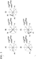
- Fig. 3 is a diagram for explaining an example of a position of the operation unit 11D (specifically, positions P1 to P9 of the tip end portion of the lever of the joystick) in the ship 1 of the first embodiment.
- the lever of the operation unit 11D (the joystick) is not tilted. Therefore, the operation unit 11D (specifically, the tip end portion of the lever of the joystick) is located at the position (a neutral position) P1. In a case in which the operation unit 11D (the tip end portion of the lever of the joystick) is located at the position P1, the control device 14 for an outboard motor does not cause the steering actuators 12A2 and 13A2 and the propulsion units 12A1 and 13A1 to generate a propulsion force for the ship 1.
- the position P1 is a position at which the outboard motors 12 and 13 do not generate the propulsion force for the ship 1.
- the lever of the joystick is tilted in a rightward direction. Therefore, the tip end portion of the lever of the joystick is located at the position P2 on a rightward side from the position P1.
- the control device 14 for an outboard motor causes the steering actuators 12A2 and 13A2 and the propulsion units 12A1 and 13A1 to generate a propulsion force for moving the ship 1 in the rightward direction.
- the position P2 is a position at which the outboard motors 12 and 13 generate a propulsion force for moving the ship 1 in the rightward direction (specifically, translational movement).
- the lever of the joystick is tilted in a rightward-forward direction. Therefore, the tip end portion of the lever of the joystick is located at the position P3 on a rightward-forward side from the position P1.
- the control device 14 for an outboard motor causes the steering actuators 12A2 and 13A2 and the propulsion units 12A1 and 13A1 to generate a propulsion force for moving the ship 1 in the rightward-forward direction forming an acute angle ⁇ 3 with a leftward-rightward direction.
- the position P3 is a position at which the outboard motors 12 and 13 generate a propulsion force for moving the ship 1 in the rightward-forward direction (translational movement).
- the lever of the joystick is tilted in a rightward-backward direction. Therefore, the tip end portion of the lever of the joystick is located at the position P4 on a rightward-backward side from the position P1.
- the control device 14 for an outboard motor causes the steering actuators 12A2 and 13A2 and the propulsion units 12A1 and 13A1 to generate a propulsion force for moving the ship 1 in the rightward-backward direction forming an acute angle ⁇ 4 with the leftward-rightward direction.
- the position P4 is a position at which the outboard motors 12 and 13 generate a propulsion force for moving the ship 1 in the rightward-backward direction (translational movement).
- the lever of the joystick is tilted in a leftward direction. Therefore, the tip end portion of the lever of the joystick is located at the position P5 on a leftward side from the position P1.
- the control device 14 for an outboard motor causes the steering actuators 12A2 and 13A2 and the propulsion units 12A1 and 13A1 to generate a propulsion force for moving the ship 1 in the leftward direction.
- the position P5 is a position at which the outboard motors 12 and 13 generate a propulsion force for moving the ship 1 in the leftward direction (translational movement).
- the lever of the joystick is tilted in a leftward-forward direction. Therefore, the tip end portion of the lever of the joystick is located at the position P6 on a leftward-forward side from the position P1.
- the control device 14 for an outboard motor causes the steering actuators 12A2 and 13A2 and the propulsion units 12A1 and 13A1 to generate a propulsion force for moving the ship 1 in the leftward-forward direction forming an acute angle ⁇ 6 with a leftward-rightward direction.
- the position P6 is a position at which the outboard motors 12 and 13 generate a propulsion force for moving the ship 1 in the leftward-forward direction (translational movement).
- the lever of the joystick is tilted in a leftward-backward direction. Therefore, the tip end portion of the lever of the joystick is located at the position P7 on a leftward-backward side from the position P1.
- the control device 14 for an outboard motor causes the steering actuators 12A2 and 13A2 and the propulsion units 12A1 and 13A1 to generate a propulsion force for moving the ship 1 in the leftward-backward direction forming an acute angle ⁇ 7 with the leftward-rightward direction.
- the position P7 is a position at which the outboard motors 12 and 13 generate a propulsion force for moving the ship 1 in the leftward-backward direction (translational movement).
- the lever of the joystick is tilted in a forward direction. Therefore, the tip end portion of the lever of the joystick is located at the position P8 on a front side from the position P1.
- the control device 14 for an outboard motor causes the steering actuators 12A2 and 13A2 and the propulsion units 12A1 and 13A1 to generate a propulsion force for moving the ship 1 in the forward direction.
- the position P8 is a position at which the outboard motors 12 and 13 generate a propulsion force for moving the ship 1 in the forward direction (forward movement).
- the lever of the joystick is tilted in a backward direction. Therefore, the tip end portion of the lever of the joystick is located at the position P9 on a backward side from the position P1.
- the control device 14 for an outboard motor causes the steering actuators 12A2 and 13A2 and the propulsion units 12A1 and 13A1 to generate a propulsion force for moving the ship 1 in the backward direction.
- the position P9 is a position at which the outboard motors 12 and 13 generate a propulsion force for moving the ship 1 in the backward direction (backward movement).
- the tip end portion of the lever of the joystick having an automatic return function is located at the position P1.
- the tip end portion of the lever of the joystick can be located at, for example, a position such as the positions P1 to P9 according to the operation of the ship operator.
- Figs. 4 and 5 are diagrams for explaining an example of a movement route of the operation unit 11D (specifically, a movement route of the tip end portion of the lever of the joystick) in the ship 1 of the first embodiment.
- the operation unit 11D (specifically, the tip end portion of the lever of the joystick) is moved from the position P1 to the position P2.
- the movement route calculation unit 14A calculates a movement route P1 ⁇ P2 of the tip end portion of the lever of the joystick based on the position of the lever when the tip end portion of the lever of the joystick is located at the position P1 and the position of the lever when the tip end portion of the lever of the joystick is located at the position P2.
- the propulsion force calculation unit 14B calculates the propulsion force which the outboard motors 12 and 13 generate based on the movement route P1 ⁇ P2 of the tip end portion of the lever of the joystick which is calculated by the movement route calculation unit 14A. Specifically, the propulsion force calculation unit 14B calculates the magnitude of the propulsion force for moving the ship 1 in the rightward direction.
- the control device 14 for an outboard motor causes the steering actuators 12A2 and 13A2 and the propulsion units 12A1 and 13A1 to generate the propulsion force in the rightward direction which has the magnitude calculated by the propulsion force calculation unit 14B.
- the ship operator may want to move the ship 1 in the rightward-forward direction (translational movement).
- the operation unit 11D (the tip end portion of the lever of the joystick) is moved from the position P1 to the position P3.
- the movement route calculation unit 14A calculates a movement route P1 ⁇ P3 of the tip end portion of the lever of the joystick based on the position of the lever when the tip end portion of the lever of the joystick is located at the position P1 and the position of the lever when the tip end portion of the lever of the joystick is located at the position P3.
- the propulsion force calculation unit 14B calculates the propulsion force which the outboard motors 12 and 13 generate based on the movement route P1 ⁇ P3 of the tip end portion of the lever of the joystick which is calculated by the movement route calculation unit 14A. Specifically, the propulsion force calculation unit 14B calculates the magnitude of the propulsion force for moving the ship 1 in the rightward-forward direction.
- the control device 14 for an outboard motor causes the steering actuators 12A2 and 13A2 and the propulsion units 12A1 and 13A1 to generate the propulsion force in the rightward-forward direction which has the magnitude calculated by the propulsion force calculation unit 14B.
- the ship 1 may receive a force in a backward direction due to, for example, wind, tidal current, and the like.
- the operation unit 11D (the tip end portion of the lever of the joystick) is moved from the position P1 to the position P2. Since the ship 1 is likely to be swept in the backward direction by the force in the backward direction due to wind, tidal current, and the like, the operation unit 11D (the tip end portion of lever of the joystick) is then moved from the position P2 to the position P3.
- the operation unit 11D (the tip end portion of the lever of the joystick) is moved from the position P1 to the position P3 via the position P2.
- the movement route calculation unit 14A calculates a movement route P1 ⁇ P2 ⁇ P3 of the tip end portion of the lever of the joystick based on the position of the lever when the tip end portion of the lever of the joystick is located at the position P1, the position of the lever when the tip end portion of the lever of the joystick is located at the position P2, and the position of the lever when the tip end portion of the lever of the joystick is located at the position P3.
- the propulsion force calculation unit 14B calculates the propulsion force which the outboard motors 12 and 13 generate based on the movement route P1 ⁇ P2 ⁇ P3 of the tip end portion of the lever of the joystick which is calculated by the movement route calculation unit 14A. Specifically, the propulsion force calculation unit 14B calculates the magnitude of the propulsion force (that is, the propulsion force in the rightward-forward direction) for moving the ship 1 in the rightward direction against the force in the backward direction due to, for example, wind, tidal current, and the like.
- the control device 14 for an outboard motor causes the steering actuators 12A2 and 13A2 and the propulsion units 12A1 and 13A1 to generate the propulsion force in the rightward-forward direction which has the magnitude calculated by the propulsion force calculation unit 14B.
- the ship 1 may be swept in the backward direction without being moved in the rightward direction (translational movement) as desired by the ship operator.
- the control device 14 for an outboard motor causes the steering actuators 12A2 and 13A2 and the propulsion units 12A1 and 13A1 to generate the propulsion force in the rightward-forward direction which has the forward-backward direction component (specifically, a forward direction component) larger than that in the example shown in (B) of Fig. 4 .
- the ship 1 moves in the rightward direction (translational movement) according to the desire of the ship operator and against the force in the backward direction due to, for example, wind, tidal current, and the like.
- Fig. 6 is a diagram showing a propulsion force in a rightward-forward direction which the control device 14 for an outboard motor causes the outboard motors 12 and 13 to generate in the example shown in (B) of Fig. 4 , a propulsion force in a rightward-forward direction which the control device 14 for an outboard motor causes the outboard motors 12 and 13 to generate in the example shown in (C) of Fig. 4 , and the like for comparison.
- the magnitude of the leftward-rightward direction component F11R of the propulsion force F11 in the rightward-forward direction and the magnitude of the leftward-rightward direction component F12R of the propulsion force F12 in the rightward-forward direction are set to be equal to each other.
- the forward-backward direction component F12F of the propulsion force F12 in the rightward-forward direction is set to be larger than the forward-backward direction component F11F of the propulsion force F11 in the rightward-forward direction.
- the propulsion force F12 in the rightward-forward direction is also larger than the propulsion force F11 in the rightward-forward direction.
- the magnitude of the leftward-rightward direction component F11R of the propulsion force F11 in the rightward-forward direction and the magnitude of the leftward-rightward direction component F12R of the propulsion force F12 in the rightward-forward direction are set to be equal to each other. Further, the forward-backward direction component F12F of the propulsion force F12 in the rightward-forward direction is set to be larger than the forward-backward direction component F11F of the propulsion force F11 in the rightward-forward direction.
- the magnitude of the forward-backward direction component F12F of the propulsion force F12 in the rightward-forward direction and the magnitude of the forward-backward direction component F11F of the propulsion force F11 in the rightward-forward direction are set to be equal to each other, and the leftward-rightward direction component F12R of the propulsion force F12 in the rightward-forward direction is set smaller than the leftward-rightward direction component F11R of the propulsion force F11 in the rightward-forward direction. That is, in this example, the propulsion force F12 in the rightward-forward direction is smaller than the propulsion force F11 in the rightward-forward direction.
- the ship operator may switch (correct) the direction of the ship 1 moving in the rightward direction (translational movement) from the rightward direction to the rightward-forward direction.
- the operation unit 11D (the tip end portion of the lever of the joystick) is moved from the position P1 to the position P2.
- the operation unit 11D (the tip end portion of the lever of the joystick) is then moved from the position P2 to the position P3.
- the operation unit 11D (the tip end portion of the lever of the joystick) is moved from the position P1 to the position P3 via the position P2.
- the movement route calculation unit 14A calculates a movement route P1 ⁇ P2 ⁇ P3 of the tip end portion of the lever of the joystick based on the position of the lever when the tip end portion of the lever of the joystick is located at the position P1, the position of the lever when the tip end portion of the lever of the joystick is located at the position P2, and the position of the lever when the tip end portion of the lever of the joystick is located at the position P3.
- the propulsion force calculation unit 14B calculates the propulsion force which the outboard motors 12 and 13 generate based on the movement route P1 ⁇ P2 ⁇ P3 of the tip end portion of the lever of the joystick which is calculated by the movement route calculation unit 14A. Specifically, the propulsion force calculation unit 14B calculates the magnitude of the propulsion force for switching the direction of the ship 1 moving in the rightward direction from the rightward direction to the rightward-forward direction (that is, the propulsion force in the rightward-forward direction).
- the control device 14 for an outboard motor causes the steering actuators 12A2 and 13A2 and the propulsion units 12A1 and 13A1 to generate the propulsion force in the rightward-forward direction which has the magnitude calculated by the propulsion force calculation unit 14B.
- the ship operator may feel that a response operation of the ship 1 to the correction operation of the ship operator is slow (that is, the switching of the direction of the ship 1 from the rightward direction to the rightward-forward direction is slow).
- the control device 14 for an outboard motor causes the steering actuators 12A2 and 13A2 and the propulsion units 12A1 and 13A1 to generate the propulsion force F12 in the rightward-forward direction in which the forward-backward direction component is larger than that in the example shown in (B) of Fig. 4 (specifically, the forward direction component F12F is larger than the forward direction component F11F).
- the direction of the ship 1 can be quickly switched from the rightward direction to the rightward-forward direction according to the desire of the ship operator.
- control device 14 for an outboard motor causes the steering actuators 12A2 and 13A2 and the propulsion units 12A1 and 13A1 to generate the propulsion force F12 in the rightward-forward direction in which the leftward-rightward direction component is smaller than that in the example shown in (B) of Fig. 4 (specifically, the forward direction component F12F and the forward direction component F11F are equal to each other, and the rightward direction component F12R is smaller than the rightward direction component F11R).
- the direction of the ship 1 can be quickly switched from the rightward direction to the rightward-forward direction according to the desire of the ship operator.
- the ship operator may want to move the ship 1 in the rightward-backward direction (translational movement).
- the movement route calculation unit 14A calculates a movement route P1 ⁇ P4 of the tip end portion of the lever of the joystick based on the position of the lever when the tip end portion of the lever of the joystick is located at the position P1 and the position of the lever when the tip end portion of the lever of the joystick is located at the position P4.
- the propulsion force calculation unit 14B calculates the propulsion force which the outboard motors 12 and 13 generate based on the movement route P1 ⁇ P4 of the tip end portion of the lever of the joystick which is calculated by the movement route calculation unit 14A. Specifically, the propulsion force calculation unit 14B calculates the magnitude of the propulsion force for moving the ship 1 in the rightward-backward direction.
- the control device 14 for an outboard motor causes the steering actuators 12A2 and 13A2 and the propulsion units 12A1 and 13A1 to generate the propulsion force in the rightward-backward direction which has the magnitude calculated by the propulsion force calculation unit 14B.
- the ship 1 may receive a force in a forward direction due to, for example, wind, tidal current, and the like.
- the operation unit 11D (the tip end portion of the lever of the joystick) is moved from the position P1 to the position P2. Since the ship 1 is likely to be swept in the forward direction by the force in the forward direction due to wind, tidal current, and the like, the operation unit 11D (the tip end portion of lever of the joystick) is then moved from the position P2 to the position P4.
- the operation unit 11D (the tip end portion of the lever of the joystick) is moved from the position P1 to the position P4 via the position P2.
- the movement route calculation unit 14A calculates a movement route P1 ⁇ P2 ⁇ P4 of the tip end portion of the lever of the joystick based on the position of the lever when the tip end portion of the lever of the joystick is located at the position P1, the position of the lever when the tip end portion of the lever of the joystick is located at the position P2, and the position of the lever when the tip end portion of the lever of the joystick is located at the position P4.
- the propulsion force calculation unit 14B calculates the propulsion force which the outboard motors 12 and 13 generate based on the movement route P1 ⁇ P2 ⁇ P4 of the tip end portion of the lever of the joystick which is calculated by the movement route calculation unit 14A. Specifically, the propulsion force calculation unit 14B calculates the magnitude of the propulsion force (that is, the propulsion force in the rightward-backward direction) for moving the ship 1 in the rightward direction against the force in the forward direction due to, for example, wind, tidal current, and the like.
- the control device 14 for an outboard motor causes the steering actuators 12A2 and 13A2 and the propulsion units 12A1 and 13A1 to generate the propulsion force in the rightward-backward direction which has the magnitude calculated by the propulsion force calculation unit 14B.
- the control device 14 for an outboard motor causes the steering actuators 12A2 and 13A2 and the propulsion units 12A1 and 13A1 to generate the propulsion force in the rightward-backward direction which has the forward-backward direction component (specifically, a backward direction component) larger than that in the example shown in (D) of Fig. 4 .
- the ship 1 moves in the rightward direction (translational movement) according to the desire of the ship operator and against the force in the forward direction due to, for example, wind, tidal current, and the like.
- FIG. 6 shows a propulsion force F21 in a rightward-backward direction which the control device 14 for an outboard motor causes the outboard motors 12 and 13 to generate (that is, which is calculated by the propulsion force calculation unit 14B), a forward-backward direction component F21B thereof, and a leftward-rightward direction component F21R thereof in a case in which the operation unit 11D (the tip end portion of the lever of the joystick) is moved directly from the position P1 to the position P4 (in the example shown in (D) of Fig. 4 ).
- the operation unit 11D the tip end portion of the lever of the joystick
- FIG. 6 shows a propulsion force F22 in a rightward-backward direction which the control device 14 for an outboard motor causes the outboard motors 12 and 13 to generate (that is, which is calculated by the propulsion force calculation unit 14B), a forward-backward direction component F22B thereof, and a leftward-rightward direction component F22R thereof in a case in which the operation unit 11D (the tip end portion of the lever of the joystick) is moved from the position P1 to the position P4 via the position P2 (in the example shown in (E) of Fig. 4 ).
- the operation unit 11D the tip end portion of the lever of the joystick
- the magnitude of the leftward-rightward direction component F21R of the propulsion force F21 in the rightward-backward direction and the magnitude of the leftward-rightward direction component F22R of the propulsion force F22 in the rightward-backward direction are set to be equal to each other.
- the forward-backward direction component F22B of the propulsion force F22 in the rightward-backward direction is set to be larger than the forward-backward direction component F21B of the propulsion force F21 in the rightward-backward direction.
- the propulsion force F22 in the rightward-backward direction is also larger than the propulsion force F21 in the rightward-backward direction.
- the magnitude of the leftward-rightward direction component F21R of the propulsion force F21 in the rightward-backward direction and the magnitude of the leftward-rightward direction component F22R of the propulsion force F22 in the rightward-backward direction are set to be equal to each other.
- the forward-backward direction component F22B of the propulsion force F22 in the rightward-backward direction is set to be larger than the forward-backward direction component F21B of the propulsion force F21 in the rightward-backward direction.
- the magnitude of the forward-backward direction component F22B of the propulsion force F22 in the rightward-backward direction and the magnitude of the forward-backward direction component F21B of the propulsion force F21 in the rightward-backward direction are set to be equal to each other, and the leftward-rightward direction component F22R of the propulsion force F22 in the rightward-backward direction is set smaller than the leftward-rightward direction component F21R of the propulsion force F21 in the rightward-backward direction. That is, in this example, the propulsion force F22 in the rightward-backward direction is smaller than the propulsion force F21 in the rightward-backward direction.
- the ship operator may switch (correct) the direction of the ship 1 moving in the rightward direction (translational movement) from the rightward direction to the rightward-backward direction.
- the operation unit 11D (the tip end portion of the lever of the joystick) is moved from the position P1 to the position P2.
- the operation unit 11D (the tip end portion of the lever of the joystick) is then moved from the position P2 to the position P4.
- the operation unit 11D (the tip end portion of the lever of the joystick) is moved from the position P1 to the position P4 via the position P2.
- the movement route calculation unit 14A calculates a movement route P1 ⁇ P2 ⁇ P4 of the tip end portion of the lever of the joystick based on the position of the lever when the tip end portion of the lever of the joystick is located at the position P1, the position of the lever when the tip end portion of the lever of the joystick is located at the position P2, and the position of the lever when the tip end portion of the lever of the joystick is located at the position P4.
- the propulsion force calculation unit 14B calculates the propulsion force which the outboard motors 12 and 13 generate based on the movement route P1 ⁇ P2 ⁇ P4 of the tip end portion of the lever of the joystick which is calculated by the movement route calculation unit 14A. Specifically, the propulsion force calculation unit 14B calculates the magnitude of the propulsion force for switching the direction of the ship 1 moving in the rightward direction from the rightward direction to the rightward-backward direction (that is, the propulsion force in the rightward-backward direction).
- the control device 14 for an outboard motor causes the steering actuators 12A2 and 13A2 and the propulsion units 12A1 and 13A1 to generate the propulsion force in the rightward-backward direction which has the magnitude calculated by the propulsion force calculation unit 14B.
- the control device 14 for an outboard motor causes the steering actuators 12A2 and 13A2 and the propulsion units 12A1 and 13A1 to generate the propulsion force F22 in the rightward-backward direction in which the forward-backward direction component is larger than that in the example shown in (D) of Fig. 4 (specifically, the backward direction component F22B is larger than the backward direction component F21B).
- the direction of the ship 1 can be quickly switched from the rightward direction to the rightward-backward direction according to the desire of the ship operator.
- control device 14 for an outboard motor causes the steering actuators 12A2 and 13A2 and the propulsion units 12A1 and 13A1 to generate the propulsion force F22 in the rightward-backward direction in which the leftward-rightward direction component is smaller than that in the example shown in (D) of Fig. 4 (specifically, the backward direction component F22B and the backward direction component F21B are equal to each other, and the rightward direction component F22R is smaller than the rightward direction component F21R).
- the direction of the ship 1 can be quickly switched from the rightward direction to the rightward-backward direction according to the desire of the ship operator.
- the ship operator may want to move the ship 1 in the leftward direction (translational movement).
- the operation unit 11D (specifically, the tip end portion of the lever of the joystick) is moved from the position P1 to the position P5.
- the movement route calculation unit 14A calculates a movement route P1 ⁇ P5 of the tip end portion of the lever of the joystick based on the position of the lever when the tip end portion of the lever of the joystick is located at the position P1 and the position of the lever when the tip end portion of the lever of the joystick is located at the position P5.
- the propulsion force calculation unit 14B calculates the propulsion force which the outboard motors 12 and 13 generate based on the movement route P1 ⁇ P5 of the tip end portion of the lever of the joystick which is calculated by the movement route calculation unit 14A. Specifically, the propulsion force calculation unit 14B calculates the magnitude of the propulsion force for moving the ship 1 in the leftward direction.
- the control device 14 for an outboard motor causes the steering actuators 12A2 and 13A2 and the propulsion units 12A1 and 13A1 to generate the propulsion force in the leftward direction which has the magnitude calculated by the propulsion force calculation unit 14B.
- the ship operator may want to move the ship 1 in the leftward-forward direction (translational movement).
- the operation unit 11D (the tip end portion of the lever of the joystick) is moved from the position P1 to the position P6.
- the movement route calculation unit 14A calculates a movement route P1 ⁇ P6 of the tip end portion of the lever of the joystick based on the position of the lever when the tip end portion of the lever of the joystick is located at the position P1 and the position of the lever when the tip end portion of the lever of the joystick is located at the position P6.
- the propulsion force calculation unit 14B calculates the propulsion force which the outboard motors 12 and 13 generate based on the movement route P1 ⁇ P6 of the tip end portion of the lever of the joystick which is calculated by the movement route calculation unit 14A. Specifically, the propulsion force calculation unit 14B calculates the magnitude of the propulsion force for moving the ship 1 in the leftward-forward direction.
- the control device 14 for an outboard motor causes the steering actuators 12A2 and 13A2 and the propulsion units 12A1 and 13A1 to generate the propulsion force in the leftward-forward direction which has the magnitude calculated by the propulsion force calculation unit 14B.
- the ship 1 moves in the leftward-forward direction (translational movement).
- the ship 1 may receive a force in a backward direction due to, for example, wind, tidal current, and the like.
- the operation unit 11D (the tip end portion of the lever of the joystick) is moved from the position P1 to the position P5. Since the ship 1 is likely to be swept in the backward direction by the force in the backward direction due to wind, tidal current, and the like, the operation unit 11D (the tip end portion of lever of the joystick) is then moved from the position P5 to the position P6.
- the operation unit 11D (the tip end portion of the lever of the joystick) is moved from the position P1 to the position P6 via the position P5.
- the movement route calculation unit 14A calculates a movement route P1 ⁇ P5 ⁇ P6 of the tip end portion of the lever of the joystick based on the position of the lever when the tip end portion of the lever of the joystick is located at the position P1, the position of the lever when the tip end portion of the lever of the joystick is located at the position P5, and the position of the lever when the tip end portion of the lever of the joystick is located at the position P6.
- the propulsion force calculation unit 14B calculates the propulsion force which the outboard motors 12 and 13 generate based on the movement route P1 ⁇ P5 ⁇ P6 of the tip end portion of the lever of the joystick which is calculated by the movement route calculation unit 14A. Specifically, the propulsion force calculation unit 14B calculates the magnitude of the propulsion force (that is, the propulsion force in the leftward-forward direction) for moving the ship 1 in the leftward direction against the force in the backward direction due to, for example, wind, tidal current, and the like.
- the control device 14 for an outboard motor causes the steering actuators 12A2 and 13A2 and the propulsion units 12A1 and 13A1 to generate the propulsion force in the leftward-forward direction which has the magnitude calculated by the propulsion force calculation unit 14B.
- the control device 14 for an outboard motor causes the steering actuators 12A2 and 13A2 and the propulsion units 12A1 and 13A1 to generate the propulsion force in the leftward-forward direction which has the forward-backward direction component (specifically, a forward direction component) larger than that in the example shown in (B) of Fig. 5 .
- the ship 1 moves in the leftward direction (translational movement) according to the desire of the ship operator and against the force in the backward direction due to, for example, wind, tidal current, and the like.
- Fig. 7 is a diagram showing a propulsion force in a leftward-forward direction which the control device 14 for an outboard motor causes the outboard motors 12 and 13 to generate in the example shown in (B) of Fig. 5 , a propulsion force in a leftward-forward direction which the control device 14 for an outboard motor causes the outboard motors 12 and 13 to generate in the example shown in (C) of Fig. 5 , and the like for comparison.
- FIG. 7 shows a propulsion force F31 in a leftward-forward direction which the control device 14 for an outboard motor causes the outboard motors 12 and 13 to generate (that is, which is calculated by the propulsion force calculation unit 14B), a forward-backward direction component F31F thereof, and a leftward-rightward direction component F31L thereof in a case in which the operation unit 11D (the tip end portion of the lever of the joystick) is moved directly from the position P1 to the position P6 (in the example shown in (B) of Fig. 5 ).
- FIG. 7 shows a propulsion force F32 in a leftward-forward direction which the control device 14 for an outboard motor causes the outboard motors 12 and 13 to generate (that is, which is calculated by the propulsion force calculation unit 14B), a forward-backward direction component F32F thereof, and a leftward-rightward direction component F32L thereof in a case in which the operation unit 11D (the tip end portion of the lever of the joystick) is moved from the position P1 to the position P6 via the position P5 (in the example shown in (C) of Fig. 5 ).
- the operation unit 11D the tip end portion of the lever of the joystick
- the magnitude of the leftward-rightward direction component F31L of the propulsion force F31 in the leftward-forward direction and the magnitude of the leftward-rightward direction component F32L of the propulsion force F32 in the leftward-forward direction are set to be equal to each other.
- the forward-backward direction component F32F of the propulsion force F32 in the leftward-forward direction is set to be larger than the forward-backward direction component F31F of the propulsion force F31 in the leftward-forward direction.
- the propulsion force F32 in the leftward-forward direction is also larger than the propulsion force F31 in the leftward-forward direction.
- the magnitude of the leftward-rightward direction component F31L of the propulsion force F31 in the leftward-forward direction and the magnitude of the leftward-rightward direction component F32L of the propulsion force F32 in the leftward-forward direction are set to be equal to each other. Further, the forward-backward direction component F32F of the propulsion force F32 in the leftward-forward direction is set to be larger than the forward-backward direction component F31F of the propulsion force F31 in the leftward-forward direction.
- the magnitude of the forward-backward direction component F32F of the propulsion force F32 in the leftward-forward direction and the magnitude of the forward-backward direction component F31F of the propulsion force F31 in the leftward-forward direction are set to be equal to each other, and the leftward-rightward direction component F32L of the propulsion force F32 in the leftward-forward direction is set smaller than the leftward-rightward direction component F31L of the propulsion force F31 in the leftward-forward direction. That is, in this example, the propulsion force F32 in the leftward-forward direction is smaller than the propulsion force F31 in the leftward-forward direction.
- the ship operator may switch (correct) the direction of the ship 1 moving in the leftward direction (translational movement) from the leftward direction to the leftward-forward direction.
- the operation unit 11D (the tip end portion of the lever of the joystick) is moved from the position P1 to the position P5.
- the operation unit 11D (the tip end portion of the lever of the joystick) is then moved from the position P5 to the position P6.
- the operation unit 11D (the tip end portion of the lever of the joystick) is moved from the position P1 to the position P6 via the position P5.
- the movement route calculation unit 14A calculates a movement route P1 ⁇ P5 ⁇ P6 of the tip end portion of the lever of the joystick based on the position of the lever when the tip end portion of the lever of the joystick is located at the position P1, the position of the lever when the tip end portion of the lever of the joystick is located at the position P5, and the position of the lever when the tip end portion of the lever of the joystick is located at the position P6.
- the propulsion force calculation unit 14B calculates the propulsion force which the outboard motors 12 and 13 generate based on the movement route P1 ⁇ P5 ⁇ P6 of the tip end portion of the lever of the joystick which is calculated by the movement route calculation unit 14A. Specifically, the propulsion force calculation unit 14B calculates the magnitude of the propulsion force for switching the direction of the ship 1 moving in the leftward direction from the leftward direction to the leftward-forward direction (that is, the propulsion force in the leftward-forward direction).
- the control device 14 for an outboard motor causes the steering actuators 12A2 and 13A2 and the propulsion units 12A1 and 13A1 to generate the propulsion force in the leftward-forward direction which has the magnitude calculated by the propulsion force calculation unit 14B.
- the control device 14 for an outboard motor causes the steering actuators 12A2 and 13A2 and the propulsion units 12A1 and 13A1 to generate the propulsion force F32 in the leftward-forward direction in which the forward-backward direction component is larger than that in the example shown in (B) of Fig. 5 (specifically, the forward direction component F32F is larger than the forward direction component F31F).
- the direction of the ship 1 can be quickly switched from the leftward direction to the leftward-forward direction according to the desire of the ship operator.
- control device 14 for an outboard motor causes the steering actuators 12A2 and 13A2 and the propulsion units 12A1 and 13A1 to generate the propulsion force F32 in the leftward-forward direction in which the leftward-rightward direction component is smaller than that in the example shown in (B) of Fig. 5 (specifically, the forward direction component F32F and the forward direction component F31F are equal to each other, and the leftward direction component F32L is smaller than the leftward direction component F31L).
- the direction of the ship 1 can be quickly switched from the leftward direction to the leftward-forward direction according to the desire of the ship operator.
- the ship operator may want to move the ship 1 in the leftward-backward direction (translational movement).
- the operation unit 11D (the tip end portion of the lever of the joystick) is moved from the position P1 to the position P7.
- the movement route calculation unit 14A calculates a movement route P1 ⁇ P7 of the tip end portion of the lever of the joystick based on the position of the lever when the tip end portion of the lever of the joystick is located at the position P1 and the position of the lever when the tip end portion of the lever of the joystick is located at the position P7.
- the propulsion force calculation unit 14B calculates the propulsion force which the outboard motors 12 and 13 generate based on the movement route P1 ⁇ P7 of the tip end portion of the lever of the joystick which is calculated by the movement route calculation unit 14A. Specifically, the propulsion force calculation unit 14B calculates the magnitude of the propulsion force for moving the ship 1 in the leftward-backward direction.
- the control device 14 for an outboard motor causes the steering actuators 12A2 and 13A2 and the propulsion units 12A1 and 13A1 to generate the propulsion force in the leftward-backward direction which has the magnitude calculated by the propulsion force calculation unit 14B.
- the ship 1 may receive a force in a forward direction due to, for example, wind, tidal current, and the like.
- the operation unit 11D (the tip end portion of the lever of the joystick) is moved from the position P1 to the position P5. Since the ship 1 is likely to be swept in the forward direction by the force in the forward direction due to wind, tidal current, and the like, the operation unit 11D (the tip end portion of lever of the joystick) is then moved from the position P5 to the position P7.
- the operation unit 11D (the tip end portion of the lever of the joystick) is moved from the position P1 to the position P7 via the position P5.
- the movement route calculation unit 14A calculates a movement route P1 ⁇ P5 ⁇ P7 of the tip end portion of the lever of the joystick based on the position of the lever when the tip end portion of the lever of the joystick is located at the position P1, the position of the lever when the tip end portion of the lever of the joystick is located at the position P5, and the position of the lever when the tip end portion of the lever of the joystick is located at the position P7.
- the propulsion force calculation unit 14B calculates the propulsion force which the outboard motors 12 and 13 generate based on the movement route P1 ⁇ P5 ⁇ P7 of the tip end portion of the lever of the joystick which is calculated by the movement route calculation unit 14A. Specifically, the propulsion force calculation unit 14B calculates the magnitude of the propulsion force (that is, the propulsion force in the leftward-backward direction) for moving the ship 1 in the leftward direction against the force in the forward direction due to, for example, wind, tidal current, and the like.
- the control device 14 for an outboard motor causes the steering actuators 12A2 and 13A2 and the propulsion units 12A1 and 13A1 to generate the propulsion force in the leftward-backward direction which has the magnitude calculated by the propulsion force calculation unit 14B.
- the control device 14 for an outboard motor causes the steering actuators 12A2 and 13A2 and the propulsion units 12A1 and 13A1 to generate the propulsion force in the leftward-backward direction which has the forward-backward direction component (specifically, a backward direction component) larger than that in the example shown in (D) of Fig. 5 .
- the ship 1 moves in the leftward direction (translational movement) according to the desire of the ship operator and against the force in the forward direction due to, for example, wind, tidal current, and the like.
- FIG. 7 shows a propulsion force F41 in a leftward-backward direction which the control device 14 for an outboard motor causes the outboard motors 12 and 13 to generate (that is, which is calculated by the propulsion force calculation unit 14B), a forward-backward direction component F41B thereof, and a leftward-rightward direction component F41L thereof in a case in which the operation unit 11D (the tip end portion of the lever of the joystick) is moved directly from the position P1 to the position P7 (in the example shown in (D) of Fig. 5 ).
- the operation unit 11D the tip end portion of the lever of the joystick
- FIG. 7 shows a propulsion force F42 in a leftward-backward direction which the control device 14 for an outboard motor causes the outboard motors 12 and 13 to generate (that is, which is calculated by the propulsion force calculation unit 14B), a forward-backward direction component F42B thereof, and a leftward-rightward direction component F42L thereof in a case in which the operation unit 11D (the tip end portion of the lever of the joystick) is moved from the position P1 to the position P7 via the position P5 (in the example shown in (E) of Fig. 5 ).
- the operation unit 11D the tip end portion of the lever of the joystick
- the magnitude of the leftward-rightward direction component F41L of the propulsion force F41 in the leftward-backward direction and the magnitude of the leftward-rightward direction component F42L of the propulsion force F42 in the leftward-backward direction are set to be equal to each other.
- the forward-backward direction component F42B of the propulsion force F42 in the leftward-backward direction is set to be larger than the forward-backward direction component F41B of the propulsion force F41 in the leftward-backward direction.
- the propulsion force F42 in the leftward-backward direction is also larger than the propulsion force F41 in the leftward-backward direction.
- the magnitude of the leftward-rightward direction component F41L of the propulsion force F41 in the leftward-backward direction and the magnitude of the leftward-rightward direction component F42L of the propulsion force F42 in the leftward-backward direction are set to be equal to each other.
- the forward-backward direction component F42B of the propulsion force F42 in the leftward-backward direction is set to be larger than the forward-backward direction component F41B of the propulsion force F41 in the leftward-backward direction.
- the magnitude of the forward-backward direction component F42B of the propulsion force F42 in the leftward-backward direction and the magnitude of the forward-backward direction component F41B of the propulsion force F41 in the leftward-backward direction are set to be equal to each other, and the leftward-rightward direction component F42L of the propulsion force F42 in the leftward-backward direction is set smaller than the leftward-rightward direction component F41L of the propulsion force F41 in the leftward-backward direction. That is, in this example, the propulsion force F42 in the leftward-backward direction is smaller than the propulsion force F41 in the leftward-backward direction.
- the ship operator may switch (correct) the direction of the ship 1 moving in the leftward direction (translational movement) from the leftward direction to the leftward-backward direction.
- the operation unit 11D (the tip end portion of the lever of the joystick) is moved from the position P1 to the position P5.
- the operation unit 11D (the tip end portion of the lever of the joystick) is then moved from the position P5 to the position P7.
- the operation unit 11D (the tip end portion of the lever of the joystick) is moved from the position P1 to the position P7 via the position P5.
- the movement route calculation unit 14A calculates a movement route P1 ⁇ P5 ⁇ P7 of the tip end portion of the lever of the joystick based on the position of the lever when the tip end portion of the lever of the joystick is located at the position P1, the position of the lever when the tip end portion of the lever of the joystick is located at the position P5, and the position of the lever when the tip end portion of the lever of the joystick is located at the position P7.
- the propulsion force calculation unit 14B calculates the propulsion force which the outboard motors 12 and 13 generate based on the movement route P1 ⁇ P5 ⁇ P7 of the tip end portion of the lever of the joystick which is calculated by the movement route calculation unit 14A. Specifically, the propulsion force calculation unit 14B calculates the magnitude of the propulsion force for switching the direction of the ship 1 moving in the leftward direction from the leftward direction to the leftward-backward direction (that is, the propulsion force in the leftward-backward direction).
- the control device 14 for an outboard motor causes the steering actuators 12A2 and 13A2 and the propulsion units 12A1 and 13A1 to generate the propulsion force in the leftward-backward direction which has the magnitude calculated by the propulsion force calculation unit 14B.
- the control device 14 for an outboard motor causes the steering actuators 12A2 and 13A2 and the propulsion units 12A1 and 13A1 to generate the propulsion force F42 in the leftward-backward direction in which the forward-backward direction component is larger than that in the example shown in (D) of Fig. 5 (specifically, the backward direction component F42B is larger than the backward direction component F41B).
- the direction of the ship 1 can be quickly switched from the leftward direction to the leftward-backward direction according to the desire of the ship operator.
- control device 14 for an outboard motor causes the steering actuators 12A2 and 13A2 and the propulsion units 12A1 and 13A1 to generate the propulsion force F42 in the leftward-backward direction in which the leftward-rightward direction component is smaller than that in the example shown in (D) of Fig. 5 (specifically, the backward direction component F42B and the backward direction component F41B are equal to each other, and the leftward direction component F42L is smaller than the leftward direction component F41L).
- the direction of the ship 1 can be quickly switched from the leftward direction to the leftward-backward direction according to the desire of the ship operator.
- Fig. 8 is a flowchart for explaining an example of processing executed by the control device 14 for an outboard motor of the first embodiment.
- the processing shown in Fig. 8 starts in a case in which the operation unit 11D (the joystick) receives an input operation for operating the steering actuators 12A2 and 13A2 and the propulsion units 12A1 and 13A1 of the outboard motors 12 and 13.
- the operation unit 11D the joystick
- step S10 the control device 14 for an outboard motor acquires the position of the operation unit 11D (the position of the lever of the joystick) detected by, for example, a sensor such as a micro switch.
- step S20 the movement route calculation unit 14A of the control device 14 for an outboard motor calculates the movement route of the operation unit 11D (the movement route of the tip end portion of the lever of the joystick) based on a plurality of positions of the operation unit 11D (a plurality of positions of the lever of the joystick) acquired in step S 10.
- step S30 the propulsion force calculation unit 14B of the control device 14 for an outboard motor calculates the propulsion force which the steering actuators 12A2 and 13A2 and the propulsion units 12A1 and 13A1 generate based on the movement route of the operation unit 11D (the movement route of the tip end portion of the lever of the joystick) which is calculated in step S20.
- step S40 the control device 14 for an outboard motor controls the steering actuators 12A2 and 13A2 and the propulsion units 12A1 and 13A1 of the outboard motors 12 and 13 such that the steering actuators 12A2 and 13A2 and the propulsion units 12A1 and 13A1 of the outboard motors 12 and 13 generate the propulsion force calculated in step S20.
- step S20 in a case in which the movement route calculation unit 14A calculates the movement route P1 ⁇ P3 (see (B) of Fig. 4 ) of the tip end portion of the lever of the joystick, in step S30, the propulsion force calculation unit 14B calculates the propulsion force F11 in the rightward-forward direction (see (A) of Fig. 6 ) which has the forward-backward direction component F11F (see (A) of Fig. 6 ) and the leftward-rightward direction component F11R (see (A) of Fig. 6 ), and next, in step S40, the control device 14 for an outboard motor causes the outboard motors 12 and 13 to generate the propulsion force F11 in the rightward-forward direction.
- step S20 in a case in which the movement route calculation unit 14A calculates the movement route P1 ⁇ P4 (see (D) of Fig. 4 ) of the tip end portion of the lever of the joystick, in step S30, the propulsion force calculation unit 14B calculates the propulsion force F21 in the rightward-backward direction (see (C) of Fig. 6 ) which has the forward-backward direction component F21B (see (C) of Fig. 6 ) and the leftward-rightward direction component F21R (see (C) of Fig. 6 ), and next, in step S40, the control device 14 for an outboard motor causes the outboard motors 12 and 13 to generate the propulsion force F21 in the rightward-backward direction.
- step S20 in a case in which the movement route calculation unit 14A calculates the movement route P1 ⁇ P6 (see (B) of Fig. 5 ) of the tip end portion of the lever of the joystick, in step S30, the propulsion force calculation unit 14B calculates the propulsion force F31 in the leftward-forward direction (see (A) of Fig. 7 ) which has the forward-backward direction component F31F (see (A) of Fig. 7 ) and the leftward-rightward direction component F31L (see (A) of Fig. 7 ), and next, in step S40, the control device 14 for an outboard motor causes the outboard motors 12 and 13 to generate the propulsion force F31 in the leftward-forward direction.
- step S20 in a case in which the movement route calculation unit 14A calculates the movement route P1 ⁇ P7 (see (D) of Fig. 5 ) of the tip end portion of the lever of the joystick, in step S30, the propulsion force calculation unit 14B calculates the propulsion force F41 in the leftward-backward direction (see (C) of Fig. 7 ) which has the forward-backward direction component F41B (see (C) of Fig. 7 ) and the leftward-rightward direction component F41L (see (C) of Fig. 7 ), and next, in step S40, the control device 14 for an outboard motor causes the outboard motors 12 and 13 to generate the propulsion force F41 in the leftward-backward direction.
- a ship 1 to which a control device 14 for an outboard motor of the second embodiment is applied has the same configuration as the ship 1 to which the control device 14 for an outboard motor of the first embodiment described above is applied, except for the points which will be described later. Therefore, according to the ship 1 of the second embodiment, the same effect as that of the ship 1 of the first embodiment described above can be obtained except for the points which will be described later.
- Fig. 9 is a diagram showing an example of a ship to which a control device 14 for an outboard motor of the second embodiment is applied.
- the operation unit 11D is constituted by a joystick having a lever.
- the operation unit 11D is constituted by a touch panel.
- the ship operator can operate the steering actuators 12A2 and 13A2 and the propulsion units 12A1 and 13A1, and also by operating the operation unit 11D (the touch panel), the ship operator can operate the steering actuators 12A2 and 13A2 and the propulsion units 12A1 and 13A1.
- the ship hull 11 may not include the steering device 11A, the remote control device 11B, and the remote control device 11C.
- control device 14 for an outboard motor controls the steering actuator 12A2 and the propulsion unit 12A1 of the outboard motor 12 and the steering actuator 13A2 and the propulsion unit 13A1 of the outboard motor 13 based on the input operation to the operation unit 11D.
- control device 14 for an outboard motor controls the magnitude and direction of the propulsion force for the ship 1 which is generated by the steering actuators 12A2 and 13A2 and the propulsion units 12A1 and 13A1 based on, for example, a flick input operation to the operation unit 11D (the touch panel).
- the ship operator slides a finger pressing the touch panel in a desired direction while the finger presses the touch panel, for example.
- the movement route calculation unit 14A calculates a movement route of the operation unit 11D. Specifically, the movement route calculation unit 14A calculates the movement route of the finger that the ship operator slides while the finger presses the touch panel.
- the propulsion force calculation unit 14B calculates the propulsion force which the outboard motors 12 and 13 generate based on the movement route of the operation unit 11D which is calculated by the movement route calculation unit 14A (the movement route of the finger that the ship operator slides while the finger presses the touch panel).
- the operation unit 11D is configured such that a flick input operation can be performed on the operation unit 11D (the touch panel) and the rotation input operation can be performed on the operation unit 11D (the touch panel).
- the ship operator performs the rotation input operation by, for example, sliding one finger in a circumferential direction while the finger presses the touch panel in a state in which the other finger is brought into contact with the touch panel and is fixed as a center point.
- the control device 14 for an outboard motor controls the steering actuators 12A2 and 13A2 and the propulsion units 12A1 and 13A1 such that the ship hull 11 turns to the right.
- the control device 14 for an outboard motor controls the steering actuators 12A2 and 13A2 and the propulsion units 12A1 and 13A1 such that the ship hull 11 turns to the left.
- the control device 14 for an outboard motor controls the steering actuators 12A2 and 13A2 and the propulsion units 12A1 and 13A1 such that the ship hull 11 moves in a direction that the finger of the ship operator is slid while maintaining its posture. That is, when ship operator performs a flick input operation on the operation unit 11D (the touch panel), the front portion of the ship hull 11 and the rear portion of the hull 11 are translated.
- the operation unit 11D In a case in which the ship operator does not perform a flick input operation on the operation unit 11D (the touch panel) (that is, in a case in which the finger of the ship operator is not in contact with the touch panel), the operation unit 11D is in the same state as the state shown in (A) of Fig. 3 .
- the control device 14 for an outboard motor does not cause the steering actuators 12A2 and 13A2 and the propulsion units 12A1 and 13A1 to generate the propulsion force for the ship 1.
- the ship operator slides the finger in the rightward direction while the finger presses the touch panel and maintains the state in which the touch panel is pressed by the finger.
- the operation unit 11D is in the same state as the state shown in (B) of Fig. 3 .
- the movement route calculation unit 14A calculates the movement route (a contact start position ⁇ a current position) of the operation unit 11D based on the contact start position of the finger of the ship operator and the current position of the finger of the ship operator.
- the propulsion force calculation unit 14B calculates the propulsion force which the outboard motors 12 and 13 generate based on the movement route (the contact start position ⁇ the current position) of the operation unit 11D which is calculated by the movement route calculation unit 14A. Specifically, the propulsion force calculation unit 14B calculates the magnitude of the propulsion force for moving the ship 1 in the rightward direction.
- the control device 14 for an outboard motor causes the steering actuators 12A2 and 13A2 and the propulsion units 12A1 and 13A1 to generate the propulsion force in the rightward direction which has the magnitude calculated by the propulsion force calculation unit 14B.
- the ship operator moves the ship 1 in the rightward-forward direction (translational movement).
- the ship operator slides the finger in the rightward-forward direction while the finger presses the touch panel and maintains the state in which the touch panel is pressed by the finger.
- the operation unit 11D is in the same state as the state shown in (C) of Fig. 3 .
- the movement route calculation unit 14A calculates the movement route (a contact start position ⁇ a current position) of the operation unit 11D based on the contact start position of the finger of the ship operator and the current position of the finger of the ship operator moved in the rightward-forward direction.
- the propulsion force calculation unit 14B calculates the propulsion force which the outboard motors 12 and 13 generate based on the movement route (the contact start position ⁇ the current position) of the operation unit 11D which is calculated by the movement route calculation unit 14A. Specifically, the propulsion force calculation unit 14B calculates the magnitude of the propulsion force for moving the ship 1 in the rightward-forward direction.
- the control device 14 for an outboard motor causes the steering actuators 12A2 and 13A2 and the propulsion units 12A1 and 13A1 to generate the propulsion force in the rightward-forward direction which has the magnitude calculated by the propulsion force calculation unit 14B.
- the ship 1 when the ship operator moves the ship 1 in the rightward direction (translational movement), the ship 1 receives a force in a backward direction due to, for example, wind, tidal current, and the like.
- the ship operator slides the finger in the rightward direction while the finger presses the touch panel and maintains the state in which the touch panel is pressed by the finger. Since the ship 1 is likely to be swept in the backward direction by the force in the backward direction due to wind, tidal current, and the like, next, the ship operator further slides the finger in the forward direction while the finger presses the touch panel and maintains the state in which the touch panel is pressed by the finger.
- the movement route calculation unit 14A calculates the movement route (a contact start position ⁇ a rightward direction movement end position ⁇ a forward direction movement end position) of the operation unit 11D based on the contact start position of the finger of the ship operator, the position of the finger of the ship operator moved in the rightward direction, and the position of the finger of the ship operator moved in the forward direction.
- the propulsion force calculation unit 14B calculates the propulsion force which the outboard motors 12 and 13 generate based on the movement route (the contact start position ⁇ a rightward direction movement end position ⁇ a forward direction movement end position) of the operation unit 11D which is calculated by the movement route calculation unit 14A. Specifically, the propulsion force calculation unit 14B calculates the magnitude of the propulsion force (that is, the propulsion force in the rightward-forward direction) for moving the ship 1 in the rightward direction against the force in the backward direction due to, for example, wind, tidal current, and the like.
- the control device 14 for an outboard motor causes the steering actuators 12A2 and 13A2 and the propulsion units 12A1 and 13A1 to generate the propulsion force in the rightward-forward direction which has the magnitude calculated by the propulsion force calculation unit 14B.
- control device 14 for an outboard motor causes the steering actuators 12A2 and 13A2 and the propulsion units 12A1 and 13A1 to generate the propulsion force in the rightward-forward direction which has the forward-backward direction component (specifically, a forward direction component) larger than that in the second example of the ship 1 of the second embodiment.
- the ship 1 moves in the rightward direction (translational movement) according to the desire of the ship operator and against the force in the backward direction due to, for example, wind, tidal current, and the like.
- the ship operator moves the ship 1 in the rightward-backward direction (translational movement).
- the ship operator slides the finger in the rightward-backward direction while the finger presses the touch panel and maintains the state in which the touch panel is pressed by the finger.
- the operation unit 11D is in the same state as the state shown in (D) of Fig. 3 .
- the ship 1 when the ship operator moves the ship 1 in the rightward direction (translational movement), the ship 1 receives a force in a forward direction due to, for example, wind, tidal current, and the like.
- the ship operator slides the finger in the rightward direction while the finger presses the touch panel and maintains the state in which the touch panel is pressed by the finger. Since the ship 1 is likely to be swept in the forward direction by the force in the backward direction due to wind, tidal current, and the like, next, the ship operator further slides the finger in the backward direction while the finger presses the touch panel and maintains the state in which the touch panel is pressed by the finger.
- the control device 14 for an outboard motor causes the steering actuators 12A2 and 13A2 and the propulsion units 12A1 and 13A1 to generate the propulsion force in the rightward-backward direction which has the forward-backward direction component (specifically, a backward direction component) larger than that in the fourth example of the ship 1 of the second embodiment.
- the ship 1 moves in the rightward direction (translational movement) according to the desire of the ship operator and against the force in the forward direction due to, for example, wind, tidal current, and the like.
- the ship operator slides the finger in the leftward direction while the finger presses the touch panel and maintains the state in which the touch panel is pressed by the finger.
- the operation unit 11D is in the same state as the state shown in (E) of Fig. 3 .
- the movement route calculation unit 14A calculates the movement route (a contact start position ⁇ a current position) of the operation unit 11D based on the contact start position of the finger of the ship operator and the current position of the finger of the ship operator.
- the propulsion force calculation unit 14B calculates the propulsion force which the outboard motors 12 and 13 generate based on the movement route (the contact start position ⁇ the current position) of the operation unit 11D which is calculated by the movement route calculation unit 14A. Specifically, the propulsion force calculation unit 14B calculates the magnitude of the propulsion force for moving the ship 1 in the leftward direction.
- the control device 14 for an outboard motor causes the steering actuators 12A2 and 13A2 and the propulsion units 12A1 and 13A1 to generate the propulsion force in the leftward direction which has the magnitude calculated by the propulsion force calculation unit 14B.
- the ship operator moves the ship 1 in the leftward-forward direction (translational movement).
- the ship operator slides the finger in the leftward-forward direction while the finger presses the touch panel and maintains the state in which the touch panel is pressed by the finger.
- the operation unit 11D is in the same state as the state shown in (F) of Fig. 3 .
- the ship 1 when the ship operator moves the ship 1 in the leftward direction (translational movement), the ship 1 receives a force in a backward direction due to, for example, wind, tidal current, and the like.
- the ship operator slides the finger in the leftward direction while the finger presses the touch panel and maintains the state in which the touch panel is pressed by the finger. Since the ship 1 is likely to be swept in the backward direction by the force in the backward direction due to wind, tidal current, and the like, next, the ship operator further slides the finger in the forward direction while the finger presses the touch panel and maintains the state in which the touch panel is pressed by the finger.
- the control device 14 for an outboard motor causes the steering actuators 12A2 and 13A2 and the propulsion units 12A1 and 13A1 to generate the propulsion force in the leftward-forward direction which has the forward-backward direction component (specifically, a forward direction component) larger than that in the seventh example of the ship 1 of the second embodiment.
- the ship 1 moves in the leftward direction (translational movement) according to the desire of the ship operator and against the force in the backward direction due to, for example, wind, tidal current, and the like.
- the ship operator moves the ship 1 in the leftward-backward direction (translational movement).
- the ship operator slides the finger in the leftward-backward direction while the finger presses the touch panel and maintains the state in which the touch panel is pressed by the finger.
- the operation unit 11D is in the same state as the state shown in (G) of Fig. 3 .
- the ship 1 when the ship operator moves the ship 1 in the leftward direction (translational movement), the ship 1 receives a force in a forward direction due to, for example, wind, tidal current, and the like.
- the ship operator slides the finger in the leftward direction while the finger presses the touch panel and maintains the state in which the touch panel is pressed by the finger. Since the ship 1 is likely to be swept in the forward direction by the force in the backward direction due to wind, tidal current, and the like, next, the ship operator further slides the finger in the backward direction while the finger presses the touch panel and maintains the state in which the touch panel is pressed by the finger.
- the control device 14 for an outboard motor causes the steering actuators 12A2 and 13A2 and the propulsion units 12A1 and 13A1 to generate the propulsion force in the leftward-backward direction which has the forward-backward direction component (specifically, a backward direction component) larger than that in the ninth example of the ship 1 of the second embodiment.
- the ship 1 moves in the leftward direction (translational movement) according to the desire of the ship operator and against the force in the forward direction due to, for example, wind, tidal current, and the like.
- each part of the control device 14 for an outboard motor in the above-described embodiment may be realized by recording a program for realizing these functions on a computer-readable recording medium, loading the program recorded on the recording medium into a computer system, and executing the program.
- the term "computer system” as used herein includes an OS and hardware such as peripheral devices.
- the "computer-readable recording medium” refers to a portable medium such as a flexible disk, a magneto-optical disk, a ROM, and a CD-ROM, or a storage unit such as a hard disk built in a computer system.
- a “computer-readable recording medium” may include a medium that dynamically holds a program for a short period of time, for example, a communication line for transmitting a program via a network such as the Internet or a communication channel such as a telephone line, and a medium that holds a program for a certain period of time, for example, a volatile memory inside a computer system serving as a server or a client in that case.
- the above-described program may be a program for realizing some of the above-mentioned functions and may be a program for realizing the above-mentioned functions in combination with a program already recorded in the computer system.
Landscapes
- Chemical & Material Sciences (AREA)
- Engineering & Computer Science (AREA)
- Combustion & Propulsion (AREA)
- Mechanical Engineering (AREA)
- Ocean & Marine Engineering (AREA)
- Mechanical Control Devices (AREA)
- Control Of Position, Course, Altitude, Or Attitude Of Moving Bodies (AREA)
Abstract
Description
- The present invention relates to a control device for an outboard motor, a control method for an outboard motor, and a program.
- Priority is claimed on
Japanese Patent Application No. 2019-007330, filed January 18, 2019 - In the related art, a maneuvering device for a ship which is capable of moving and turning in an arbitrary direction is known (see, for example, Patent Literature 1). In the technique described in
Patent Literature 1, two propulsion devices that can arbitrarily set the direction and strength of propulsion force are installed on the left and right sides of a stern, and the direction and the strength of the propulsion force of each propulsion device are controlled. As a result, a synthetic force for moving the ship in a desired direction and a synthetic force for turning the ship in a desired direction act on a ship hull. In detail, inPatent Literature 1, a joystick is described as an omnidirectional controller, and an example in which the ship hull moves to the side while maintaining its posture is described. Further, inPatent Literature 1, an example in which the ship hull moves obliquely forward or obliquely backward while maintaining its posture is described. - Incidentally, in
Patent Literature 1, there is no description about the magnitude of a forward-backward direction component of a propulsion force (a synthetic force) in a rightward-forward direction generated by the two propulsion devices in a case in which a tip end portion of a lever of the joystick is moved from a neutral position at which the tip end portion is positioned when the lever is not tilted to a rightward-forward tilt position at which the tip end portion is positioned when the lever is tilted in a rightward-forward direction via a rightward tilt position at which the tip end portion is positioned when the lever is tilted in a rightward direction. - Further, in
Patent Literature 1, there is no description about the magnitude of a forward-backward direction component of a propulsion force (a synthetic force) in a rightward-forward direction generated by the two propulsion devices in a case in which the tip end portion of the lever of the joystick is moved directly from the neutral position to the rightward-forward tilt position. - Further, in the related art, a control device that controls two outboard motors attached to a ship according to an operation by a joystick capable of tilting from a neutral state in all directions is known (see, for example, Patent Literature 2). In the technique described in Patent Literature 2, in a case in which the joystick is tilted to a rightward side, the control device causes the two outboard motors to generate a propulsion force for translating the ship in a rightward direction in parallel. Further, in the technique described in Patent Literature 2, in a case in which the joystick is tilted to a rightward-forward side, the control device causes the two outboard motors to generate a propulsion force for translating the ship in a rightward-forward direction in parallel.
- Incidentally, in Patent Literature 2, there is no description about the relationship between the magnitude of a forward-backward direction component of a propulsion force (a synthetic force) in a rightward-forward direction generated by the two outboard motors in a case in which a tip end portion of a lever of the joystick is moved from a neutral position to a rightward-forward tilt position via a rightward tilt position and the magnitude of a forward-backward direction component of a propulsion force (a synthetic force) in a rightward-forward direction generated by the two outboard motors in a case in which a tip end portion of a lever of the joystick is moved directly from a neutral position to a rightward-forward tilt position.
-
-
Patent Document 1
Japanese Unexamined Patent Application, First Publication No. H 1-285486 - Patent Document 2
Japanese Patent No. 5987624 - For example, in a case in which, during a period in which the ship is moved in the rightward direction by the tip end portion of the lever of the joystick being moved from the neutral position to the rightward tilt position, the ship receives a force in a backward direction due to, for example, wind, tidal current, and the like, the ship operator moves the tip end portion of the lever of the joystick from the rightward tilt position to the rightward-forward tilt position to move the ship in the rightward direction without the ship being swept in the backward direction.
- Through diligent research, the present inventors have found that, in a case in which the magnitudes of the forward-backward direction component and the leftward-rightward direction component of the propulsion force in the rightward-forward direction which is generated by the outboard motors when the tip end portion of the lever of the joystick is moved from the neutral position to the rightward-forward tilt position via the rightward tilt position and the magnitudes of the forward-backward direction component and the leftward-rightward direction component of the propulsion force in the rightward-forward direction which is generated by the outboard motors when the tip end portion of the lever of the joystick is moved directly from the neutral position to the rightward-forward tilt position are set to be equal to each other, the magnitude of the forward-backward direction component of the propulsion force against the force in the backward direction due to wind, tidal current, and the like is not sufficient and the ship may be swept in the backward direction without being moved in the rightward direction as desired by the ship operator.
- In addition, even in a case in which the ship does not receive the force in the backward direction due to, for example, wind, tidal current, and the like, the ship operator may move the tip end portion of the lever of the joystick from the rightward tilt position to the rightward-forward tilt position to switch (finely correct or correct) the direction of the ship moving in the rightward direction from the rightward direction to the rightward-forward direction.
- Through diligent research, the present inventors have found that, since an inertial force in the rightward direction is generated in the ship moving in the rightward direction, in a case in which the magnitudes of the forward-backward direction component and the leftward-rightward direction component of the propulsion force in the rightward-forward direction which is generated by the outboard motors when the tip end portion of the lever of the joystick is moved from the neutral position to the rightward-forward tilt position via the rightward tilt position and the magnitudes of the forward-backward direction component and the leftward-rightward direction component of the propulsion force in the rightward-forward direction which is generated by the outboard motors when the tip end portion of the lever of the joystick is moved directly from the neutral position to the rightward-forward tilt position are set to be equal to each other, the ship operator may feel that a response operation of the ship to the correction operation of the ship operator is slow (that is, the switching of the direction of the ship from the rightward direction to the rightward-forward direction is slow).
- In view of the above-described problems, an object of the present invention is to provide a control device for an outboard motor, a control method for an outboard motor, and a program in which, even in a case in which a ship receives a force in a forward-backward direction during an operation of moving the ship in the leftward-rightward direction, it is possible to move the ship in the leftward-rightward direction without it being swept in the forward-backward direction and it is possible to quickly switch a direction of the ship moving in the leftward-rightward direction to an oblique direction.
- Through diligent research, the present inventors have found that, for example, in a case in which the forward-backward direction component of the propulsion force in the rightward-forward direction which is generated by the outboard motors when the tip end portion of the lever of the joystick is moved from the neutral position to the rightward-forward tilt position via the rightward tilt position is set to be larger than the forward-backward direction component of the propulsion force in the rightward-forward direction which is generated by the outboard motors when the tip end portion of the lever of the joystick is moved directly from the neutral position to the rightward-forward tilt position, or in a case in which the leftward-rightward direction component of the propulsion force in the rightward-forward direction which is generated by the outboard motors when the tip end portion of the lever of the joystick is moved from the neutral position to the rightward-forward tilt position via the rightward tilt position is set to be smaller than the leftward-rightward direction component of the propulsion force in the rightward-forward direction which is generated by the outboard motors when the tip end portion of the lever of the joystick is moved directly from the neutral position to the rightward-forward tilt position (that is, in a case in which an acute angle formed between the propulsion force in the rightward-forward direction which is generated by the outboard motors when the tip end portion of the lever of the joystick is moved from the neutral position to the rightward-forward tilt position via the rightward tilt position and the forward-backward direction component of the propulsion force is smaller than an acute angle formed between the propulsion force in the rightward-forward direction which is generated by the outboard motors when the tip end portion of the lever of the joystick is moved directly from the neutral position to the rightward-forward tilt position and the forward-backward direction component of the propulsion force), it is possible to move the ship in the rightward direction according to the desire of the ship operator without the ship being swept in the backward direction due to wind, tidal current, and the like.
- Through diligent research, the present inventors have found that, for example, in a case in which the forward-backward direction component of the propulsion force in the rightward-forward direction which is generated by the outboard motors when the tip end portion of the lever of the joystick is moved from the neutral position to the rightward-forward tilt position via the rightward tilt position is set to be larger than the forward-backward direction component of the propulsion force in the rightward-forward direction which is generated by the outboard motors when the tip end portion of the lever of the joystick is moved directly from the neutral position to the rightward-forward tilt position, or in a case in which the leftward-rightward direction component of the propulsion force in the rightward-forward direction which is generated by the outboard motors when the tip end portion of the lever of the joystick is moved from the neutral position to the rightward-forward tilt position via the rightward tilt position is set to be smaller than the leftward-rightward direction component of the propulsion force in the rightward-forward direction which is generated by the outboard motors when the tip end portion of the lever of the joystick is moved directly from the neutral position to the rightward-forward tilt position (that is, in a case in which an acute angle formed between the propulsion force in the rightward-forward direction which is generated by the outboard motors when the tip end portion of the lever of the joystick is moved from the neutral position to the rightward-forward tilt position via the rightward tilt position and the forward-backward direction component of the propulsion force is smaller than an acute angle formed between the propulsion force in the rightward-forward direction which is generated by the outboard motors when the tip end portion of the lever of the joystick is moved directly from the neutral position to the rightward-forward tilt position and the forward-backward direction component of the propulsion force), it is possible to quickly switch the direction of the ship moving in the rightward direction to the rightward-forward direction according to the desire of the ship operator.
- According to an aspect of the present invention, there is provided a control device for an outboard motor which controls a plurality of outboard motors included in a ship, wherein each of the plurality of outboard motors includes a propulsion unit configured to generate a propulsion force for the ship and a steering actuator, wherein the ship includes an operation unit configured to operate the steering actuator and the propulsion unit, wherein the operation unit can be positioned at least at a first position which is a position at which the plurality of outboard motors do not generate a propulsion force for the ship, a second position which is a position at which the plurality of outboard motors generate a propulsion force for moving the ship in a leftward-rightward direction, and a third position which is a position at which the plurality of outboard motors generate a propulsion force for moving the ship in an oblique direction that forms an acute angle with the leftward-rightward direction, and wherein a forward-backward direction component of a propulsion force in the oblique direction which the control device for an outboard motor causes the plurality of outboard motors to generate in a case in which the operation unit is moved from the first position to the third position via the second position is larger than a forward-backward direction component of a propulsion force in the oblique direction which the control device for an outboard motor causes the plurality of outboard motors to generate in a case in which the operation unit is moved directly from the first position to the third position, or a leftward-rightward direction component of the propulsion force in the oblique direction which the control device for an outboard motor causes the plurality of outboard motors to generate in a case in which the operation unit is moved from the first position to the third position via the second position is smaller than a leftward-rightward direction component of the propulsion force in the oblique direction which the control device for an outboard motor causes the plurality of outboard motors to generate in a case in which the operation unit is moved directly from the first position to the third position (that is, an acute angle formed between the propulsion force in the oblique direction which the control device for an outboard motor causes the plurality of outboard motors to generate when the operation unit is moved from the first position to the third position via the second position and the forward-backward direction component of the propulsion force is smaller than an acute angle formed between the propulsion force in the oblique direction which the control device for an outboard motor causes the plurality of outboard motors to generate when the operation unit is moved directly from the first position to the third position and the forward-backward direction component of the propulsion force).
- The control device for an outboard motor according to the aspect of the present invention may include: a movement route calculation unit configured to calculate a movement route of the operation unit; and a propulsion force calculation unit configured to calculate the propulsion force generated by the plurality of outboard motors based on the movement route of the operation unit calculated by the movement route calculation unit.
- In the control device for an outboard motor according to the aspect of the present invention, the second position may include a rightward position which is a position on a rightward side from the first position and at which the plurality of outboard motors generate a propulsion force for moving the ship in a rightward direction and a leftward position which is a position on a leftward side from the first position and at which the plurality of outboard motors generate a propulsion force for moving the ship in a leftward direction, the third position may include a rightward-forward position which is a position on a rightward-forward side from the first position and at which the plurality of outboard motors generate a propulsion force for moving the ship in a rightward-forward direction, a rightward-backward position which is a position on a rightward-backward side from the first position and at which the plurality of outboard motors generate a propulsion force for moving the ship in a rightward-backward direction, a leftward-forward position which is a position on a leftward-forward side from the first position and at which the plurality of outboard motors generate a propulsion force for moving the ship in a leftward-forward direction, and a leftward-backward position which is a position on a leftward-backward side from the first position and at which the plurality of outboard motors generate a propulsion force for moving the ship in a leftward-backward direction, a forward-backward direction component of a propulsion force in the rightward-forward direction which the propulsion force calculation unit calculates in a case in which the operation unit is moved from the first position to the rightward-forward position via the rightward position may be larger than a forward-backward direction component of a propulsion force in the rightward-forward direction which the propulsion force calculation unit calculates in a case in which the operation unit is moved directly from the first position to the rightward-forward position, or a leftward-rightward direction component of a propulsion force in the rightward-forward direction which the propulsion force calculation unit calculates in a case in which the operation unit is moved from the first position to the rightward-forward position via the rightward position may be smaller than a leftward-rightward direction component of a propulsion force in the rightward-forward direction which the propulsion force calculation unit calculates in a case in which the operation unit is moved directly from the first position to the rightward-forward position, a forward-backward direction component of a propulsion force in the rightward-backward direction which the propulsion force calculation unit calculates in a case in which the operation unit is moved from the first position to the rightward-backward position via the rightward position may be larger than a forward-backward direction component of a propulsion force in the rightward-backward direction which the propulsion force calculation unit calculates in a case in which the operation unit is moved directly from the first position to the rightward-backward position, or a leftward-rightward direction component of a propulsion force in the rightward-backward direction which the propulsion force calculation unit calculates in a case in which the operation unit is moved from the first position to the rightward-backward position via the rightward position may be smaller than a leftward-rightward direction component of a propulsion force in the rightward-backward direction which the propulsion force calculation unit calculates in a case in which the operation unit is moved directly from the first position to the rightward-backward position, a forward-backward direction component of a propulsion force in the leftward-forward direction which the propulsion force calculation unit calculates in a case in which the operation unit is moved from the first position to the leftward-forward position via the leftward position may be larger than a forward-backward direction component of a propulsion force in the leftward-forward direction which the propulsion force calculation unit calculates in a case in which the operation unit is moved directly from the first position to the leftward-forward position, or a leftward-rightward direction component of a propulsion force in the leftward-forward direction which the propulsion force calculation unit calculates in a case in which the operation unit is moved from the first position to the leftward-forward position via the leftward position may be smaller than a leftward-rightward direction component of a propulsion force in the leftward-forward direction which the propulsion force calculation unit calculates in a case in which the operation unit is moved directly from the first position to the leftward-forward position, and a forward-backward direction component of a propulsion force in the leftward-backward direction which the propulsion force calculation unit calculates in a case in which the operation unit is moved from the first position to the leftward-backward position via the leftward position may be larger than a forward-backward direction component of a propulsion force in the leftward-backward direction which the propulsion force calculation unit calculates in a case in which the operation unit is moved directly from the first position to the leftward-backward position, or a leftward-rightward direction component of a propulsion force in the leftward-backward direction which the propulsion force calculation unit calculates in a case in which the operation unit is moved from the first position to the leftward-backward position via the leftward position may be smaller than a leftward-rightward direction component of a propulsion force in the leftward-backward direction which the propulsion force calculation unit calculates in a case in which the operation unit is moved directly from the first position to the leftward-backward position.
- According to another aspect of the present invention, there is provided a control method for an outboard motor in which a plurality of outboard motors included in a ship are controlled, wherein each of the plurality of outboard motors includes a propulsion unit configured to generate a propulsion force for the ship and a steering actuator, wherein the ship includes an operation unit configured to operate the steering actuator and the propulsion unit, wherein the operation unit can be positioned at least at a first position which is a position at which the plurality of outboard motors do not generate a propulsion force for the ship, a second position which is a position at which the plurality of outboard motors generate a propulsion force for moving the ship in a leftward-rightward direction, and a third position which is a position at which the plurality of outboard motors generate a propulsion force for moving the ship in an oblique direction that forms an acute angle with the leftward-rightward direction, and wherein the method includes: a first step of causing the plurality of outboard motors to generate propulsion force in a first oblique direction in a case in which the operation unit is moved directly from the first position to the third position; and a second step of causing the plurality of outboard motors to generate a propulsion force in a second oblique direction in a case in which the operation unit is moved from the first position to the third position via the second position, and wherein a forward-backward direction component of the propulsion force in the second oblique direction generated by the plurality of outboard motors in the second step is larger than a forward-backward direction component of the propulsion force in the first oblique direction generated by the plurality of outboard motors in the first step, or a leftward-rightward direction component of the propulsion force in the second oblique direction generated by the plurality of outboard motors in the second step is smaller than a leftward-rightward direction component of the propulsion force in the first oblique direction generated by the plurality of outboard motors in the first step.
- According to still another aspect of the present invention, there is provided a program in which a plurality of outboard motors included in a ship are controlled, wherein each of the plurality of outboard motors includes a propulsion unit configured to generate a propulsion force for the ship and a steering actuator, wherein the ship includes an operation unit configured to operate the steering actuator and the propulsion unit, wherein the operation unit can be positioned at least at a first position which is a position at which the plurality of outboard motors do not generate a propulsion force for the ship, a second position which is a position at which the plurality of outboard motors generate a propulsion force for moving the ship in a leftward-rightward direction, and a third position which is a position at which the plurality of outboard motors generate a propulsion force for moving the ship in an oblique direction that forms an acute angle with the leftward-rightward direction, and wherein the program causes a computer mounted on the ship to execute a first step of causing the plurality of outboard motors to generate a propulsion force in a first oblique direction in a case in which the operation unit is moved directly from the first position to the third position; and a second step of causing the plurality of outboard motors to generate a propulsion force in a second oblique direction in a case in which the operation unit is moved from the first position to the third position via the second position, and wherein a forward-backward direction component of the propulsion force in the second oblique direction generated by the plurality of outboard motors in the second step is larger than a forward-backward direction component of the propulsion force in the first oblique direction generated by the plurality of outboard motors in the first step, or a leftward-rightward direction component of the propulsion force in the second oblique direction generated by the plurality of outboard motors in the second step is smaller than a leftward-rightward direction component of the propulsion force in the first oblique direction generated by the plurality of outboard motors in the first step.
- According to the present invention, it is possible to provide a control device for an outboard motor, a control method for an outboard motor, and a program in which, even in a case in which a ship receives a force in a forward-backward direction during an operation of moving the ship in the leftward-rightward direction, it is possible to move the ship in the leftward-rightward direction without it being swept in the forward-backward direction and it is possible to quickly switch a direction of the ship moving in the leftward-rightward direction to an oblique direction.
-
-
Fig. 1 is a diagram showing an example of a ship to which a control device for an outboard motor of a first embodiment is applied. -
Fig. 2 is a functional block diagram of main parts of the ship shown inFig. 1 . -
Fig. 3 is a diagram for explaining an example of a position of an operation unit in the ship of the first embodiment. -
Fig. 4 is a diagram for explaining an example of a movement route of the operation unit in the ship of the first embodiment. -
Fig. 5 is a diagram for explaining an example of a movement route of the operation unit in the ship of the first embodiment. -
Fig. 6 is a diagram showing a propulsion force in a rightward-forward direction which the control device for an outboard motor causes the outboard motor to generate in the example shown in (B) ofFig. 4 , a propulsion force in a rightward-forward direction which the control device for an outboard motor causes the outboard motor to generate in the example shown in (C) ofFig. 4 , and the like for comparison. -
Fig. 7 is a diagram showing a propulsion force in a leftward-forward direction which the control device for an outboard motor causes the outboard motor to generate in the example shown in (B) ofFig. 5 , a propulsion force in a leftward-forward direction which the control device for an outboard motor causes the outboard motor to generate in the example shown in (C) ofFig. 5 , and the like for comparison. -
Fig. 8 is a flowchart for explaining an example of processing executed by the control device for an outboard motor of the first embodiment. -
Fig. 9 is a diagram showing an example of a ship to which a control device for an outboard motor of a second embodiment is applied. - Hereinafter, a first embodiment of a control device for an outboard motor, a control method for an outboard motor, and a program of the present invention will be described.
-
Fig. 1 is a diagram showing an example of aship 1 to which acontrol device 14 for an outboard motor of the first embodiment is applied.Fig. 2 is a functional block diagram of main parts of theship 1 shown inFig. 1 . - In the example shown in
Figs. 1 and2 , theship 1 includes aship hull 11, anoutboard motor 12, anoutboard motor 13, and acontrol device 14 for an outboard motor. Theoutboard motors ship 1. - In the example shown in
Figs. 1 and2 , theship 1 includes twooutboard motors ship 1 may include three or more outboard motors. - In the examples shown in
Figs. 1 and2 , theoutboard motor 12 is attached to a right rear portion of theship hull 11. Theoutboard motor 12 includes an outboard motormain body 12A and abracket 12B. Thebracket 12B is a mechanism for attaching theoutboard motor 12 to the right rear portion of theship hull 11. The outboard motormain body 12A is connected to the right rear portion of theship hull 11 via thebracket 12B to be rotatable with respect to theship hull 11 around a steering axis 12AX. - The outboard motor
main body 12A includes a propulsion unit 12A1 and a steering actuator 12A2. The propulsion unit 12A1 is, for example, a propulsion unit in a propeller specification which is driven by an engine (not shown) and generates a propulsion force for theship 1. In another example, the propulsion unit 12A1 may be a propulsion unit in a water jet specification. - The steering actuator 12A2 rotates the entire outboard motor
main body 12A including the propulsion unit 12A1 with respect to theship hull 11 around the steering axis 12AX. The steering actuator 12A2 serves as a rudder. - In the example shown in
Figs. 1 and2 , theoutboard motor 13 is attached to a left rear portion of theship hull 11. Theoutboard motor 13 includes an outboard motormain body 13A and abracket 13B. Thebracket 13B is a mechanism for attaching theoutboard motor 13 to the left rear portion of theship hull 11. The outboard motormain body 13A is connected to the left rear portion of theship hull 11 via thebracket 13B to be rotatable with respect to theship hull 11 around a steering axis 13AX. - The outboard motor
main body 13A includes a propulsion unit 13A1 and a steering actuator 13A2. Like the propulsion unit 12A1, the propulsion unit 13A1 is, for example, a propulsion unit in a propeller specification and generates a propulsion force for theship 1. In another example, the propulsion unit 13A1 may be a propulsion unit in a water jet specification. - The steering actuator 13A2 rotates the entire outboard motor
main body 13A including the propulsion unit 13A1 with respect to theship hull 11 around the steering axis 13AX. The steering actuator 13A2 serves as a rudder. - In the example shown in
Figs. 1 and2 , theship hull 11 includes asteering device 11A, aremote control device 11B, aremote control device 11C, and anoperation unit 11D. - In another example, the
ship hull 11 may not include thesteering device 11A, theremote control device 11B, and theremote control device 11C. - In the example shown in
Figs. 1 and2 , thesteering device 11A is a device that operates the steering actuators 12A2 and 13A2 and is, for example, a steering device having a steering wheel. By operating thesteering device 11A, the ship operator can operate the steering actuators 12A2 and 13A2 to steer theship 1. - The
remote control device 11B is a device that receives an input operation for operating the propulsion unit 12A1 and has, for example, a remote control lever. The ship operator can change the magnitude and direction of the propulsion force generated by the propulsion unit 12A1 by operating theremote control device 11B. The remote control lever of theremote control device 11B can be located in a forward region in which the propulsion unit 12A1 generates a propulsion force in a forward direction for theship 1, a backward region in which the propulsion unit 12A1 generates a propulsion force in a backward direction for theship 1, and a neutral region in which the propulsion unit 12A1 does not generate a propulsion force. The magnitude of the propulsion force in the forward direction for theship 1 which is generated by the propulsion unit 12A1 changes according to the position of the remote control lever in the forward region. Further, the magnitude of the propulsion force in the backward direction for theship 1 which is generated by the propulsion unit 12A1 changes according to the position of the remote control lever in the backward region. - In the example shown in
Figs. 1 and2 , theremote control device 11C is a device that receives an input operation for operating the propulsion unit 13A1 and is configured in the same manner as theremote control device 11B. That is, the ship operator can change the magnitude and direction of the propulsion force generated by the propulsion unit 13A1 by operating theremote control device 11C. - The
operation unit 11D is a device that operates the steering actuators 12A2 and 13A2 and the propulsion units 12A1 and 13A1. Specifically, theoperation unit 11D receives an input operation for operating the steering actuators 12A2 and 13A2 and the propulsion units 12A1 and 13A1. Theoperation unit 11D is provided separately from thesteering device 11A and theremote control devices - In the
ship 1 of the first embodiment, theoperation unit 11D is constituted by a joystick having a lever. - By operating the
steering device 11A (the steering wheel) and theremote control devices operation unit 11D (the joystick), the ship operator can operate the steering actuators 12A2 and 13A2 and the propulsion units 12A1 and 13A1. - In the example shown in
Figs. 1 and2 , thecontrol device 14 for an outboard motor controls the steering actuator 12A2 and the propulsion unit 12A1 of theoutboard motor 12 and the steering actuator 13A2 and the propulsion unit 13A1 of theoutboard motor 13 based on the input operation to theoperation unit 11D. Specifically, thecontrol device 14 for an outboard motor controls the magnitude and direction of the propulsion force for theship 1 which is generated by the steering actuators 12A2 and 13A2 and the propulsion units 12A1 and 13A1 based on the input operation to theoperation unit 11D. - The
control device 14 for an outboard motor includes a movementroute calculation unit 14A and a propulsionforce calculation unit 14B. The movementroute calculation unit 14A calculates a movement route of theoperation unit 11D. Specifically, the movementroute calculation unit 14A calculates the movement route of the tip end portion of the lever of the joystick based on the position of the lever of the joystick which is detected by, for example, a sensor (not shown) such as a micro switch. - The propulsion
force calculation unit 14B calculates the propulsion force which theoutboard motors operation unit 11D which is calculated by the movementroute calculation unit 14A. Specifically, the propulsionforce calculation unit 14B calculates the magnitude and direction of the propulsion force of theship 1 which the steering actuators 12A2 and 13A2 and the propulsion units 12A1 and 13A1 generate based on the movement route of the tip end portion of the lever of the joystick. - That is, the
control device 14 for an outboard motor controls the steering actuators 12A2 and 13A2 and the propulsion units 12A1 and 13A1 such that the steering actuators 12A2 and 13A2 and the propulsion units 12A1 and 13A1 generate the propulsion force having the magnitude and direction calculated by the propulsionforce calculation unit 14B. - In the example shown in
Figs. 1 and2 , theoperation unit 11D is configured such that the lever of theoperation unit 11D (the joystick) can be tilted and the lever can rotate about the central axis of the lever. - In a case in which the ship operator rotates the lever clockwise around the central axis of the lever, the
control device 14 for an outboard motor controls the steering actuators 12A2 and 13A2 and the propulsion units 12A1 and 13A1 such that theship hull 11 turns to the right. On the other hand, in a case in which the ship operator rotates the lever counterclockwise around the central axis of the lever, thecontrol device 14 for an outboard motor controls the steering actuators 12A2 and 13A2 and the propulsion units 12A1 and 13A1 such that theship hull 11 turns to the left. That is, when the ship operator rotates the lever around the central axis of the lever, the direction of a front portion of theship hull 11 changes. - Further, in a case in which the ship operator tilts the lever, the
control device 14 for an outboard motor controls the steering actuators 12A2 and 13A2 and the propulsion units 12A1 and 13A1 such that theship hull 11 moves while maintaining its posture. That is, when the ship operator tilts the lever, the front portion of theship hull 11 and a rear portion of thehull 11 are translated. -
Fig. 3 is a diagram for explaining an example of a position of theoperation unit 11D (specifically, positions P1 to P9 of the tip end portion of the lever of the joystick) in theship 1 of the first embodiment. - In the example shown in (A) of
Fig. 3 , the lever of theoperation unit 11D (the joystick) is not tilted. Therefore, theoperation unit 11D (specifically, the tip end portion of the lever of the joystick) is located at the position (a neutral position) P1. In a case in which theoperation unit 11D (the tip end portion of the lever of the joystick) is located at the position P1, thecontrol device 14 for an outboard motor does not cause the steering actuators 12A2 and 13A2 and the propulsion units 12A1 and 13A1 to generate a propulsion force for theship 1. - That is, the position P1 is a position at which the
outboard motors ship 1. - In the example shown in (B) of
Fig. 3 , the lever of the joystick is tilted in a rightward direction. Therefore, the tip end portion of the lever of the joystick is located at the position P2 on a rightward side from the position P1. In a case in which the tip end portion of the lever of the joystick is located at the position P2, thecontrol device 14 for an outboard motor causes the steering actuators 12A2 and 13A2 and the propulsion units 12A1 and 13A1 to generate a propulsion force for moving theship 1 in the rightward direction. - That is, the position P2 is a position at which the
outboard motors ship 1 in the rightward direction (specifically, translational movement). - In the example shown in (C) of
Fig. 3 , the lever of the joystick is tilted in a rightward-forward direction. Therefore, the tip end portion of the lever of the joystick is located at the position P3 on a rightward-forward side from the position P1. In a case in which the tip end portion of the lever of the joystick is located at the position P3, thecontrol device 14 for an outboard motor causes the steering actuators 12A2 and 13A2 and the propulsion units 12A1 and 13A1 to generate a propulsion force for moving theship 1 in the rightward-forward direction forming an acute angle θ3 with a leftward-rightward direction. - That is, the position P3 is a position at which the
outboard motors ship 1 in the rightward-forward direction (translational movement). - In the example shown in (D) of
Fig. 3 , the lever of the joystick is tilted in a rightward-backward direction. Therefore, the tip end portion of the lever of the joystick is located at the position P4 on a rightward-backward side from the position P1. In a case in which the tip end portion of the lever of the joystick is located at the position P4, thecontrol device 14 for an outboard motor causes the steering actuators 12A2 and 13A2 and the propulsion units 12A1 and 13A1 to generate a propulsion force for moving theship 1 in the rightward-backward direction forming an acute angle θ4 with the leftward-rightward direction. - That is, the position P4 is a position at which the
outboard motors ship 1 in the rightward-backward direction (translational movement). - In the example shown in (E) of
Fig. 3 , the lever of the joystick is tilted in a leftward direction. Therefore, the tip end portion of the lever of the joystick is located at the position P5 on a leftward side from the position P1. In a case in which the tip end portion of the lever of the joystick is located at the position P5, thecontrol device 14 for an outboard motor causes the steering actuators 12A2 and 13A2 and the propulsion units 12A1 and 13A1 to generate a propulsion force for moving theship 1 in the leftward direction. - That is, the position P5 is a position at which the
outboard motors ship 1 in the leftward direction (translational movement). - In the example shown in (F) of
Fig. 3 , the lever of the joystick is tilted in a leftward-forward direction. Therefore, the tip end portion of the lever of the joystick is located at the position P6 on a leftward-forward side from the position P1. In a case in which the tip end portion of the lever of the joystick is located at the position P6, thecontrol device 14 for an outboard motor causes the steering actuators 12A2 and 13A2 and the propulsion units 12A1 and 13A1 to generate a propulsion force for moving theship 1 in the leftward-forward direction forming an acute angle θ6 with a leftward-rightward direction. - That is, the position P6 is a position at which the
outboard motors ship 1 in the leftward-forward direction (translational movement). - In the example shown in (G) of
Fig. 3 , the lever of the joystick is tilted in a leftward-backward direction. Therefore, the tip end portion of the lever of the joystick is located at the position P7 on a leftward-backward side from the position P1. In a case in which the tip end portion of the lever of the joystick is located at the position P7, thecontrol device 14 for an outboard motor causes the steering actuators 12A2 and 13A2 and the propulsion units 12A1 and 13A1 to generate a propulsion force for moving theship 1 in the leftward-backward direction forming an acute angle θ7 with the leftward-rightward direction. - That is, the position P7 is a position at which the
outboard motors ship 1 in the leftward-backward direction (translational movement). - In the example shown in (H) of
Fig. 3 , the lever of the joystick is tilted in a forward direction. Therefore, the tip end portion of the lever of the joystick is located at the position P8 on a front side from the position P1. In a case in which the tip end portion of the lever of the joystick is located at the position P8, thecontrol device 14 for an outboard motor causes the steering actuators 12A2 and 13A2 and the propulsion units 12A1 and 13A1 to generate a propulsion force for moving theship 1 in the forward direction. - That is, the position P8 is a position at which the
outboard motors ship 1 in the forward direction (forward movement). - In the example shown in (I) of
Fig. 3 , the lever of the joystick is tilted in a backward direction. Therefore, the tip end portion of the lever of the joystick is located at the position P9 on a backward side from the position P1. In a case in which the tip end portion of the lever of the joystick is located at the position P9, thecontrol device 14 for an outboard motor causes the steering actuators 12A2 and 13A2 and the propulsion units 12A1 and 13A1 to generate a propulsion force for moving theship 1 in the backward direction. - That is, the position P9 is a position at which the
outboard motors ship 1 in the backward direction (backward movement). - In a case in which the ship operator does not operate the
operation unit 11D (the joystick), the tip end portion of the lever of the joystick having an automatic return function is located at the position P1. The tip end portion of the lever of the joystick can be located at, for example, a position such as the positions P1 to P9 according to the operation of the ship operator. -
Figs. 4 and5 are diagrams for explaining an example of a movement route of theoperation unit 11D (specifically, a movement route of the tip end portion of the lever of the joystick) in theship 1 of the first embodiment. - In the example shown in (A) of
Fig. 4 , theoperation unit 11D (specifically, the tip end portion of the lever of the joystick) is moved from the position P1 to the position P2. - The movement
route calculation unit 14A calculates a movement route P1 → P2 of the tip end portion of the lever of the joystick based on the position of the lever when the tip end portion of the lever of the joystick is located at the position P1 and the position of the lever when the tip end portion of the lever of the joystick is located at the position P2. - The propulsion
force calculation unit 14B calculates the propulsion force which theoutboard motors route calculation unit 14A. Specifically, the propulsionforce calculation unit 14B calculates the magnitude of the propulsion force for moving theship 1 in the rightward direction. - The
control device 14 for an outboard motor causes the steering actuators 12A2 and 13A2 and the propulsion units 12A1 and 13A1 to generate the propulsion force in the rightward direction which has the magnitude calculated by the propulsionforce calculation unit 14B. - As a result, the
ship 1 moves in the rightward direction (translational movement). - The ship operator may want to move the
ship 1 in the rightward-forward direction (translational movement). - In such a case, as in the example shown in (B) of
Fig. 4 , theoperation unit 11D (the tip end portion of the lever of the joystick) is moved from the position P1 to the position P3. - The movement
route calculation unit 14A calculates a movement route P1 → P3 of the tip end portion of the lever of the joystick based on the position of the lever when the tip end portion of the lever of the joystick is located at the position P1 and the position of the lever when the tip end portion of the lever of the joystick is located at the position P3. - The propulsion
force calculation unit 14B calculates the propulsion force which theoutboard motors route calculation unit 14A. Specifically, the propulsionforce calculation unit 14B calculates the magnitude of the propulsion force for moving theship 1 in the rightward-forward direction. - The
control device 14 for an outboard motor causes the steering actuators 12A2 and 13A2 and the propulsion units 12A1 and 13A1 to generate the propulsion force in the rightward-forward direction which has the magnitude calculated by the propulsionforce calculation unit 14B. - As a result, the
ship 1 moves in the rightward-forward direction (translational movement). - In a case in which the ship operator wants to move the
ship 1 in the rightward direction (translational movement), theship 1 may receive a force in a backward direction due to, for example, wind, tidal current, and the like. - In such a case, as in the example shown in (C) of
Fig. 4 , first, theoperation unit 11D (the tip end portion of the lever of the joystick) is moved from the position P1 to the position P2. Since theship 1 is likely to be swept in the backward direction by the force in the backward direction due to wind, tidal current, and the like, theoperation unit 11D (the tip end portion of lever of the joystick) is then moved from the position P2 to the position P3. - That is, in the example shown in (C) of
Fig. 4 , theoperation unit 11D (the tip end portion of the lever of the joystick) is moved from the position P1 to the position P3 via the position P2. - The movement
route calculation unit 14A calculates a movement route P1 → P2 → P3 of the tip end portion of the lever of the joystick based on the position of the lever when the tip end portion of the lever of the joystick is located at the position P1, the position of the lever when the tip end portion of the lever of the joystick is located at the position P2, and the position of the lever when the tip end portion of the lever of the joystick is located at the position P3. - The propulsion
force calculation unit 14B calculates the propulsion force which theoutboard motors route calculation unit 14A. Specifically, the propulsionforce calculation unit 14B calculates the magnitude of the propulsion force (that is, the propulsion force in the rightward-forward direction) for moving theship 1 in the rightward direction against the force in the backward direction due to, for example, wind, tidal current, and the like. - The
control device 14 for an outboard motor causes the steering actuators 12A2 and 13A2 and the propulsion units 12A1 and 13A1 to generate the propulsion force in the rightward-forward direction which has the magnitude calculated by the propulsionforce calculation unit 14B. - Through diligent research, the present inventors have found that, in a case in which the magnitude of the forward-backward direction component of the propulsion force in the rightward-forward direction which is generated by the
outboard motors operation unit 11D (the tip end portion of the lever of the joystick) is moved from the position P1 to the position P3 via the position P2 (the example shown in (C) ofFig. 4 ) and the magnitude of the forward-backward direction component of the propulsion force in the rightward-forward direction which is generated by theoutboard motors operation unit 11D (the tip end portion of the lever of the joystick) is moved directly from the position P1 to the position P3 (the example shown in (B) ofFig. 4 ) are set to be equal to each other, the magnitude of the forward-backward direction component of the propulsion force against the force in the backward direction due to, for example, wind, tidal current, and the like is not sufficient and theship 1 may be swept in the backward direction without being moved in the rightward direction (translational movement) as desired by the ship operator. - Therefore, in the example shown in (C) of
Fig. 4 , thecontrol device 14 for an outboard motor causes the steering actuators 12A2 and 13A2 and the propulsion units 12A1 and 13A1 to generate the propulsion force in the rightward-forward direction which has the forward-backward direction component (specifically, a forward direction component) larger than that in the example shown in (B) ofFig. 4 . - As a result, the
ship 1 moves in the rightward direction (translational movement) according to the desire of the ship operator and against the force in the backward direction due to, for example, wind, tidal current, and the like. -
Fig. 6 is a diagram showing a propulsion force in a rightward-forward direction which thecontrol device 14 for an outboard motor causes theoutboard motors Fig. 4 , a propulsion force in a rightward-forward direction which thecontrol device 14 for an outboard motor causes theoutboard motors Fig. 4 , and the like for comparison. - (A) of
Fig. 6 shows a propulsion force F11 in a rightward-forward direction which thecontrol device 14 for an outboard motor causes theoutboard motors force calculation unit 14B), a forward-backward direction component F11F thereof, and a leftward-rightward direction component F11R thereof in a case in which theoperation unit 11D (the tip end portion of the lever of the joystick) is moved directly from the position P1 to the position P3 (in the example shown in (B) ofFig. 4 ). - (B) of
Fig. 6 shows a propulsion force F12 in a rightward-forward direction which thecontrol device 14 for an outboard motor causes theoutboard motors force calculation unit 14B), a forward-backward direction component F12F thereof, and a leftward-rightward direction component F12R thereof in a case in which theoperation unit 11D (the tip end portion of the lever of the joystick) is moved from the position P1 to the position P3 via the position P2 (in the example shown in (C) ofFig. 4 ). - In the examples shown in (A) and (B) of
Fig. 6 , the magnitude of the leftward-rightward direction component F11R of the propulsion force F11 in the rightward-forward direction and the magnitude of the leftward-rightward direction component F12R of the propulsion force F12 in the rightward-forward direction are set to be equal to each other. Further, the forward-backward direction component F12F of the propulsion force F12 in the rightward-forward direction is set to be larger than the forward-backward direction component F11F of the propulsion force F11 in the rightward-forward direction. As a result, the propulsion force F12 in the rightward-forward direction is also larger than the propulsion force F11 in the rightward-forward direction. - Therefore, in the examples shown in (A) and (B) of
Fig. 6 , even in a case in which theship 1 receives the force in the backward direction during a period in which theship 1 is moved in the rightward direction by the ship operator moving theoperation unit 11D (the tip end portion of the lever of the joystick) from the position P1 to the position P2, the ship operator moves theoperation unit 11D (the tip end portion of the lever of the joystick) from the position P2 to the position P3, and thus theoutboard motors ship 1 in the rightward direction without theship 1 being swept in the backward direction. - In the examples shown in (A) and (B) of
Fig. 6 , as described above, the magnitude of the leftward-rightward direction component F11R of the propulsion force F11 in the rightward-forward direction and the magnitude of the leftward-rightward direction component F12R of the propulsion force F12 in the rightward-forward direction are set to be equal to each other. Further, the forward-backward direction component F12F of the propulsion force F12 in the rightward-forward direction is set to be larger than the forward-backward direction component F11F of the propulsion force F11 in the rightward-forward direction. - In another example, the magnitude of the forward-backward direction component F12F of the propulsion force F12 in the rightward-forward direction and the magnitude of the forward-backward direction component F11F of the propulsion force F11 in the rightward-forward direction are set to be equal to each other, and the leftward-rightward direction component F12R of the propulsion force F12 in the rightward-forward direction is set smaller than the leftward-rightward direction component F11R of the propulsion force F11 in the rightward-forward direction. That is, in this example, the propulsion force F12 in the rightward-forward direction is smaller than the propulsion force F11 in the rightward-forward direction.
- Therefore, in this example, even in a case in which the
ship 1 receives the force in the backward direction during a period in which theship 1 is moved in the rightward direction by the ship operator moving theoperation unit 11D (the tip end portion of the lever of the joystick) from the position P1 to the position P2, the ship operator moves theoperation unit 11D (the tip end portion of the lever of the joystick) from the position P2 to the position P3, and thus theoutboard motors ship 1 in the rightward direction without theship 1 being swept in the backward direction. - For example, when the ship does not receive a force in a forward-backward direction due to wind, tidal current, and the like, the ship operator may switch (correct) the direction of the
ship 1 moving in the rightward direction (translational movement) from the rightward direction to the rightward-forward direction. - In such a case, as in the example shown in (C) of
Fig. 4 , first, theoperation unit 11D (the tip end portion of the lever of the joystick) is moved from the position P1 to the position P2. To switch the direction of theship 1 moving in the rightward direction from the rightward direction to the rightward-forward direction, theoperation unit 11D (the tip end portion of the lever of the joystick) is then moved from the position P2 to the position P3. - That is, in the example shown in (C) of
Fig. 4 , theoperation unit 11D (the tip end portion of the lever of the joystick) is moved from the position P1 to the position P3 via the position P2. - The movement
route calculation unit 14A calculates a movement route P1 → P2 → P3 of the tip end portion of the lever of the joystick based on the position of the lever when the tip end portion of the lever of the joystick is located at the position P1, the position of the lever when the tip end portion of the lever of the joystick is located at the position P2, and the position of the lever when the tip end portion of the lever of the joystick is located at the position P3. - The propulsion
force calculation unit 14B calculates the propulsion force which theoutboard motors route calculation unit 14A. Specifically, the propulsionforce calculation unit 14B calculates the magnitude of the propulsion force for switching the direction of theship 1 moving in the rightward direction from the rightward direction to the rightward-forward direction (that is, the propulsion force in the rightward-forward direction). - The
control device 14 for an outboard motor causes the steering actuators 12A2 and 13A2 and the propulsion units 12A1 and 13A1 to generate the propulsion force in the rightward-forward direction which has the magnitude calculated by the propulsionforce calculation unit 14B. - Through diligent research, the present inventors have found that, since an inertial force in the rightward direction is generated in the
ship 1 moving in the rightward direction, in a case in which the magnitude of the forward-backward direction component of the propulsion force in the rightward-forward direction which is generated by theoutboard motors operation unit 11D (the tip end portion of the lever of the joystick) is moved from the position P1 to the position P3 via the position P2 (the example shown in (C) ofFig. 4 ) and the magnitude of the forward-backward direction component of the propulsion force in the rightward-forward direction which is generated by theoutboard motors operation unit 11D (the tip end portion of the lever of the joystick) is moved directly from the position P1 to the position P3 (the example shown in (B) ofFig. 4 ) are set to be equal to each other, the ship operator may feel that a response operation of theship 1 to the correction operation of the ship operator is slow (that is, the switching of the direction of theship 1 from the rightward direction to the rightward-forward direction is slow). - Therefore, in the example shown in (C) of
Fig. 4 , thecontrol device 14 for an outboard motor causes the steering actuators 12A2 and 13A2 and the propulsion units 12A1 and 13A1 to generate the propulsion force F12 in the rightward-forward direction in which the forward-backward direction component is larger than that in the example shown in (B) ofFig. 4 (specifically, the forward direction component F12F is larger than the forward direction component F11F). As a result, the direction of theship 1 can be quickly switched from the rightward direction to the rightward-forward direction according to the desire of the ship operator. - In another example, the
control device 14 for an outboard motor causes the steering actuators 12A2 and 13A2 and the propulsion units 12A1 and 13A1 to generate the propulsion force F12 in the rightward-forward direction in which the leftward-rightward direction component is smaller than that in the example shown in (B) ofFig. 4 (specifically, the forward direction component F12F and the forward direction component F11F are equal to each other, and the rightward direction component F12R is smaller than the rightward direction component F11R). As a result, also in this example, the direction of theship 1 can be quickly switched from the rightward direction to the rightward-forward direction according to the desire of the ship operator. - Further, the ship operator may want to move the
ship 1 in the rightward-backward direction (translational movement). - In such a case, as in the example shown in (D) of
Fig. 4 , theoperation unit 11D (the tip end portion of the lever of the joystick) is moved from the position P1 to the position P4. - The movement
route calculation unit 14A calculates a movement route P1 → P4 of the tip end portion of the lever of the joystick based on the position of the lever when the tip end portion of the lever of the joystick is located at the position P1 and the position of the lever when the tip end portion of the lever of the joystick is located at the position P4. - The propulsion
force calculation unit 14B calculates the propulsion force which theoutboard motors route calculation unit 14A. Specifically, the propulsionforce calculation unit 14B calculates the magnitude of the propulsion force for moving theship 1 in the rightward-backward direction. - The
control device 14 for an outboard motor causes the steering actuators 12A2 and 13A2 and the propulsion units 12A1 and 13A1 to generate the propulsion force in the rightward-backward direction which has the magnitude calculated by the propulsionforce calculation unit 14B. - As a result, the
ship 1 moves in the rightward-backward direction (translational movement). - In a case in which the ship operator wants to move the
ship 1 in the rightward direction (translational movement), theship 1 may receive a force in a forward direction due to, for example, wind, tidal current, and the like. - In such a case, as in the example shown in (E) of
Fig. 4 , first, theoperation unit 11D (the tip end portion of the lever of the joystick) is moved from the position P1 to the position P2. Since theship 1 is likely to be swept in the forward direction by the force in the forward direction due to wind, tidal current, and the like, theoperation unit 11D (the tip end portion of lever of the joystick) is then moved from the position P2 to the position P4. - That is, in the example shown in (E) of
Fig. 4 , theoperation unit 11D (the tip end portion of the lever of the joystick) is moved from the position P1 to the position P4 via the position P2. - The movement
route calculation unit 14A calculates a movement route P1 → P2 → P4 of the tip end portion of the lever of the joystick based on the position of the lever when the tip end portion of the lever of the joystick is located at the position P1, the position of the lever when the tip end portion of the lever of the joystick is located at the position P2, and the position of the lever when the tip end portion of the lever of the joystick is located at the position P4. - The propulsion
force calculation unit 14B calculates the propulsion force which theoutboard motors route calculation unit 14A. Specifically, the propulsionforce calculation unit 14B calculates the magnitude of the propulsion force (that is, the propulsion force in the rightward-backward direction) for moving theship 1 in the rightward direction against the force in the forward direction due to, for example, wind, tidal current, and the like. - The
control device 14 for an outboard motor causes the steering actuators 12A2 and 13A2 and the propulsion units 12A1 and 13A1 to generate the propulsion force in the rightward-backward direction which has the magnitude calculated by the propulsionforce calculation unit 14B. - In the example shown in (E) of
Fig. 4 , thecontrol device 14 for an outboard motor causes the steering actuators 12A2 and 13A2 and the propulsion units 12A1 and 13A1 to generate the propulsion force in the rightward-backward direction which has the forward-backward direction component (specifically, a backward direction component) larger than that in the example shown in (D) ofFig. 4 . - As a result, the
ship 1 moves in the rightward direction (translational movement) according to the desire of the ship operator and against the force in the forward direction due to, for example, wind, tidal current, and the like. - (C) of
Fig. 6 shows a propulsion force F21 in a rightward-backward direction which thecontrol device 14 for an outboard motor causes theoutboard motors force calculation unit 14B), a forward-backward direction component F21B thereof, and a leftward-rightward direction component F21R thereof in a case in which theoperation unit 11D (the tip end portion of the lever of the joystick) is moved directly from the position P1 to the position P4 (in the example shown in (D) ofFig. 4 ). - (D) of
Fig. 6 shows a propulsion force F22 in a rightward-backward direction which thecontrol device 14 for an outboard motor causes theoutboard motors force calculation unit 14B), a forward-backward direction component F22B thereof, and a leftward-rightward direction component F22R thereof in a case in which theoperation unit 11D (the tip end portion of the lever of the joystick) is moved from the position P1 to the position P4 via the position P2 (in the example shown in (E) ofFig. 4 ). - In the examples shown in (C) and (D) of
Fig. 6 , the magnitude of the leftward-rightward direction component F21R of the propulsion force F21 in the rightward-backward direction and the magnitude of the leftward-rightward direction component F22R of the propulsion force F22 in the rightward-backward direction are set to be equal to each other. Further, the forward-backward direction component F22B of the propulsion force F22 in the rightward-backward direction is set to be larger than the forward-backward direction component F21B of the propulsion force F21 in the rightward-backward direction. As a result, the propulsion force F22 in the rightward-backward direction is also larger than the propulsion force F21 in the rightward-backward direction. - Therefore, in the examples shown in (C) and (D) of
Fig. 6 , even in a case in which theship 1 receives the force in the forward direction during a period in which theship 1 is moved in the rightward direction by the ship operator moving theoperation unit 11D (the tip end portion of the lever of the joystick) from the position P1 to the position P2, the ship operator moves theoperation unit 11D (the tip end portion of the lever of the joystick) from the position P2 to the position P4, and thus theoutboard motors ship 1 in the rightward direction without theship 1 being swept in the forward direction. - In the examples shown in (C) and (D) of
Fig. 6 , as described above, the magnitude of the leftward-rightward direction component F21R of the propulsion force F21 in the rightward-backward direction and the magnitude of the leftward-rightward direction component F22R of the propulsion force F22 in the rightward-backward direction are set to be equal to each other. Further, the forward-backward direction component F22B of the propulsion force F22 in the rightward-backward direction is set to be larger than the forward-backward direction component F21B of the propulsion force F21 in the rightward-backward direction. - In another example, the magnitude of the forward-backward direction component F22B of the propulsion force F22 in the rightward-backward direction and the magnitude of the forward-backward direction component F21B of the propulsion force F21 in the rightward-backward direction are set to be equal to each other, and the leftward-rightward direction component F22R of the propulsion force F22 in the rightward-backward direction is set smaller than the leftward-rightward direction component F21R of the propulsion force F21 in the rightward-backward direction. That is, in this example, the propulsion force F22 in the rightward-backward direction is smaller than the propulsion force F21 in the rightward-backward direction.
- Therefore, in this example, even in a case in which the
ship 1 receives the force in the forward direction during a period in which theship 1 is moved in the rightward direction by the ship operator moving theoperation unit 11D (the tip end portion of the lever of the joystick) from the position P1 to the position P2, the ship operator moves theoperation unit 11D (the tip end portion of the lever of the joystick) from the position P2 to the position P4, and thus theoutboard motors ship 1 in the rightward direction without theship 1 being swept in the forward direction. - For example, when the ship does not receive a force in the forward-backward direction due to wind, tidal current, and the like, the ship operator may switch (correct) the direction of the
ship 1 moving in the rightward direction (translational movement) from the rightward direction to the rightward-backward direction. - In such a case, as in the example shown in (E) of
Fig. 4 , first, theoperation unit 11D (the tip end portion of the lever of the joystick) is moved from the position P1 to the position P2. To switch the direction of theship 1 moving in the rightward direction from the rightward direction to the rightward-backward direction, theoperation unit 11D (the tip end portion of the lever of the joystick) is then moved from the position P2 to the position P4. - That is, in the example shown in (E) of
Fig. 4 , theoperation unit 11D (the tip end portion of the lever of the joystick) is moved from the position P1 to the position P4 via the position P2. - The movement
route calculation unit 14A calculates a movement route P1 → P2 → P4 of the tip end portion of the lever of the joystick based on the position of the lever when the tip end portion of the lever of the joystick is located at the position P1, the position of the lever when the tip end portion of the lever of the joystick is located at the position P2, and the position of the lever when the tip end portion of the lever of the joystick is located at the position P4. - The propulsion
force calculation unit 14B calculates the propulsion force which theoutboard motors route calculation unit 14A. Specifically, the propulsionforce calculation unit 14B calculates the magnitude of the propulsion force for switching the direction of theship 1 moving in the rightward direction from the rightward direction to the rightward-backward direction (that is, the propulsion force in the rightward-backward direction). - The
control device 14 for an outboard motor causes the steering actuators 12A2 and 13A2 and the propulsion units 12A1 and 13A1 to generate the propulsion force in the rightward-backward direction which has the magnitude calculated by the propulsionforce calculation unit 14B. - In the example shown in (E) of
Fig. 4 , thecontrol device 14 for an outboard motor causes the steering actuators 12A2 and 13A2 and the propulsion units 12A1 and 13A1 to generate the propulsion force F22 in the rightward-backward direction in which the forward-backward direction component is larger than that in the example shown in (D) ofFig. 4 (specifically, the backward direction component F22B is larger than the backward direction component F21B). As a result, the direction of theship 1 can be quickly switched from the rightward direction to the rightward-backward direction according to the desire of the ship operator. - In another example, the
control device 14 for an outboard motor causes the steering actuators 12A2 and 13A2 and the propulsion units 12A1 and 13A1 to generate the propulsion force F22 in the rightward-backward direction in which the leftward-rightward direction component is smaller than that in the example shown in (D) ofFig. 4 (specifically, the backward direction component F22B and the backward direction component F21B are equal to each other, and the rightward direction component F22R is smaller than the rightward direction component F21R). As a result, also in this example, the direction of theship 1 can be quickly switched from the rightward direction to the rightward-backward direction according to the desire of the ship operator. - The ship operator may want to move the
ship 1 in the leftward direction (translational movement). - In such a case, as in the example shown in (A) of
Fig. 5 , theoperation unit 11D (specifically, the tip end portion of the lever of the joystick) is moved from the position P1 to the position P5. - The movement
route calculation unit 14A calculates a movement route P1 → P5 of the tip end portion of the lever of the joystick based on the position of the lever when the tip end portion of the lever of the joystick is located at the position P1 and the position of the lever when the tip end portion of the lever of the joystick is located at the position P5. - The propulsion
force calculation unit 14B calculates the propulsion force which theoutboard motors route calculation unit 14A. Specifically, the propulsionforce calculation unit 14B calculates the magnitude of the propulsion force for moving theship 1 in the leftward direction. - The
control device 14 for an outboard motor causes the steering actuators 12A2 and 13A2 and the propulsion units 12A1 and 13A1 to generate the propulsion force in the leftward direction which has the magnitude calculated by the propulsionforce calculation unit 14B. - As a result, the
ship 1 moves in the leftward direction (translational movement). - The ship operator may want to move the
ship 1 in the leftward-forward direction (translational movement). - In such a case, as in the example shown in (B) of
Fig. 5 , theoperation unit 11D (the tip end portion of the lever of the joystick) is moved from the position P1 to the position P6. - The movement
route calculation unit 14A calculates a movement route P1 → P6 of the tip end portion of the lever of the joystick based on the position of the lever when the tip end portion of the lever of the joystick is located at the position P1 and the position of the lever when the tip end portion of the lever of the joystick is located at the position P6. - The propulsion
force calculation unit 14B calculates the propulsion force which theoutboard motors route calculation unit 14A. Specifically, the propulsionforce calculation unit 14B calculates the magnitude of the propulsion force for moving theship 1 in the leftward-forward direction. - The
control device 14 for an outboard motor causes the steering actuators 12A2 and 13A2 and the propulsion units 12A1 and 13A1 to generate the propulsion force in the leftward-forward direction which has the magnitude calculated by the propulsionforce calculation unit 14B. - As a result, the
ship 1 moves in the leftward-forward direction (translational movement). - In a case in which the ship operator wants to move the
ship 1 in the leftward direction (translational movement), theship 1 may receive a force in a backward direction due to, for example, wind, tidal current, and the like. - In such a case, as in the example shown in (C) of
Fig. 5 , first, theoperation unit 11D (the tip end portion of the lever of the joystick) is moved from the position P1 to the position P5. Since theship 1 is likely to be swept in the backward direction by the force in the backward direction due to wind, tidal current, and the like, theoperation unit 11D (the tip end portion of lever of the joystick) is then moved from the position P5 to the position P6. - That is, in the example shown in (C) of
Fig. 5 , theoperation unit 11D (the tip end portion of the lever of the joystick) is moved from the position P1 to the position P6 via the position P5. - The movement
route calculation unit 14A calculates a movement route P1 → P5 → P6 of the tip end portion of the lever of the joystick based on the position of the lever when the tip end portion of the lever of the joystick is located at the position P1, the position of the lever when the tip end portion of the lever of the joystick is located at the position P5, and the position of the lever when the tip end portion of the lever of the joystick is located at the position P6. - The propulsion
force calculation unit 14B calculates the propulsion force which theoutboard motors route calculation unit 14A. Specifically, the propulsionforce calculation unit 14B calculates the magnitude of the propulsion force (that is, the propulsion force in the leftward-forward direction) for moving theship 1 in the leftward direction against the force in the backward direction due to, for example, wind, tidal current, and the like. - The
control device 14 for an outboard motor causes the steering actuators 12A2 and 13A2 and the propulsion units 12A1 and 13A1 to generate the propulsion force in the leftward-forward direction which has the magnitude calculated by the propulsionforce calculation unit 14B. - In the example shown in (C) of
Fig. 5 , thecontrol device 14 for an outboard motor causes the steering actuators 12A2 and 13A2 and the propulsion units 12A1 and 13A1 to generate the propulsion force in the leftward-forward direction which has the forward-backward direction component (specifically, a forward direction component) larger than that in the example shown in (B) ofFig. 5 . - As a result, the
ship 1 moves in the leftward direction (translational movement) according to the desire of the ship operator and against the force in the backward direction due to, for example, wind, tidal current, and the like. -
Fig. 7 is a diagram showing a propulsion force in a leftward-forward direction which thecontrol device 14 for an outboard motor causes theoutboard motors Fig. 5 , a propulsion force in a leftward-forward direction which thecontrol device 14 for an outboard motor causes theoutboard motors Fig. 5 , and the like for comparison. - (A) of
Fig. 7 shows a propulsion force F31 in a leftward-forward direction which thecontrol device 14 for an outboard motor causes theoutboard motors force calculation unit 14B), a forward-backward direction component F31F thereof, and a leftward-rightward direction component F31L thereof in a case in which theoperation unit 11D (the tip end portion of the lever of the joystick) is moved directly from the position P1 to the position P6 (in the example shown in (B) ofFig. 5 ). - (B) of
Fig. 7 shows a propulsion force F32 in a leftward-forward direction which thecontrol device 14 for an outboard motor causes theoutboard motors force calculation unit 14B), a forward-backward direction component F32F thereof, and a leftward-rightward direction component F32L thereof in a case in which theoperation unit 11D (the tip end portion of the lever of the joystick) is moved from the position P1 to the position P6 via the position P5 (in the example shown in (C) ofFig. 5 ). - In the examples shown in (A) and (B) of
Fig. 7 , the magnitude of the leftward-rightward direction component F31L of the propulsion force F31 in the leftward-forward direction and the magnitude of the leftward-rightward direction component F32L of the propulsion force F32 in the leftward-forward direction are set to be equal to each other. Further, the forward-backward direction component F32F of the propulsion force F32 in the leftward-forward direction is set to be larger than the forward-backward direction component F31F of the propulsion force F31 in the leftward-forward direction. As a result, the propulsion force F32 in the leftward-forward direction is also larger than the propulsion force F31 in the leftward-forward direction. - Therefore, in the examples shown in (A) and (B) of
Fig. 7 , even in a case in which theship 1 receives the force in the backward direction during a period in which theship 1 is moved in the leftward direction by the ship operator moving theoperation unit 11D (the tip end portion of the lever of the joystick) from the position P1 to the position P5, the ship operator moves theoperation unit 11D (the tip end portion of the lever of the joystick) from the position P5 to the position P6, and thus theoutboard motors ship 1 in the leftward direction without theship 1 being swept in the backward direction. - In the examples shown in (A) and (B) of
Fig. 7 , as described above, the magnitude of the leftward-rightward direction component F31L of the propulsion force F31 in the leftward-forward direction and the magnitude of the leftward-rightward direction component F32L of the propulsion force F32 in the leftward-forward direction are set to be equal to each other. Further, the forward-backward direction component F32F of the propulsion force F32 in the leftward-forward direction is set to be larger than the forward-backward direction component F31F of the propulsion force F31 in the leftward-forward direction. - In another example, the magnitude of the forward-backward direction component F32F of the propulsion force F32 in the leftward-forward direction and the magnitude of the forward-backward direction component F31F of the propulsion force F31 in the leftward-forward direction are set to be equal to each other, and the leftward-rightward direction component F32L of the propulsion force F32 in the leftward-forward direction is set smaller than the leftward-rightward direction component F31L of the propulsion force F31 in the leftward-forward direction. That is, in this example, the propulsion force F32 in the leftward-forward direction is smaller than the propulsion force F31 in the leftward-forward direction.
- Therefore, in this example, even in a case in which the
ship 1 receives the force in the backward direction during a period in which theship 1 is moved in the leftward direction by the ship operator moving theoperation unit 11D (the tip end portion of the lever of the joystick) from the position P1 to the position P5, the ship operator moves theoperation unit 11D (the tip end portion of the lever of the joystick) from the position P5 to the position P6, and thus theoutboard motors ship 1 in the leftward direction without theship 1 being swept in the backward direction. - For example, when the ship does not receive a force in a forward-backward direction due to wind, tidal current, and the like, the ship operator may switch (correct) the direction of the
ship 1 moving in the leftward direction (translational movement) from the leftward direction to the leftward-forward direction. - In such a case, as in the example shown in (C) of
Fig. 5 , first, theoperation unit 11D (the tip end portion of the lever of the joystick) is moved from the position P1 to the position P5. To switch the direction of theship 1 moving in the leftward direction from the leftward direction to the leftward-forward direction, theoperation unit 11D (the tip end portion of the lever of the joystick) is then moved from the position P5 to the position P6. - That is, in the example shown in (C) of
Fig. 5 , theoperation unit 11D (the tip end portion of the lever of the joystick) is moved from the position P1 to the position P6 via the position P5. - The movement
route calculation unit 14A calculates a movement route P1 → P5 → P6 of the tip end portion of the lever of the joystick based on the position of the lever when the tip end portion of the lever of the joystick is located at the position P1, the position of the lever when the tip end portion of the lever of the joystick is located at the position P5, and the position of the lever when the tip end portion of the lever of the joystick is located at the position P6. - The propulsion
force calculation unit 14B calculates the propulsion force which theoutboard motors route calculation unit 14A. Specifically, the propulsionforce calculation unit 14B calculates the magnitude of the propulsion force for switching the direction of theship 1 moving in the leftward direction from the leftward direction to the leftward-forward direction (that is, the propulsion force in the leftward-forward direction). - The
control device 14 for an outboard motor causes the steering actuators 12A2 and 13A2 and the propulsion units 12A1 and 13A1 to generate the propulsion force in the leftward-forward direction which has the magnitude calculated by the propulsionforce calculation unit 14B. - In the example shown in (C) of
Fig. 5 , thecontrol device 14 for an outboard motor causes the steering actuators 12A2 and 13A2 and the propulsion units 12A1 and 13A1 to generate the propulsion force F32 in the leftward-forward direction in which the forward-backward direction component is larger than that in the example shown in (B) ofFig. 5 (specifically, the forward direction component F32F is larger than the forward direction component F31F). As a result, the direction of theship 1 can be quickly switched from the leftward direction to the leftward-forward direction according to the desire of the ship operator. - In another example, the
control device 14 for an outboard motor causes the steering actuators 12A2 and 13A2 and the propulsion units 12A1 and 13A1 to generate the propulsion force F32 in the leftward-forward direction in which the leftward-rightward direction component is smaller than that in the example shown in (B) ofFig. 5 (specifically, the forward direction component F32F and the forward direction component F31F are equal to each other, and the leftward direction component F32L is smaller than the leftward direction component F31L). As a result, also in this example, the direction of theship 1 can be quickly switched from the leftward direction to the leftward-forward direction according to the desire of the ship operator. - Further, the ship operator may want to move the
ship 1 in the leftward-backward direction (translational movement). - In such a case, as in the example shown in (D) of
Fig. 5 , theoperation unit 11D (the tip end portion of the lever of the joystick) is moved from the position P1 to the position P7. - The movement
route calculation unit 14A calculates a movement route P1 → P7 of the tip end portion of the lever of the joystick based on the position of the lever when the tip end portion of the lever of the joystick is located at the position P1 and the position of the lever when the tip end portion of the lever of the joystick is located at the position P7. - The propulsion
force calculation unit 14B calculates the propulsion force which theoutboard motors route calculation unit 14A. Specifically, the propulsionforce calculation unit 14B calculates the magnitude of the propulsion force for moving theship 1 in the leftward-backward direction. - The
control device 14 for an outboard motor causes the steering actuators 12A2 and 13A2 and the propulsion units 12A1 and 13A1 to generate the propulsion force in the leftward-backward direction which has the magnitude calculated by the propulsionforce calculation unit 14B. - As a result, the
ship 1 moves in the leftward-backward direction (translational movement). - In a case in which the ship operator wants to move the
ship 1 in the leftward direction (translational movement), theship 1 may receive a force in a forward direction due to, for example, wind, tidal current, and the like. - In such a case, as in the example shown in (E) of
Fig. 5 , first, theoperation unit 11D (the tip end portion of the lever of the joystick) is moved from the position P1 to the position P5. Since theship 1 is likely to be swept in the forward direction by the force in the forward direction due to wind, tidal current, and the like, theoperation unit 11D (the tip end portion of lever of the joystick) is then moved from the position P5 to the position P7. - That is, in the example shown in (E) of
Fig. 5 , theoperation unit 11D (the tip end portion of the lever of the joystick) is moved from the position P1 to the position P7 via the position P5. - The movement
route calculation unit 14A calculates a movement route P1 → P5 → P7 of the tip end portion of the lever of the joystick based on the position of the lever when the tip end portion of the lever of the joystick is located at the position P1, the position of the lever when the tip end portion of the lever of the joystick is located at the position P5, and the position of the lever when the tip end portion of the lever of the joystick is located at the position P7. - The propulsion
force calculation unit 14B calculates the propulsion force which theoutboard motors route calculation unit 14A. Specifically, the propulsionforce calculation unit 14B calculates the magnitude of the propulsion force (that is, the propulsion force in the leftward-backward direction) for moving theship 1 in the leftward direction against the force in the forward direction due to, for example, wind, tidal current, and the like. - The
control device 14 for an outboard motor causes the steering actuators 12A2 and 13A2 and the propulsion units 12A1 and 13A1 to generate the propulsion force in the leftward-backward direction which has the magnitude calculated by the propulsionforce calculation unit 14B. - In the example shown in (E) of
Fig. 5 , thecontrol device 14 for an outboard motor causes the steering actuators 12A2 and 13A2 and the propulsion units 12A1 and 13A1 to generate the propulsion force in the leftward-backward direction which has the forward-backward direction component (specifically, a backward direction component) larger than that in the example shown in (D) ofFig. 5 . - As a result, the
ship 1 moves in the leftward direction (translational movement) according to the desire of the ship operator and against the force in the forward direction due to, for example, wind, tidal current, and the like. - (C) of
Fig. 7 shows a propulsion force F41 in a leftward-backward direction which thecontrol device 14 for an outboard motor causes theoutboard motors force calculation unit 14B), a forward-backward direction component F41B thereof, and a leftward-rightward direction component F41L thereof in a case in which theoperation unit 11D (the tip end portion of the lever of the joystick) is moved directly from the position P1 to the position P7 (in the example shown in (D) ofFig. 5 ). - (D) of
Fig. 7 shows a propulsion force F42 in a leftward-backward direction which thecontrol device 14 for an outboard motor causes theoutboard motors force calculation unit 14B), a forward-backward direction component F42B thereof, and a leftward-rightward direction component F42L thereof in a case in which theoperation unit 11D (the tip end portion of the lever of the joystick) is moved from the position P1 to the position P7 via the position P5 (in the example shown in (E) ofFig. 5 ). - In the examples shown in (C) and (D) of
Fig. 7 , the magnitude of the leftward-rightward direction component F41L of the propulsion force F41 in the leftward-backward direction and the magnitude of the leftward-rightward direction component F42L of the propulsion force F42 in the leftward-backward direction are set to be equal to each other. Further, the forward-backward direction component F42B of the propulsion force F42 in the leftward-backward direction is set to be larger than the forward-backward direction component F41B of the propulsion force F41 in the leftward-backward direction. As a result, the propulsion force F42 in the leftward-backward direction is also larger than the propulsion force F41 in the leftward-backward direction. - Therefore, in the examples shown in (C) and (D) of
Fig. 7 , even in a case in which theship 1 receives the force in the forward direction during a period in which theship 1 is moved in the leftward direction by the ship operator moving theoperation unit 11D (the tip end portion of the lever of the joystick) from the position P1 to the position P5, the ship operator moves theoperation unit 11D (the tip end portion of the lever of the joystick) from the position P5 to the position P7, and thus theoutboard motors ship 1 in the leftward direction without theship 1 being swept in the forward direction. - In the examples shown in (C) and (D) of
Fig. 7 , as described above, the magnitude of the leftward-rightward direction component F41L of the propulsion force F41 in the leftward-backward direction and the magnitude of the leftward-rightward direction component F42L of the propulsion force F42 in the leftward-backward direction are set to be equal to each other. Further, the forward-backward direction component F42B of the propulsion force F42 in the leftward-backward direction is set to be larger than the forward-backward direction component F41B of the propulsion force F41 in the leftward-backward direction. - In another example, the magnitude of the forward-backward direction component F42B of the propulsion force F42 in the leftward-backward direction and the magnitude of the forward-backward direction component F41B of the propulsion force F41 in the leftward-backward direction are set to be equal to each other, and the leftward-rightward direction component F42L of the propulsion force F42 in the leftward-backward direction is set smaller than the leftward-rightward direction component F41L of the propulsion force F41 in the leftward-backward direction. That is, in this example, the propulsion force F42 in the leftward-backward direction is smaller than the propulsion force F41 in the leftward-backward direction.
- Therefore, in this example, even in a case in which the
ship 1 receives the force in the forward direction during a period in which theship 1 is moved in the leftward direction by the ship operator moving theoperation unit 11D (the tip end portion of the lever of the joystick) from the position P1 to the position P5, the ship operator moves theoperation unit 11D (the tip end portion of the lever of the joystick) from the position P5 to the position P7, and thus theoutboard motors ship 1 in the leftward direction without theship 1 being swept in the forward direction. - For example, when the ship does not receive a force in a forward-backward direction due to wind, tidal current, and the like, the ship operator may switch (correct) the direction of the
ship 1 moving in the leftward direction (translational movement) from the leftward direction to the leftward-backward direction. - In such a case, as in the example shown in (E) of
Fig. 5 , first, theoperation unit 11D (the tip end portion of the lever of the joystick) is moved from the position P1 to the position P5. To switch the direction of theship 1 moving in the leftward direction from the leftward direction to the leftward-backward direction, theoperation unit 11D (the tip end portion of the lever of the joystick) is then moved from the position P5 to the position P7. - That is, in the example shown in (E) of
Fig. 5 , theoperation unit 11D (the tip end portion of the lever of the joystick) is moved from the position P1 to the position P7 via the position P5. - The movement
route calculation unit 14A calculates a movement route P1 → P5 → P7 of the tip end portion of the lever of the joystick based on the position of the lever when the tip end portion of the lever of the joystick is located at the position P1, the position of the lever when the tip end portion of the lever of the joystick is located at the position P5, and the position of the lever when the tip end portion of the lever of the joystick is located at the position P7. - The propulsion
force calculation unit 14B calculates the propulsion force which theoutboard motors route calculation unit 14A. Specifically, the propulsionforce calculation unit 14B calculates the magnitude of the propulsion force for switching the direction of theship 1 moving in the leftward direction from the leftward direction to the leftward-backward direction (that is, the propulsion force in the leftward-backward direction). - The
control device 14 for an outboard motor causes the steering actuators 12A2 and 13A2 and the propulsion units 12A1 and 13A1 to generate the propulsion force in the leftward-backward direction which has the magnitude calculated by the propulsionforce calculation unit 14B. - In the example shown in (E) of
Fig. 5 , thecontrol device 14 for an outboard motor causes the steering actuators 12A2 and 13A2 and the propulsion units 12A1 and 13A1 to generate the propulsion force F42 in the leftward-backward direction in which the forward-backward direction component is larger than that in the example shown in (D) ofFig. 5 (specifically, the backward direction component F42B is larger than the backward direction component F41B). As a result, the direction of theship 1 can be quickly switched from the leftward direction to the leftward-backward direction according to the desire of the ship operator. - In another example, the
control device 14 for an outboard motor causes the steering actuators 12A2 and 13A2 and the propulsion units 12A1 and 13A1 to generate the propulsion force F42 in the leftward-backward direction in which the leftward-rightward direction component is smaller than that in the example shown in (D) ofFig. 5 (specifically, the backward direction component F42B and the backward direction component F41B are equal to each other, and the leftward direction component F42L is smaller than the leftward direction component F41L). As a result, also in this example, the direction of theship 1 can be quickly switched from the leftward direction to the leftward-backward direction according to the desire of the ship operator. -
Fig. 8 is a flowchart for explaining an example of processing executed by thecontrol device 14 for an outboard motor of the first embodiment. - The processing shown in
Fig. 8 starts in a case in which theoperation unit 11D (the joystick) receives an input operation for operating the steering actuators 12A2 and 13A2 and the propulsion units 12A1 and 13A1 of theoutboard motors - In the example shown in
Fig. 8 , in step S10, thecontrol device 14 for an outboard motor acquires the position of theoperation unit 11D (the position of the lever of the joystick) detected by, for example, a sensor such as a micro switch. - Next, in step S20, the movement
route calculation unit 14A of thecontrol device 14 for an outboard motor calculates the movement route of theoperation unit 11D (the movement route of the tip end portion of the lever of the joystick) based on a plurality of positions of theoperation unit 11D (a plurality of positions of the lever of the joystick) acquired in step S 10. Next, in step S30, the propulsionforce calculation unit 14B of thecontrol device 14 for an outboard motor calculates the propulsion force which the steering actuators 12A2 and 13A2 and the propulsion units 12A1 and 13A1 generate based on the movement route of theoperation unit 11D (the movement route of the tip end portion of the lever of the joystick) which is calculated in step S20. - Next, in step S40, the
control device 14 for an outboard motor controls the steering actuators 12A2 and 13A2 and the propulsion units 12A1 and 13A1 of theoutboard motors outboard motors - Specifically, in step S20, in a case in which the movement
route calculation unit 14A calculates the movement route P1 → P3 (see (B) ofFig. 4 ) of the tip end portion of the lever of the joystick, in step S30, the propulsionforce calculation unit 14B calculates the propulsion force F11 in the rightward-forward direction (see (A) ofFig. 6 ) which has the forward-backward direction component F11F (see (A) ofFig. 6 ) and the leftward-rightward direction component F11R (see (A) ofFig. 6 ), and next, in step S40, thecontrol device 14 for an outboard motor causes theoutboard motors - On the other hand, in step S20, in a case in which the movement
route calculation unit 14A calculates the movement route P1 → P2 → P3 (see (C) ofFig. 4 ) of the tip end portion of the lever of the joystick, in step S30, the propulsionforce calculation unit 14B calculates the propulsion force F12 (> F11) in the rightward-forward direction (see (B) ofFig. 6 ) which has the forward-backward direction component F12F (> F11F) (see (B) ofFig. 6 ) and the leftward-rightward direction component F12R (= F11R) (see (B) ofFig. 6 ), and next, in step S40, thecontrol device 14 for an outboard motor causes theoutboard motors - In another example, in step S20, in a case in which the movement
route calculation unit 14A calculates the movement route P1 → P2 → P3 (see (C) ofFig. 4 ) of the tip end portion of the lever of the joystick, in step S30, the propulsionforce calculation unit 14B calculates the propulsion force F12 (< F11) in the rightward-forward direction (see (B) ofFig. 6 ) which has the forward-backward direction component F12F (= F11F) (see (B) ofFig. 6 ) and the leftward-rightward direction component F12R (< F11R) (see (B) ofFig. 6 ), and next, in step S40, thecontrol device 14 for an outboard motor causes theoutboard motors - Further, in the example shown in
Fig. 8 , in step S20, in a case in which the movementroute calculation unit 14A calculates the movement route P1 → P4 (see (D) ofFig. 4 ) of the tip end portion of the lever of the joystick, in step S30, the propulsionforce calculation unit 14B calculates the propulsion force F21 in the rightward-backward direction (see (C) ofFig. 6 ) which has the forward-backward direction component F21B (see (C) ofFig. 6 ) and the leftward-rightward direction component F21R (see (C) ofFig. 6 ), and next, in step S40, thecontrol device 14 for an outboard motor causes theoutboard motors - On the other hand, in step S20, in a case in which the movement
route calculation unit 14A calculates the movement route P1 → P2 → P4 (see (E) ofFig. 4 ) of the tip end portion of the lever of the joystick, in step S30, the propulsionforce calculation unit 14B calculates the propulsion force F22 (> F21) in the rightward-backward direction (see (D) ofFig. 6 ) which has the forward-backward direction component F22B (> F21B) (see (D) ofFig. 6 ) and the leftward-rightward direction component F22R (= F21R) (see (D) ofFig. 6 ), and next, in step S40, thecontrol device 14 for an outboard motor causes theoutboard motors - In another example, in step S20, in a case in which the movement
route calculation unit 14A calculates the movement route P1 → P2 → P4 (see (E) ofFig. 4 ) of the tip end portion of the lever of the joystick, in step S30, the propulsionforce calculation unit 14B calculates the propulsion force F22 (< F21) in the rightward-backward direction (see (D) ofFig. 6 ) which has the forward-backward direction component F22B (= F21B) (see (D) ofFig. 6 ) and the leftward-rightward direction component F22R (< F21R) (see (D) ofFig. 6 ), and next, in step S40, thecontrol device 14 for an outboard motor causes theoutboard motors - Further, in the example shown in
Fig. 8 , in step S20, in a case in which the movementroute calculation unit 14A calculates the movement route P1 → P6 (see (B) ofFig. 5 ) of the tip end portion of the lever of the joystick, in step S30, the propulsionforce calculation unit 14B calculates the propulsion force F31 in the leftward-forward direction (see (A) ofFig. 7 ) which has the forward-backward direction component F31F (see (A) ofFig. 7 ) and the leftward-rightward direction component F31L (see (A) ofFig. 7 ), and next, in step S40, thecontrol device 14 for an outboard motor causes theoutboard motors - On the other hand, in step S20, in a case in which the movement
route calculation unit 14A calculates the movement route P1 → P5 → P6 (see (C) ofFig. 5 ) of the tip end portion of the lever of the joystick, in step S30, the propulsionforce calculation unit 14B calculates the propulsion force F32 (> F31) in the leftward-forward direction (see (B) ofFig. 7 ) which has the forward-backward direction component F32F (> F31F) (see (B) ofFig. 7 ) and the leftward-rightward direction component F32L (= F31L) (see (B) ofFig. 7 ), and next, in step S40, thecontrol device 14 for an outboard motor causes theoutboard motors - In another example, in step S20, in a case in which the movement
route calculation unit 14A calculates the movement route P1 → P5 → P6 (see (C) ofFig. 5 ) of the tip end portion of the lever of the joystick, in step S30, the propulsionforce calculation unit 14B calculates the propulsion force F32 (< F31) in the leftward-forward direction (see (B) ofFig. 7 ) which has the forward-backward direction component F32F (= F31F) (see (B) ofFig. 7 ) and the leftward-rightward direction component F32L (< F31L) (see (B) ofFig. 7 ), and next, in step S40, thecontrol device 14 for an outboard motor causes theoutboard motors - Further, in the example shown in
Fig. 8 , in step S20, in a case in which the movementroute calculation unit 14A calculates the movement route P1 → P7 (see (D) ofFig. 5 ) of the tip end portion of the lever of the joystick, in step S30, the propulsionforce calculation unit 14B calculates the propulsion force F41 in the leftward-backward direction (see (C) ofFig. 7 ) which has the forward-backward direction component F41B (see (C) ofFig. 7 ) and the leftward-rightward direction component F41L (see (C) ofFig. 7 ), and next, in step S40, thecontrol device 14 for an outboard motor causes theoutboard motors - On the other hand, in step S20, in a case in which the movement
route calculation unit 14A calculates the movement route P1 → P5 → P7 (see (E) ofFig. 5 ) of the tip end portion of the lever of the joystick, in step S30, the propulsionforce calculation unit 14B calculates the propulsion force F42 (> F41) in the leftward-backward direction (see (D) ofFig. 7 ) which has the forward-backward direction component F42B (> F41B) (see (D) ofFig. 7 ) and the leftward-rightward direction component F42L (= F41L) (see (D) ofFig. 7 ), and next, in step S40, thecontrol device 14 for an outboard motor causes theoutboard motors - In another example, in step S20, in a case in which the movement
route calculation unit 14A calculates the movement route P1 → P5 → P7 (see (E) ofFig. 5 ) of the tip end portion of the lever of the joystick, in step S30, the propulsionforce calculation unit 14B calculates the propulsion force F42 (< F41) in the leftward-backward direction (see (D) ofFig. 7 ) which has the forward-backward direction component F42B (= F41B) (see (D) ofFig. 7 ) and the leftward-rightward direction component F42L (< F41L) (see (D) ofFig. 7 ), and next, in step S40, thecontrol device 14 for an outboard motor causes theoutboard motors - Hereinafter, a second embodiment of a control device for an outboard motor, a control method for an outboard motor, and a program of the present invention will be described.
- A
ship 1 to which acontrol device 14 for an outboard motor of the second embodiment is applied has the same configuration as theship 1 to which thecontrol device 14 for an outboard motor of the first embodiment described above is applied, except for the points which will be described later. Therefore, according to theship 1 of the second embodiment, the same effect as that of theship 1 of the first embodiment described above can be obtained except for the points which will be described later. -
Fig. 9 is a diagram showing an example of a ship to which acontrol device 14 for an outboard motor of the second embodiment is applied. - As described above, in the
ship 1 of the first embodiment (the example shown inFigs. 1 and2 ), theoperation unit 11D is constituted by a joystick having a lever. - On the other hand, in the
ship 1 of the second embodiment (the example shown inFig. 9 ), theoperation unit 11D is constituted by a touch panel. By operating thesteering device 11A (the steering wheel) and theremote control devices operation unit 11D (the touch panel), the ship operator can operate the steering actuators 12A2 and 13A2 and the propulsion units 12A1 and 13A1. - In another example, the
ship hull 11 may not include thesteering device 11A, theremote control device 11B, and theremote control device 11C. - In the example shown in
Fig. 9 , thecontrol device 14 for an outboard motor controls the steering actuator 12A2 and the propulsion unit 12A1 of theoutboard motor 12 and the steering actuator 13A2 and the propulsion unit 13A1 of theoutboard motor 13 based on the input operation to theoperation unit 11D. - Specifically, the
control device 14 for an outboard motor controls the magnitude and direction of the propulsion force for theship 1 which is generated by the steering actuators 12A2 and 13A2 and the propulsion units 12A1 and 13A1 based on, for example, a flick input operation to theoperation unit 11D (the touch panel). - In the flick input operation, the ship operator slides a finger pressing the touch panel in a desired direction while the finger presses the touch panel, for example.
- The movement
route calculation unit 14A calculates a movement route of theoperation unit 11D. Specifically, the movementroute calculation unit 14A calculates the movement route of the finger that the ship operator slides while the finger presses the touch panel. - The propulsion
force calculation unit 14B calculates the propulsion force which theoutboard motors operation unit 11D which is calculated by the movementroute calculation unit 14A (the movement route of the finger that the ship operator slides while the finger presses the touch panel). - In the example shown in
Fig. 9 , theoperation unit 11D is configured such that a flick input operation can be performed on theoperation unit 11D (the touch panel) and the rotation input operation can be performed on theoperation unit 11D (the touch panel). - The ship operator performs the rotation input operation by, for example, sliding one finger in a circumferential direction while the finger presses the touch panel in a state in which the other finger is brought into contact with the touch panel and is fixed as a center point.
- In a case in which the ship operator performs the rotation input operation on the
operation unit 11D (the touch panel) clockwise, thecontrol device 14 for an outboard motor controls the steering actuators 12A2 and 13A2 and the propulsion units 12A1 and 13A1 such that theship hull 11 turns to the right. On the other hand, in a case in which the ship operator performs the rotation input operation on theoperation unit 11D (the touch panel) counterclockwise, thecontrol device 14 for an outboard motor controls the steering actuators 12A2 and 13A2 and the propulsion units 12A1 and 13A1 such that theship hull 11 turns to the left. - Further, in a case in which the ship operator performs the flick input operation on the
operation unit 11D (the touch panel), thecontrol device 14 for an outboard motor controls the steering actuators 12A2 and 13A2 and the propulsion units 12A1 and 13A1 such that theship hull 11 moves in a direction that the finger of the ship operator is slid while maintaining its posture. That is, when ship operator performs a flick input operation on theoperation unit 11D (the touch panel), the front portion of theship hull 11 and the rear portion of thehull 11 are translated. - In a case in which the ship operator does not perform a flick input operation on the
operation unit 11D (the touch panel) (that is, in a case in which the finger of the ship operator is not in contact with the touch panel), theoperation unit 11D is in the same state as the state shown in (A) ofFig. 3 . As a result, thecontrol device 14 for an outboard motor does not cause the steering actuators 12A2 and 13A2 and the propulsion units 12A1 and 13A1 to generate the propulsion force for theship 1. - In a first example of the
ship 1 of the second embodiment, the ship operator slides the finger in the rightward direction while the finger presses the touch panel and maintains the state in which the touch panel is pressed by the finger. In that case, theoperation unit 11D is in the same state as the state shown in (B) ofFig. 3 . - The movement
route calculation unit 14A calculates the movement route (a contact start position → a current position) of theoperation unit 11D based on the contact start position of the finger of the ship operator and the current position of the finger of the ship operator. - The propulsion
force calculation unit 14B calculates the propulsion force which theoutboard motors operation unit 11D which is calculated by the movementroute calculation unit 14A. Specifically, the propulsionforce calculation unit 14B calculates the magnitude of the propulsion force for moving theship 1 in the rightward direction. - The
control device 14 for an outboard motor causes the steering actuators 12A2 and 13A2 and the propulsion units 12A1 and 13A1 to generate the propulsion force in the rightward direction which has the magnitude calculated by the propulsionforce calculation unit 14B. - In a second example of the
ship 1 of the second embodiment, the ship operator moves theship 1 in the rightward-forward direction (translational movement). - Specifically, the ship operator slides the finger in the rightward-forward direction while the finger presses the touch panel and maintains the state in which the touch panel is pressed by the finger. As a result, the
operation unit 11D is in the same state as the state shown in (C) ofFig. 3 . - The movement
route calculation unit 14A calculates the movement route (a contact start position → a current position) of theoperation unit 11D based on the contact start position of the finger of the ship operator and the current position of the finger of the ship operator moved in the rightward-forward direction. - The propulsion
force calculation unit 14B calculates the propulsion force which theoutboard motors operation unit 11D which is calculated by the movementroute calculation unit 14A. Specifically, the propulsionforce calculation unit 14B calculates the magnitude of the propulsion force for moving theship 1 in the rightward-forward direction. - The
control device 14 for an outboard motor causes the steering actuators 12A2 and 13A2 and the propulsion units 12A1 and 13A1 to generate the propulsion force in the rightward-forward direction which has the magnitude calculated by the propulsionforce calculation unit 14B. - In a third example of the
ship 1 of the second embodiment, when the ship operator moves theship 1 in the rightward direction (translational movement), theship 1 receives a force in a backward direction due to, for example, wind, tidal current, and the like. - Specifically, first, the ship operator slides the finger in the rightward direction while the finger presses the touch panel and maintains the state in which the touch panel is pressed by the finger. Since the
ship 1 is likely to be swept in the backward direction by the force in the backward direction due to wind, tidal current, and the like, next, the ship operator further slides the finger in the forward direction while the finger presses the touch panel and maintains the state in which the touch panel is pressed by the finger. - The movement
route calculation unit 14A calculates the movement route (a contact start position → a rightward direction movement end position → a forward direction movement end position) of theoperation unit 11D based on the contact start position of the finger of the ship operator, the position of the finger of the ship operator moved in the rightward direction, and the position of the finger of the ship operator moved in the forward direction. - The propulsion
force calculation unit 14B calculates the propulsion force which theoutboard motors operation unit 11D which is calculated by the movementroute calculation unit 14A. Specifically, the propulsionforce calculation unit 14B calculates the magnitude of the propulsion force (that is, the propulsion force in the rightward-forward direction) for moving theship 1 in the rightward direction against the force in the backward direction due to, for example, wind, tidal current, and the like. - The
control device 14 for an outboard motor causes the steering actuators 12A2 and 13A2 and the propulsion units 12A1 and 13A1 to generate the propulsion force in the rightward-forward direction which has the magnitude calculated by the propulsionforce calculation unit 14B. - In the third example of the
ship 1 of the second embodiment, thecontrol device 14 for an outboard motor causes the steering actuators 12A2 and 13A2 and the propulsion units 12A1 and 13A1 to generate the propulsion force in the rightward-forward direction which has the forward-backward direction component (specifically, a forward direction component) larger than that in the second example of theship 1 of the second embodiment. - As a result, the
ship 1 moves in the rightward direction (translational movement) according to the desire of the ship operator and against the force in the backward direction due to, for example, wind, tidal current, and the like. - In a fourth example of the
ship 1 of the second embodiment, the ship operator moves theship 1 in the rightward-backward direction (translational movement). - In this case, the ship operator slides the finger in the rightward-backward direction while the finger presses the touch panel and maintains the state in which the touch panel is pressed by the finger. As a result, the
operation unit 11D is in the same state as the state shown in (D) ofFig. 3 . - In a fifth example of the
ship 1 of the second embodiment, when the ship operator moves theship 1 in the rightward direction (translational movement), theship 1 receives a force in a forward direction due to, for example, wind, tidal current, and the like. - In this example, first, the ship operator slides the finger in the rightward direction while the finger presses the touch panel and maintains the state in which the touch panel is pressed by the finger. Since the
ship 1 is likely to be swept in the forward direction by the force in the backward direction due to wind, tidal current, and the like, next, the ship operator further slides the finger in the backward direction while the finger presses the touch panel and maintains the state in which the touch panel is pressed by the finger. - In the fifth example of the
ship 1 of the second embodiment, thecontrol device 14 for an outboard motor causes the steering actuators 12A2 and 13A2 and the propulsion units 12A1 and 13A1 to generate the propulsion force in the rightward-backward direction which has the forward-backward direction component (specifically, a backward direction component) larger than that in the fourth example of theship 1 of the second embodiment. - As a result, the
ship 1 moves in the rightward direction (translational movement) according to the desire of the ship operator and against the force in the forward direction due to, for example, wind, tidal current, and the like. - In a sixth example of the
ship 1 of the second embodiment, the ship operator slides the finger in the leftward direction while the finger presses the touch panel and maintains the state in which the touch panel is pressed by the finger. In that case, theoperation unit 11D is in the same state as the state shown in (E) ofFig. 3 . - The movement
route calculation unit 14A calculates the movement route (a contact start position → a current position) of theoperation unit 11D based on the contact start position of the finger of the ship operator and the current position of the finger of the ship operator. - The propulsion
force calculation unit 14B calculates the propulsion force which theoutboard motors operation unit 11D which is calculated by the movementroute calculation unit 14A. Specifically, the propulsionforce calculation unit 14B calculates the magnitude of the propulsion force for moving theship 1 in the leftward direction. - The
control device 14 for an outboard motor causes the steering actuators 12A2 and 13A2 and the propulsion units 12A1 and 13A1 to generate the propulsion force in the leftward direction which has the magnitude calculated by the propulsionforce calculation unit 14B. - In a seventh example of the
ship 1 of the second embodiment, the ship operator moves theship 1 in the leftward-forward direction (translational movement). - In this case, the ship operator slides the finger in the leftward-forward direction while the finger presses the touch panel and maintains the state in which the touch panel is pressed by the finger. As a result, the
operation unit 11D is in the same state as the state shown in (F) ofFig. 3 . - In an eighth example of the
ship 1 of the second embodiment, when the ship operator moves theship 1 in the leftward direction (translational movement), theship 1 receives a force in a backward direction due to, for example, wind, tidal current, and the like. - In this example, first, the ship operator slides the finger in the leftward direction while the finger presses the touch panel and maintains the state in which the touch panel is pressed by the finger. Since the
ship 1 is likely to be swept in the backward direction by the force in the backward direction due to wind, tidal current, and the like, next, the ship operator further slides the finger in the forward direction while the finger presses the touch panel and maintains the state in which the touch panel is pressed by the finger. - In the eighth example of the
ship 1 of the second embodiment, thecontrol device 14 for an outboard motor causes the steering actuators 12A2 and 13A2 and the propulsion units 12A1 and 13A1 to generate the propulsion force in the leftward-forward direction which has the forward-backward direction component (specifically, a forward direction component) larger than that in the seventh example of theship 1 of the second embodiment. - As a result, the
ship 1 moves in the leftward direction (translational movement) according to the desire of the ship operator and against the force in the backward direction due to, for example, wind, tidal current, and the like. - In a ninth example of the
ship 1 of the second embodiment, the ship operator moves theship 1 in the leftward-backward direction (translational movement). - In this case, the ship operator slides the finger in the leftward-backward direction while the finger presses the touch panel and maintains the state in which the touch panel is pressed by the finger. As a result, the
operation unit 11D is in the same state as the state shown in (G) ofFig. 3 . - In a tenth example of the
ship 1 of the second embodiment, when the ship operator moves theship 1 in the leftward direction (translational movement), theship 1 receives a force in a forward direction due to, for example, wind, tidal current, and the like. - In this example, first, the ship operator slides the finger in the leftward direction while the finger presses the touch panel and maintains the state in which the touch panel is pressed by the finger. Since the
ship 1 is likely to be swept in the forward direction by the force in the backward direction due to wind, tidal current, and the like, next, the ship operator further slides the finger in the backward direction while the finger presses the touch panel and maintains the state in which the touch panel is pressed by the finger. - In the tenth example of the
ship 1 of the second embodiment, thecontrol device 14 for an outboard motor causes the steering actuators 12A2 and 13A2 and the propulsion units 12A1 and 13A1 to generate the propulsion force in the leftward-backward direction which has the forward-backward direction component (specifically, a backward direction component) larger than that in the ninth example of theship 1 of the second embodiment. - As a result, the
ship 1 moves in the leftward direction (translational movement) according to the desire of the ship operator and against the force in the forward direction due to, for example, wind, tidal current, and the like. - Although the forms for carrying out the present invention have been described above using the embodiments, the present invention is not limited to these embodiments, and it is possible to make various modifications and substitutions without departing from the gist of the present invention. The configurations described in the above-described embodiments and examples may be combined.
- All or some of the functions of each part of the
control device 14 for an outboard motor in the above-described embodiment may be realized by recording a program for realizing these functions on a computer-readable recording medium, loading the program recorded on the recording medium into a computer system, and executing the program. The term "computer system" as used herein includes an OS and hardware such as peripheral devices. - The "computer-readable recording medium" refers to a portable medium such as a flexible disk, a magneto-optical disk, a ROM, and a CD-ROM, or a storage unit such as a hard disk built in a computer system. Further, a "computer-readable recording medium" may include a medium that dynamically holds a program for a short period of time, for example, a communication line for transmitting a program via a network such as the Internet or a communication channel such as a telephone line, and a medium that holds a program for a certain period of time, for example, a volatile memory inside a computer system serving as a server or a client in that case. Further, the above-described program may be a program for realizing some of the above-mentioned functions and may be a program for realizing the above-mentioned functions in combination with a program already recorded in the computer system.
-
- 1
- Ship
- 11
- Ship hull
- 11A
- Steering device
- 11B
- Remote control device
- 11C
- Remote control device
- 11D
- Operation unit
- P1
- Position
- P2
- Position
- P3
- Position
- P4
- Position
- P5
- Position
- P6
- Position
- P7
- Position
- P8
- Position
- P9
- Position
- 12
- Outboard motor
- 12A
- Outboard motor main body
- 12A1
- Propulsion unit
- 12A2
- Steering actuator
- 12AX
- Steering axis
- 12B
- Bracket
- 13
- Outboard motor
- 13A
- Outboard motor main body
- 13A1
- Propulsion unit
- 13A2
- Steering actuator
- 13AX
- Steering axis
- 13B
- Bracket
- 14
- Control device for outboard motor
- 14A
- Movement route calculation unit
- 14B
- Propulsion force calculation unit
Claims (5)
- A control device for an outboard motor which controls a plurality of outboard motors included in a ship,wherein each of the plurality of outboard motors includes a propulsion unit configured to generate a propulsion force for the ship and a steering actuator,wherein the ship includesan operation unit configured to operate the steering actuator and the propulsion unit,wherein the operation unit can be positioned at least ata first position which is a position at which the plurality of outboard motors do not generate a propulsion force for the ship,a second position which is a position at which the plurality of outboard motors generate a propulsion force for moving the ship in a leftward-rightward direction, anda third position which is a position at which the plurality of outboard motors generate a propulsion force for moving the ship in an oblique direction that forms an acute angle with the leftward-rightward direction, andwherein a forward-backward direction component of a propulsion force in the oblique direction which the control device for an outboard motor causes the plurality of outboard motors to generate in a case in which the operation unit is moved from the first position to the third position via the second position is larger than a forward-backward direction component of a propulsion force in the oblique direction which the control device for an outboard motor causes the plurality of outboard motors to generate in a case in which the operation unit is moved directly from the first position to the third position, ora leftward-rightward direction component of the propulsion force in the oblique direction which the control device for an outboard motor causes the plurality of outboard motors to generate in a case in which the operation unit is moved from the first position to the third position via the second position is smaller than a leftward-rightward direction component of the propulsion force in the oblique direction which the control device for an outboard motor causes the plurality of outboard motors to generate in a case in which the operation unit is moved directly from the first position to the third position.
- The control device for an outboard motor according to claim 1, comprising:a movement route calculation unit configured to calculate a movement route of the operation unit; anda propulsion force calculation unit configured to calculate the propulsion force generated by the plurality of outboard motors based on the movement route of the operation unit calculated by the movement route calculation unit.
- The control device for an outboard motor according to claim 2,wherein the second position includes a rightward position which is a position on a rightward side from the first position and at which the plurality of outboard motors generate a propulsion force for moving the ship in a rightward direction and a leftward position which is a position on a leftward side from the first position and at which the plurality of outboard motors generate a propulsion force for moving the ship in a leftward direction,wherein the third position includes a rightward-forward position which is a position on a rightward-forward side from the first position and at which the plurality of outboard motors generate a propulsion force for moving the ship in a rightward-forward direction, a rightward-backward position which is a position on a rightward-backward side from the first position and at which the plurality of outboard motors generate a propulsion force for moving the ship in a rightward-backward direction, a leftward-forward position which is a position on a leftward-forward side from the first position and at which the plurality of outboard motors generate a propulsion force for moving the ship in a leftward-forward direction, and a leftward-backward position which is a position on a leftward-backward side from the first position and at which the plurality of outboard motors generate a propulsion force for moving the ship in a leftward-backward direction,wherein a forward-backward direction component of a propulsion force in the rightward-forward direction which the propulsion force calculation unit calculates in a case in which the operation unit is moved from the first position to the rightward-forward position via the rightward position is larger than a forward-backward direction component of a propulsion force in the rightward-forward direction which the propulsion force calculation unit calculates in a case in which the operation unit is moved directly from the first position to the rightward-forward position, ora leftward-rightward direction component of a propulsion force in the rightward-forward direction which the propulsion force calculation unit calculates in a case in which the operation unit is moved from the first position to the rightward-forward position via the rightward position is smaller than a leftward-rightward direction component of a propulsion force in the rightward-forward direction which the propulsion force calculation unit calculates in a case in which the operation unit is moved directly from the first position to the rightward-forward position,wherein a forward-backward direction component of a propulsion force in the rightward-backward direction which the propulsion force calculation unit calculates in a case in which the operation unit is moved from the first position to the rightward-backward position via the rightward position is larger than a forward-backward direction component of a propulsion force in the rightward-backward direction which the propulsion force calculation unit calculates in a case in which the operation unit is moved directly from the first position to the rightward-backward position, ora leftward-rightward direction component of a propulsion force in the rightward-backward direction which the propulsion force calculation unit calculates in a case in which the operation unit is moved from the first position to the rightward-backward position via the rightward position is smaller than a leftward-rightward direction component of a propulsion force in the rightward-backward direction which the propulsion force calculation unit calculates in a case in which the operation unit is moved directly from the first position to the rightward-backward position,wherein a forward-backward direction component of a propulsion force in the leftward-forward direction which the propulsion force calculation unit calculates in a case in which the operation unit is moved from the first position to the leftward-forward position via the leftward position is larger than a forward-backward direction component of a propulsion force in the leftward-forward direction which the propulsion force calculation unit calculates in a case in which the operation unit is moved directly from the first position to the leftward-forward position, ora leftward-rightward direction component of a propulsion force in the leftward-forward direction which the propulsion force calculation unit calculates in a case in which the operation unit is moved from the first position to the leftward-forward position via the leftward position is smaller than a leftward-rightward direction component of a propulsion force in the leftward-forward direction which the propulsion force calculation unit calculates in a case in which the operation unit is moved directly from the first position to the leftward-forward position, andwherein a forward-backward direction component of a propulsion force in the leftward-backward direction which the propulsion force calculation unit calculates in a case in which the operation unit is moved from the first position to the leftward-backward position via the leftward position is larger than a forward-backward direction component of a propulsion force in the leftward-backward direction which the propulsion force calculation unit calculates in a case in which the operation unit is moved directly from the first position to the leftward-backward position, ora leftward-rightward direction component of a propulsion force in the leftward-backward direction which the propulsion force calculation unit calculates in a case in which the operation unit is moved from the first position to the leftward-backward position via the leftward position is smaller than a leftward-rightward direction component of a propulsion force in the leftward-backward direction which the propulsion force calculation unit calculates in a case in which the operation unit is moved directly from the first position to the leftward-backward position.
- A control method for an outboard motor in which a plurality of outboard motors included in a ship are controlled,wherein each of the plurality of outboard motors includes a propulsion unit configured to generate a propulsion force for the ship and a steering actuator,wherein the ship includesan operation unit configured to operate the steering actuator and the propulsion unit,wherein the operation unit can be positioned at least ata first position which is a position at which the plurality of outboard motors do not generate a propulsion force for the ship,a second position which is a position at which the plurality of outboard motors generate a propulsion force for moving the ship in a leftward-rightward direction, anda third position which is a position at which the plurality of outboard motors generate a propulsion force for moving the ship in an oblique direction that forms an acute angle with the leftward-rightward direction,wherein the method comprises:a first step of causing the plurality of outboard motors to generate propulsion force in a first oblique direction in a case in which the operation unit is moved directly from the first position to the third position; anda second step of causing the plurality of outboard motors to generate a propulsion force in a second oblique direction in a case in which the operation unit is moved from the first position to the third position via the second position, andwherein a forward-backward direction component of the propulsion force in the second oblique direction generated by the plurality of outboard motors in the second step is larger than a forward-backward direction component of the propulsion force in the first oblique direction generated by the plurality of outboard motors in the first step, ora leftward-rightward direction component of the propulsion force in the second oblique direction generated by the plurality of outboard motors in the second step is smaller than a leftward-rightward direction component of the propulsion force in the first oblique direction generated by the plurality of outboard motors in the first step.
- A program in which a plurality of outboard motors included in a ship are controlled,wherein each of the plurality of outboard motors includes a propulsion unit configured to generate a propulsion force for the ship and a steering actuator,wherein the ship includesan operation unit configured to operate the steering actuator and the propulsion unit,wherein the operation unit can be positioned at least ata first position which is a position at which the plurality of outboard motors do not generate a propulsion force for the ship,a second position which is a position at which the plurality of outboard motors generate a propulsion force for moving the ship in a leftward-rightward direction, anda third position which is a position at which the plurality of outboard motors generate a propulsion force for moving the ship in an oblique direction that forms an acute angle with the leftward-rightward direction,wherein the program causes a computer mounted on the ship to executea first step of causing the plurality of outboard motors to generate a propulsion force in a first oblique direction in a case in which the operation unit is moved directly from the first position to the third position; anda second step of causing the plurality of outboard motors to generate a propulsion force in a second oblique direction in a case in which the operation unit is moved from the first position to the third position via the second position, andwherein a forward-backward direction component of the propulsion force in the second oblique direction generated by the plurality of outboard motors in the second step is larger than a forward-backward direction component of the propulsion force in the first oblique direction generated by the plurality of outboard motors in the first step, ora leftward-rightward direction component of the propulsion force in the second oblique direction generated by the plurality of outboard motors in the second step is smaller than a leftward-rightward direction component of the propulsion force in the first oblique direction generated by the plurality of outboard motors in the first step.
Applications Claiming Priority (2)
| Application Number | Priority Date | Filing Date | Title |
|---|---|---|---|
| JP2019007330A JP7162198B2 (en) | 2019-01-18 | 2019-01-18 | OUTBOARD MOTOR CONTROL DEVICE, OUTBOARD MOTOR CONTROL METHOD AND PROGRAM |
| PCT/IB2020/051234 WO2020148738A1 (en) | 2019-01-18 | 2020-02-14 | Outboard motor control device, outboard motor control method, and program |
Publications (2)
| Publication Number | Publication Date |
|---|---|
| EP3912902A1 true EP3912902A1 (en) | 2021-11-24 |
| EP3912902A4 EP3912902A4 (en) | 2022-11-09 |
Family
ID=71613564
Family Applications (1)
| Application Number | Title | Priority Date | Filing Date |
|---|---|---|---|
| EP20742124.9A Withdrawn EP3912902A4 (en) | 2019-01-18 | 2020-02-14 | OUTBOARD MOTOR CONTROL DEVICE, OUTBOARD MOTOR CONTROL METHOD, AND PROGRAM |
Country Status (4)
| Country | Link |
|---|---|
| US (1) | US11834143B2 (en) |
| EP (1) | EP3912902A4 (en) |
| JP (1) | JP7162198B2 (en) |
| WO (1) | WO2020148738A1 (en) |
Cited By (1)
| Publication number | Priority date | Publication date | Assignee | Title |
|---|---|---|---|---|
| EP3786053B1 (en) * | 2019-08-26 | 2024-08-28 | Ultraflex Spa | Hydraulic steering device for boats, vessels or the like |
Family Cites Families (10)
| Publication number | Priority date | Publication date | Assignee | Title |
|---|---|---|---|---|
| JPS6120000Y2 (en) | 1978-12-06 | 1986-06-16 | ||
| JPH01285486A (en) | 1988-05-12 | 1989-11-16 | Yanmar Diesel Engine Co Ltd | Maneuvering device for ship |
| JP3057413B2 (en) | 1995-02-13 | 2000-06-26 | 三井造船株式会社 | Automatic ship maneuvering equipment |
| WO2010039952A1 (en) * | 2008-10-02 | 2010-04-08 | Zf Friedrichshafen Ag | Joystick controlled marine maneuvering system |
| JP5337722B2 (en) | 2010-01-07 | 2013-11-06 | ヤマハ発動機株式会社 | Ship propulsion control device and ship |
| JP2014073700A (en) * | 2012-10-02 | 2014-04-24 | Yamaha Motor Co Ltd | Ship propulsion system and control method of ship propeller |
| JP5987624B2 (en) * | 2012-10-11 | 2016-09-07 | スズキ株式会社 | Outboard motor control device, outboard motor control method and program |
| JP2015054627A (en) * | 2013-09-12 | 2015-03-23 | ヤマハ発動機株式会社 | Ship propulsion system and ship equipped with the same |
| JP2015116847A (en) * | 2013-12-16 | 2015-06-25 | ヤマハ発動機株式会社 | Ship propulsion system and ship equipped with the same |
| JP2019007330A (en) | 2017-06-22 | 2019-01-17 | 株式会社アーマー | Window grille |
-
2019
- 2019-01-18 JP JP2019007330A patent/JP7162198B2/en active Active
-
2020
- 2020-02-14 WO PCT/IB2020/051234 patent/WO2020148738A1/en not_active Ceased
- 2020-02-14 EP EP20742124.9A patent/EP3912902A4/en not_active Withdrawn
- 2020-02-14 US US17/422,658 patent/US11834143B2/en active Active
Cited By (1)
| Publication number | Priority date | Publication date | Assignee | Title |
|---|---|---|---|---|
| EP3786053B1 (en) * | 2019-08-26 | 2024-08-28 | Ultraflex Spa | Hydraulic steering device for boats, vessels or the like |
Also Published As
| Publication number | Publication date |
|---|---|
| US20220081085A1 (en) | 2022-03-17 |
| US11834143B2 (en) | 2023-12-05 |
| JP7162198B2 (en) | 2022-10-28 |
| EP3912902A4 (en) | 2022-11-09 |
| WO2020148738A1 (en) | 2020-07-23 |
| JP2020116981A (en) | 2020-08-06 |
Similar Documents
| Publication | Publication Date | Title |
|---|---|---|
| CN104703875B (en) | The control device of machine outside and the control method of machine outside | |
| US12286208B2 (en) | Marine vessel maneuvering system and marine vessel | |
| US11834143B2 (en) | Control device for outboard motor, control method for outboard motor, and program | |
| EP4177152A1 (en) | Marine propulsion system | |
| EP3912901A1 (en) | Outboard motor control device, outboard motor control method, and program | |
| JP7324995B2 (en) | OUTBOARD MOTOR CONTROL DEVICE, OUTBOARD MOTOR CONTROL METHOD AND PROGRAM | |
| JP7266186B2 (en) | Ship propulsion device control device, ship propulsion device control method and program | |
| JP7588326B2 (en) | Ship propulsion device control device, ship propulsion device control method and program | |
| JP7535713B2 (en) | Ship propulsion device control device, ship propulsion device control method and program | |
| JP7157945B2 (en) | Automatic setting device, automatic setting method and program | |
| EP4177151A1 (en) | Marine propulsion system and marine vessel | |
| JP7068602B2 (en) | Joystick device, its control output method and program | |
| US20240166324A1 (en) | Ship control system, ship control device, ship control method, and a non-transitory computer readable medium | |
| US20250050991A1 (en) | Watercraft propulsion system, and watercraft | |
| EP4520648A1 (en) | Marine propulsion system, control method therefor, and marine vessel | |
| EP4177150A1 (en) | Marine propulsion system and marine vessel | |
| WO2021251382A1 (en) | Ship, ship control device, ship control method, and program |
Legal Events
| Date | Code | Title | Description |
|---|---|---|---|
| STAA | Information on the status of an ep patent application or granted ep patent |
Free format text: STATUS: THE INTERNATIONAL PUBLICATION HAS BEEN MADE |
|
| PUAI | Public reference made under article 153(3) epc to a published international application that has entered the european phase |
Free format text: ORIGINAL CODE: 0009012 |
|
| STAA | Information on the status of an ep patent application or granted ep patent |
Free format text: STATUS: REQUEST FOR EXAMINATION WAS MADE |
|
| 17P | Request for examination filed |
Effective date: 20210714 |
|
| AK | Designated contracting states |
Kind code of ref document: A1 Designated state(s): AL AT BE BG CH CY CZ DE DK EE ES FI FR GB GR HR HU IE IS IT LI LT LU LV MC MK MT NL NO PL PT RO RS SE SI SK SM TR |
|
| DAV | Request for validation of the european patent (deleted) | ||
| DAX | Request for extension of the european patent (deleted) | ||
| A4 | Supplementary search report drawn up and despatched |
Effective date: 20221011 |
|
| RIC1 | Information provided on ipc code assigned before grant |
Ipc: B63H 25/02 20060101ALI20221005BHEP Ipc: B63H 20/00 20060101ALI20221005BHEP Ipc: B63H 20/12 20060101ALI20221005BHEP Ipc: B63H 21/21 20060101ALI20221005BHEP Ipc: B63H 25/42 20060101AFI20221005BHEP |
|
| STAA | Information on the status of an ep patent application or granted ep patent |
Free format text: STATUS: EXAMINATION IS IN PROGRESS |
|
| 17Q | First examination report despatched |
Effective date: 20231222 |
|
| STAA | Information on the status of an ep patent application or granted ep patent |
Free format text: STATUS: THE APPLICATION IS DEEMED TO BE WITHDRAWN |
|
| 18D | Application deemed to be withdrawn |
Effective date: 20250806 |