EP3912872B1 - Vehicle brake pedal travel based on braking force available between braking wheels and ground - Google Patents
Vehicle brake pedal travel based on braking force available between braking wheels and ground Download PDFInfo
- Publication number
- EP3912872B1 EP3912872B1 EP21172228.5A EP21172228A EP3912872B1 EP 3912872 B1 EP3912872 B1 EP 3912872B1 EP 21172228 A EP21172228 A EP 21172228A EP 3912872 B1 EP3912872 B1 EP 3912872B1
- Authority
- EP
- European Patent Office
- Prior art keywords
- lever
- brake
- braking
- vehicle
- travel
- Prior art date
- Legal status (The legal status is an assumption and is not a legal conclusion. Google has not performed a legal analysis and makes no representation as to the accuracy of the status listed.)
- Active
Links
Images


Classifications
-
- B—PERFORMING OPERATIONS; TRANSPORTING
- B64—AIRCRAFT; AVIATION; COSMONAUTICS
- B64C—AEROPLANES; HELICOPTERS
- B64C25/00—Alighting gear
- B64C25/32—Alighting gear characterised by elements which contact the ground or similar surface
- B64C25/42—Arrangement or adaptation of brakes
- B64C25/44—Actuating mechanisms
- B64C25/46—Brake regulators for preventing skidding or aircraft somersaulting
-
- B—PERFORMING OPERATIONS; TRANSPORTING
- B60—VEHICLES IN GENERAL
- B60T—VEHICLE BRAKE CONTROL SYSTEMS OR PARTS THEREOF; BRAKE CONTROL SYSTEMS OR PARTS THEREOF, IN GENERAL; ARRANGEMENT OF BRAKING ELEMENTS ON VEHICLES IN GENERAL; PORTABLE DEVICES FOR PREVENTING UNWANTED MOVEMENT OF VEHICLES; VEHICLE MODIFICATIONS TO FACILITATE COOLING OF BRAKES
- B60T13/00—Transmitting braking action from initiating means to ultimate brake actuator with power assistance or drive; Brake systems incorporating such transmitting means, e.g. air-pressure brake systems
- B60T13/10—Transmitting braking action from initiating means to ultimate brake actuator with power assistance or drive; Brake systems incorporating such transmitting means, e.g. air-pressure brake systems with fluid assistance, drive, or release
- B60T13/66—Electrical control in fluid-pressure brake systems
- B60T13/662—Electrical control in fluid-pressure brake systems characterised by specified functions of the control system components
-
- B—PERFORMING OPERATIONS; TRANSPORTING
- B60—VEHICLES IN GENERAL
- B60T—VEHICLE BRAKE CONTROL SYSTEMS OR PARTS THEREOF; BRAKE CONTROL SYSTEMS OR PARTS THEREOF, IN GENERAL; ARRANGEMENT OF BRAKING ELEMENTS ON VEHICLES IN GENERAL; PORTABLE DEVICES FOR PREVENTING UNWANTED MOVEMENT OF VEHICLES; VEHICLE MODIFICATIONS TO FACILITATE COOLING OF BRAKES
- B60T8/00—Arrangements for adjusting wheel-braking force to meet varying vehicular or ground-surface conditions, e.g. limiting or varying distribution of braking force
- B60T8/17—Using electrical or electronic regulation means to control braking
- B60T8/176—Brake regulation specially adapted to prevent excessive wheel slip during vehicle deceleration, e.g. ABS
- B60T8/1761—Brake regulation specially adapted to prevent excessive wheel slip during vehicle deceleration, e.g. ABS responsive to wheel or brake dynamics, e.g. wheel slip, wheel acceleration or rate of change of brake fluid pressure
-
- B—PERFORMING OPERATIONS; TRANSPORTING
- B60—VEHICLES IN GENERAL
- B60T—VEHICLE BRAKE CONTROL SYSTEMS OR PARTS THEREOF; BRAKE CONTROL SYSTEMS OR PARTS THEREOF, IN GENERAL; ARRANGEMENT OF BRAKING ELEMENTS ON VEHICLES IN GENERAL; PORTABLE DEVICES FOR PREVENTING UNWANTED MOVEMENT OF VEHICLES; VEHICLE MODIFICATIONS TO FACILITATE COOLING OF BRAKES
- B60T7/00—Brake-action initiating means
- B60T7/02—Brake-action initiating means for personal initiation
- B60T7/04—Brake-action initiating means for personal initiation foot actuated
- B60T7/042—Brake-action initiating means for personal initiation foot actuated by electrical means, e.g. using travel or force sensors
-
- B—PERFORMING OPERATIONS; TRANSPORTING
- B60—VEHICLES IN GENERAL
- B60T—VEHICLE BRAKE CONTROL SYSTEMS OR PARTS THEREOF; BRAKE CONTROL SYSTEMS OR PARTS THEREOF, IN GENERAL; ARRANGEMENT OF BRAKING ELEMENTS ON VEHICLES IN GENERAL; PORTABLE DEVICES FOR PREVENTING UNWANTED MOVEMENT OF VEHICLES; VEHICLE MODIFICATIONS TO FACILITATE COOLING OF BRAKES
- B60T8/00—Arrangements for adjusting wheel-braking force to meet varying vehicular or ground-surface conditions, e.g. limiting or varying distribution of braking force
- B60T8/17—Using electrical or electronic regulation means to control braking
- B60T8/1701—Braking or traction control means specially adapted for particular types of vehicles
- B60T8/1703—Braking or traction control means specially adapted for particular types of vehicles for aircrafts
-
- B—PERFORMING OPERATIONS; TRANSPORTING
- B60—VEHICLES IN GENERAL
- B60T—VEHICLE BRAKE CONTROL SYSTEMS OR PARTS THEREOF; BRAKE CONTROL SYSTEMS OR PARTS THEREOF, IN GENERAL; ARRANGEMENT OF BRAKING ELEMENTS ON VEHICLES IN GENERAL; PORTABLE DEVICES FOR PREVENTING UNWANTED MOVEMENT OF VEHICLES; VEHICLE MODIFICATIONS TO FACILITATE COOLING OF BRAKES
- B60T8/00—Arrangements for adjusting wheel-braking force to meet varying vehicular or ground-surface conditions, e.g. limiting or varying distribution of braking force
- B60T8/17—Using electrical or electronic regulation means to control braking
- B60T8/176—Brake regulation specially adapted to prevent excessive wheel slip during vehicle deceleration, e.g. ABS
-
- B—PERFORMING OPERATIONS; TRANSPORTING
- B60—VEHICLES IN GENERAL
- B60T—VEHICLE BRAKE CONTROL SYSTEMS OR PARTS THEREOF; BRAKE CONTROL SYSTEMS OR PARTS THEREOF, IN GENERAL; ARRANGEMENT OF BRAKING ELEMENTS ON VEHICLES IN GENERAL; PORTABLE DEVICES FOR PREVENTING UNWANTED MOVEMENT OF VEHICLES; VEHICLE MODIFICATIONS TO FACILITATE COOLING OF BRAKES
- B60T8/00—Arrangements for adjusting wheel-braking force to meet varying vehicular or ground-surface conditions, e.g. limiting or varying distribution of braking force
- B60T8/18—Arrangements for adjusting wheel-braking force to meet varying vehicular or ground-surface conditions, e.g. limiting or varying distribution of braking force responsive to vehicle weight or load, e.g. load distribution
-
- B—PERFORMING OPERATIONS; TRANSPORTING
- B60—VEHICLES IN GENERAL
- B60T—VEHICLE BRAKE CONTROL SYSTEMS OR PARTS THEREOF; BRAKE CONTROL SYSTEMS OR PARTS THEREOF, IN GENERAL; ARRANGEMENT OF BRAKING ELEMENTS ON VEHICLES IN GENERAL; PORTABLE DEVICES FOR PREVENTING UNWANTED MOVEMENT OF VEHICLES; VEHICLE MODIFICATIONS TO FACILITATE COOLING OF BRAKES
- B60T8/00—Arrangements for adjusting wheel-braking force to meet varying vehicular or ground-surface conditions, e.g. limiting or varying distribution of braking force
- B60T8/32—Arrangements for adjusting wheel-braking force to meet varying vehicular or ground-surface conditions, e.g. limiting or varying distribution of braking force responsive to a speed condition, e.g. acceleration or deceleration
- B60T8/321—Arrangements for adjusting wheel-braking force to meet varying vehicular or ground-surface conditions, e.g. limiting or varying distribution of braking force responsive to a speed condition, e.g. acceleration or deceleration deceleration
- B60T8/325—Systems specially adapted for aircraft
-
- B—PERFORMING OPERATIONS; TRANSPORTING
- B60—VEHICLES IN GENERAL
- B60T—VEHICLE BRAKE CONTROL SYSTEMS OR PARTS THEREOF; BRAKE CONTROL SYSTEMS OR PARTS THEREOF, IN GENERAL; ARRANGEMENT OF BRAKING ELEMENTS ON VEHICLES IN GENERAL; PORTABLE DEVICES FOR PREVENTING UNWANTED MOVEMENT OF VEHICLES; VEHICLE MODIFICATIONS TO FACILITATE COOLING OF BRAKES
- B60T2210/00—Detection or estimation of road or environment conditions; Detection or estimation of road shapes
- B60T2210/10—Detection or estimation of road conditions
-
- B—PERFORMING OPERATIONS; TRANSPORTING
- B60—VEHICLES IN GENERAL
- B60T—VEHICLE BRAKE CONTROL SYSTEMS OR PARTS THEREOF; BRAKE CONTROL SYSTEMS OR PARTS THEREOF, IN GENERAL; ARRANGEMENT OF BRAKING ELEMENTS ON VEHICLES IN GENERAL; PORTABLE DEVICES FOR PREVENTING UNWANTED MOVEMENT OF VEHICLES; VEHICLE MODIFICATIONS TO FACILITATE COOLING OF BRAKES
- B60T2240/00—Monitoring, detecting wheel/tyre behaviour; counteracting thereof
-
- B—PERFORMING OPERATIONS; TRANSPORTING
- B60—VEHICLES IN GENERAL
- B60T—VEHICLE BRAKE CONTROL SYSTEMS OR PARTS THEREOF; BRAKE CONTROL SYSTEMS OR PARTS THEREOF, IN GENERAL; ARRANGEMENT OF BRAKING ELEMENTS ON VEHICLES IN GENERAL; PORTABLE DEVICES FOR PREVENTING UNWANTED MOVEMENT OF VEHICLES; VEHICLE MODIFICATIONS TO FACILITATE COOLING OF BRAKES
- B60T2250/00—Monitoring, detecting, estimating vehicle conditions
- B60T2250/02—Vehicle mass
-
- B—PERFORMING OPERATIONS; TRANSPORTING
- B60—VEHICLES IN GENERAL
- B60T—VEHICLE BRAKE CONTROL SYSTEMS OR PARTS THEREOF; BRAKE CONTROL SYSTEMS OR PARTS THEREOF, IN GENERAL; ARRANGEMENT OF BRAKING ELEMENTS ON VEHICLES IN GENERAL; PORTABLE DEVICES FOR PREVENTING UNWANTED MOVEMENT OF VEHICLES; VEHICLE MODIFICATIONS TO FACILITATE COOLING OF BRAKES
- B60T2270/00—Further aspects of brake control systems not otherwise provided for
- B60T2270/10—ABS control systems
-
- B—PERFORMING OPERATIONS; TRANSPORTING
- B60—VEHICLES IN GENERAL
- B60T—VEHICLE BRAKE CONTROL SYSTEMS OR PARTS THEREOF; BRAKE CONTROL SYSTEMS OR PARTS THEREOF, IN GENERAL; ARRANGEMENT OF BRAKING ELEMENTS ON VEHICLES IN GENERAL; PORTABLE DEVICES FOR PREVENTING UNWANTED MOVEMENT OF VEHICLES; VEHICLE MODIFICATIONS TO FACILITATE COOLING OF BRAKES
- B60T2270/00—Further aspects of brake control systems not otherwise provided for
- B60T2270/82—Brake-by-Wire, EHB
Definitions
- the present disclosure generally relates to aircraft braking systems, and more particularly relates to aircraft braking systems that scales a brake pressure gain to command a maximum braking force at a full travel of a brake lever such that a remaining brake lever travel indicates the amount of braking capability remaining for the aircraft.
- Aircraft are equipped with wheel brakes to slow the aircraft while the aircraft is traveling on the ground.
- the wheel brakes are typically designed to provide more braking power than can be transmitted between the landing gear tires and the runway surface.
- anti-lock brake functions are typically implemented to reduce the amount of braking applied when the wheels are at risk of becoming locked and sliding across the ground surface.
- the power that can be transmitted between the wheels and the ground surface depends on the environmental conditions, tire properties, ground condition, the normal force on the tires, and other factors.
- the braking ability of the aircraft may be significantly reduced in wet conditions, in snowy conditions, or when loose gravel or other debris is present on the runway. Reduced braking ability may create difficulties landing the aircraft on short runways or when landing at high speeds.
- Typical aircraft braking systems command brake pressure of the braking system based on brake lever travel distance according to how far the pilot presses the brake lever.
- the anti-skid limit protects from applying more brake pressure than the aircraft can tolerate without causing the tires to skid.
- this maximum amount of brake pressure can vary significantly. A heavy aircraft on a dry runway will tolerate high brake pressures, which require a large pilot command.
- the brake system When the aircraft is lighter (due to lower fuel condition or lighter passenger/cargo loading) and is on a wet or slippery runway, the brake system will only tolerate a low brake pressure before the anti-skid system limits performance.
- the pilot When landing the aircraft at light weights the pilot may command only a modest amount of braking thinking that there is significant additional braking still available because there is a lot of brake lever travel remaining. In fact, the pilot may be using nearly all of the braking capability. The pilot may then infer from the low lever travel that the aircraft braking is more capable than it really is for future stops under similar conditions.
- US6890041 relates to anti-lock brake systems (ABS) employed on aircraft and land vehicles.
- ABS anti-lock brake systems
- a vehicle includes a brake lever, a braking wheel, and a brake pressure circuit.
- the brake lever is configured for receiving a driver braking input as a lever travel of the brake lever.
- the braking wheel is operatively coupled with the brake lever to brake the vehicle based on the lever travel.
- the brake pressure circuit is configured for: estimating a maximum braking force above which the braking wheel will skid with respect to a ground surface; scaling a lever gain of the brake lever to command the maximum braking force at a full travel of the brake lever such that a remaining brake lever travel indicates the amount of braking capability remaining for the vehicle; and braking the braking wheel based on the lever gain and the lever travel.
- a method of braking a vehicle on a ground surface includes: retrieving a ground condition of a ground surface on which the vehicle is operating; determining a normal force on the ground surface at a braking wheel of the vehicle; estimating a ground skid pressure of a braking system of the vehicle at which the braking wheel begins to slide with respect to the ground surface; scaling a lever gain of a brake lever to command the ground skid pressure at a full travel of the brake lever; and commanding the braking system based on the lever gain.
- the embodiments described herein improve awareness for the vehicle operator of how much vehicle braking capability remains.
- the remaining brake lever travel indicates to the vehicle operator how much brake capability remains in terms of ground traction.
- the remaining brake lever travel in conventional systems indicates how much hydraulic pressure is available to apply to the braking system regardless of how close the braking is to the traction limit between the wheels and the ground surface.
- the embodiments provide a significant and noticeable difference to the vehicle operator.
- the embodiments described herein assist the pilot with comfortable braking for passengers. For example, a lightly loaded aircraft in dry conditions will decelerate very quickly with low commanded brake pressures. By scaling the pressure according to the braking capabilities, the lightly loaded aircraft will decelerate slower for a given lever travel because the lightly loaded aircraft will reach the anti-skid limit at lower brake pressures, as will become apparent from the discussion below.
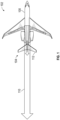
- FIG. 1 an example of an aircraft 100 is illustrated during a braking segment of a landing phase of a flight on a ground surface 102 in accordance with some embodiments.
- Various forces 104 acting on aircraft 100 under differing conditions are shown to help illustrate the benefits and operation of the systems and methods described herein.
- the embodiments described herein are applied to other vehicles.
- freight trucks and trains may have large weight differences between loaded and unloaded conditions.
- Forces 104 include an ideal maximum braking force 110 and a worst-case maximum braking force 112.
- Ideal maximum braking force 110 indicates the amount of braking force the ground surface 102 and braking wheels of aircraft 100 will be able to provide for braking aircraft 100 under dry conditions with the aircraft 100 fully loaded with fuel and passengers.
- Worst-case maximum braking force 112 indicates the amount of braking force the ground surface 102 and braking wheels of aircraft 100 will be able to provide for braking aircraft 100 under wet/slick conditions with aircraft 100 lightly loaded with fuel and passengers.
- ideal maximum braking force 110 is approximately four times larger than worst-case braking force 112.
- Mu tires is the coefficient of friction between the tires and the ground surface.
- N is the normal force acting between aircraft 100 and ground surface 102 perpendicular to ground surface 102.
- the normal force is typically dominated by the weight of the aircraft, but may increase or decrease due to aerodynamic forces when the aircraft is at high speed. Therefore, the maximum braking force decreases with decreasing coefficient of friction (e.g., wet/slick conditions) and decreases with lighter weight aircraft (e.g., lightly loaded with fuel and/or passengers).
- Mu brakes is the coefficient of friction between the brake pads and the rotors of the braking system of aircraft 100. Nbrakes is the force applied by the brake pads on the rotors of the brake system, and is proportional to the brake pressure commanded by the braking system. In the example provided, an anti-skid system effectively limits Fbrake to be less than Fmax, as will be appreciated by those with ordinary skill in the art.
- brake lever 202 is a foot actuated brake pedal.
- multiple pedals provide braking for multiple sets of braking wheels or for different parts of the vehicle.
- a first brake pedal may control braking for the tractor/cab and a second brake pedal may control brakes on the trailer.
- the brake lever is a hand operated handle in the flight deck of the aircraft.
- Brake lever 202 includes a foot support portion 212 and a linking arm portion 214. A pilot of aircraft 100 presses foot support portion 212 to move brake lever through a lever travel 206 between the illustrated resting position and a full lever travel position 204.
- Conventional brake systems utilize a fixed brake pressure relationship where the maximum possible brake pressure is commanded at the full travel position 204.
- the braking wheels lockup depends largely on the ground condition 352 and the vehicle load 312, as illustrated in FIGS. 3A and 3B .
- a traction limit 314 at which the wheels lockup occurs at a higher brake pressure 310 as the vehicle load 312 increases.
- Lever travel 220 illustrates how wheel lockup 221 occurs at the full travel position 204 in heavy loading in dry conditions in both conventional systems and the embodiments described herein.
- Lever travel 222 illustrates how wheel lockup 221 occurs at about half of full pedal position 204 of lever travel 206 in lightly loaded and dry conditions using conventional systems.
- Lever travel 224 illustrates how wheel lockup 221 occurs at about one quarter of full pedal position 204 of lever travel 206 in lightly loaded and wet conditions using conventional systems.
- the embodiments described herein reach wheel lockup 221 at lever travel 230 for all loading and ground surface conditions due to a lever gain that is adjusted according to the method described below.
- lever travel 230 is at the full travel position 204 of brake lever 212.
- full travel refers to the longest travel value that will result in increasing brake pressure applied to the brake system according to the lever gain before adjustment according to task 424 below.
- a brake pressure circuit 250 adjusts the lever gain associated with lever travel 206.
- the term "lever gain” refers to the relationship between lever travel and the hydraulic pressure commanded in brake system 260.
- brake pressure circuit 250 is an electronic circuit that commands brake system 260 based on input from a lever travel sensor 252.
- brake pressure circuit 250 may command a pressure control solenoid to deliver hydraulic fluid to the braking system at a pressure according to the lever travel and the lever gain.
- brake pressure circuit 250 is a mechanically linked system that utilizes mechanical advantage to command higher or lower pressures based on the weight of aircraft 100 and/or other factors.
- Brake system 260 includes an actuator 262 and a braking wheel 264.
- actuator 262 and braking wheel 264 may be conventional braking actuators and braking wheels.
- actuator 262 is a solenoid that selectively permits hydraulic to engage braking rotors.
- actuator 262 is an electronic circuit that manipulates an electronic circuit to provide back EMF to the braking wheel 264. In some embodiments, other types of actuators are utilized.
- FIG. 4 a method 400 of applying brakes to a vehicle is illustrated in accordance with some embodiments.
- Task 410 retrieves a ground condition of a ground on which the vehicle is operating.
- the ground condition indicates the coefficient of friction between the aircraft tires and the runway.
- the ground condition is estimated based on the presence of rain, snow, or other indicators of ground condition.
- Task 412 determines a normal force on the ground at braking tires of the vehicle.
- the weight of the aircraft 100 may double when fully loaded with fuel compared to the same aircraft with a light load of fuel.
- aircraft 100 considers the weight of fuel and cargo as entered by the pilot prior to takeoff.
- a weight sensor on the wheels may be utilized to directly measure the normal force on the ground.
- Task 414 estimates a ground skid pressure of a brake system above which the braking tires slide with respect to the ground. For example, task 414 may utilize eq. 1 to estimate the ground skid pressure based on the normal force and the ground condition.
- Task 416 scales a lever gain of a brake lever to command the ground skid pressure at a full travel position of the brake lever. For example, a computer in aircraft 100 may scale the brake command so full lever travel gives the pilot the full brake capability estimated in task 414.
- Task 418 commands the brake system based on the lever gain.
- hydraulic pressure in the braking system may press a brake shoe into a brake rotor. Friction between brake shoe and rotor creates friction to slow the aircraft.
- the torque in the braking system may come from electrical inductance such as is used in regenerative braking.
- Task 420 determines whether the brake lever is at the full travel position. When the brake lever is at the full travel position, method 400 proceeds to task 422. When the brake lever is not at the full travel position, method 400 returns to task 418.
- Task 422 determines whether an anti-skid system is active. When the anti-skid system is active, method 400 proceeds to task 424. When the anti-skid system is not active, method 400 returns to task 418.
- Task 424 increases the lever gain.
- brake pressure circuit 250 may increase the pressure commanded to brake system 260 for a given lever travel in task 424. Accordingly, if a pilot reaches full lever travel and the anti-skid system has not engaged, then brake pressure will ramp up until reaching the anti-skid limit. In the example provided, brake pressure circuit 250 increases brake pressure when lever travel is beyond 90% of full lever travel if the anti-skid limit is not reached.
Landscapes
- Engineering & Computer Science (AREA)
- Mechanical Engineering (AREA)
- Transportation (AREA)
- Aviation & Aerospace Engineering (AREA)
- Physics & Mathematics (AREA)
- Fluid Mechanics (AREA)
- Regulating Braking Force (AREA)
Description
- The present disclosure generally relates to aircraft braking systems, and more particularly relates to aircraft braking systems that scales a brake pressure gain to command a maximum braking force at a full travel of a brake lever such that a remaining brake lever travel indicates the amount of braking capability remaining for the aircraft.
- Aircraft are equipped with wheel brakes to slow the aircraft while the aircraft is traveling on the ground. The wheel brakes are typically designed to provide more braking power than can be transmitted between the landing gear tires and the runway surface. For example, anti-lock brake functions are typically implemented to reduce the amount of braking applied when the wheels are at risk of becoming locked and sliding across the ground surface.
- The power that can be transmitted between the wheels and the ground surface depends on the environmental conditions, tire properties, ground condition, the normal force on the tires, and other factors. The braking ability of the aircraft may be significantly reduced in wet conditions, in snowy conditions, or when loose gravel or other debris is present on the runway. Reduced braking ability may create difficulties landing the aircraft on short runways or when landing at high speeds.
- Typical aircraft braking systems command brake pressure of the braking system based on brake lever travel distance according to how far the pilot presses the brake lever. In aircraft with anti-skid systems, the anti-skid limit protects from applying more brake pressure than the aircraft can tolerate without causing the tires to skid. When external factors such as runway condition and aircraft weight are considered, this maximum amount of brake pressure can vary significantly. A heavy aircraft on a dry runway will tolerate high brake pressures, which require a large pilot command.
- When the aircraft is lighter (due to lower fuel condition or lighter passenger/cargo loading) and is on a wet or slippery runway, the brake system will only tolerate a low brake pressure before the anti-skid system limits performance. When landing the aircraft at light weights the pilot may command only a modest amount of braking thinking that there is significant additional braking still available because there is a lot of brake lever travel remaining. In fact, the pilot may be using nearly all of the braking capability. The pilot may then infer from the low lever travel that the aircraft braking is more capable than it really is for future stops under similar conditions.
- Accordingly, it is desirable to provide methods, systems, and aircraft that permit increased awareness of the braking capability in various conditions, so the pilot can have a better awareness of remaining braking capability. Furthermore, other desirable features and characteristics of the present disclosure will become apparent from the subsequent detailed description and the appended claims, taken in conjunction with the accompanying drawings and the foregoing technical field and background.
-
US6890041 relates to anti-lock brake systems (ABS) employed on aircraft and land vehicles. - According to the invention, a vehicle includes a brake lever, a braking wheel, and a brake pressure circuit. The brake lever is configured for receiving a driver braking input as a lever travel of the brake lever. The braking wheel is operatively coupled with the brake lever to brake the vehicle based on the lever travel. The brake pressure circuit is configured for: estimating a maximum braking force above which the braking wheel will skid with respect to a ground surface; scaling a lever gain of the brake lever to command the maximum braking force at a full travel of the brake lever such that a remaining brake lever travel indicates the amount of braking capability remaining for the vehicle; and braking the braking wheel based on the lever gain and the lever travel.
- According to a second aspect of the invention, a method of braking a vehicle on a ground surface includes: retrieving a ground condition of a ground surface on which the vehicle is operating; determining a normal force on the ground surface at a braking wheel of the vehicle; estimating a ground skid pressure of a braking system of the vehicle at which the braking wheel begins to slide with respect to the ground surface; scaling a lever gain of a brake lever to command the ground skid pressure at a full travel of the brake lever; and commanding the braking system based on the lever gain.
- Advantages of the present disclosure will be readily appreciated, as the same becomes better understood by reference to the following detailed description when considered in connection with the accompanying drawings wherein:
-
FIG. 1 is a simplified top view of an aircraft during a braking event, in accordance with various embodiments; -
FIG. 2 is a simplified diagram of a brake lever of the aircraft ofFIG. 1 , in accordance with various embodiments; -
FIG. 3A and FIG. 3B are graphs illustrating the relationship between vehicle load and brake pressure and between ground conditions and brake pressure; -
FIG. 4 is a flow chart illustrating a method of braking the aircraft ofFIG. 1 in accordance with various embodiments. - In general, the embodiments described herein improve awareness for the vehicle operator of how much vehicle braking capability remains. Specifically, the remaining brake lever travel indicates to the vehicle operator how much brake capability remains in terms of ground traction. In contrast, the remaining brake lever travel in conventional systems indicates how much hydraulic pressure is available to apply to the braking system regardless of how close the braking is to the traction limit between the wheels and the ground surface. For vehicles with large weight differences between fully loaded and unloaded conditions, (e.g., aircraft, freight trucks), the embodiments provide a significant and noticeable difference to the vehicle operator.
- In addition to awareness of braking capability remaining, the embodiments described herein assist the pilot with comfortable braking for passengers. For example, a lightly loaded aircraft in dry conditions will decelerate very quickly with low commanded brake pressures. By scaling the pressure according to the braking capabilities, the lightly loaded aircraft will decelerate slower for a given lever travel because the lightly loaded aircraft will reach the anti-skid limit at lower brake pressures, as will become apparent from the discussion below.
- Referring now to
FIG. 1 , an example of anaircraft 100 is illustrated during a braking segment of a landing phase of a flight on aground surface 102 in accordance with some embodiments.Various forces 104 acting onaircraft 100 under differing conditions are shown to help illustrate the benefits and operation of the systems and methods described herein. In some embodiments, the embodiments described herein are applied to other vehicles. Notably, freight trucks and trains may have large weight differences between loaded and unloaded conditions. -
Forces 104 include an idealmaximum braking force 110 and a worst-casemaximum braking force 112. Idealmaximum braking force 110 indicates the amount of braking force theground surface 102 and braking wheels ofaircraft 100 will be able to provide for brakingaircraft 100 under dry conditions with theaircraft 100 fully loaded with fuel and passengers. Worst-casemaximum braking force 112 indicates the amount of braking force theground surface 102 and braking wheels ofaircraft 100 will be able to provide for brakingaircraft 100 under wet/slick conditions withaircraft 100 lightly loaded with fuel and passengers. - In the example provided, ideal
maximum braking force 110 is approximately four times larger than worst-case braking force 112. The maximum braking force Fmax is calculated according to eq. 1:

- Mu tires (µtires) is the coefficient of friction between the tires and the ground surface. N is the normal force acting between
aircraft 100 andground surface 102 perpendicular toground surface 102. For a level runway the normal force is typically dominated by the weight of the aircraft, but may increase or decrease due to aerodynamic forces when the aircraft is at high speed. Therefore, the maximum braking force decreases with decreasing coefficient of friction (e.g., wet/slick conditions) and decreases with lighter weight aircraft (e.g., lightly loaded with fuel and/or passengers). - The maximum force applied to the braking wheels from the brake pads (Fbrake) of the aircraft braking system is similarly given according to eq. 2:

- Mu brakes (µbrakes) is the coefficient of friction between the brake pads and the rotors of the braking system of
aircraft 100. Nbrakes is the force applied by the brake pads on the rotors of the brake system, and is proportional to the brake pressure commanded by the braking system. In the example provided, an anti-skid system effectively limits Fbrake to be less than Fmax, as will be appreciated by those with ordinary skill in the art. - In a system with sufficient brake pressure capability to command Fmax to the anti-skid limit at a given weight in dry conditions, deceleration (amax) of aircraft is then given by eq. 3:

- Referring now to
FIGS. 2 ,3A, and 3B , and with continued reference toFIG. 1 , alever travel 200 of abrake lever 202 andtraction limit graphs brake lever 202 is a foot actuated brake pedal. In some embodiments, multiple pedals provide braking for multiple sets of braking wheels or for different parts of the vehicle. For example, in large trucks, a first brake pedal may control braking for the tractor/cab and a second brake pedal may control brakes on the trailer. In some embodiments, the brake lever is a hand operated handle in the flight deck of the aircraft.Brake lever 202 includes afoot support portion 212 and alinking arm portion 214. A pilot ofaircraft 100 pressesfoot support portion 212 to move brake lever through alever travel 206 between the illustrated resting position and a fulllever travel position 204. - Conventional brake systems utilize a fixed brake pressure relationship where the maximum possible brake pressure is commanded at the
full travel position 204. Where the braking wheels lockup depends largely on theground condition 352 and thevehicle load 312, as illustrated inFIGS. 3A and 3B . Atraction limit 314 at which the wheels lockup occurs at ahigher brake pressure 310 as thevehicle load 312 increases. Similarly, atraction limit 354 at which the wheels lockup occurs at ahigher brake pressure 310 with improvingground conditions 352. Accordingly, wheel lockup occurs at the highest pressure in a heavy loaded vehicle with good ground conditions. Conversely, the lowest brake pressure at which wheel lockup occurs is for a lightly loaded vehicle with poor ground surface conditions. -
Lever travel 220 illustrates howwheel lockup 221 occurs at thefull travel position 204 in heavy loading in dry conditions in both conventional systems and the embodiments described herein. Lever travel 222 illustrates howwheel lockup 221 occurs at about half of fullpedal position 204 oflever travel 206 in lightly loaded and dry conditions using conventional systems.Lever travel 224 illustrates howwheel lockup 221 occurs at about one quarter of fullpedal position 204 oflever travel 206 in lightly loaded and wet conditions using conventional systems. In contrast, the embodiments described herein reachwheel lockup 221 atlever travel 230 for all loading and ground surface conditions due to a lever gain that is adjusted according to the method described below. In the example provided,lever travel 230 is at thefull travel position 204 ofbrake lever 212. As used herein, the term "full travel" refers to the longest travel value that will result in increasing brake pressure applied to the brake system according to the lever gain before adjustment according totask 424 below. - A
brake pressure circuit 250 adjusts the lever gain associated withlever travel 206. The term "lever gain" refers to the relationship between lever travel and the hydraulic pressure commanded inbrake system 260. In the example provided,brake pressure circuit 250 is an electronic circuit that commandsbrake system 260 based on input from alever travel sensor 252. For example,brake pressure circuit 250 may command a pressure control solenoid to deliver hydraulic fluid to the braking system at a pressure according to the lever travel and the lever gain. In some embodiments,brake pressure circuit 250 is a mechanically linked system that utilizes mechanical advantage to command higher or lower pressures based on the weight ofaircraft 100 and/or other factors. -
Brake system 260 includes anactuator 262 and abraking wheel 264. For example,actuator 262 andbraking wheel 264 may be conventional braking actuators and braking wheels. In the example provided,actuator 262 is a solenoid that selectively permits hydraulic to engage braking rotors. In some embodiments,actuator 262 is an electronic circuit that manipulates an electronic circuit to provide back EMF to thebraking wheel 264. In some embodiments, other types of actuators are utilized. - Referring now to
FIG. 4 , amethod 400 of applying brakes to a vehicle is illustrated in accordance with some embodiments. -
Task 410 retrieves a ground condition of a ground on which the vehicle is operating. The ground condition indicates the coefficient of friction between the aircraft tires and the runway. In the example provided, the ground condition is estimated based on the presence of rain, snow, or other indicators of ground condition. -
Task 412 determines a normal force on the ground at braking tires of the vehicle. The weight of theaircraft 100 may double when fully loaded with fuel compared to the same aircraft with a light load of fuel. In the example provided,aircraft 100 considers the weight of fuel and cargo as entered by the pilot prior to takeoff. In some embodiments, a weight sensor on the wheels may be utilized to directly measure the normal force on the ground. -
Task 414 estimates a ground skid pressure of a brake system above which the braking tires slide with respect to the ground. For example,task 414 may utilize eq. 1 to estimate the ground skid pressure based on the normal force and the ground condition. - Task 416 scales a lever gain of a brake lever to command the ground skid pressure at a full travel position of the brake lever. For example, a computer in
aircraft 100 may scale the brake command so full lever travel gives the pilot the full brake capability estimated intask 414. -
Task 418 commands the brake system based on the lever gain. For example, hydraulic pressure in the braking system may press a brake shoe into a brake rotor. Friction between brake shoe and rotor creates friction to slow the aircraft. In other embodiments, the torque in the braking system may come from electrical inductance such as is used in regenerative braking. -
Task 420 determines whether the brake lever is at the full travel position. When the brake lever is at the full travel position,method 400 proceeds totask 422. When the brake lever is not at the full travel position,method 400 returns totask 418. -
Task 422 determines whether an anti-skid system is active. When the anti-skid system is active,method 400 proceeds totask 424. When the anti-skid system is not active,method 400 returns totask 418. -
Task 424 increases the lever gain. For example,brake pressure circuit 250 may increase the pressure commanded to brakesystem 260 for a given lever travel intask 424. Accordingly, if a pilot reaches full lever travel and the anti-skid system has not engaged, then brake pressure will ramp up until reaching the anti-skid limit. In the example provided,brake pressure circuit 250 increases brake pressure when lever travel is beyond 90% of full lever travel if the anti-skid limit is not reached.
Claims (10)
- A vehicle, comprising:a brake lever (202) for receiving an operator braking input as a lever travel (206) of the brake lever (202);a braking wheel (264) operatively coupled with the brake lever (202) to brake the vehicle based on the lever travel (206);characterized by:
a brake pressure circuit (250) configured for:estimating a maximum braking force above which the braking wheel (264) will skid with respect to a ground surface;scaling a lever gain of the brake lever (202) to command the maximum braking force at a full travel of the brake lever (204) such that a remaining brake lever travel indicates the amount of braking capability remaining for the vehicle; andbraking the braking wheel (264) based on the lever gain and the lever travel (206). - The vehicle of claim 1, wherein the brake pressure circuit (250) is further configured for retrieving a ground condition (352) of the ground surface, and wherein estimating a maximum braking force is based in part on the ground condition (352).
- The vehicle of claims 1 or 2, wherein the brake pressure circuit (250) is further configured for retrieving a normal force applied on the braking wheel (264) by the ground surface, and wherein estimating the maximum braking force is based in part on the normal force, wherein the brake pressure circuit (250) is optionally further configured for retrieving a weight of the vehicle and for using the weight of the vehicle as an approximation of the normal force.
- The vehicle of any one of claims 1-3, wherein the brake pressure circuit (250) is further configured for increasing the lever gain in response to determining that the brake lever (202) is at or near the full lever travel (204) and an anti-skid brake system has not activated, wherein the brake pressure circuit is optionally configured for increasing the lever gain until the anti-skid system activates while the brake lever (202) is at or near the full lever travel (204) and the anti-skid brake system has not activated.
- The vehicle of any one of claims 1-4, wherein the brake pressure circuit (250) is further configured for using a currently scaled lever gain throughout a braking event in response to detecting that an anti-skid system is active when the brake lever (202) is at less than the full travel (204) to maintain a consistent brake feel throughout the braking event.
- The vehicle of any one of claims 1-5, wherein the brake pressure circuit (250) is further configured for scaling the lever gain using a linear scale.
- The vehicle of any one of claims 1-6, wherein the vehicle is an aircraft (100),
wherein the operator is a pilot, and wherein the vehicle further comprises a brake actuator (262) operatively coupled with the braking wheel (264) to apply a braking force in response to a braking pressure provided to the brake actuator (262). - A method of braking a vehicle on a ground surface, the method comprising:retrieving a ground condition (352) of a ground surface on which the vehicle is operating;determining a normal force on the ground surface at a braking wheel (264) of the vehicle;estimating a ground skid pressure of a braking system of the vehicle at which the braking wheel (264) begins to slide with respect to the ground surface;scaling a lever gain of a brake lever (202) to command the ground skid pressure at a full travel (204) of the brake lever (202); andcommanding the braking system based on the lever gain.
- The method of claim 8, wherein determining the normal force on the ground surface is based on the weight of the vehicle.
- The method of claims 8or 9, further comprising increasing the lever gain in response to determining that the brake lever (202) is at the full lever travel (204) and an anti-skid brake system has not activated, wherein increasing the lever gain optionally includes increasing the lever gain until the anti-skid system activates while the brake lever (202) is at the full lever travel (204) and the anti-skid brake system has not activated.
Applications Claiming Priority (1)
| Application Number | Priority Date | Filing Date | Title |
|---|---|---|---|
| US15/929,781 US11772622B2 (en) | 2020-05-21 | 2020-05-21 | Vehicle brake pedal travel based on braking force available between braking wheels and ground |
Publications (2)
| Publication Number | Publication Date |
|---|---|
| EP3912872A1 EP3912872A1 (en) | 2021-11-24 |
| EP3912872B1 true EP3912872B1 (en) | 2023-08-09 |
Family
ID=75825502
Family Applications (1)
| Application Number | Title | Priority Date | Filing Date |
|---|---|---|---|
| EP21172228.5A Active EP3912872B1 (en) | 2020-05-21 | 2021-05-05 | Vehicle brake pedal travel based on braking force available between braking wheels and ground |
Country Status (3)
| Country | Link |
|---|---|
| US (1) | US11772622B2 (en) |
| EP (1) | EP3912872B1 (en) |
| CN (1) | CN113697092B (en) |
Families Citing this family (2)
| Publication number | Priority date | Publication date | Assignee | Title |
|---|---|---|---|---|
| GB2599167A (en) * | 2020-09-29 | 2022-03-30 | Airbus Operations Ltd | Aircraft system |
| US12162456B2 (en) * | 2021-11-19 | 2024-12-10 | Goodrich Corporation | Feel adjustment braking systems and methods |
Family Cites Families (9)
| Publication number | Priority date | Publication date | Assignee | Title |
|---|---|---|---|---|
| US6890041B1 (en) * | 2001-02-06 | 2005-05-10 | William B. Ribbens | Antilock brake systems employing a sliding mode observer based estimation of differential wheel torque |
| GB0405614D0 (en) | 2004-03-12 | 2004-04-21 | Airbus Uk Ltd | Advanced braking system |
| EP1732796B1 (en) * | 2004-03-12 | 2013-01-23 | Airbus Operations Limited | Advanced braking system for aircraft |
| US7938494B2 (en) | 2006-03-08 | 2011-05-10 | Ribbens William B | Antilock braking systems and methods |
| CN102991488B (en) * | 2012-11-26 | 2014-08-13 | 西安航空制动科技有限公司 | Control method for constant torque of braking system with adaptive capability |
| US9205918B2 (en) * | 2013-11-08 | 2015-12-08 | Goodrich Corporation | System and method for maximum braking |
| CN105934379B (en) * | 2014-01-10 | 2018-09-11 | 海卓-艾尔公司 | It is measured for aircraft brake to mitigate the system and method for structural load |
| GB2540180A (en) | 2015-07-08 | 2017-01-11 | Airbus Operations Ltd | Data processing unit for aircraft undercarriage performance monitoring |
| CN110341944B (en) * | 2019-07-08 | 2024-01-30 | 西安航空制动科技有限公司 | Electric anti-skid brake system with variable gain and variable gain method |
-
2020
- 2020-05-21 US US15/929,781 patent/US11772622B2/en active Active
-
2021
- 2021-05-05 EP EP21172228.5A patent/EP3912872B1/en active Active
- 2021-05-20 CN CN202110553279.6A patent/CN113697092B/en active Active
Also Published As
| Publication number | Publication date |
|---|---|
| CN113697092A (en) | 2021-11-26 |
| US11772622B2 (en) | 2023-10-03 |
| EP3912872A1 (en) | 2021-11-24 |
| CN113697092B (en) | 2025-07-18 |
| US20210362699A1 (en) | 2021-11-25 |
Similar Documents
| Publication | Publication Date | Title |
|---|---|---|
| US5378053A (en) | Maximized regenerative braking vehicle braking controller | |
| US10647320B2 (en) | Method and a system for controlling vehicle speed | |
| EP2081804B1 (en) | Alleviation of aircraft landing gear loading using a brake control scheme | |
| US10576950B2 (en) | Method and a system for controlling vehicle speed | |
| EP1693262A1 (en) | Method and system to reduce carbon brake wear through residual brake force | |
| CN101356085A (en) | Method and system for increasing accuracy of electric brake clamping force | |
| EP3912872B1 (en) | Vehicle brake pedal travel based on braking force available between braking wheels and ground | |
| US11001261B2 (en) | Method and a system for controlling a vehicle during a downhill start | |
| EP4063208B1 (en) | Method of controlling a heavy-duty vehicle in a slope | |
| EP2853487A1 (en) | Brake load alleviation functions | |
| CN114728638B (en) | Method for controlling auxiliary braking of a vehicle | |
| CN110914118A (en) | Utilize the parking brake system to improve vehicle deceleration in the event of a service brake system failure | |
| US12240593B2 (en) | Aircraft brake control system | |
| JPH01164659A (en) | Brake system of traction car | |
| US20090138169A1 (en) | Antilock brake system control device and method | |
| US20250289402A1 (en) | Method for limiting a continuous deceleration effort of a continuous deceleration device | |
| EP3950442B1 (en) | Vehicle braking capability determination by braking with fewer than all available braking wheels | |
| US20060232126A1 (en) | Adaptive braking moment control method | |
| US20220177119A1 (en) | A method of operating an aircraft | |
| EP4431349A1 (en) | Zero-drag control device of emb system and zero-drag control method using the same | |
| JP2001522756A (en) | Braking torque adjustment for vehicles | |
| JPH05294237A (en) | Train brake dispersion control method | |
| WO2019226095A1 (en) | Method and control device for controlling operation of a brake system of a motor vehicle | |
| CN119705384A (en) | A vehicle steep slope descent control method, controller, control system and vehicle | |
| JPH09136634A (en) | Braking force controller |
Legal Events
| Date | Code | Title | Description |
|---|---|---|---|
| PUAI | Public reference made under article 153(3) epc to a published international application that has entered the european phase |
Free format text: ORIGINAL CODE: 0009012 |
|
| STAA | Information on the status of an ep patent application or granted ep patent |
Free format text: STATUS: REQUEST FOR EXAMINATION WAS MADE |
|
| 17P | Request for examination filed |
Effective date: 20210505 |
|
| AK | Designated contracting states |
Kind code of ref document: A1 Designated state(s): AL AT BE BG CH CY CZ DE DK EE ES FI FR GB GR HR HU IE IS IT LI LT LU LV MC MK MT NL NO PL PT RO RS SE SI SK SM TR |
|
| B565 | Issuance of search results under rule 164(2) epc |
Effective date: 20210928 |
|
| STAA | Information on the status of an ep patent application or granted ep patent |
Free format text: STATUS: EXAMINATION IS IN PROGRESS |
|
| 17Q | First examination report despatched |
Effective date: 20220621 |
|
| GRAP | Despatch of communication of intention to grant a patent |
Free format text: ORIGINAL CODE: EPIDOSNIGR1 |
|
| STAA | Information on the status of an ep patent application or granted ep patent |
Free format text: STATUS: GRANT OF PATENT IS INTENDED |
|
| INTG | Intention to grant announced |
Effective date: 20230216 |
|
| GRAS | Grant fee paid |
Free format text: ORIGINAL CODE: EPIDOSNIGR3 |
|
| GRAJ | Information related to disapproval of communication of intention to grant by the applicant or resumption of examination proceedings by the epo deleted |
Free format text: ORIGINAL CODE: EPIDOSDIGR1 |
|
| GRAL | Information related to payment of fee for publishing/printing deleted |
Free format text: ORIGINAL CODE: EPIDOSDIGR3 |
|
| STAA | Information on the status of an ep patent application or granted ep patent |
Free format text: STATUS: EXAMINATION IS IN PROGRESS |
|
| GRAP | Despatch of communication of intention to grant a patent |
Free format text: ORIGINAL CODE: EPIDOSNIGR1 |
|
| STAA | Information on the status of an ep patent application or granted ep patent |
Free format text: STATUS: GRANT OF PATENT IS INTENDED |
|
| P01 | Opt-out of the competence of the unified patent court (upc) registered |
Effective date: 20230519 |
|
| INTC | Intention to grant announced (deleted) | ||
| GRAA | (expected) grant |
Free format text: ORIGINAL CODE: 0009210 |
|
| STAA | Information on the status of an ep patent application or granted ep patent |
Free format text: STATUS: THE PATENT HAS BEEN GRANTED |
|
| INTG | Intention to grant announced |
Effective date: 20230626 |
|
| AK | Designated contracting states |
Kind code of ref document: B1 Designated state(s): AL AT BE BG CH CY CZ DE DK EE ES FI FR GB GR HR HU IE IS IT LI LT LU LV MC MK MT NL NO PL PT RO RS SE SI SK SM TR |
|
| REG | Reference to a national code |
Ref country code: GB Ref legal event code: FG4D |
|
| REG | Reference to a national code |
Ref country code: CH Ref legal event code: EP |
|
| REG | Reference to a national code |
Ref country code: IE Ref legal event code: FG4D |
|
| REG | Reference to a national code |
Ref country code: DE Ref legal event code: R096 Ref document number: 602021004090 Country of ref document: DE |
|
| REG | Reference to a national code |
Ref country code: LT Ref legal event code: MG9D |
|
| REG | Reference to a national code |
Ref country code: NL Ref legal event code: MP Effective date: 20230809 |
|
| REG | Reference to a national code |
Ref country code: AT Ref legal event code: MK05 Ref document number: 1597178 Country of ref document: AT Kind code of ref document: T Effective date: 20230809 |
|
| PG25 | Lapsed in a contracting state [announced via postgrant information from national office to epo] |
Ref country code: GR Free format text: LAPSE BECAUSE OF FAILURE TO SUBMIT A TRANSLATION OF THE DESCRIPTION OR TO PAY THE FEE WITHIN THE PRESCRIBED TIME-LIMIT Effective date: 20231110 |
|
| PG25 | Lapsed in a contracting state [announced via postgrant information from national office to epo] |
Ref country code: IS Free format text: LAPSE BECAUSE OF FAILURE TO SUBMIT A TRANSLATION OF THE DESCRIPTION OR TO PAY THE FEE WITHIN THE PRESCRIBED TIME-LIMIT Effective date: 20231209 |
|
| PG25 | Lapsed in a contracting state [announced via postgrant information from national office to epo] |
Ref country code: SE Free format text: LAPSE BECAUSE OF FAILURE TO SUBMIT A TRANSLATION OF THE DESCRIPTION OR TO PAY THE FEE WITHIN THE PRESCRIBED TIME-LIMIT Effective date: 20230809 Ref country code: RS Free format text: LAPSE BECAUSE OF FAILURE TO SUBMIT A TRANSLATION OF THE DESCRIPTION OR TO PAY THE FEE WITHIN THE PRESCRIBED TIME-LIMIT Effective date: 20230809 Ref country code: PT Free format text: LAPSE BECAUSE OF FAILURE TO SUBMIT A TRANSLATION OF THE DESCRIPTION OR TO PAY THE FEE WITHIN THE PRESCRIBED TIME-LIMIT Effective date: 20231211 Ref country code: NO Free format text: LAPSE BECAUSE OF FAILURE TO SUBMIT A TRANSLATION OF THE DESCRIPTION OR TO PAY THE FEE WITHIN THE PRESCRIBED TIME-LIMIT Effective date: 20231109 Ref country code: NL Free format text: LAPSE BECAUSE OF FAILURE TO SUBMIT A TRANSLATION OF THE DESCRIPTION OR TO PAY THE FEE WITHIN THE PRESCRIBED TIME-LIMIT Effective date: 20230809 Ref country code: LV Free format text: LAPSE BECAUSE OF FAILURE TO SUBMIT A TRANSLATION OF THE DESCRIPTION OR TO PAY THE FEE WITHIN THE PRESCRIBED TIME-LIMIT Effective date: 20230809 Ref country code: LT Free format text: LAPSE BECAUSE OF FAILURE TO SUBMIT A TRANSLATION OF THE DESCRIPTION OR TO PAY THE FEE WITHIN THE PRESCRIBED TIME-LIMIT Effective date: 20230809 Ref country code: IS Free format text: LAPSE BECAUSE OF FAILURE TO SUBMIT A TRANSLATION OF THE DESCRIPTION OR TO PAY THE FEE WITHIN THE PRESCRIBED TIME-LIMIT Effective date: 20231209 Ref country code: HR Free format text: LAPSE BECAUSE OF FAILURE TO SUBMIT A TRANSLATION OF THE DESCRIPTION OR TO PAY THE FEE WITHIN THE PRESCRIBED TIME-LIMIT Effective date: 20230809 Ref country code: GR Free format text: LAPSE BECAUSE OF FAILURE TO SUBMIT A TRANSLATION OF THE DESCRIPTION OR TO PAY THE FEE WITHIN THE PRESCRIBED TIME-LIMIT Effective date: 20231110 Ref country code: FI Free format text: LAPSE BECAUSE OF FAILURE TO SUBMIT A TRANSLATION OF THE DESCRIPTION OR TO PAY THE FEE WITHIN THE PRESCRIBED TIME-LIMIT Effective date: 20230809 Ref country code: AT Free format text: LAPSE BECAUSE OF FAILURE TO SUBMIT A TRANSLATION OF THE DESCRIPTION OR TO PAY THE FEE WITHIN THE PRESCRIBED TIME-LIMIT Effective date: 20230809 |
|
| PG25 | Lapsed in a contracting state [announced via postgrant information from national office to epo] |
Ref country code: PL Free format text: LAPSE BECAUSE OF FAILURE TO SUBMIT A TRANSLATION OF THE DESCRIPTION OR TO PAY THE FEE WITHIN THE PRESCRIBED TIME-LIMIT Effective date: 20230809 |
|
| PG25 | Lapsed in a contracting state [announced via postgrant information from national office to epo] |
Ref country code: ES Free format text: LAPSE BECAUSE OF FAILURE TO SUBMIT A TRANSLATION OF THE DESCRIPTION OR TO PAY THE FEE WITHIN THE PRESCRIBED TIME-LIMIT Effective date: 20230809 |
|
| PG25 | Lapsed in a contracting state [announced via postgrant information from national office to epo] |
Ref country code: SM Free format text: LAPSE BECAUSE OF FAILURE TO SUBMIT A TRANSLATION OF THE DESCRIPTION OR TO PAY THE FEE WITHIN THE PRESCRIBED TIME-LIMIT Effective date: 20230809 Ref country code: RO Free format text: LAPSE BECAUSE OF FAILURE TO SUBMIT A TRANSLATION OF THE DESCRIPTION OR TO PAY THE FEE WITHIN THE PRESCRIBED TIME-LIMIT Effective date: 20230809 Ref country code: ES Free format text: LAPSE BECAUSE OF FAILURE TO SUBMIT A TRANSLATION OF THE DESCRIPTION OR TO PAY THE FEE WITHIN THE PRESCRIBED TIME-LIMIT Effective date: 20230809 Ref country code: EE Free format text: LAPSE BECAUSE OF FAILURE TO SUBMIT A TRANSLATION OF THE DESCRIPTION OR TO PAY THE FEE WITHIN THE PRESCRIBED TIME-LIMIT Effective date: 20230809 Ref country code: DK Free format text: LAPSE BECAUSE OF FAILURE TO SUBMIT A TRANSLATION OF THE DESCRIPTION OR TO PAY THE FEE WITHIN THE PRESCRIBED TIME-LIMIT Effective date: 20230809 Ref country code: CZ Free format text: LAPSE BECAUSE OF FAILURE TO SUBMIT A TRANSLATION OF THE DESCRIPTION OR TO PAY THE FEE WITHIN THE PRESCRIBED TIME-LIMIT Effective date: 20230809 Ref country code: SK Free format text: LAPSE BECAUSE OF FAILURE TO SUBMIT A TRANSLATION OF THE DESCRIPTION OR TO PAY THE FEE WITHIN THE PRESCRIBED TIME-LIMIT Effective date: 20230809 |
|
| REG | Reference to a national code |
Ref country code: DE Ref legal event code: R097 Ref document number: 602021004090 Country of ref document: DE |
|
| PG25 | Lapsed in a contracting state [announced via postgrant information from national office to epo] |
Ref country code: IT Free format text: LAPSE BECAUSE OF FAILURE TO SUBMIT A TRANSLATION OF THE DESCRIPTION OR TO PAY THE FEE WITHIN THE PRESCRIBED TIME-LIMIT Effective date: 20230809 |
|
| PLBE | No opposition filed within time limit |
Free format text: ORIGINAL CODE: 0009261 |
|
| STAA | Information on the status of an ep patent application or granted ep patent |
Free format text: STATUS: NO OPPOSITION FILED WITHIN TIME LIMIT |
|
| 26N | No opposition filed |
Effective date: 20240513 |
|
| PG25 | Lapsed in a contracting state [announced via postgrant information from national office to epo] |
Ref country code: SI Free format text: LAPSE BECAUSE OF FAILURE TO SUBMIT A TRANSLATION OF THE DESCRIPTION OR TO PAY THE FEE WITHIN THE PRESCRIBED TIME-LIMIT Effective date: 20230809 |
|
| PG25 | Lapsed in a contracting state [announced via postgrant information from national office to epo] |
Ref country code: BG Free format text: LAPSE BECAUSE OF FAILURE TO SUBMIT A TRANSLATION OF THE DESCRIPTION OR TO PAY THE FEE WITHIN THE PRESCRIBED TIME-LIMIT Effective date: 20230809 |
|
| PG25 | Lapsed in a contracting state [announced via postgrant information from national office to epo] |
Ref country code: BG Free format text: LAPSE BECAUSE OF FAILURE TO SUBMIT A TRANSLATION OF THE DESCRIPTION OR TO PAY THE FEE WITHIN THE PRESCRIBED TIME-LIMIT Effective date: 20230809 |
|
| REG | Reference to a national code |
Ref country code: CH Ref legal event code: PL |
|
| PG25 | Lapsed in a contracting state [announced via postgrant information from national office to epo] |
Ref country code: MC Free format text: LAPSE BECAUSE OF FAILURE TO SUBMIT A TRANSLATION OF THE DESCRIPTION OR TO PAY THE FEE WITHIN THE PRESCRIBED TIME-LIMIT Effective date: 20230809 |
|
| PG25 | Lapsed in a contracting state [announced via postgrant information from national office to epo] |
Ref country code: LU Free format text: LAPSE BECAUSE OF NON-PAYMENT OF DUE FEES Effective date: 20240505 |
|
| PG25 | Lapsed in a contracting state [announced via postgrant information from national office to epo] |
Ref country code: MC Free format text: LAPSE BECAUSE OF FAILURE TO SUBMIT A TRANSLATION OF THE DESCRIPTION OR TO PAY THE FEE WITHIN THE PRESCRIBED TIME-LIMIT Effective date: 20230809 Ref country code: LU Free format text: LAPSE BECAUSE OF NON-PAYMENT OF DUE FEES Effective date: 20240505 Ref country code: CH Free format text: LAPSE BECAUSE OF NON-PAYMENT OF DUE FEES Effective date: 20240531 |
|
| REG | Reference to a national code |
Ref country code: BE Ref legal event code: MM Effective date: 20240531 |
|
| PG25 | Lapsed in a contracting state [announced via postgrant information from national office to epo] |
Ref country code: IE Free format text: LAPSE BECAUSE OF NON-PAYMENT OF DUE FEES Effective date: 20240505 |
|
| PG25 | Lapsed in a contracting state [announced via postgrant information from national office to epo] |
Ref country code: BE Free format text: LAPSE BECAUSE OF NON-PAYMENT OF DUE FEES Effective date: 20240531 |
|
| PG25 | Lapsed in a contracting state [announced via postgrant information from national office to epo] |
Ref country code: FR Free format text: LAPSE BECAUSE OF NON-PAYMENT OF DUE FEES Effective date: 20240531 |
|
| PGFP | Annual fee paid to national office [announced via postgrant information from national office to epo] |
Ref country code: DE Payment date: 20250403 Year of fee payment: 5 |
|
| PG25 | Lapsed in a contracting state [announced via postgrant information from national office to epo] |
Ref country code: CY Free format text: LAPSE BECAUSE OF FAILURE TO SUBMIT A TRANSLATION OF THE DESCRIPTION OR TO PAY THE FEE WITHIN THE PRESCRIBED TIME-LIMIT; INVALID AB INITIO Effective date: 20210505 |
|
| PG25 | Lapsed in a contracting state [announced via postgrant information from national office to epo] |
Ref country code: HU Free format text: LAPSE BECAUSE OF FAILURE TO SUBMIT A TRANSLATION OF THE DESCRIPTION OR TO PAY THE FEE WITHIN THE PRESCRIBED TIME-LIMIT; INVALID AB INITIO Effective date: 20210505 |
|
| GBPC | Gb: european patent ceased through non-payment of renewal fee |
Effective date: 20250505 |
|
| PG25 | Lapsed in a contracting state [announced via postgrant information from national office to epo] |
Ref country code: GB Free format text: LAPSE BECAUSE OF NON-PAYMENT OF DUE FEES Effective date: 20250505 |