EP3912762A1 - Tool and method for replacing escalator drive spindle - Google Patents
Tool and method for replacing escalator drive spindle Download PDFInfo
- Publication number
- EP3912762A1 EP3912762A1 EP19909780.9A EP19909780A EP3912762A1 EP 3912762 A1 EP3912762 A1 EP 3912762A1 EP 19909780 A EP19909780 A EP 19909780A EP 3912762 A1 EP3912762 A1 EP 3912762A1
- Authority
- EP
- European Patent Office
- Prior art keywords
- tool
- shaft adapter
- original
- central axis
- new
- Prior art date
- Legal status (The legal status is an assumption and is not a legal conclusion. Google has not performed a legal analysis and makes no representation as to the accuracy of the status listed.)
- Granted
Links
Images




Classifications
-
- B—PERFORMING OPERATIONS; TRANSPORTING
- B25—HAND TOOLS; PORTABLE POWER-DRIVEN TOOLS; MANIPULATORS
- B25B—TOOLS OR BENCH DEVICES NOT OTHERWISE PROVIDED FOR, FOR FASTENING, CONNECTING, DISENGAGING, OR HOLDING
- B25B27/00—Hand tools, specially adapted for fitting together or separating parts or objects whether or not involving some deformation, not otherwise provided for
- B25B27/14—Hand tools, specially adapted for fitting together or separating parts or objects whether or not involving some deformation, not otherwise provided for for assembling objects other than by press fit or detaching same
-
- B—PERFORMING OPERATIONS; TRANSPORTING
- B23—MACHINE TOOLS; METAL-WORKING NOT OTHERWISE PROVIDED FOR
- B23P—METAL-WORKING NOT OTHERWISE PROVIDED FOR; COMBINED OPERATIONS; UNIVERSAL MACHINE TOOLS
- B23P6/00—Restoring or reconditioning objects
-
- B—PERFORMING OPERATIONS; TRANSPORTING
- B25—HAND TOOLS; PORTABLE POWER-DRIVEN TOOLS; MANIPULATORS
- B25B—TOOLS OR BENCH DEVICES NOT OTHERWISE PROVIDED FOR, FOR FASTENING, CONNECTING, DISENGAGING, OR HOLDING
- B25B27/00—Hand tools, specially adapted for fitting together or separating parts or objects whether or not involving some deformation, not otherwise provided for
-
- B—PERFORMING OPERATIONS; TRANSPORTING
- B66—HOISTING; LIFTING; HAULING
- B66B—ELEVATORS; ESCALATORS OR MOVING WALKWAYS
- B66B23/00—Component parts of escalators or moving walkways
- B66B23/02—Driving gear
Definitions
- the invention relates to a tool and a method for replacing the drive shaft of escalator or moving walk.
- an auxiliary brake is not mandatorily required for the escalator or moving walk with a rise not higher than 6m.
- a displacement of the driving machine or a failure of the operational brake it may be a need to modernize an escalator or moving walk already in use which has no auxiliary brake.
- the auxiliary brake and the drive shaft are of a coaxial design. Therefore, adding the auxiliary brake function to a drive shaft mounted in the truss is not possible so that the drive shaft of the escalator or the moving walk needs to be removed.
- step chain sprocket In order to ensure a certain ride comfort of the escalator or the moving walk and to prevent the premature failure of the step chain, the step chain sprocket, the drive chain and the drive chain sprocket due to wear or other environmental impacts, it is necessary to strictly determine the relative position between the drive shaft, the truss and the guide rail through special tooling in the assembly workshop to ensure the assembly accuracy.
- Figure 1 shows an escalator or a moving walk in use without auxiliary brake function.
- the relative position between the drive shaft (referred as an original drive shaft 200' herein) and the truss 100 is guaranteed by a special part (referred as an original shaft adapter 300' herein).
- the new shaft adapter 300 see Figure 9
- the new drive shaft equipped with the auxiliary brake function referred as the new drive shaft 200
- the positioning reference of the new drive shaft 200 will be lost due to the replacement of the new shaft adapter 300 and the original shaft adapter 300'. This will cause the position of the new drive shaft 200 with respect to the truss 100 after replacement to be different from that of the original drive shaft 200' with respect to the truss 100 before replacement.
- the present invention has been made to overcome or alleviate at least one aspect of the above-mentioned problems or disadvantages.
- a tool for replacing the drive shaft of escalator or moving walk comprising: a first tool, one side of which is adapted to be assembled on an original shaft adapter, and the other side of which is adapted to be assembled on a new shaft adapter and a second tool adapted to be assembled on the first tool.
- a central axis of the first tool coincides with a central axis of the original shaft adapter.
- a central axis of the second tool coincides with the central axis of the first tool.
- the central axis of the first tool coincides with a central axis of the new shaft adapter.
- the first tool and the original shaft adapter have first positioning features which fit with each other, so that the central axis of the first tool assembled on the original shaft adapter coincides with the central axis of the original shaft adapter.
- a circular concave part is formed on the original shaft adapter and a columnar convex part which is matched with the circular concave part is formed on the first tool.
- the first positioning features include an outer peripheral surface of the cylindrical convex part and an inner peripheral surface of the circular concave part, the outer peripheral surface of the cylindrical convex part is precisely matched with the inner peripheral surface of the circular concave part.
- a first accommodating cavity is formed on one side of the first tool and the original shaft adapter is adapted to be accommodated in the first accommodating cavity.
- the first tool and the second tool have second positioning features which fit with each other, so that the central axis of the second tool assembled on the first tool coincides with the central axis of the original shaft adapter.
- the second tool is circular and adapted to be sleeved on the first tool.
- the second positioning features include an outer peripheral surface of the first tool and an inner peripheral surface of the second tool, and the outer peripheral surface of the first tool is precisely matched with the inner peripheral surface of the second tool.
- a connecting hole corresponding to a threaded hole in the original shaft adapter is formed in the first tool.
- the first tool is adapted to be connected to the original shaft adapter by a first threaded fastener passing through the connecting hole.
- a mounting slot is formed in the second tool, and the second tool is adapted to be connected to a truss of the escalator by a second threaded fastener passing through the mounting slot.
- the first tool and the new shaft adapter have third positioning features which fit with each other, so that the central axis of the first tool assembled on the new shaft adapter coincides with the central axis of the new shaft adapter.
- a second accommodating cavity is formed on the other side of the first tool, and the new shaft adapter is adapted to be accommodated in the second accommodating cavity of the first tool.
- the third positioning features include an inner peripheral surface of the second accommodating cavity and an outer peripheral surface of the new shaft adapter and the inner peripheral surface of the second accommodating cavity of the first tool is precisely matched with the outer peripheral surface of the new shaft adapter.
- a circular concave part is formed on the original shaft adapter and a columnar convex part which is matched with the circular concave part is formed on the first tool.
- the first positioning features include an outer peripheral surface of the cylindrical convex part and an inner peripheral surface of the circular concave part, the outer peripheral surface of the cylindrical convex part is precisely matched with the inner peripheral surface of the circular concave part.
- the first tool is fixed to the original shaft adapter by a first threaded fastener.
- a connecting hole corresponding to a threaded hole in the original shaft adapter is formed in the first tool.
- the first threaded fastener passes through the connecting hole in the first tool and is screwed into the threaded hole in the original shaft adapter, so as to fix the first tool on the original shaft adapter.
- a first accommodating cavity is formed on one side of the first tool, and the original shaft adapter is adapted to be accommodated in the first accommodating cavity.
- the second tool is circular and adapted to be sleeved on the first tool.
- the second positioning features include an outer peripheral surface of the first tool and an inner peripheral surface of the second tool, and the outer peripheral surface of the first tool is precisely matched with the inner peripheral surface of the second tool.
- the second tool is fixed to the truss by a second threaded fastener.
- a mounting slot is formed in the second tool, the second threaded fastener passes through the mounting slot and is threaded to the truss, so as to fix the second tool to the truss.
- a second accommodating cavity is formed on the other side of the first tool, and the new shaft adapter is adapted to be accommodated in the second accommodating cavity of the first tool.
- the third positioning features include an inner peripheral surface of the second accommodating cavity and an outer peripheral surface of the new shaft adapter, and the inner peripheral surface of the second accommodating cavity of the first tool is precisely matched with the outer peripheral surface of the new shaft adapter.
- the new shaft adapter is fixed to the truss by a third threaded fastener.
- a first pin hole is formed in the new shaft adapter and a second pin hole corresponding to the first pin hole is formed in the truss.
- a pin is inserted into the first pin hole and the second pin hole to improve the connection strength between the new shaft adapter and the truss.
- a set of tools for replacing the escalator drive shaft is provided, through which the positioning reference of the original shaft can be accurately transferred to the new drive shaft, so that the new drive shaft can be accurately assembled to the position of the original drive shaft with respect to the truss after replacement. This can ensure that the position of the new drive shaft with respect to the truss after replacement is the same as that of the original drive shaft relative to the truss before replacement.
- a tool for replacing an escalator drive shaft comprising: a first tool, one side of which is adapted to be assembled on an original shaft adapter, and the other side of which is adapted to be assembled on a new shaft adapter; and a second tool adapted to be assembled on the first tool.
- a central axis of the first tool coincides with a central axis of the original shaft adapter; when the second tool is assembled on the first tool, a central axis of the second tool coincides with the central axis of the first tool; when the first tool is assembled on the new shaft adapter, the central axis of the first tool coincides with a central axis of the new shaft adapter.
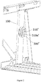
- Figure 1 is an illustrative view of an original drive shaft 200', an original shaft collar 210' and an original shaft adapter 300' installed on a truss 100 before replacement.
- Figure 2 is an illustrative view of removing the original drive shaft 200' and the original shaft collar 210' from the truss 100 and retaining only the original shaft adapter 300'.
- Figure 3 is an illustrative perspective view of a first tool 10 when viewed from one side according to an exemplary embodiment of the present invention.
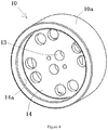
- Figure 4 is an illustrative perspective view of the first tool 10 when viewed from the other side according to an exemplary embodiment of the present invention.
- Figure 6 is an illustrative view of assembling one side of the first tool 10 of Figure 3 on the original shaft adapter 300' of Figure 2 .
- one side of the first tool 10 is adapted to be assembled on the original shaft adapter 300'.
- a central axis of the first tool 10 coincides with a central axis of the original shaft adapter 300'.
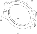
- Figure 5 is an illustrative perspective view of a second tool 20 according to an exemplary embodiment of the present invention.
- Figure 7 is an illustrative view of assembling the second tool 20 of Figure 5 on the first tool 10 of Figure 6 .
- the second tool 20 is adapted to be assembled on the first tool 10.
- a central axis of the second tool 20 coincides with the central axis of the first tool 10.
- Figure 8 is an illustrative view of removing the first tool 10 and the original shaft adapter 300' of Figure 7 from the truss 100.
- Figure 9 is an illustrative view of assembling the first tool 10 and a new shaft adapter 300 on the second tool 20 of Figure 8 .
- the other side of the first tool 10 is adapted to be assembled on the new shaft adapter 300.
- the central axis of the first tool 10 coincides with a central axis of the new shaft adapter 300.
- the first tool 10 and the original shaft adapter 300' have first positioning features 310a', 12a which fit with each other, so that the central axis of the first tool 10 assembled on the original shaft adapter 300' coincides with the central axis of the original shaft adapter 300'.
- a circular concave part 310' is formed on the original shaft adapter 300', and a columnar convex part 12 which is matched with the circular concave part 310'is formed on the first tool 10.
- the first positioning features 310a', 12a include an outer peripheral surface 12a of the cylindrical convex part 12 and an inner peripheral surface 310a' of the circular concave part 310'.
- the outer peripheral surface 12a of the cylindrical convex part 12 is precisely matched with the inner peripheral surface 310a' of the circular concave part 310'.
- a first accommodating cavity 11 is formed on one side of the first tool 10, and the original shaft adapter 300' is adapted to be accommodated in the first accommodating cavity 11.
- the first tool 10 and the second tool 20 have second positioning features 10a, 20a which fit with each other, so that the central axis of the second tool 20 assembled on the first tool 10 coincides with the central axis of the original shaft adapter 300'.
- the second tool 20 is circular and adapted to be sleeved on the first tool 10.
- the second positioning features 10a, 20a include an outer peripheral surface 10a of the first tool 10 and an inner peripheral surface 20a of the second tool 20.
- the outer peripheral surface 10a of the first tool 10 is precisely matched with the inner peripheral surface 20a of the second tool 20.
- a connecting hole 13 corresponding to a threaded hole in the original shaft adapter 300' is formed in the first tool 10.
- the first tool 10 is adapted to be connected to the original shaft adapter 300' by a first threaded fastener 15 passing through the connecting hole 13.
- a mounting slot 21 is formed in the second tool 20, and the second tool 20 is adapted to be connected to the truss 100 of the escalator by a second threaded fastener 25 passing through the mounting slot 21.
- the first tool 10 and the new shaft adapter 300 have third positioning features 300a, 14a which fit with each other, so that the central axis of the first tool 10 assembled on the new shaft adapter 300 coincides with the central axis of the new shaft adapter 300.
- a second accommodating cavity 14 is formed on the other side of the first tool 10, and the new shaft adapter 300 is adapted to be accommodated in the second accommodating cavity 14 of the first tool 10.
- the third positioning features 300a, 14a include an inner peripheral surface 14a of the second accommodating cavity 14 and an outer peripheral surface 300a of the new shaft adapter 300.
- the inner peripheral surface 14a of the second accommodating cavity 14 of the first tool 10 is precisely matched with the outer peripheral surface 300a of the new shaft adapter 300.
- Figure 10 is an illustrative view of removing the first tool 10 and the second tool 20 of Figure 9 from the truss; and Figure 11 is an illustrative view of assembling the new drive shaft 200 and the new shaft collar 210 onto the new shaft adapter 300 of Figure 10 .
- the method for replacing the escalator drive shaft mainly comprises steps of:
- the first tool 10 is fixed to the original shaft adapter 300' by a first threaded fastener 15.
- the second tool 20 is fixed to the truss 100 by a second threaded fastener 25.
- the new shaft adapter 300 is fixed to the truss 100 by a third threaded fastener 301.
- a first pin hole is formed in the new shaft adapter 300, and a second pin hole corresponding to the first pin hole is formed in the truss 100.
- a pin 302 is inserted into the first pin hole and the second pin hole to improve the connection strength between the new shaft adapter 300 and the truss 100.
Landscapes
- Engineering & Computer Science (AREA)
- Mechanical Engineering (AREA)
- Escalators And Moving Walkways (AREA)
- Automatic Assembly (AREA)
- Drilling And Boring (AREA)
Abstract
Description
- The invention relates to a tool and a method for replacing the drive shaft of escalator or moving walk.
- According to EN 115-1; 2017 and
GB 16899-2011 - In a current common design, the auxiliary brake and the drive shaft are of a coaxial design. Therefore, adding the auxiliary brake function to a drive shaft mounted in the truss is not possible so that the drive shaft of the escalator or the moving walk needs to be removed.
- In order to ensure a certain ride comfort of the escalator or the moving walk and to prevent the premature failure of the step chain, the step chain sprocket, the drive chain and the drive chain sprocket due to wear or other environmental impacts, it is necessary to strictly determine the relative position between the drive shaft, the truss and the guide rail through special tooling in the assembly workshop to ensure the assembly accuracy.
-
Figure 1 shows an escalator or a moving walk in use without auxiliary brake function. As shown inFigure 1 , the relative position between the drive shaft (referred as an original drive shaft 200' herein) and thetruss 100 is guaranteed by a special part (referred as an original shaft adapter 300' herein). If the new shaft adapter 300 (seeFigure 9 ) of the new drive shaft equipped with the auxiliary brake function (referred as the new drive shaft 200) is different from the original shaft adapter 300', the positioning reference of thenew drive shaft 200 will be lost due to the replacement of thenew shaft adapter 300 and the original shaft adapter 300'. This will cause the position of thenew drive shaft 200 with respect to thetruss 100 after replacement to be different from that of the original drive shaft 200' with respect to thetruss 100 before replacement. - The present invention has been made to overcome or alleviate at least one aspect of the above-mentioned problems or disadvantages.
- According to an aspect of the present invention, there is provided a tool for replacing the drive shaft of escalator or moving walk, comprising: a first tool, one side of which is adapted to be assembled on an original shaft adapter, and the other side of which is adapted to be assembled on a new shaft adapter and a second tool adapted to be assembled on the first tool. When the first tool is assembled on the original shaft adapter, a central axis of the first tool coincides with a central axis of the original shaft adapter. When the second tool is assembled on the first tool, a central axis of the second tool coincides with the central axis of the first tool. When the first tool is assembled on the new shaft adapter, the central axis of the first tool coincides with a central axis of the new shaft adapter.
- According to an exemplary embodiment of the present invention, the first tool and the original shaft adapter have first positioning features which fit with each other, so that the central axis of the first tool assembled on the original shaft adapter coincides with the central axis of the original shaft adapter.
- According to another exemplary embodiment of the present invention, a circular concave part is formed on the original shaft adapter and a columnar convex part which is matched with the circular concave part is formed on the first tool. The first positioning features include an outer peripheral surface of the cylindrical convex part and an inner peripheral surface of the circular concave part, the outer peripheral surface of the cylindrical convex part is precisely matched with the inner peripheral surface of the circular concave part.
- According to another exemplary embodiment of the present invention, a first accommodating cavity is formed on one side of the first tool and the original shaft adapter is adapted to be accommodated in the first accommodating cavity.
- According to another exemplary embodiment of the present invention, the first tool and the second tool have second positioning features which fit with each other, so that the central axis of the second tool assembled on the first tool coincides with the central axis of the original shaft adapter.
- According to another exemplary embodiment of the present invention, the second tool is circular and adapted to be sleeved on the first tool.
- According to another exemplary embodiment of the present invention, the second positioning features include an outer peripheral surface of the first tool and an inner peripheral surface of the second tool, and the outer peripheral surface of the first tool is precisely matched with the inner peripheral surface of the second tool.
- According to another exemplary embodiment of the present invention, a connecting hole corresponding to a threaded hole in the original shaft adapter is formed in the first tool. The first tool is adapted to be connected to the original shaft adapter by a first threaded fastener passing through the connecting hole.
- According to another exemplary embodiment of the present invention, a mounting slot is formed in the second tool, and the second tool is adapted to be connected to a truss of the escalator by a second threaded fastener passing through the mounting slot.
- According to another exemplary embodiment of the present invention, the first tool and the new shaft adapter have third positioning features which fit with each other, so that the central axis of the first tool assembled on the new shaft adapter coincides with the central axis of the new shaft adapter.
- According to another exemplary embodiment of the present invention, a second accommodating cavity is formed on the other side of the first tool, and the new shaft adapter is adapted to be accommodated in the second accommodating cavity of the first tool.
- According to another exemplary embodiment of the present invention, the third positioning features include an inner peripheral surface of the second accommodating cavity and an outer peripheral surface of the new shaft adapter and the inner peripheral surface of the second accommodating cavity of the first tool is precisely matched with the outer peripheral surface of the new shaft adapter.
- According to another aspect of the present invention, there is provided a method for replacing an escalator drive shaft, comprising steps of:
- S101: removing an original drive shaft and an original shaft collar from a truss of an escalator, and retaining an original shaft adapter matching with the original shaft collar on the truss;
- S102: providing a first tool, and assembling one side of the first tool on the original shaft adapter, wherein the first tool and the original shaft adapter have first positioning features which fit with each other, so that a central axis of the first tool assembled on the original shaft adapter coincides with a central axis of the original shaft adapter;
- S103: providing a second tool, assembling the second tool on the first tool, wherein the first tool and the second tool have second positioning features which fit with each other, so that a central axis of the second tool assembled on the first tool coincides with the central axis of the first tool;
- S104: fixing the second tool on the truss;
- S105: removing the first tool and the original shaft adapter from the truss;
- S106: assembling the other side of the first tool on a new shaft adapter, wherein the first tool and the new shaft adapter have third positioning features which fit with each other, so that the central axis of the first tool assembled on the new shaft adapter coincides with the central axis of the new shaft adapter;
- S107: assembling the first tool and the new shaft adapter into the second tool, wherein the first tool and the second tool matching with each other by the second positioning features, so that the central axis of the new shaft adapter coincides with the central axis of the second tool;
- S108: fixing the new shaft adapter to the truss;
- S109: removing the first tool and the second tool from the truss;
- S110: assembling a new drive shaft and a new shaft collar onto the new shaft adapter.
- According to an exemplary embodiment of the present invention, a circular concave part is formed on the original shaft adapter and a columnar convex part which is matched with the circular concave part is formed on the first tool. The first positioning features include an outer peripheral surface of the cylindrical convex part and an inner peripheral surface of the circular concave part, the outer peripheral surface of the cylindrical convex part is precisely matched with the inner peripheral surface of the circular concave part.
- According to another exemplary embodiment of the present invention, in the step S102, after the first tool is assembled to the original shaft adapter, the first tool is fixed to the original shaft adapter by a first threaded fastener.
- According to another exemplary embodiment of the present invention, a connecting hole corresponding to a threaded hole in the original shaft adapter is formed in the first tool. The first threaded fastener passes through the connecting hole in the first tool and is screwed into the threaded hole in the original shaft adapter, so as to fix the first tool on the original shaft adapter.
- According to another exemplary embodiment of the present invention, a first accommodating cavity is formed on one side of the first tool, and the original shaft adapter is adapted to be accommodated in the first accommodating cavity.
- According to another exemplary embodiment of the present invention, the second tool is circular and adapted to be sleeved on the first tool.
- According to another exemplary embodiment of the present invention, the second positioning features include an outer peripheral surface of the first tool and an inner peripheral surface of the second tool, and the outer peripheral surface of the first tool is precisely matched with the inner peripheral surface of the second tool.
- According to another exemplary embodiment of the present invention, in the step S104, the second tool is fixed to the truss by a second threaded fastener.
- According to another exemplary embodiment of the present invention, a mounting slot is formed in the second tool, the second threaded fastener passes through the mounting slot and is threaded to the truss, so as to fix the second tool to the truss.
- According to another exemplary embodiment of the present invention, a second accommodating cavity is formed on the other side of the first tool, and the new shaft adapter is adapted to be accommodated in the second accommodating cavity of the first tool.
- According to another exemplary embodiment of the present invention, the third positioning features include an inner peripheral surface of the second accommodating cavity and an outer peripheral surface of the new shaft adapter, and the inner peripheral surface of the second accommodating cavity of the first tool is precisely matched with the outer peripheral surface of the new shaft adapter.
- According to another exemplary embodiment of the present invention, in the step S108, the new shaft adapter is fixed to the truss by a third threaded fastener.
- According to another exemplary embodiment of the present invention, a first pin hole is formed in the new shaft adapter and a second pin hole corresponding to the first pin hole is formed in the truss. In the step S109, after the first tool and the second tool are removed from the truss, a pin is inserted into the first pin hole and the second pin hole to improve the connection strength between the new shaft adapter and the truss.
- In the above exemplary embodiments according to the present invention, a set of tools for replacing the escalator drive shaft is provided, through which the positioning reference of the original shaft can be accurately transferred to the new drive shaft, so that the new drive shaft can be accurately assembled to the position of the original drive shaft with respect to the truss after replacement. This can ensure that the position of the new drive shaft with respect to the truss after replacement is the same as that of the original drive shaft relative to the truss before replacement.
- The above and other features of the present invention will become more apparent by describing in detail exemplary embodiments thereof with reference to the accompanying drawings, in which:
-
Figure 1 is an illustrative view of an original drive shaft, an original shaft collar and an original shaft adapter installed on a truss before replacement; -
Figure 2 is an illustrative view of removing the original drive shaft and the original shaft collar from the truss and retaining only the original shaft adapter; -
Figure 3 is an illustrative perspective view of a first tool when viewed from one side according to an exemplary embodiment of the present invention; -
Figure 4 is an illustrative perspective view of the first tool when viewed from the other side according to an exemplary embodiment of the present invention; -
Figure 5 is an illustrative perspective view of a second tool according to an exemplary embodiment of the present invention; -
Figure 6 is an illustrative view of assembling one side of the first tool ofFigure 3 on the original shaft adapter ofFigure 2 ; -
Figure 7 is an illustrative view of assembling the second tool ofFigure 5 on the first tool ofFigure 6 ; -
Figure 8 is an illustrative view of removing the first tool and the original shaft adapter ofFigure 7 from the truss; -
Figure 9 is an illustrative view of assembling the first tool and a new shaft adapter on the second tool ofFigure 8 ; -
Figure 10 is an illustrative view of removing the first tool and the second tool ofFigure 9 from the truss; and -
Figure 11 is an illustrative view of assembling the new drive shaft and the new shaft collar onto the new shaft adapter ofFigure 10 . - Exemplary embodiments of the present disclosure will be described hereinafter in detail with reference to the attached drawings, wherein the like reference numerals refer to the like elements. The present disclosure may, however, be embodied in many different forms and should not be construed as being limited to the embodiment set forth herein; rather, these embodiments are provided so that the present disclosure will be thorough and complete, and will fully convey the concept of the disclosure to those skilled in the art.
- In the following detailed description, for purposes of explanation, numerous specific details are set forth in order to provide a thorough understanding of the disclosed embodiments. It will be apparent, however, that one or more embodiments may be practiced without these specific details. In other instances, well-known structures and devices are schematically shown in order to simplify the drawing.
- According to a general concept of the present invention, there is provided a tool for replacing an escalator drive shaft, comprising: a first tool, one side of which is adapted to be assembled on an original shaft adapter, and the other side of which is adapted to be assembled on a new shaft adapter; and a second tool adapted to be assembled on the first tool. When the first tool is assembled on the original shaft adapter, a central axis of the first tool coincides with a central axis of the original shaft adapter; when the second tool is assembled on the first tool, a central axis of the second tool coincides with the central axis of the first tool; when the first tool is assembled on the new shaft adapter, the central axis of the first tool coincides with a central axis of the new shaft adapter.
- According to another general concept of the present invention, there is provided a method for replacing an escalator drive shaft, comprising steps of:
- removing an original drive shaft and an original shaft collar from a truss of an escalator, and retaining an original shaft adapter matching with the original shaft collar on the truss;
- providing a first tool, and assembling one side of the first tool on the original shaft adapter, wherein the first tool and the original shaft adapter have first positioning features which fit with each other, so that a central axis of the first tool assembled on the original shaft adapter coincides with a central axis of the original shaft adapter;
- providing a second tool, assembling the second tool on the first tool, wherein the first tool and the second tool have second positioning features which fit with each other, so that a central axis of the second tool assembled on the first tool coincides with the central axis of the first tool;
- fixing the second tool on the truss;
- removing the first tool and the original shaft adapter from the truss;
- assembling the other side of the first tool on a new shaft adapter, wherein the first tool and the new shaft adapter have third positioning features which fit with each other, so that the central axis of the first tool assembled on the new shaft adapter coincides with the central axis of the new shaft adapter;
- assembling the first tool and the new shaft adapter into the second tool, wherein the first tool and the second tool matching with each other by the second positioning features, so that the central axis of the new shaft adapter coincides with the central axis of the second tool; fixing the new shaft adapter to the truss; and
- removing the first tool and the second tool from the truss; assembling a new drive shaft and a new shaft collar onto the new shaft adapter.
-
Figure 1 is an illustrative view of an original drive shaft 200', an original shaft collar 210' and an original shaft adapter 300' installed on atruss 100 before replacement.Figure 2 is an illustrative view of removing the original drive shaft 200' and the original shaft collar 210' from thetruss 100 and retaining only the original shaft adapter 300'.Figure 3 is an illustrative perspective view of afirst tool 10 when viewed from one side according to an exemplary embodiment of the present invention.Figure 4 is an illustrative perspective view of thefirst tool 10 when viewed from the other side according to an exemplary embodiment of the present invention.Figure 6 is an illustrative view of assembling one side of thefirst tool 10 ofFigure 3 on the original shaft adapter 300' ofFigure 2 . - As shown in
Figures 1-4 and6 , in an embodiment, one side of thefirst tool 10 is adapted to be assembled on the original shaft adapter 300'. When thefirst tool 10 is assembled on the original shaft adapter 300', a central axis of thefirst tool 10 coincides with a central axis of the original shaft adapter 300'. -
Figure 5 is an illustrative perspective view of asecond tool 20 according to an exemplary embodiment of the present invention.Figure 7 is an illustrative view of assembling thesecond tool 20 ofFigure 5 on thefirst tool 10 ofFigure 6 . - As shown in
Figures 5-7 , in an embodiment, thesecond tool 20 is adapted to be assembled on thefirst tool 10. When thesecond tool 20 is assembled on thefirst tool 10, a central axis of thesecond tool 20 coincides with the central axis of thefirst tool 10. -
Figure 8 is an illustrative view of removing thefirst tool 10 and the original shaft adapter 300' ofFigure 7 from thetruss 100.Figure 9 is an illustrative view of assembling thefirst tool 10 and anew shaft adapter 300 on thesecond tool 20 ofFigure 8 . - As shown in
Figures 1-9 , in an embodiment, the other side of thefirst tool 10 is adapted to be assembled on thenew shaft adapter 300. When thefirst tool 10 is assembled on thenew shaft adapter 300, the central axis of thefirst tool 10 coincides with a central axis of thenew shaft adapter 300. - As shown in
Figures 1-9 , in an embodiment, thefirst tool 10 and the original shaft adapter 300' have first positioning features 310a', 12a which fit with each other, so that the central axis of thefirst tool 10 assembled on the original shaft adapter 300' coincides with the central axis of the original shaft adapter 300'. - As shown in
Figures 1-9 , in an embodiment, a circular concave part 310' is formed on the original shaft adapter 300', and a columnarconvex part 12 which is matched with the circular concave part 310'is formed on thefirst tool 10. The first positioning features 310a', 12a include an outerperipheral surface 12a of the cylindricalconvex part 12 and an innerperipheral surface 310a' of the circular concave part 310'. The outerperipheral surface 12a of the cylindricalconvex part 12 is precisely matched with the innerperipheral surface 310a' of the circular concave part 310'. - As shown in
Figures 1-9 , in an embodiment, a firstaccommodating cavity 11 is formed on one side of thefirst tool 10, and the original shaft adapter 300' is adapted to be accommodated in the first accommodatingcavity 11. - As shown in
Figures 1-9 , in an embodiment, thefirst tool 10 and thesecond tool 20 have second positioning features 10a, 20a which fit with each other, so that the central axis of thesecond tool 20 assembled on thefirst tool 10 coincides with the central axis of the original shaft adapter 300'. - As shown in
Figures 1-9 , in an embodiment, thesecond tool 20 is circular and adapted to be sleeved on thefirst tool 10. - As shown in
Figures 1-9 , in an embodiment, the second positioning features 10a, 20a include an outerperipheral surface 10a of thefirst tool 10 and an innerperipheral surface 20a of thesecond tool 20. The outerperipheral surface 10a of thefirst tool 10 is precisely matched with the innerperipheral surface 20a of thesecond tool 20. - As shown in
Figures 1-9 , in an embodiment, a connectinghole 13 corresponding to a threaded hole in the original shaft adapter 300' is formed in thefirst tool 10. Thefirst tool 10 is adapted to be connected to the original shaft adapter 300' by a first threadedfastener 15 passing through the connectinghole 13. - As shown in
Figures 1-9 , in an embodiment, a mountingslot 21 is formed in thesecond tool 20, and thesecond tool 20 is adapted to be connected to thetruss 100 of the escalator by a second threadedfastener 25 passing through the mountingslot 21. - As shown in
Figures 1-9 , in an embodiment, thefirst tool 10 and thenew shaft adapter 300 have third positioning features 300a, 14a which fit with each other, so that the central axis of thefirst tool 10 assembled on thenew shaft adapter 300 coincides with the central axis of thenew shaft adapter 300. - As shown in
Figures 1-9 , in an embodiment, a secondaccommodating cavity 14 is formed on the other side of thefirst tool 10, and thenew shaft adapter 300 is adapted to be accommodated in the secondaccommodating cavity 14 of thefirst tool 10. - As shown in
Figures 1-9 , in an embodiment, the third positioning features 300a, 14a include an innerperipheral surface 14a of the secondaccommodating cavity 14 and an outerperipheral surface 300a of thenew shaft adapter 300. The innerperipheral surface 14a of the secondaccommodating cavity 14 of thefirst tool 10 is precisely matched with the outerperipheral surface 300a of thenew shaft adapter 300. -
Figure 10 is an illustrative view of removing thefirst tool 10 and thesecond tool 20 ofFigure 9 from the truss; andFigure 11 is an illustrative view of assembling thenew drive shaft 200 and thenew shaft collar 210 onto thenew shaft adapter 300 ofFigure 10 . - Hereafter, it will describe the method for replacing an escalator drive shaft with reference to
Figures 1-11 . The method for replacing the escalator drive shaft mainly comprises steps of: - S101: as shown in
Figures 1-2 , removing an original drive shaft 200' and an original shaft collar 210' from atruss 100 of an escalator, and retaining an original shaft adapter 300' matching with the original shaft collar 210' on thetruss 100; - S102: as shown in
Figures 3-4 and6 , providing afirst tool 10, and assembling one side of thefirst tool 10 on the original shaft adapter 300', wherein thefirst tool 10 and the original shaft adapter 300' have first positioning features 310a', 12a which fit with each other, so that a central axis of thefirst tool 10 assembled on the original shaft adapter 300' coincides with a central axis of the original shaft adapter 300'; - S103: as shown in
Figures 5 and7 , providing asecond tool 20, assembling thesecond tool 20 on thefirst tool 10, wherein thefirst tool 10 and thesecond tool 20 have second positioning features 10a, 20a which fit with each other, so that a central axis of thesecond tool 20 assembled on thefirst tool 10 coincides with the central axis of thefirst tool 10; - S104: as shown in
Figure 7 , fixing thesecond tool 20 on thetruss 100; - S105: as shown in
Figure 8 , removing thefirst tool 10 and the original shaft adapter 300' from thetruss 100; - S106: as shown in
Figure 9 , assembling the other side of thefirst tool 10 on anew shaft adapter 300, wherein thefirst tool 10 and thenew shaft adapter 300 have third positioning features 300a, 14a which fit with each other, so that the central axis of thefirst tool 10 assembled on thenew shaft adapter 300 coincides with the central axis of thenew shaft adapter 300; - S107: as shown in
Figure 9 , assembling thefirst tool 10 and thenew shaft adapter 300 into thesecond tool 20, wherein thefirst tool 10 and thesecond tool 20 matching with each other by the second positioning features 10a, 20a, so that the central axis of thenew shaft adapter 300 coincides with the central axis of thesecond tool 20; - S108: as shown in
Figure 9 , fixing thenew shaft adapter 300 to thetruss 100; - S109: as shown in
Figure 10 , removing thefirst tool 10 and thesecond tool 20 from thetruss 100; - S110: as shown in
Figure 11 , assembling anew drive shaft 200 and anew shaft collar 210 onto thenew shaft adapter 300. - In an embodiment of the present invention, as shown in
Figure 6 , in the step S102, after thefirst tool 10 is assembled to the original shaft adapter 300', thefirst tool 10 is fixed to the original shaft adapter 300' by a first threadedfastener 15. - In an embodiment of the present invention, as shown in
Figure 7 , in the step S104, thesecond tool 20 is fixed to thetruss 100 by a second threadedfastener 25. - In an embodiment of the present invention, as shown in
Figure 9 , in the step S108, thenew shaft adapter 300 is fixed to thetruss 100 by a third threadedfastener 301. - In an embodiment of the present invention, as shown in
Figure 11 , a first pin hole is formed in thenew shaft adapter 300, and a second pin hole corresponding to the first pin hole is formed in thetruss 100. In the step S109, after thefirst tool 10 and thesecond tool 20 are removed from thetruss 100, apin 302 is inserted into the first pin hole and the second pin hole to improve the connection strength between thenew shaft adapter 300 and thetruss 100. - It should be appreciated for those skilled in this art that the above embodiments are intended to be illustrative and not restrictive. For example, many modifications may be made to the above embodiments by those skilled in this art, and various features described in different embodiments may be freely combined with each other without conflicting in configuration or principle.
- Although several exemplary embodiments have been shown and described, it would be appreciated by those skilled in the art that various changes or modifications may be made in these embodiments without departing from the principles and spirit of the disclosure, the scope of which is defined in the claims and their equivalents.
- As used herein, an element recited in the singular and proceeded with the word "a" or "an" should be understood as not excluding plural of said elements or steps, unless such exclusion is explicitly stated. Furthermore, references to "one embodiment" of the present invention are not intended to be interpreted as excluding the existence of additional embodiments that also incorporate the recited features. Moreover, unless explicitly stated to the contrary, embodiments "comprising" or "having" an element or a plurality of elements having a particular property may include additional such elements not having that property.
Claims (25)
- A tool for replacing an escalator drive shaft, comprising:a first tool (10), one side of which is adapted to be assembled on an original shaft adapter (300'), and the other side of which is adapted to be assembled on a new shaft adapter (300); anda second tool (20) adapted to be assembled on the first tool (10),when the first tool (10) is assembled on the original shaft adapter (300'), a central axis of the first tool (10) coincides with a central axis of the original shaft adapter (300'),when the second tool (20) is assembled on the first tool (10), a central axis of the second tool (20) coincides with the central axis of the first tool (10),when the first tool (10) is assembled on the new shaft adapter (300), the central axis of the first tool (10) coincides with a central axis of the new shaft adapter (300).
- The tool for replacing an escalator drive shaft according to claim 1,
wherein the first tool (10) and the original shaft adapter (300') have first positioning features (310a', 12a) which fit with each other, so that the central axis of the first tool (10) assembled on the original shaft adapter (300') coincides with the central axis of the original shaft adapter (300'). - The tool for replacing an escalator drive shaft according to claim 2,wherein a circular concave part (310') is formed on the original shaft adapter (300'), and a columnar convex part (12) which is matched with the circular concave part (310') is formed on the first tool (10);wherein the first positioning features (310a', 12a) include an outer peripheral surface (12a) of the cylindrical convex part (12) and an inner peripheral surface (310a') of the circular concave part (310'),the outer peripheral surface (12a) of the cylindrical convex part (12) is precisely matched with the inner peripheral surface (310a') of the circular concave part (310').
- The tool for replacing an escalator drive shaft according to claim 1,
wherein a first accommodating cavity (11) is formed on one side of the first tool (10), and the original shaft adapter (300') is adapted to be accommodated in the first accommodating cavity (11). - The tool for replacing an escalator drive shaft according to claim 1,
wherein the first tool (10) and the second tool (20) have second positioning features (10a, 20a) which fit with each other, so that the central axis of the second tool (20) assembled on the first tool (10) coincides with the central axis of the original shaft adapter (300'). - The tool for replacing an escalator drive shaft according to claim 5,
wherein the second tool (20) is circular and adapted to be sleeved on the first tool (10). - The tool for replacing an escalator drive shaft according to claim 6,
wherein the second positioning features (10a, 20a) include an outer peripheral surface (10a) of the first tool (10) and an inner peripheral surface (20a) of the second tool (20), and the outer peripheral surface (10a) of the first tool (10) is precisely matched with the inner peripheral surface (20a) of the second tool (20). - The tool for replacing an escalator drive shaft according to claim 1,wherein a connecting hole (13) corresponding to a threaded hole in the original shaft adapter (300') is formed in the first tool (10);wherein the first tool (10) is adapted to be connected to the original shaft adapter (300') by a first threaded fastener (15) passing through the connecting hole (13).
- The tool for replacing an escalator drive shaft according to claim 1,
wherein a mounting slot (21) is formed in the second tool (20), and the second tool (20) is adapted to be connected to a truss (100) of the escalator by a second threaded fastener (25) passing through the mounting slot (21). - The tool for replacing an escalator drive shaft according to claim 1,
wherein the first tool (10) and the new shaft adapter (300) have third positioning features (300a,14a) which fit with each other, so that the central axis of the first tool (10) assembled on the new shaft adapter (300) coincides with the central axis of the new shaft adapter (300). - The tool for replacing an escalator drive shaft according to claim 10,
wherein a second accommodating cavity (14) is formed on the other side of the first tool (10), and the new shaft adapter (300) is adapted to be accommodated in the second accommodating cavity (14) of the first tool (10). - The tool for replacing an escalator drive shaft according to claim 11,
wherein the third positioning features (300a, 14a) include an inner peripheral surface (14a) of the second accommodating cavity (14) and an outer peripheral surface (300a) of the new shaft adapter (300), and the inner peripheral surface (14a) of the second accommodating cavity (14) of the first tool (10) is precisely matched with the outer peripheral surface (300a) of the new shaft adapter (300). - A method for replacing an escalator drive shaft, comprising the steps of:S101: removing an original drive shaft (200') and an original shaft collar (210') from a truss (100) of an escalator, and retaining an original shaft adapter (300') matching with the original shaft collar (210') on the truss (100);S102: providing a first tool (10), and assembling one side of the first tool (10) on the original shaft adapter (300'), wherein the first tool (10) and the original shaft adapter (300') have first positioning features (310a', 12a) which fit with each other, so that a central axis of the first tool (10) assembled on the original shaft adapter (300') coincides with a central axis of the original shaft adapter (300');S103: providing a second tool (20), assembling the second tool (20) on the first tool (10), wherein the first tool (10) and the second tool (20) have second positioning features (10a, 20a) which fit with each other, so that a central axis of the second tool (20) assembled on the first tool (10) coincides with the central axis of the first tool (10);S104: fixing the second tool (20) on the truss (100);S105: removing the first tool (10) and the original shaft adapter (300') from the truss (100);S106: assembling the other side of the first tool (10) on a new shaft adapter (300), wherein the first tool (10) and the new shaft adapter (300) have third positioning features (300a, 14a) which fit with each other, so that the central axis of the first tool (10) assembled on the new shaft adapter (300) coincides with the central axis of the new shaft adapter (300);S107: assembling the first tool (10) and the new shaft adapter (300) into the second tool (20), wherein the first tool (10) and the second tool (20) matching with each other by the second positioning features (10a, 20a), so that the central axis of the new shaft adapter (300) coincides with the central axis of the second tool (20);S108: fixing the new shaft adapter (300) to the truss (100);S109: removing the first tool (10) and the second tool (20) from the truss (100);S110: assembling a new drive shaft (200) and a new shaft collar (210) onto the new shaft adapter (300).
- The method according to claim 13,wherein a circular concave part (310') is formed on the original shaft adapter (300'), and a columnar convex part (12) which is matched with the circular concave part (310')is formed on the first tool (10);wherein the first positioning features (310a', 12a) include an outer peripheral surface (12a) of the cylindrical convex part (12) and an inner peripheral surface (310a') of the circular concave part (310'),the outer peripheral surface (12a) of the cylindrical convex part (12) is precisely matched with the inner peripheral surface (310a') of the circular concave part (310').
- The method according to claim 13, wherein
in the step S102, after the first tool (10) is assembled to the original shaft adapter (300'), the first tool (10) is fixed to the original shaft adapter (300') by a first threaded fastener (15). - The method according to claim 15,wherein a connecting hole (13) corresponding to a threaded hole in the original shaft adapter (300') is formed in the first tool (10);wherein the first threaded fastener (15) passes through the connecting hole (13) in the first tool (10) and is screwed into the threaded hole in the original shaft adapter (300'), so as to fix the first tool (10) on the original shaft adapter (300').
- The method according to claim 13,
wherein a first accommodating cavity (11) is formed on one side of the first tool (10), and the original shaft adapter (300') is adapted to be accommodated in the first accommodating cavity (11). - The method according to claim 13,
wherein the second tool (20) is circular and adapted to be sleeved on the first tool (10). - The method according to claim 18,
wherein the second positioning features (10a, 20a) include an outer peripheral surface (10a) of the first tool (10) and an inner peripheral surface (20a) of the second tool (20), and the outer peripheral surface (10a) of the first tool (10) is precisely matched with the inner peripheral surface (20a) of the second tool (20). - The method according to claim 13, wherein
in the step S104, the second tool (20) is fixed to the truss (100) by a second threaded fastener (25). - The method according to claim 20,
wherein a mounting slot (21) is formed in the second tool (20), the second threaded fastener (25) passes through the mounting slot (21) and is threaded to the truss (100), so as to fix the second tool (20) to the truss (100). - The method according to claim 13,
wherein a second accommodating cavity (14) is formed on the other side of the first tool (10), and the new shaft adapter (300) is adapted to be accommodated in the second accommodating cavity (14) of the first tool (10). - The method according to claim 22,
wherein the third positioning features (300a, 14a) include an inner peripheral surface (14a) of the second accommodating cavity (14) and an outer peripheral surface (300a) of the new shaft adapter (300), and the inner peripheral surface (14a) of the second accommodating cavity (14) of the first tool (10) is precisely matched with the outer peripheral surface (300a) of the new shaft adapter (300). - The method according to claim 13, wherein
in the step S108, the new shaft adapter (300) is fixed to the truss (100) by a third threaded fastener (301). - The method according to claim 13,wherein a first pin hole is formed in the new shaft adapter (300), and a second pin hole corresponding to the first pin hole is formed in the truss (100);in the step S109, after the first tool (10) and the second tool (20) are removed from the truss (100), a pin (302) is inserted into the first pin hole and the second pin hole to improve the connection strength between the new shaft adapter (300) and the truss (100).
Applications Claiming Priority (3)
| Application Number | Priority Date | Filing Date | Title |
|---|---|---|---|
| CN201910030589.2A CN109732525B (en) | 2019-01-14 | 2019-01-14 | Tool for replacing escalator drive spindle |
| CN201910030571.2A CN109732507B (en) | 2019-01-14 | 2019-01-14 | Method for replacing escalator drive spindle |
| PCT/CN2019/116258 WO2020147382A1 (en) | 2019-01-14 | 2019-11-07 | Tool and method for replacing escalator drive spindle |
Publications (3)
| Publication Number | Publication Date |
|---|---|
| EP3912762A1 true EP3912762A1 (en) | 2021-11-24 |
| EP3912762A4 EP3912762A4 (en) | 2022-09-07 |
| EP3912762B1 EP3912762B1 (en) | 2024-06-26 |
Family
ID=71613519
Family Applications (1)
| Application Number | Title | Priority Date | Filing Date |
|---|---|---|---|
| EP19909780.9A Active EP3912762B1 (en) | 2019-01-14 | 2019-11-07 | Tool and method for replacing escalator drive spindle |
Country Status (3)
| Country | Link |
|---|---|
| US (1) | US11590615B2 (en) |
| EP (1) | EP3912762B1 (en) |
| WO (1) | WO2020147382A1 (en) |
Family Cites Families (11)
| Publication number | Priority date | Publication date | Assignee | Title |
|---|---|---|---|---|
| JP2744156B2 (en) * | 1991-10-14 | 1998-04-28 | 株式会社日立ビルシステム | Bearing nut removal device |
| JP3482329B2 (en) * | 1997-11-12 | 2003-12-22 | 株式会社日立ビルシステム | Terminal gear bearing driving device for ultra-high head escalator |
| MY121131A (en) * | 1999-01-13 | 2005-12-30 | Inventio Ag | Device and method for simplifying the replacement of bearings on an escalator of moving walkway |
| US8112855B1 (en) * | 2009-04-24 | 2012-02-14 | Balliew James W | Tool for the removal and reassembly of cylinder valve caps |
| CN202106337U (en) * | 2011-06-15 | 2012-01-11 | 山东潍坊福田模具有限责任公司 | Dismantling device of inner ring of main shaft of pentahedral machine tool |
| CN202292633U (en) * | 2011-10-25 | 2012-07-04 | 陈希林 | New removing tool |
| CN203426952U (en) * | 2013-08-05 | 2014-02-12 | 咸德企业有限公司 | Disassembling tool for close-fitting cantilever assembly |
| US9956674B2 (en) | 2016-01-26 | 2018-05-01 | Ford Global Technologies, Llc | Replacement tool for driveshaft yoke bushings |
| CN209427943U (en) * | 2018-12-07 | 2019-09-24 | 迅达(中国)电梯有限公司 | Staircase driving spindle mounting device |
| CN109732507B (en) * | 2019-01-14 | 2020-06-05 | 迅达(中国)电梯有限公司 | Method for replacing escalator drive spindle |
| CN109732525B (en) * | 2019-01-14 | 2020-07-31 | 迅达(中国)电梯有限公司 | Tool for replacing escalator drive spindle |
-
2019
- 2019-11-07 WO PCT/CN2019/116258 patent/WO2020147382A1/en not_active Ceased
- 2019-11-07 US US17/310,048 patent/US11590615B2/en active Active
- 2019-11-07 EP EP19909780.9A patent/EP3912762B1/en active Active
Also Published As
| Publication number | Publication date |
|---|---|
| WO2020147382A1 (en) | 2020-07-23 |
| EP3912762A4 (en) | 2022-09-07 |
| EP3912762B1 (en) | 2024-06-26 |
| US11590615B2 (en) | 2023-02-28 |
| US20220048144A1 (en) | 2022-02-17 |
Similar Documents
| Publication | Publication Date | Title |
|---|---|---|
| EP3415781B1 (en) | Guide assembly | |
| CN106369087B (en) | Disc brake component | |
| EP3912762B1 (en) | Tool and method for replacing escalator drive spindle | |
| JP2011212769A (en) | Tool holding and conveying chain | |
| AU2020345426A1 (en) | Tooth attachment structure for bucket and tooth for bucket | |
| ITMI930727A1 (en) | ASSEMBLY ARRANGEMENT OF A TOOL HOLDER IN A MACHINE TOOL | |
| US6047795A (en) | Mounting member for disk brake and method of producing the same | |
| CN109732507B (en) | Method for replacing escalator drive spindle | |
| CN109732525B (en) | Tool for replacing escalator drive spindle | |
| US20120184383A1 (en) | Transmission shaft for transmitting rotational movements and/or forces, and method for manufacturing said shaft | |
| US7305759B2 (en) | Device for the manufacture of a shaft assembly for a hydrodynamic bearing | |
| CN103449291B (en) | The guide boot method for dismounting of apparatus of passenger conveyor and guide boot withdrawing device | |
| CA2867825C (en) | Coupler assembly | |
| EP1201339A2 (en) | An apparatus for positioning a cutter of a tool relative to the spindle of a machine tool | |
| JP5352082B2 (en) | Passenger conveyor and passenger conveyor tread roller | |
| US20040250528A1 (en) | Width adjustable chain tool | |
| CN215525086U (en) | Detection apparatus for steering device | |
| US20140334753A1 (en) | Cylinder assembly using a shim | |
| EP2104409A2 (en) | Precision alignment assembly for rack mount guidance and navigation system | |
| JP4955376B2 (en) | Punching mold | |
| CN222873877U (en) | A crankshaft spline machining error prevention mechanism and crankshaft machining system | |
| JP2011121149A (en) | Shaft pin mounting tool | |
| KR101438820B1 (en) | Vehicle punch retainer assembly | |
| CN217594940U (en) | Universal vehicle door limiting tool for automobile | |
| CN212823943U (en) | Concave-convex arc machining tool for thin wall |
Legal Events
| Date | Code | Title | Description |
|---|---|---|---|
| STAA | Information on the status of an ep patent application or granted ep patent |
Free format text: STATUS: THE INTERNATIONAL PUBLICATION HAS BEEN MADE |
|
| PUAI | Public reference made under article 153(3) epc to a published international application that has entered the european phase |
Free format text: ORIGINAL CODE: 0009012 |
|
| STAA | Information on the status of an ep patent application or granted ep patent |
Free format text: STATUS: REQUEST FOR EXAMINATION WAS MADE |
|
| 17P | Request for examination filed |
Effective date: 20210407 |
|
| AK | Designated contracting states |
Kind code of ref document: A1 Designated state(s): AL AT BE BG CH CY CZ DE DK EE ES FI FR GB GR HR HU IE IS IT LI LT LU LV MC MK MT NL NO PL PT RO RS SE SI SK SM TR |
|
| DAV | Request for validation of the european patent (deleted) | ||
| DAX | Request for extension of the european patent (deleted) | ||
| A4 | Supplementary search report drawn up and despatched |
Effective date: 20220809 |
|
| RIC1 | Information provided on ipc code assigned before grant |
Ipc: B25B 27/14 20060101ALN20220803BHEP Ipc: B25B 11/00 20060101ALI20220803BHEP Ipc: B25B 27/00 20060101AFI20220803BHEP |
|
| RAP3 | Party data changed (applicant data changed or rights of an application transferred) |
Owner name: INVENTIO AG |
|
| STAA | Information on the status of an ep patent application or granted ep patent |
Free format text: STATUS: EXAMINATION IS IN PROGRESS |
|
| 17Q | First examination report despatched |
Effective date: 20230713 |
|
| GRAP | Despatch of communication of intention to grant a patent |
Free format text: ORIGINAL CODE: EPIDOSNIGR1 |
|
| STAA | Information on the status of an ep patent application or granted ep patent |
Free format text: STATUS: GRANT OF PATENT IS INTENDED |
|
| RIC1 | Information provided on ipc code assigned before grant |
Ipc: B25B 27/14 20060101ALN20240311BHEP Ipc: B25B 11/00 20060101ALI20240311BHEP Ipc: B25B 27/00 20060101AFI20240311BHEP |
|
| INTG | Intention to grant announced |
Effective date: 20240326 |
|
| GRAS | Grant fee paid |
Free format text: ORIGINAL CODE: EPIDOSNIGR3 |
|
| GRAA | (expected) grant |
Free format text: ORIGINAL CODE: 0009210 |
|
| STAA | Information on the status of an ep patent application or granted ep patent |
Free format text: STATUS: THE PATENT HAS BEEN GRANTED |
|
| AK | Designated contracting states |
Kind code of ref document: B1 Designated state(s): AL AT BE BG CH CY CZ DE DK EE ES FI FR GB GR HR HU IE IS IT LI LT LU LV MC MK MT NL NO PL PT RO RS SE SI SK SM TR |
|
| REG | Reference to a national code |
Ref country code: GB Ref legal event code: FG4D |
|
| REG | Reference to a national code |
Ref country code: CH Ref legal event code: EP |
|
| REG | Reference to a national code |
Ref country code: DE Ref legal event code: R096 Ref document number: 602019054405 Country of ref document: DE |
|
| PG25 | Lapsed in a contracting state [announced via postgrant information from national office to epo] |
Ref country code: BG Free format text: LAPSE BECAUSE OF FAILURE TO SUBMIT A TRANSLATION OF THE DESCRIPTION OR TO PAY THE FEE WITHIN THE PRESCRIBED TIME-LIMIT Effective date: 20240626 |
|
| PG25 | Lapsed in a contracting state [announced via postgrant information from national office to epo] |
Ref country code: FI Free format text: LAPSE BECAUSE OF FAILURE TO SUBMIT A TRANSLATION OF THE DESCRIPTION OR TO PAY THE FEE WITHIN THE PRESCRIBED TIME-LIMIT Effective date: 20240626 Ref country code: HR Free format text: LAPSE BECAUSE OF FAILURE TO SUBMIT A TRANSLATION OF THE DESCRIPTION OR TO PAY THE FEE WITHIN THE PRESCRIBED TIME-LIMIT Effective date: 20240626 |
|
| REG | Reference to a national code |
Ref country code: LT Ref legal event code: MG9D |
|
| PG25 | Lapsed in a contracting state [announced via postgrant information from national office to epo] |
Ref country code: GR Free format text: LAPSE BECAUSE OF FAILURE TO SUBMIT A TRANSLATION OF THE DESCRIPTION OR TO PAY THE FEE WITHIN THE PRESCRIBED TIME-LIMIT Effective date: 20240927 |
|
| PG25 | Lapsed in a contracting state [announced via postgrant information from national office to epo] |
Ref country code: LV Free format text: LAPSE BECAUSE OF FAILURE TO SUBMIT A TRANSLATION OF THE DESCRIPTION OR TO PAY THE FEE WITHIN THE PRESCRIBED TIME-LIMIT Effective date: 20240626 |
|
| REG | Reference to a national code |
Ref country code: NL Ref legal event code: MP Effective date: 20240626 |
|
| PG25 | Lapsed in a contracting state [announced via postgrant information from national office to epo] |
Ref country code: NO Free format text: LAPSE BECAUSE OF FAILURE TO SUBMIT A TRANSLATION OF THE DESCRIPTION OR TO PAY THE FEE WITHIN THE PRESCRIBED TIME-LIMIT Effective date: 20240926 Ref country code: LV Free format text: LAPSE BECAUSE OF FAILURE TO SUBMIT A TRANSLATION OF THE DESCRIPTION OR TO PAY THE FEE WITHIN THE PRESCRIBED TIME-LIMIT Effective date: 20240626 Ref country code: HR Free format text: LAPSE BECAUSE OF FAILURE TO SUBMIT A TRANSLATION OF THE DESCRIPTION OR TO PAY THE FEE WITHIN THE PRESCRIBED TIME-LIMIT Effective date: 20240626 Ref country code: GR Free format text: LAPSE BECAUSE OF FAILURE TO SUBMIT A TRANSLATION OF THE DESCRIPTION OR TO PAY THE FEE WITHIN THE PRESCRIBED TIME-LIMIT Effective date: 20240927 Ref country code: FI Free format text: LAPSE BECAUSE OF FAILURE TO SUBMIT A TRANSLATION OF THE DESCRIPTION OR TO PAY THE FEE WITHIN THE PRESCRIBED TIME-LIMIT Effective date: 20240626 Ref country code: BG Free format text: LAPSE BECAUSE OF FAILURE TO SUBMIT A TRANSLATION OF THE DESCRIPTION OR TO PAY THE FEE WITHIN THE PRESCRIBED TIME-LIMIT Effective date: 20240626 Ref country code: RS Free format text: LAPSE BECAUSE OF FAILURE TO SUBMIT A TRANSLATION OF THE DESCRIPTION OR TO PAY THE FEE WITHIN THE PRESCRIBED TIME-LIMIT Effective date: 20240926 |
|
| PG25 | Lapsed in a contracting state [announced via postgrant information from national office to epo] |
Ref country code: NL Free format text: LAPSE BECAUSE OF FAILURE TO SUBMIT A TRANSLATION OF THE DESCRIPTION OR TO PAY THE FEE WITHIN THE PRESCRIBED TIME-LIMIT Effective date: 20240626 |
|
| REG | Reference to a national code |
Ref country code: AT Ref legal event code: MK05 Ref document number: 1697325 Country of ref document: AT Kind code of ref document: T Effective date: 20240626 |
|
| PG25 | Lapsed in a contracting state [announced via postgrant information from national office to epo] |
Ref country code: NL Free format text: LAPSE BECAUSE OF FAILURE TO SUBMIT A TRANSLATION OF THE DESCRIPTION OR TO PAY THE FEE WITHIN THE PRESCRIBED TIME-LIMIT Effective date: 20240626 |
|
| PG25 | Lapsed in a contracting state [announced via postgrant information from national office to epo] |
Ref country code: PT Free format text: LAPSE BECAUSE OF FAILURE TO SUBMIT A TRANSLATION OF THE DESCRIPTION OR TO PAY THE FEE WITHIN THE PRESCRIBED TIME-LIMIT Effective date: 20241028 |
|
| PG25 | Lapsed in a contracting state [announced via postgrant information from national office to epo] |
Ref country code: PT Free format text: LAPSE BECAUSE OF FAILURE TO SUBMIT A TRANSLATION OF THE DESCRIPTION OR TO PAY THE FEE WITHIN THE PRESCRIBED TIME-LIMIT Effective date: 20241028 |
|
| PG25 | Lapsed in a contracting state [announced via postgrant information from national office to epo] |
Ref country code: PL Free format text: LAPSE BECAUSE OF FAILURE TO SUBMIT A TRANSLATION OF THE DESCRIPTION OR TO PAY THE FEE WITHIN THE PRESCRIBED TIME-LIMIT Effective date: 20240626 |
|
| PGFP | Annual fee paid to national office [announced via postgrant information from national office to epo] |
Ref country code: FR Payment date: 20241126 Year of fee payment: 6 |
|
| PG25 | Lapsed in a contracting state [announced via postgrant information from national office to epo] |
Ref country code: EE Free format text: LAPSE BECAUSE OF FAILURE TO SUBMIT A TRANSLATION OF THE DESCRIPTION OR TO PAY THE FEE WITHIN THE PRESCRIBED TIME-LIMIT Effective date: 20240626 |
|
| PG25 | Lapsed in a contracting state [announced via postgrant information from national office to epo] |
Ref country code: AT Free format text: LAPSE BECAUSE OF FAILURE TO SUBMIT A TRANSLATION OF THE DESCRIPTION OR TO PAY THE FEE WITHIN THE PRESCRIBED TIME-LIMIT Effective date: 20240626 Ref country code: IS Free format text: LAPSE BECAUSE OF FAILURE TO SUBMIT A TRANSLATION OF THE DESCRIPTION OR TO PAY THE FEE WITHIN THE PRESCRIBED TIME-LIMIT Effective date: 20241026 |
|
| PG25 | Lapsed in a contracting state [announced via postgrant information from national office to epo] |
Ref country code: CZ Free format text: LAPSE BECAUSE OF FAILURE TO SUBMIT A TRANSLATION OF THE DESCRIPTION OR TO PAY THE FEE WITHIN THE PRESCRIBED TIME-LIMIT Effective date: 20240626 |
|
| PG25 | Lapsed in a contracting state [announced via postgrant information from national office to epo] |
Ref country code: RO Free format text: LAPSE BECAUSE OF FAILURE TO SUBMIT A TRANSLATION OF THE DESCRIPTION OR TO PAY THE FEE WITHIN THE PRESCRIBED TIME-LIMIT Effective date: 20240626 Ref country code: SK Free format text: LAPSE BECAUSE OF FAILURE TO SUBMIT A TRANSLATION OF THE DESCRIPTION OR TO PAY THE FEE WITHIN THE PRESCRIBED TIME-LIMIT Effective date: 20240626 |
|
| PG25 | Lapsed in a contracting state [announced via postgrant information from national office to epo] |
Ref country code: SM Free format text: LAPSE BECAUSE OF FAILURE TO SUBMIT A TRANSLATION OF THE DESCRIPTION OR TO PAY THE FEE WITHIN THE PRESCRIBED TIME-LIMIT Effective date: 20240626 Ref country code: ES Free format text: LAPSE BECAUSE OF FAILURE TO SUBMIT A TRANSLATION OF THE DESCRIPTION OR TO PAY THE FEE WITHIN THE PRESCRIBED TIME-LIMIT Effective date: 20240626 |
|
| PGFP | Annual fee paid to national office [announced via postgrant information from national office to epo] |
Ref country code: IT Payment date: 20241125 Year of fee payment: 6 |
|
| PG25 | Lapsed in a contracting state [announced via postgrant information from national office to epo] |
Ref country code: SM Free format text: LAPSE BECAUSE OF FAILURE TO SUBMIT A TRANSLATION OF THE DESCRIPTION OR TO PAY THE FEE WITHIN THE PRESCRIBED TIME-LIMIT Effective date: 20240626 Ref country code: SK Free format text: LAPSE BECAUSE OF FAILURE TO SUBMIT A TRANSLATION OF THE DESCRIPTION OR TO PAY THE FEE WITHIN THE PRESCRIBED TIME-LIMIT Effective date: 20240626 Ref country code: RO Free format text: LAPSE BECAUSE OF FAILURE TO SUBMIT A TRANSLATION OF THE DESCRIPTION OR TO PAY THE FEE WITHIN THE PRESCRIBED TIME-LIMIT Effective date: 20240626 Ref country code: PL Free format text: LAPSE BECAUSE OF FAILURE TO SUBMIT A TRANSLATION OF THE DESCRIPTION OR TO PAY THE FEE WITHIN THE PRESCRIBED TIME-LIMIT Effective date: 20240626 Ref country code: IS Free format text: LAPSE BECAUSE OF FAILURE TO SUBMIT A TRANSLATION OF THE DESCRIPTION OR TO PAY THE FEE WITHIN THE PRESCRIBED TIME-LIMIT Effective date: 20241026 Ref country code: ES Free format text: LAPSE BECAUSE OF FAILURE TO SUBMIT A TRANSLATION OF THE DESCRIPTION OR TO PAY THE FEE WITHIN THE PRESCRIBED TIME-LIMIT Effective date: 20240626 Ref country code: EE Free format text: LAPSE BECAUSE OF FAILURE TO SUBMIT A TRANSLATION OF THE DESCRIPTION OR TO PAY THE FEE WITHIN THE PRESCRIBED TIME-LIMIT Effective date: 20240626 Ref country code: CZ Free format text: LAPSE BECAUSE OF FAILURE TO SUBMIT A TRANSLATION OF THE DESCRIPTION OR TO PAY THE FEE WITHIN THE PRESCRIBED TIME-LIMIT Effective date: 20240626 Ref country code: AT Free format text: LAPSE BECAUSE OF FAILURE TO SUBMIT A TRANSLATION OF THE DESCRIPTION OR TO PAY THE FEE WITHIN THE PRESCRIBED TIME-LIMIT Effective date: 20240626 |
|
| PGFP | Annual fee paid to national office [announced via postgrant information from national office to epo] |
Ref country code: CH Payment date: 20241201 Year of fee payment: 6 |
|
| REG | Reference to a national code |
Ref country code: DE Ref legal event code: R097 Ref document number: 602019054405 Country of ref document: DE |
|
| PG25 | Lapsed in a contracting state [announced via postgrant information from national office to epo] |
Ref country code: DK Free format text: LAPSE BECAUSE OF FAILURE TO SUBMIT A TRANSLATION OF THE DESCRIPTION OR TO PAY THE FEE WITHIN THE PRESCRIBED TIME-LIMIT Effective date: 20240626 |
|
| PLBE | No opposition filed within time limit |
Free format text: ORIGINAL CODE: 0009261 |
|
| STAA | Information on the status of an ep patent application or granted ep patent |
Free format text: STATUS: NO OPPOSITION FILED WITHIN TIME LIMIT |
|
| 26N | No opposition filed |
Effective date: 20250327 |
|
| PG25 | Lapsed in a contracting state [announced via postgrant information from national office to epo] |
Ref country code: MC Free format text: LAPSE BECAUSE OF FAILURE TO SUBMIT A TRANSLATION OF THE DESCRIPTION OR TO PAY THE FEE WITHIN THE PRESCRIBED TIME-LIMIT Effective date: 20240626 |
|
| PG25 | Lapsed in a contracting state [announced via postgrant information from national office to epo] |
Ref country code: LU Free format text: LAPSE BECAUSE OF NON-PAYMENT OF DUE FEES Effective date: 20241107 |
|
| GBPC | Gb: european patent ceased through non-payment of renewal fee |
Effective date: 20241107 |
|
| REG | Reference to a national code |
Ref country code: BE Ref legal event code: MM Effective date: 20241130 |
|
| PG25 | Lapsed in a contracting state [announced via postgrant information from national office to epo] |
Ref country code: SE Free format text: LAPSE BECAUSE OF FAILURE TO SUBMIT A TRANSLATION OF THE DESCRIPTION OR TO PAY THE FEE WITHIN THE PRESCRIBED TIME-LIMIT Effective date: 20240626 |
|
| PG25 | Lapsed in a contracting state [announced via postgrant information from national office to epo] |
Ref country code: BE Free format text: LAPSE BECAUSE OF NON-PAYMENT OF DUE FEES Effective date: 20241130 Ref country code: GB Free format text: LAPSE BECAUSE OF NON-PAYMENT OF DUE FEES Effective date: 20241107 |
|
| PG25 | Lapsed in a contracting state [announced via postgrant information from national office to epo] |
Ref country code: IE Free format text: LAPSE BECAUSE OF NON-PAYMENT OF DUE FEES Effective date: 20241107 |
|
| PGFP | Annual fee paid to national office [announced via postgrant information from national office to epo] |
Ref country code: DE Payment date: 20251126 Year of fee payment: 7 |
|
| PG25 | Lapsed in a contracting state [announced via postgrant information from national office to epo] |
Ref country code: HU Free format text: LAPSE BECAUSE OF FAILURE TO SUBMIT A TRANSLATION OF THE DESCRIPTION OR TO PAY THE FEE WITHIN THE PRESCRIBED TIME-LIMIT; INVALID AB INITIO Effective date: 20191107 |
|
| PG25 | Lapsed in a contracting state [announced via postgrant information from national office to epo] |
Ref country code: CY Free format text: LAPSE BECAUSE OF FAILURE TO SUBMIT A TRANSLATION OF THE DESCRIPTION OR TO PAY THE FEE WITHIN THE PRESCRIBED TIME-LIMIT; INVALID AB INITIO Effective date: 20191107 |