EP3912559A1 - Puncture needle, ultrasonic diagnostic device, and method for controlling ultrasonic diagnostic device - Google Patents
Puncture needle, ultrasonic diagnostic device, and method for controlling ultrasonic diagnostic device Download PDFInfo
- Publication number
- EP3912559A1 EP3912559A1 EP19909721.3A EP19909721A EP3912559A1 EP 3912559 A1 EP3912559 A1 EP 3912559A1 EP 19909721 A EP19909721 A EP 19909721A EP 3912559 A1 EP3912559 A1 EP 3912559A1
- Authority
- EP
- European Patent Office
- Prior art keywords
- processed
- needle tip
- tip part
- arithmetic progression
- ultrasound
- Prior art date
- Legal status (The legal status is an assumption and is not a legal conclusion. Google has not performed a legal analysis and makes no representation as to the accuracy of the status listed.)
- Granted
Links
Images




Classifications
-
- A—HUMAN NECESSITIES
- A61—MEDICAL OR VETERINARY SCIENCE; HYGIENE
- A61B—DIAGNOSIS; SURGERY; IDENTIFICATION
- A61B8/00—Diagnosis using ultrasonic, sonic or infrasonic waves
- A61B8/54—Control of the diagnostic device
-
- A—HUMAN NECESSITIES
- A61—MEDICAL OR VETERINARY SCIENCE; HYGIENE
- A61B—DIAGNOSIS; SURGERY; IDENTIFICATION
- A61B10/00—Instruments for taking body samples for diagnostic purposes; Other methods or instruments for diagnosis, e.g. for vaccination diagnosis, sex determination or ovulation-period determination; Throat striking implements
- A61B10/02—Instruments for taking cell samples or for biopsy
-
- A—HUMAN NECESSITIES
- A61—MEDICAL OR VETERINARY SCIENCE; HYGIENE
- A61B—DIAGNOSIS; SURGERY; IDENTIFICATION
- A61B8/00—Diagnosis using ultrasonic, sonic or infrasonic waves
- A61B8/08—Clinical applications
- A61B8/0833—Clinical applications involving detecting or locating foreign bodies or organic structures
- A61B8/0841—Clinical applications involving detecting or locating foreign bodies or organic structures for locating instruments
-
- A—HUMAN NECESSITIES
- A61—MEDICAL OR VETERINARY SCIENCE; HYGIENE
- A61B—DIAGNOSIS; SURGERY; IDENTIFICATION
- A61B8/00—Diagnosis using ultrasonic, sonic or infrasonic waves
- A61B8/44—Constructional features of the ultrasonic, sonic or infrasonic diagnostic device
- A61B8/4483—Constructional features of the ultrasonic, sonic or infrasonic diagnostic device characterised by features of the ultrasound transducer
- A61B8/4488—Constructional features of the ultrasonic, sonic or infrasonic diagnostic device characterised by features of the ultrasound transducer the transducer being a phased array
-
- A—HUMAN NECESSITIES
- A61—MEDICAL OR VETERINARY SCIENCE; HYGIENE
- A61B—DIAGNOSIS; SURGERY; IDENTIFICATION
- A61B8/00—Diagnosis using ultrasonic, sonic or infrasonic waves
- A61B8/46—Ultrasonic, sonic or infrasonic diagnostic devices with special arrangements for interfacing with the operator or the patient
- A61B8/461—Displaying means of special interest
-
- A—HUMAN NECESSITIES
- A61—MEDICAL OR VETERINARY SCIENCE; HYGIENE
- A61B—DIAGNOSIS; SURGERY; IDENTIFICATION
- A61B8/00—Diagnosis using ultrasonic, sonic or infrasonic waves
- A61B8/52—Devices using data or image processing specially adapted for diagnosis using ultrasonic, sonic or infrasonic waves
- A61B8/5207—Devices using data or image processing specially adapted for diagnosis using ultrasonic, sonic or infrasonic waves involving processing of raw data to produce diagnostic data, e.g. for generating an image
-
- A—HUMAN NECESSITIES
- A61—MEDICAL OR VETERINARY SCIENCE; HYGIENE
- A61B—DIAGNOSIS; SURGERY; IDENTIFICATION
- A61B8/00—Diagnosis using ultrasonic, sonic or infrasonic waves
- A61B8/52—Devices using data or image processing specially adapted for diagnosis using ultrasonic, sonic or infrasonic waves
- A61B8/5215—Devices using data or image processing specially adapted for diagnosis using ultrasonic, sonic or infrasonic waves involving processing of medical diagnostic data
-
- A—HUMAN NECESSITIES
- A61—MEDICAL OR VETERINARY SCIENCE; HYGIENE
- A61B—DIAGNOSIS; SURGERY; IDENTIFICATION
- A61B8/00—Diagnosis using ultrasonic, sonic or infrasonic waves
- A61B8/52—Devices using data or image processing specially adapted for diagnosis using ultrasonic, sonic or infrasonic waves
- A61B8/5215—Devices using data or image processing specially adapted for diagnosis using ultrasonic, sonic or infrasonic waves involving processing of medical diagnostic data
- A61B8/5223—Devices using data or image processing specially adapted for diagnosis using ultrasonic, sonic or infrasonic waves involving processing of medical diagnostic data for extracting a diagnostic or physiological parameter from medical diagnostic data
-
- A—HUMAN NECESSITIES
- A61—MEDICAL OR VETERINARY SCIENCE; HYGIENE
- A61B—DIAGNOSIS; SURGERY; IDENTIFICATION
- A61B8/00—Diagnosis using ultrasonic, sonic or infrasonic waves
- A61B8/52—Devices using data or image processing specially adapted for diagnosis using ultrasonic, sonic or infrasonic waves
- A61B8/5269—Devices using data or image processing specially adapted for diagnosis using ultrasonic, sonic or infrasonic waves involving detection or reduction of artifacts
-
- A—HUMAN NECESSITIES
- A61—MEDICAL OR VETERINARY SCIENCE; HYGIENE
- A61B—DIAGNOSIS; SURGERY; IDENTIFICATION
- A61B17/00—Surgical instruments, devices or methods
- A61B17/34—Trocars; Puncturing needles
- A61B17/3403—Needle locating or guiding means
- A61B2017/3413—Needle locating or guiding means guided by ultrasound
-
- A—HUMAN NECESSITIES
- A61—MEDICAL OR VETERINARY SCIENCE; HYGIENE
- A61B—DIAGNOSIS; SURGERY; IDENTIFICATION
- A61B34/00—Computer-aided surgery; Manipulators or robots specially adapted for use in surgery
- A61B34/20—Surgical navigation systems; Devices for tracking or guiding surgical instruments, e.g. for frameless stereotaxis
- A61B2034/2046—Tracking techniques
- A61B2034/2065—Tracking using image or pattern recognition
-
- A—HUMAN NECESSITIES
- A61—MEDICAL OR VETERINARY SCIENCE; HYGIENE
- A61B—DIAGNOSIS; SURGERY; IDENTIFICATION
- A61B90/00—Instruments, implements or accessories specially adapted for surgery or diagnosis and not covered by any of the groups A61B1/00 - A61B50/00, e.g. for luxation treatment or for protecting wound edges
- A61B90/36—Image-producing devices or illumination devices not otherwise provided for
- A61B90/37—Surgical systems with images on a monitor during operation
- A61B2090/378—Surgical systems with images on a monitor during operation using ultrasound
-
- A—HUMAN NECESSITIES
- A61—MEDICAL OR VETERINARY SCIENCE; HYGIENE
- A61B—DIAGNOSIS; SURGERY; IDENTIFICATION
- A61B8/00—Diagnosis using ultrasonic, sonic or infrasonic waves
- A61B8/56—Details of data transmission or power supply
- A61B8/565—Details of data transmission or power supply involving data transmission via a network
Definitions
- the present invention relates to a puncture needle, an ultrasound diagnostic apparatus that detects a puncture needle inserted into a subject, and a control method of the ultrasound diagnostic apparatus.
- the ultrasound diagnostic apparatus comprises an ultrasound probe provided with a transducer array in which a plurality of elements are arranged.
- an ultrasound beam is transmitted from the transducer array toward an inside of the subject, and an ultrasound echo from the subject is received by the transducer array to obtain element data.
- the ultrasound diagnostic apparatus electrically processes the obtained element data to generate an ultrasound image for a relevant part of the subject.
- the puncture needle since the puncture needle is usually inserted in an inclined state with respect to the body surface of the subject, the ultrasound echo reflected from the puncture needle in the subject is difficult to propagate toward the ultrasound probe, and the puncture needle is sometimes not clearly depicted in the ultrasound image. Therefore, in order to clearly depict the puncture needle in the ultrasound image, for example, as disclosed in JP2011-125632A , a puncture needle which is processed to reflect an ultrasound beam from an ultrasound probe has been developed. A plurality of grooves for reflecting an ultrasound beam are formed on an outer peripheral part of the puncture needle of JP2011-125632A .
- the puncture needle of JP2011-125632A is inserted into a subject and the inserted puncture needle is irradiated with an ultrasound beam
- the ultrasound beam applied to the puncture needle is reflected by the plurality of grooves formed in the puncture needle and propagates toward the ultrasound probe.
- the plurality of grooves formed in the puncture needle are depicted in the ultrasound image.
- a position of a puncture needle may be confirmed by providing a light absorbing portion on a part of a surface of the puncture needle.
- the groove of the puncture needle on the ultrasound image is sometimes concealed or disappears due to a high-intensity reflection signal, an acoustic shadow, or the like derived from a tissue in a subject.
- a position of the groove in the puncture needle is not specified, and it is sometimes difficult for the user to estimate a position of the tip part of the puncture needle.
- the light absorbing portion is provided on the part of the surface of the puncture needle as in JP5635462B , a cost of the puncture needle is increased.
- the present invention has been made to solve such a conventional problem, and an object of the present invention is to provide a puncture needle, an ultrasound diagnostic apparatus, and a control method of the ultrasound diagnostic apparatus, with which a user can accurately grasp a tip part of the puncture needle.
- a puncture needle comprises a shaft part, a needle tip part disposed at a tip of the shaft part, and a plurality of processed parts that are arranged on an outer peripheral part of the shaft part along a length direction of the shaft part and form an arithmetic progression in which arrangement intervals gradually decrease toward the needle tip part, in which among the plurality of processed parts, an arrangement interval between a first processed part which is separated from the needle tip part by a predetermined distance and is closest to the needle tip part and a second processed part which is second closest to the needle tip part is equal to or less than a tolerance of the arithmetic progression, or a distance from the needle tip part to the first processed part which is closest to the needle tip part is equal to or less than the tolerance of the arithmetic progression and equal to a difference between the arrangement interval between the first processed part and the second processed part which is second closest to the needle tip part and the tolerance.
- the plurality of processed parts are grooves formed to surround a periphery of the shaft part.
- An ultrasound diagnostic apparatus comprises a display unit that displays an ultrasound image in which the puncture needle is captured, an arrangement interval detection unit that recognizes the plurality of processed parts of the puncture needle and detects the arrangement intervals of the plurality of processed parts by image analysis of the ultrasound image, an arithmetic progression determination unit that determines whether or not the arrangement intervals of the plurality of processed parts detected by the arrangement interval detection unit form the arithmetic progression, a first processed part detection unit that calculates the tolerance of the arithmetic progression and detects the first processed part which is closest to the needle tip part among the plurality of processed parts based on the tolerance in a case where the arithmetic progression determination unit determines that the arithmetic progression is formed, and a needle tip part position estimation unit that estimates a position of the needle tip part based on a position of the first processed part detected by the first processed part detection unit.
- the needle tip part position estimation unit may estimate a point extending from the first processed part to a tip side of the shaft part by the predetermined distance as the position of the needle tip part in a case where the arrangement interval between the first processed part and the second processed part of the puncture needle is equal to or less than the tolerance of the arithmetic progression, and estimate a point extending from the first processed part to the tip side of the shaft part by the difference between the arrangement interval between the first processed part and the second processed part and the tolerance as the position of the needle tip part in a case where the distance from the needle tip part to the first processed part of the puncture needle is equal to or less than the tolerance of the arithmetic progression and equal to the difference between the arrangement interval between the first processed part and the second processed part and the tolerance.
- the needle tip part position estimation unit displays the estimated position of the needle tip part on the display unit.
- the ultrasound diagnostic apparatus may further comprise an ultrasound probe and an image acquisition unit that acquires the ultrasound image by performing transmission and reception of an ultrasound beam between the ultrasound probe and a subject.
- the display unit may display the ultrasound image acquired by the image acquisition unit
- the arrangement interval detection unit may recognize the plurality of processed parts of the puncture needle and detect the arrangement intervals of the plurality of processed parts by image analysis of the ultrasound image acquired by the image acquisition unit.
- a control method of an ultrasound diagnostic apparatus comprises displaying an ultrasound image in which the puncture needle is captured, recognizing the plurality of processed parts of the puncture needle and detecting the arrangement intervals of the plurality of processed parts by image analysis of the ultrasound image, determining whether or not the detected arrangement intervals of the plurality of processed parts form the arithmetic progression, calculating the tolerance of the arithmetic progression and detecting the first processed part which is closest to the needle tip part among the plurality of processed parts based on the tolerance in a case where determination is made that the arithmetic progression is formed, and estimating a position of the needle tip part based on a position of the detected first processed part.
- a puncture needle comprises a shaft part, a needle tip part disposed at a tip of the shaft part, and a plurality of processed parts that are arranged on an outer peripheral part of the shaft part along a length direction of the shaft part and form an arithmetic progression in which arrangement intervals gradually decrease toward the needle tip part, in which among the plurality of processed parts, an arrangement interval between a first processed part which is separated from the needle tip part by a predetermined distance and is closest to the needle tip part and a second processed part which is second closest to the needle tip part is equal to or less than a tolerance of the arithmetic progression, or a distance from the needle tip part to the first processed part which is closest to the needle tip part is equal to or less than the tolerance of the arithmetic progression and equal to a difference between the arrangement interval between the first processed part and the second processed part which is second closest to the needle tip part and the tolerance. Therefore, a user can accurately grasp the tip part of the puncture needle.
- Fig. 1 shows a puncture needle N1 according to Embodiment 1 of the present invention.
- the puncture needle N1 is inserted into a subject in order to place a catheter, a drug, or the like in the subject, and comprises a shaft part S and a sharp needle tip part T formed by obliquely cutting out a tip part of the shaft part S and disposed at a tip of the shaft part S.
- a plurality of processed parts P1 to P7 formed of grooves formed to surround a periphery of the shaft part S are arranged and formed along a length direction of the shaft part S.
- an arrangement interval L1 between the first processed part P1 and the second processed part P2, an arrangement interval L2 between the second processed part P2 and the third processed part P3, an arrangement interval L3 between the third processed part P3 and the fourth processed part P4, an arrangement interval L4 between the fourth processed part P4 and the fifth processed part P5, an arrangement interval L5 between the fifth processed part P5 and the sixth processed part P6, and an arrangement interval L6 between the sixth processed part P6 and the seventh processed part P7 form an arithmetic progression in which values gradually decrease toward the needle tip part T.
- the term "the arrangement intervals form the arithmetic progression" means that values of the arrangement intervals form the arithmetic progression, and that in a case where values of the arrangement intervals L1 to L6 are integers and are aligned to a specific unit such as mm, the values form the arithmetic progression. Therefore, in the arrangement intervals L1 to L6 of the plurality of processed parts P1 to P7, a difference between arrangement intervals adjacent to each other is a so-called tolerance of the arithmetic progression and each has the same value.
- the arrangement interval L1 between the first processed part P1 which is separated from the needle tip part T by a predetermined distance K and is closest to the needle tip part T and the second processed part P2 which is second closest to the needle tip part T is designed to be equal to or less than the tolerance of the arithmetic progression formed by the arrangement intervals of the plurality of processed parts P1 to P7.
- the first processed part P1 to the seventh processed part P7 can form an arithmetic progression with a tolerance of 5 mm
- the first processed part P1 to the seventh processed part P7 can be formed such that the arrangement interval L1 between the first processed part P1 and the second processed part P2 is equal to the tolerance of 5 mm.
- a formation position of the first processed part P1 can be appropriately set according to the specifications of the puncture needle N1, such as an outer diameter of the shaft part S and the inclination angle of the inclined surface E with respect to the extending direction of the shaft part S.
- the puncture needle N1 according to Embodiment 1 of the present invention as described above is irradiated with an ultrasound beam from an ultrasound probe 2 in contact with a body surface B of the subject while being inserted into the subject.
- the ultrasound beam applied to the puncture needle is reflected by the plurality of processed parts P1 to P7, and the reflected ultrasound beam propagates toward the ultrasound probe 2.
- the puncture needle N1 is imaged by the ultrasound probe 2
- a plurality of processed parts P1 to P7 of the puncture needle N1 are depicted in an ultrasound image.
- the first processed part P1 is formed on the base end side of the shaft part S from the inclined surface E, the first processed part P1 can be depicted in the ultrasound image regardless of a rotation angle around a central axis of the puncture needle N1.
- the ultrasound diagnostic apparatus 1 images the puncture needle N1 inserted into the subject.
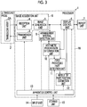
- the ultrasound diagnostic apparatus 1 comprises the ultrasound probe 2 incorporating a transducer array 2A, and a transmission unit 3 and a reception unit 4 are connected to the transducer array 2A.
- An image generation unit 5, a display control unit 6, and a display unit 7 are sequentially connected to the reception unit 4.
- an image acquisition unit 8 is constituted of the transmission unit 3, the reception unit 4, and the image generation unit 5.
- an arrangement interval detection unit 9 is connected to the image generation unit 5, and an arithmetic progression determination unit 10 and a first processed part detection unit 11 are connected to the arrangement interval detection unit 9.
- the display control unit 6 and the first processed part detection unit 11 are connected to the arithmetic progression determination unit 10.
- a needle tip part position estimation unit 12 is connected to the first processed part detection unit 11, and the display control unit 6 is connected to the needle tip part position estimation unit 12.
- an apparatus control unit 13 is connected to the display control unit 6, the image acquisition unit 8, the arrangement interval detection unit 9, the arithmetic progression determination unit 10, the first processed part detection unit 11, and the needle tip part position estimation unit 12, and an input unit 14 and a storage unit 15 are connected to the apparatus control unit 13.
- the apparatus control unit 13 and the storage unit 15 are connected to each other so that information can be exchanged in both directions.
- a processor 16 is constituted of the display control unit 6, the image acquisition unit 8, the arrangement interval detection unit 9, the arithmetic progression determination unit 10, the first processed part detection unit 11, the needle tip part position estimation unit 12, and the apparatus control unit 13.
- the transducer array 2A of the ultrasound probe 2 shown in Fig. 3 has a plurality of transducers arranged one-dimensionally or two-dimensionally. Each of these transducers transmits an ultrasonic wave in accordance with a drive signal supplied from the transmission unit 3, and receives an ultrasound echo from the subject to output a reception signal.
- Each transducer is constituted by forming electrodes on both ends of a piezoelectric body made of, for example, a piezoelectric ceramic represented by lead zirconate titanate (PZT), a polymer piezoelectric element represented by poly vinylidene di fluoride (PMN-PT: polyvinylidene fluoride), and a piezoelectric single crystal represented by lead magnesium niobate-lead titanate (PMN-PT: lead magnesium niobate-lead titanate solid solution).
- PZT lead zirconate titanate
- PMN-PT polymer piezoelectric element represented by poly vinylidene di fluoride
- PMN-PT piezoelectric single crystal represented by lead magnesium niobate-lead titanate
- the transmission unit 3 of the image acquisition unit 8 includes, for example, a plurality of pulse generators, and based on a transmission delay pattern selected in accordance with a control signal from the apparatus control unit 13, supplies the drive signals to the plurality of transducers by adjusting the delay amount so that the ultrasonic waves transmitted from the plurality of transducers of the transducer array 2A form an ultrasound beam.
- a pulsed or continuous wave voltage is applied to the electrodes of the plurality of transducers of the transducer array 2A, the piezoelectric body expands and contracts, pulsed or continuous wave ultrasonic waves are generated from the transducers, and an ultrasound beam is formed from a composite wave of the ultrasonic waves.
- the transmitted ultrasound beam is reflected at an object such as a part of the subject and propagates toward the transducer array 2A of the ultrasound probe 2.
- the ultrasound echo propagating toward the transducer array 2A in this way is received by each of the transducers constituting the transducer array 2A.
- each transducer constituting the transducer array 2A expands and contracts by receiving the propagating ultrasound echo to generate an electric signal, and outputs these electric signals to the reception unit 4.
- the reception unit 4 of the image acquisition unit 8 processes a signal output from the transducer array 2A in accordance with the control signal from the apparatus control unit 13.
- the reception unit 4 has a configuration in which an amplification unit 17 and an analog digital (AD) conversion unit 18 are connected in series.
- the amplification unit 17 amplifies the signal received from each of the transducers constituting the transducer array 2A, and transmits the amplified signal to the AD conversion unit 18.
- the AD conversion unit 18 converts the signal transmitted from the amplification unit 17 into a digitized reception signal, and sends these pieces of data to the image generation unit 5 of the image acquisition unit 8.
- the image generation unit 5 of the image acquisition unit 8 has a configuration in which a signal processing unit 19, a digital scan converter (DSC) 20, and an image processing unit 21 are sequentially connected in series.
- the signal processing unit 19 performs reception focus processing by applying a delay to each piece of data of the reception signal based on a reception delay pattern selected in accordance with the control signal from the apparatus control unit 13, and adding up the results (phase-adjusted addition).
- reception focus processing a sound ray signal in which a focus of the ultrasound echo is narrowed down to one scanning line is generated.
- the signal processing unit 19 corrects attenuation caused by a propagation distance of the generated sound ray signal according to a depth of a position where the ultrasonic wave is reflected, and then performs envelope detection processing to generate a B-mode image signal representing a tissue in the subject.
- the B-mode image signal generated in this way is output to the DSC 20.
- the DSC 20 of the image generation unit 5 generates an ultrasound image by raster-converting the B-mode image signal into an image signal according to a normal television signal scanning method.
- the image processing unit 21 of the image generation unit 5 performs various kinds of necessary image processing such as brightness correction, gradation correction, sharpness correction, and color correction on the ultrasound image obtained by the DSC 20, and then outputs the ultrasound image to the display control unit 6 and the arrangement interval detection unit 9.
- the arrangement interval detection unit 9 of the processor 16 recognizes the plurality of processed parts P1 to P7 of the puncture needle N1 and detects arrangement intervals of the plurality of processed parts P1 to P7 by image analysis of the ultrasound image in which the puncture needle N1 is captured.
- the arithmetic progression determination unit 10 of the processor 16 determines whether or not the arrangement intervals of the plurality of processed parts P1 to P7 detected by the arrangement interval detection unit 9 form the arithmetic progression.
- the arithmetic progression determination unit 10 can determine whether or not the arrangement intervals of the plurality of processed parts P1 to P7 form the arithmetic progression, for example, by determining whether or not a plurality of the arrangement intervals detected by the arrangement interval detection unit 9 gradually decrease by a certain length in one direction along an arrangement direction of the plurality of processed parts P1 to P7.
- the first processed part detection unit 11 of the processor 16 detects the first processed part P1 closest to the needle tip part T among the plurality of processed parts P1 to P7 of the puncture needle N1 by using the plurality of arrangement intervals detected by the arrangement interval detection unit 9 based on a determination result by the arithmetic progression determination unit 10. In this case, in a case where the arithmetic progression determination unit 10 determines that the arithmetic progression is formed, the first processed part detection unit 11 calculates the tolerance of the arithmetic progression and detects the first processed part P1 based on the calculated tolerance.
- any one of the plurality of processed parts P1 to P7 of the puncture needle N1 may be concealed or disappear in the ultrasound image due to a high-intensity reflection signal, a so-called acoustic shadow, or the like derived from the tissue in the subject.
- the arithmetic progression determination unit 10 determines that the arithmetic progression is not formed, but in this case, the first processed part detection unit 11 estimates the processed part concealed or disappearing due to the high-intensity reflection signal, the acoustic shadow, or the like based on the plurality of arrangement intervals detected by the arrangement interval detection unit 9, to calculate the tolerance of the arithmetic progression formed by the arrangement intervals of the plurality of processed parts P1 to P7, and detects the first processed part P1 based on the calculated tolerance.
- the needle tip part position estimation unit 12 of the processor 16 estimates a position of the needle tip part T based on the position of the first processed part P1 detected by the first processed part detection unit 11, and displays the estimated position of the needle tip part T on the display unit 7. For example, the needle tip part position estimation unit 12 estimates, as the position of the needle tip part, a point extending from the first processed part P1 to a tip side of the shaft part S by a predetermined distance K along the length direction of the shaft part S, in a case where the arrangement interval L1 between the first processed part P1 and the second processed part P2 of the puncture needle N1, the interval being detected by the arrangement interval detection unit 9, is equal to or less than the tolerance calculated by the first processed part detection unit 11.
- the needle tip part position estimation unit 12 may use, for example, a value stored in advance as the predetermined distance K, or may use a value input by the user via the input unit 14.
- the apparatus control unit 13 of the processor 16 controls each unit of the ultrasound diagnostic apparatus 1 based on a program recorded in advance in the storage unit 15 or the like and an input operation by the user via the input unit 14.
- the display control unit 6 of the processor 16 under the control of the apparatus control unit 13, causes the display unit 7 to display the ultrasound image generated by the image generation unit 5 of the image acquisition unit 8, the position of the needle tip part T estimated by the needle tip part position estimation unit 12, and the like.
- the display unit 7 of the ultrasound diagnostic apparatus 1 displays the ultrasound image generated by the image acquisition unit 8, the position of the needle tip part T estimated by the needle tip part position estimation unit 12, and the like, and includes, for example, a display device such as a liquid crystal display (LCD) or an organic EL display (organic electroluminescence display).
- a display device such as a liquid crystal display (LCD) or an organic EL display (organic electroluminescence display).
- the input unit 14 of the ultrasound diagnostic apparatus 1 is for the user to perform an input operation, and may comprise a keyboard, a mouse, a trackball, a touch pad, a touch panel, and the like.
- the storage unit 15 stores an operation program or the like of the ultrasound diagnostic apparatus 1, and may use a recording medium such as a flash memory, a hard disc drive (HDD), a solid state drive (SSD), a flexible disc (FD), a magneto-optical disc (MO disc), a magnetic tape (MT), a random access memory (RAM), a compact disc (CD), a digital versatile disc (DVD), a secure digital card (SD card), and a universal serial bus memory (USB memory), or a server.
- a recording medium such as a flash memory, a hard disc drive (HDD), a solid state drive (SSD), a flexible disc (FD), a magneto-optical disc (MO disc), a magnetic tape (MT), a random access memory (RAM), a compact disc (CD), a digital versatile disc (DVD), a secure digital card (SD card), and a universal serial bus memory (USB memory), or a server.
- a recording medium such as a flash memory, a hard disc drive (HDD),
- the processor 16 having the display control unit 6, the image acquisition unit 8, the arrangement interval detection unit 9, the arithmetic progression determination unit 10, the first processed part detection unit 11, the needle tip part position estimation unit 12, and the apparatus control unit 13 is constituted of a central processing unit (CPU) and a control program for causing the CPU to perform various kinds of processing, and may be constituted of a field programmable gate array (FPGA), a digital signal processor (DSP), an application specific integrated circuit (ASIC), a graphics processing unit (GPU), or other integrated circuit (IC) or a combination thereof.
- CPU central processing unit
- FPGA field programmable gate array
- DSP digital signal processor
- ASIC application specific integrated circuit
- GPU graphics processing unit
- IC integrated circuit
- the display control unit 6, the image acquisition unit 8, the arrangement interval detection unit 9, the arithmetic progression determination unit 10, the first processed part detection unit 11, the needle tip part position estimation unit 12, and the apparatus control unit 13 of the processor 16 may be partially or entirely integrated into one CPU or the like.
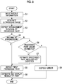
- step S1 needle information, which is information of the puncture needle N1, is input by the user via the input unit 14.
- the needle information input here includes the predetermined distance K from the needle tip part T to the first processed part P1.
- an ultrasound beam is applied from the ultrasound probe 2 in contact with the body surface B of the subject toward the puncture needle N1 in the subject, and an ultrasound image is captured.
- ultrasound echoes from the subject and the puncture needle N1 are received by the transducer array 2A of the ultrasound probe 2 to generate a reception signal, and the generated reception signal is amplified by the amplification unit 17 of the reception unit 4, and A/D conversion is performed by the A/D conversion unit 18. Further, the reception signal subjected to the A/D conversion is output to the image generation unit 5, and the image generation unit 5 generates an ultrasound image based on the reception signal.
- step S3 the arrangement interval detection unit 9 recognizes the plurality of processed parts P1 to P7 of the puncture needle N1 and detects the arrangement intervals of the plurality of processed parts P1 to P7 by image analysis of the ultrasound image generated in step S2.
- step S4 the arithmetic progression determination unit 10 determines whether or not the plurality of arrangement intervals detected in step S3 form an arithmetic progression. In a case where determination is made in step S4 that the plurality of arrangement intervals form an arithmetic progression, the process proceeds to step S5.
- step S5 the first processed part detection unit 11 calculates the tolerance of the arithmetic progression from the plurality of arrangement intervals detected in step S3, and specifies an arrangement interval equal to or less than the calculated tolerance as the arrangement interval L1 between the first processed part P1 and the second processed part P2 to detect the first processed part P1.
- a length obtained by subtracting the tolerance from the arrangement interval on the base end side of the puncture needle N1 is equal to a length of the arrangement interval adjacent to the needle tip part T side of the puncture needle N1.
- the first processed part detection unit 11 can detect the first processed part P1 by specifying the arrangement interval equal to or less than the tolerance as the arrangement interval L1.
- step S4 determines in step S4 that the arithmetic progression is not formed.
- a part of the plurality of processed parts P1 to P7 of the puncture needle N1 may not be depicted, such as any one of the plurality of processed parts P1 to P7 being concealed or disappearing in the ultrasound image.
- the puncture needle N1 according to Embodiment 1 of the present invention is inserted into the subject, even though a part of the plurality of processed parts P1 to P7 of the puncture needle N1 is not depicted in the ultrasound image, it may be possible to estimate the processed part which is not depicted.
- the arrangement interval L1 between the first processed part P1 and the second processed part P2, the arrangement interval L2 between the second processed part P2 and the third processed part P3, an arrangement interval L35 between the third processed part P3 and the fifth processed part P5, the arrangement interval L5 between the fifth processed part P5 and the sixth processed part P6, and the arrangement interval L6 between the sixth processed part P6 and the seventh processed part P7 are detected in step S3.
- a tolerance can be calculated by a difference between the arrangement interval L1 and the arrangement interval L2 among the three consecutive processed parts P1, P2, and P3 and a difference between the arrangement interval L5 and the arrangement interval L6 among the three consecutive processed parts P5, P6, and P7. Further, according to the calculated tolerance, it is estimated that the arrangement interval L35 between the third processed part P3 and the fifth processed part P5 is a sum of the arrangement interval L3 between the third processed part P3 and the fourth processed part P4 and the arrangement interval L4 between the fourth processed part P4 and the fifth processed part P5.
- the estimated arrangement intervals L3 and L4 and the arrangement intervals L1, L2, L5, and L6 estimated in step S3 form an arithmetic progression, and thus, the processed part P4 which is not depicted in the ultrasound image can be estimated with high accuracy.
- the arrangement interval L1 between the first processed part P1 and the second processed part P2 an arrangement interval L25 between the second processed part P2 and the fifth processed part P5, the arrangement interval L5 between the fifth processed part P5 and the sixth processed part P6, and the arrangement interval L6 between the sixth processed part P6 and the seventh processed part P7 are detected in step S3.
- the arrangement interval L5 and the arrangement interval L6 among the three consecutive processed parts P5, P6, and P7 are detected in step S3, a tolerance can be calculated by a difference between the arrangement interval L5 and the arrangement interval L6. Further, according to the calculated tolerance, it is estimated that the arrangement interval L25 between the second processed part P2 and the fifth processed part P5 is a sum of the arrangement interval L2 between the second processed part P2 and the third processed part P3, the arrangement interval L3 between the third processed part P3 and the fourth processed part P4, and the arrangement interval L4 between the fourth processed part P4 and the fifth processed part P5.
- the estimated arrangement intervals L2, L3, and L4 and the arrangement intervals L1, L5, and L6 estimated in step S3 form an arithmetic progression, and thus, the third processed part P3 and the fourth processed part P4 which are not depicted in the ultrasound image can be estimated with high accuracy.
- step S6 the arithmetic progression determination unit 10 determines whether or not the processed part which is not depicted in the ultrasound image can be estimated. In a case where determination is made in step S6 that the processed part which is not depicted in the ultrasound image can be estimated, the process proceeds to step S7.
- step S7 the first processed part detection unit 11 calculates the tolerance of the arithmetic progression from the plurality of arrangement intervals detected in step S3, and estimates the processed part which is not depicted in the ultrasound image using the calculated tolerance. In this way, in a case where the processed part which is not depicted in the ultrasound image is estimated, the process proceeds to step S5.
- step S5 the first processed part detection unit 11 detects the first processed part P1 by specifying an arrangement interval equal to less than the tolerance calculated in step S7 as the arrangement interval L1 between the first processed part P1 and the second processed part P2 among the arrangement intervals of the plurality of processed parts P1 to P7 while taking into consideration a position of the processed part estimated in step S7. In this way, in a case where the first processed part P1 is detected, the process proceeds to step S8.
- the needle tip part position estimation unit 12 estimates, as a position of the needle tip part T, a point extending from the first processed part P1 detected in step S5 to a tip side of the shaft part S by a predetermined distance K along the arrangement direction of the plurality of processed parts P1 to P7, that is, the length direction of the shaft part S of the puncture needle N1. Further, the needle tip part position estimation unit 12 superimposes the estimated position of the needle tip part T on the ultrasound image generated in step S2 and causes the display unit 7 to display the image. For example, as shown in Fig.
- the needle tip part position estimation unit 12 superimposes a tip mark M representing the position of the needle tip part T of the puncture needle N1 on an ultrasound image U and displays the image on the display unit 7.
- the tip mark M is indicated by a black circle for description.
- step S8 In a case where the process of step S8 is completed in this way, the operation of the ultrasound diagnostic apparatus 1 ends.
- step S6 in a case where the arithmetic progression determination unit 10 determines that the plurality of arrangement intervals detected in step S3 are not allowed to form an arithmetic progression and that a processed part which is not depicted in the ultrasound image U cannot be estimated, the process proceeds to step S9.
- the plurality of arrangement intervals detected in step S3 are not allowed to form an arithmetic progression.
- step S9 the arithmetic progression determination unit 10 displays, although not shown, occurrence of an error on the display unit 7. In this way, in a case where the process of step S9 is completed, the operation of the ultrasound diagnostic apparatus 1 ends.
- the puncture needle N1 according to Embodiment 1 of the present invention comprises the plurality of processed parts P1 to P7 forming an arithmetic progression in which values gradually decrease toward the needle tip part T, a distance between the needle tip part T and the first processed part P1 is a predetermined distance K, and the arrangement interval between the first processed part P1 and the second processed part P2 is equal to or less than the tolerance of the arithmetic progression. Therefore, for example, the ultrasound diagnostic apparatus 1 easily estimates the position of the needle tip part T and displays the estimated position of the needle tip part T on the display unit 7. Thus, the user can accurately grasp the position of the needle tip part T of the puncture needle N1 by confirming the display unit 7.
- the ultrasound diagnostic apparatus 1 since the plurality of processed parts P1 to P7 are recognized to detect the arrangement intervals of the plurality of processed parts P1 to P7 by image analysis of the ultrasound image U, whether or not the detected plurality of arrangement intervals form an arithmetic progression is determined, a tolerance of the arithmetic progression is calculated, the first processed part P1 is detected based on the calculated tolerance, and the position of the needle tip part T is estimated based on the position of the detected first processed part P1, the position of the needle tip part T can be estimated with high accuracy.
- the ultrasound diagnostic apparatus 1 even in a case where any one of the plurality of processed parts P1 to P7 of the puncture needle N1 is concealed or disappears in the ultrasound image U due to a high-intensity reflection signal, an acoustic shadow, or the like derived from the tissue in the subject, the first processed part detection unit 11 estimates a position of the concealed or disappearing processed part. Therefore, the position of the needle tip part T can be estimated with high accuracy.
- the number of processed parts is not limited to seven.
- the number of processed parts formed in the shaft part S may be more than seven, and for example, a plurality of processed parts (not shown) forming an arithmetic progression together with the processed parts P1 to P7 may be provided on the base end part side from the processed part P7.
- the number of processed parts may be less than seven, and may be, for example, six or five.
- a length of the predetermined distance K is not particularly limited.
- the shorter the predetermined distance K that is, the closer the first processed part P1 is formed to the needle tip part T, the less likely it is to be affected by deflection of the puncture needle N1 or the like in a case where the position of the needle tip part T is estimated based on the position of the first processed part P1. Therefore, estimation accuracy of the needle tip part T can be improved. Therefore, from the viewpoint of improving the estimation accuracy of the needle tip part T, the length of the predetermined distance K is preferably shorter, for example, the arrangement interval L1 between the first processed part P1 and the second processed part P2 or less.
- the ultrasound diagnostic apparatus 1 comprises a needle information acquisition unit that acquires needle information of the puncture needle N1 by scanning the puncture needle N1, reading a bar code attached to a packaging bag of the puncture needle N1, or the like.
- the user can save time and effort of manually inputting the needle information via the input unit 14.
- the arithmetic progression is formed by the arrangement intervals of the plurality of processed parts P1 to P7, but the arithmetic progression may be formed by the distance from the needle tip part to the first processed part P1 and the arrangement intervals of the plurality of processed parts P1 to P7.
- a puncture needle N2 according to Embodiment 2 of the present invention similarly to the puncture needle N1 of Embodiment 1 shown in Fig. 1 , comprises a shaft part S and a needle tip part T disposed at a tip of the shaft part S, and a plurality of processed parts P1 to P5 are arranged and formed on the shaft part S, a distance L0 from the needle tip part T to the first processed part P1 and arrangement intervals L1 to L4 of the plurality of processed parts P1 to P5 form an arithmetic progression in which values gradually decrease toward the needle tip part T.
- a difference between the distance L0 from the needle tip part T to the first processed part P1 and the arrangement interval L1 between the first processed part P1 and the second processed part P2 and a difference between arrangement intervals adjacent to each other in the arrangement intervals L1 to L4 are a tolerance of the arithmetic progression and each have the same value.
- the distance L0 from the needle tip part T to the first processed part P1 is set so as to be equal to or less than the tolerance of the arithmetic progression and equal to a difference between the arrangement interval L1 between the first processed part P1 and the second processed part P2 and the tolerance of the arithmetic progression.
- a position of the needle tip part T can be estimated by acquiring the tolerance of the arithmetic progression, the arrangement interval L1 between the first processed part P1 and the second processed part P2, and the position of the first processed part P1.
- step S2 as in the aspect shown in Fig. 2 , an ultrasound beam is applied from the ultrasound probe 2 in contact with the body surface B of the subject toward the puncture needle N2 in the subject, and an ultrasound image U is captured.
- step S3 the arrangement interval detection unit 9 recognizes the plurality of processed parts P1 to P5 of the puncture needle N2 and detects the arrangement intervals of the plurality of processed parts P1 to P5 by image analysis of the ultrasound image U generated in step S2.
- step S4 the arithmetic progression determination unit 10 determines whether or not the plurality of arrangement intervals detected in step S3 form an arithmetic progression. In a case where determination is made in step S4 that the plurality of arrangement intervals form an arithmetic progression, the process proceeds to step S5.
- step S5 the first processed part detection unit 11 calculates the tolerance of the arithmetic progression from the plurality of arrangement intervals detected in step S3, and specifies an arrangement interval which is larger than the calculated tolerance and equal to or less than twice the calculated tolerance as the arrangement interval L1 between the first processed part P1 and the second processed part P2 to detect the first processed part P1.
- an arrangement interval adjacent to the needle tip part T side of the puncture needle N2 from the detected arrangement interval is equal to or less than the tolerance, and thus it is equal to the distance L0 from the needle tip part T of the puncture needle N2 to the first processed part P1. Therefore, it is understood that an arrangement interval which is more than the tolerance and equal to or less than twice the tolerance is the arrangement interval L1 between the first processed part P1 closest to the needle tip part T and the second processed part P2 which is second closest to the needle tip part T. That is, the first processed part detection unit 11 can specify an arrangement interval which is more than the tolerance and equal to or less than twice the tolerance as the arrangement interval L1, and thereby, the first processed part P1 can be detected.
- step S8 In a case where the first processed part P1 is detected in this way, the process proceeds to step S8.
- step S4 determines whether the arithmetic progression is not formed by the plurality of arrangement intervals detected in step S3 or not formed by the plurality of arrangement intervals detected in step S3.
- step S6 the arithmetic progression determination unit 10 determines whether or not the processed part which is not depicted in the ultrasound image U can be estimated. In a case where determination is made in step S6 that the processed part which is not depicted on the ultrasound image U can be estimated, the process proceeds to step S7.
- step S7 the first processed part detection unit 11 calculates the tolerance of the arithmetic progression from the plurality of arrangement intervals detected in step S3, and estimates the processed part which is not depicted in the ultrasound image using the calculated tolerance. In a case where the processed part which is not depicted in the ultrasound image U is estimated in this way, the process proceeds to step S5.
- step S5 the first processed part detection unit 11 detects the first processed part P1 by specifying an arrangement interval in which a value obtained by subtracting the tolerance calculated in step S7 from the arrangement interval is equal to or less than the tolerance as the arrangement interval L1 between the first processed part P1 and the second processed part P2 among the arrangement intervals of the plurality of processed parts P1 to P5 while taking into consideration the processed part estimated in step S7.
- the needle tip part position estimation unit 12 estimates, as a position of the needle tip part T, a point extending from the first processed part P1 detected in step S5 to a tip side of the shaft part S by a difference between the arrangement interval L1 between the first processed part P1 and the second processed part and the tolerance calculated in step S6 along the arrangement direction of the plurality of processed parts P1 to P5, that is, the length direction of the shaft part S of the puncture needle N2. Further, as in the aspect shown in Fig. 9 , the needle tip part position estimation unit 12 superimposes a tip mark M representing the estimated position of the needle tip part T on the ultrasound image U generated in step S2 and displays the image on the display unit 7.
- step S8 In a case where the process of step S8 is completed in this way, the operation of the ultrasound diagnostic apparatus 1 ends.
- step S6 in a case where the arithmetic progression determination unit 10 determines that the plurality of arrangement intervals detected in step S3 are not allowed to form an arithmetic progression and that a processed part which is not depicted in the ultrasound image U cannot be estimated, the process proceeds to step S9.
- step S9 the arithmetic progression determination unit 10 displays, although not shown, occurrence of an error on the display unit 7. In this way, in a case where the process of step S9 is completed, the operation of the ultrasound diagnostic apparatus 1 ends.
- the puncture needle N2 according to Embodiment 2 of the present invention comprises the plurality of processed parts P1 to P5 forming an arithmetic progression in which values gradually decrease toward the needle tip part T, a distance K between the needle tip part T and the first processed part P1 is equal to or less than the tolerance of the arithmetic progression and equal to the difference between the arrangement interval between the first processed part P1 and the second processed part P2 and the tolerance. Therefore, the position of the needle tip part T is easily estimated by the ultrasound diagnostic apparatus 1 and displayed on the display unit 7. Thus, the user can accurately grasp the position of the needle tip part T of the puncture needle N2 as in the case of using the puncture needle N1 of Embodiment 1.
- the ultrasound diagnostic apparatus 1 has a configuration in which the ultrasound probe 2 and the display unit 7 are directly connected to the processor 16, but for example, the ultrasound probe 2, the display unit 7, and the processor 16 can be indirectly connected to one another via a network.
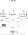
- an ultrasound diagnostic apparatus 1A in an ultrasound diagnostic apparatus 1A according to Embodiment 3, the ultrasound probe 2, the display unit 7, and the input unit 14 are connected to a diagnostic apparatus main body A via a network NW
- the diagnostic apparatus main body A is the ultrasound diagnostic apparatus 1 shown in Fig. 3 , excluding the ultrasound probe 2, the display unit 7, and the input unit 14.
- an ultrasound echo reflected in the inside of the subject is received by the transducer array 2A of the ultrasound probe 2 to generate a reception signal.
- the ultrasound probe 2 transmits the generated reception signal to the diagnostic apparatus main body A via the network NW.
- the reception signal transmitted from the ultrasound probe 2 in this way is received by the image acquisition unit 8 of the processor 16 of the diagnostic apparatus main body A via the network NW, and the image acquisition unit 8 generates the ultrasound image U based on the reception signal.
- the ultrasound image U generated by the image acquisition unit 8 is sent to the display control unit 6 and the arrangement interval detection unit 9.
- the display control unit 6 performs predetermined processing on the ultrasound image U received from the image acquisition unit 8, and further, transmits the ultrasound image U subjected to the predetermined processing to the display unit 7 via the network NW In this way, the ultrasound image U transmitted from the display control unit 6 of the processor 16 of the diagnostic apparatus main body A is received by the display unit 7 via the network NW and displayed on the display unit 7.
- the arrangement interval detection unit 9 recognizes the plurality of processed parts P1 to P7 of the puncture needle N1 and detects the arrangement intervals of the recognized plurality of processed parts P1 to P7 by image analysis of the ultrasound image U received from the image acquisition unit 8.
- the arithmetic progression determination unit 10 determines whether or not the plurality of arrangement intervals detected by the arrangement interval detection unit 9 form an arithmetic progression, and the first processed part detection unit 11 detects the first processed part P1 of the puncture needle N1 based on a determination result by the arithmetic progression determination unit 10.
- the needle tip part position estimation unit 12 estimates the position of the needle tip part T of the puncture needle N1 based on the position of the first processed part P1 detected by the first processed part detection unit 11 and the needle information input by the user via the input unit 14 and transmitted to the processor 16 of the diagnostic apparatus main body A via the network NW Further, the needle tip part position estimation unit 12 superimposes information about the estimated position of the needle tip part T1 on the ultrasound image U and transmits the image to the display unit 7 via the network NW Thus, the estimated position of the needle tip part T1 is displayed on the display unit 7.
- the plurality of processed parts P1 to P7 are recognized to detect the arrangement intervals of the plurality of processed parts P1 to P7 by image analysis of the ultrasound image U, whether or not the detected plurality of arrangement intervals form an arithmetic progression is determined, a tolerance of the arithmetic progression is calculated, the first processed part P1 is detected based on the calculated tolerance, and the position of the needle tip part T is estimated based on the position of the detected first processed part P1. Therefore, the position of the needle tip part T can be estimated with high accuracy.
- the diagnostic apparatus main body A can be used as a so-called remote server.
- the user can perform ultrasound diagnosis of the subject by preparing only the ultrasound probe 2, the display unit 7, and the input unit 14 at the user's hand, and thus convenience in the ultrasound diagnosis can be improved.
- the user can more easily perform the ultrasound diagnosis of the subject, and convenience in the ultrasound diagnosis can be further improved.
- the ultrasound probe 2, the display unit 7, and the input unit 14 are connected to the diagnostic apparatus main body A via the network NW
- the ultrasound probe 2, the display unit 7, the input unit 14, and the diagnostic apparatus main body A may be wire-connected or wirelessly connected to the network NW
- Embodiment 3 Although it has been described that the aspect of Embodiment 3 is applied to Embodiment 1, the same can be applied to Embodiment 2.
Landscapes
- Health & Medical Sciences (AREA)
- Life Sciences & Earth Sciences (AREA)
- Engineering & Computer Science (AREA)
- Medical Informatics (AREA)
- Surgery (AREA)
- Pathology (AREA)
- Veterinary Medicine (AREA)
- Public Health (AREA)
- Biomedical Technology (AREA)
- Heart & Thoracic Surgery (AREA)
- General Health & Medical Sciences (AREA)
- Molecular Biology (AREA)
- Animal Behavior & Ethology (AREA)
- Nuclear Medicine, Radiotherapy & Molecular Imaging (AREA)
- Physics & Mathematics (AREA)
- Biophysics (AREA)
- Radiology & Medical Imaging (AREA)
- Computer Vision & Pattern Recognition (AREA)
- Physiology (AREA)
- Gynecology & Obstetrics (AREA)
- Ultra Sonic Daignosis Equipment (AREA)
Abstract
Description
- The present invention relates to a puncture needle, an ultrasound diagnostic apparatus that detects a puncture needle inserted into a subject, and a control method of the ultrasound diagnostic apparatus.
- There is a technique of inserting a so-called puncture needle into a subject in order to place a catheter in the subject. In recent years, a method of inserting a puncture needle into a subject while observing the puncture needle inserted into the subject using an ultrasound diagnostic apparatus is often used.
- In general, the ultrasound diagnostic apparatus comprises an ultrasound probe provided with a transducer array in which a plurality of elements are arranged. In a state where the ultrasound probe is brought into contact with a body surface of the subject, an ultrasound beam is transmitted from the transducer array toward an inside of the subject, and an ultrasound echo from the subject is received by the transducer array to obtain element data. Further, the ultrasound diagnostic apparatus electrically processes the obtained element data to generate an ultrasound image for a relevant part of the subject.
- Here, since the puncture needle is usually inserted in an inclined state with respect to the body surface of the subject, the ultrasound echo reflected from the puncture needle in the subject is difficult to propagate toward the ultrasound probe, and the puncture needle is sometimes not clearly depicted in the ultrasound image. Therefore, in order to clearly depict the puncture needle in the ultrasound image, for example, as disclosed in
JP2011-125632A JP2011-125632A JP2011-125632A JP5635462B - However, since a groove cannot be formed at a tip part of a sharply pointed puncture needle, a user such as a doctor cannot clearly grasp the tip part of the puncture needle even by observing an ultrasound image depicting a plurality of grooves of the puncture needle, and therefore, it is sometimes difficult to guide the tip part of the puncture needle to a desired place.
- In addition, the groove of the puncture needle on the ultrasound image is sometimes concealed or disappears due to a high-intensity reflection signal, an acoustic shadow, or the like derived from a tissue in a subject. Thus, a position of the groove in the puncture needle is not specified, and it is sometimes difficult for the user to estimate a position of the tip part of the puncture needle. In addition, in a case where the light absorbing portion is provided on the part of the surface of the puncture needle as in
JP5635462B - The present invention has been made to solve such a conventional problem, and an object of the present invention is to provide a puncture needle, an ultrasound diagnostic apparatus, and a control method of the ultrasound diagnostic apparatus, with which a user can accurately grasp a tip part of the puncture needle.
- In order to achieve the above object, a puncture needle according to a first aspect of the present invention comprises a shaft part, a needle tip part disposed at a tip of the shaft part, and a plurality of processed parts that are arranged on an outer peripheral part of the shaft part along a length direction of the shaft part and form an arithmetic progression in which arrangement intervals gradually decrease toward the needle tip part, in which among the plurality of processed parts, an arrangement interval between a first processed part which is separated from the needle tip part by a predetermined distance and is closest to the needle tip part and a second processed part which is second closest to the needle tip part is equal to or less than a tolerance of the arithmetic progression, or a distance from the needle tip part to the first processed part which is closest to the needle tip part is equal to or less than the tolerance of the arithmetic progression and equal to a difference between the arrangement interval between the first processed part and the second processed part which is second closest to the needle tip part and the tolerance.
- It is preferable that the plurality of processed parts are grooves formed to surround a periphery of the shaft part.
- An ultrasound diagnostic apparatus according to a second aspect of the present invention comprises a display unit that displays an ultrasound image in which the puncture needle is captured, an arrangement interval detection unit that recognizes the plurality of processed parts of the puncture needle and detects the arrangement intervals of the plurality of processed parts by image analysis of the ultrasound image, an arithmetic progression determination unit that determines whether or not the arrangement intervals of the plurality of processed parts detected by the arrangement interval detection unit form the arithmetic progression, a first processed part detection unit that calculates the tolerance of the arithmetic progression and detects the first processed part which is closest to the needle tip part among the plurality of processed parts based on the tolerance in a case where the arithmetic progression determination unit determines that the arithmetic progression is formed, and a needle tip part position estimation unit that estimates a position of the needle tip part based on a position of the first processed part detected by the first processed part detection unit.
- Here, the needle tip part position estimation unit may estimate a point extending from the first processed part to a tip side of the shaft part by the predetermined distance as the position of the needle tip part in a case where the arrangement interval between the first processed part and the second processed part of the puncture needle is equal to or less than the tolerance of the arithmetic progression, and estimate a point extending from the first processed part to the tip side of the shaft part by the difference between the arrangement interval between the first processed part and the second processed part and the tolerance as the position of the needle tip part in a case where the distance from the needle tip part to the first processed part of the puncture needle is equal to or less than the tolerance of the arithmetic progression and equal to the difference between the arrangement interval between the first processed part and the second processed part and the tolerance.
- In addition, it is preferable that the needle tip part position estimation unit displays the estimated position of the needle tip part on the display unit.
- The ultrasound diagnostic apparatus may further comprise an ultrasound probe and an image acquisition unit that acquires the ultrasound image by performing transmission and reception of an ultrasound beam between the ultrasound probe and a subject. In this case, the display unit may display the ultrasound image acquired by the image acquisition unit, and the arrangement interval detection unit may recognize the plurality of processed parts of the puncture needle and detect the arrangement intervals of the plurality of processed parts by image analysis of the ultrasound image acquired by the image acquisition unit.
- A control method of an ultrasound diagnostic apparatus according to a third aspect of the present invention comprises displaying an ultrasound image in which the puncture needle is captured, recognizing the plurality of processed parts of the puncture needle and detecting the arrangement intervals of the plurality of processed parts by image analysis of the ultrasound image, determining whether or not the detected arrangement intervals of the plurality of processed parts form the arithmetic progression, calculating the tolerance of the arithmetic progression and detecting the first processed part which is closest to the needle tip part among the plurality of processed parts based on the tolerance in a case where determination is made that the arithmetic progression is formed, and estimating a position of the needle tip part based on a position of the detected first processed part.
- According to the present invention, a puncture needle comprises a shaft part, a needle tip part disposed at a tip of the shaft part, and a plurality of processed parts that are arranged on an outer peripheral part of the shaft part along a length direction of the shaft part and form an arithmetic progression in which arrangement intervals gradually decrease toward the needle tip part, in which among the plurality of processed parts, an arrangement interval between a first processed part which is separated from the needle tip part by a predetermined distance and is closest to the needle tip part and a second processed part which is second closest to the needle tip part is equal to or less than a tolerance of the arithmetic progression, or a distance from the needle tip part to the first processed part which is closest to the needle tip part is equal to or less than the tolerance of the arithmetic progression and equal to a difference between the arrangement interval between the first processed part and the second processed part which is second closest to the needle tip part and the tolerance. Therefore, a user can accurately grasp the tip part of the puncture needle.
-
-
Fig. 1 is a diagram showing a puncture needle according to Embodiment 1 of the present invention. -
Fig. 2 is a diagram schematically showing a state where the puncture needle according to Embodiment 1 of the present invention is inserted into a subject and the puncture needle is irradiated with an ultrasound beam. -
Fig. 3 is a block diagram showing a configuration of an ultrasound diagnostic apparatus according to Embodiment 1 of the present invention. -
Fig. 4 is a block diagram showing a configuration of a reception unit in Embodiment 1 of the present invention. -
Fig. 5 is a block diagram showing a configuration of an image generation unit in Embodiment 1 of the present invention. -
Fig. 6 is a flowchart showing an operation of the ultrasound diagnostic apparatus in Embodiment 1 of the present invention. -
Fig. 7 is a diagram schematically showing a state where one processed part is not depicted in an ultrasound image in Embodiment 1 of the present invention. -
Fig. 8 is a diagram schematically showing a state where two processed parts are not depicted in the ultrasound image in Embodiment 1 of the present invention. -
Fig. 9 is a diagram schematically showing a state where a position of a needle tip part is displayed on the ultrasound image in Embodiment 1 of the present invention. -
Fig. 10 is a diagram showing a puncture needle according toEmbodiment 2 of the present invention. -
Fig. 11 is a flowchart showing an operation of an ultrasound diagnostic apparatus according toEmbodiment 2 of the present invention. -
Fig. 12 is a block diagram showing a configuration of an ultrasound diagnostic apparatus according toEmbodiment 3 of the present invention. - Hereinafter, embodiments of the present invention will be described with reference to the accompanying drawings.
- Description of constituents described below may be made based on a typical embodiment of the present invention, but the present invention is not limited to such an embodiment.
-
Fig. 1 shows a puncture needle N1 according to Embodiment 1 of the present invention. The puncture needle N1 is inserted into a subject in order to place a catheter, a drug, or the like in the subject, and comprises a shaft part S and a sharp needle tip part T formed by obliquely cutting out a tip part of the shaft part S and disposed at a tip of the shaft part S. In the shaft part S, a plurality of processed parts P1 to P7 formed of grooves formed to surround a periphery of the shaft part S are arranged and formed along a length direction of the shaft part S. In addition, an arrangement interval L1 between the first processed part P1 and the second processed part P2, an arrangement interval L2 between the second processed part P2 and the third processed part P3, an arrangement interval L3 between the third processed part P3 and the fourth processed part P4, an arrangement interval L4 between the fourth processed part P4 and the fifth processed part P5, an arrangement interval L5 between the fifth processed part P5 and the sixth processed part P6, and an arrangement interval L6 between the sixth processed part P6 and the seventh processed part P7 form an arithmetic progression in which values gradually decrease toward the needle tip part T. Here, the term "the arrangement intervals form the arithmetic progression" means that values of the arrangement intervals form the arithmetic progression, and that in a case where values of the arrangement intervals L1 to L6 are integers and are aligned to a specific unit such as mm, the values form the arithmetic progression. Therefore, in the arrangement intervals L1 to L6 of the plurality of processed parts P1 to P7, a difference between arrangement intervals adjacent to each other is a so-called tolerance of the arithmetic progression and each has the same value. - Among the plurality of processed parts P1 to P7, the arrangement interval L1 between the first processed part P1 which is separated from the needle tip part T by a predetermined distance K and is closest to the needle tip part T and the second processed part P2 which is second closest to the needle tip part T is designed to be equal to or less than the tolerance of the arithmetic progression formed by the arrangement intervals of the plurality of processed parts P1 to P7. For example, assuming that the arrangement interval L1 between the first processed part P1 and the second processed part P2 is 5 mm, the arrangement interval L2 between the second processed part P2 and the third processed part P3 is 10 mm, the arrangement interval L3 between the third processed part P3 and the fourth processed part P4 is 15 mm, the arrangement interval L4 between the fourth processed part P4 and the fifth processed part P5 is 20 mm, the arrangement interval L5 between the fifth processed part P5 and the sixth processed part P6 is 25 mm, and the arrangement interval L6 between the sixth processed part P6 and the seventh processed part P7 is 30 mm, the first processed part P1 to the seventh processed part P7 can form an arithmetic progression with a tolerance of 5 mm, and the first processed part P1 to the seventh processed part P7 can be formed such that the arrangement interval L1 between the first processed part P1 and the second processed part P2 is equal to the tolerance of 5 mm.
- In addition, as shown in
Fig. 1 , since the needle tip part T is formed by obliquely cutting out the tip part of the shaft part S, an inclined surface E inclined by a predetermined inclination angle with respect to an extending direction of the shaft part S is formed at a tip part of the shaft part S, and the first processed part P1 is formed on a base end side of the shaft part S from the inclined surface E. Therefore, a formation position of the first processed part P1 can be appropriately set according to the specifications of the puncture needle N1, such as an outer diameter of the shaft part S and the inclination angle of the inclined surface E with respect to the extending direction of the shaft part S. - As shown in
Fig. 2 , the puncture needle N1 according to Embodiment 1 of the present invention as described above is irradiated with an ultrasound beam from anultrasound probe 2 in contact with a body surface B of the subject while being inserted into the subject. The ultrasound beam applied to the puncture needle is reflected by the plurality of processed parts P1 to P7, and the reflected ultrasound beam propagates toward theultrasound probe 2. Thus, in a case where the puncture needle N1 is imaged by theultrasound probe 2, a plurality of processed parts P1 to P7 of the puncture needle N1 are depicted in an ultrasound image. - Here, in the puncture needle N1 according to Embodiment 1 of the present invention, since the first processed part P1 is formed on the base end side of the shaft part S from the inclined surface E, the first processed part P1 can be depicted in the ultrasound image regardless of a rotation angle around a central axis of the puncture needle N1.
- Next, an ultrasound diagnostic apparatus 1 according to Embodiment 1 of the present invention will be described. The ultrasound diagnostic apparatus 1 images the puncture needle N1 inserted into the subject. As shown in
Fig. 3 , the ultrasound diagnostic apparatus 1 comprises theultrasound probe 2 incorporating atransducer array 2A, and atransmission unit 3 and areception unit 4 are connected to thetransducer array 2A. Animage generation unit 5, adisplay control unit 6, and adisplay unit 7 are sequentially connected to thereception unit 4. Here, an image acquisition unit 8 is constituted of thetransmission unit 3, thereception unit 4, and theimage generation unit 5. In addition, an arrangementinterval detection unit 9 is connected to theimage generation unit 5, and an arithmeticprogression determination unit 10 and a first processed part detection unit 11 are connected to the arrangementinterval detection unit 9. Thedisplay control unit 6 and the first processed part detection unit 11 are connected to the arithmeticprogression determination unit 10. A needle tip partposition estimation unit 12 is connected to the first processed part detection unit 11, and thedisplay control unit 6 is connected to the needle tip partposition estimation unit 12. - Further, an
apparatus control unit 13 is connected to thedisplay control unit 6, the image acquisition unit 8, the arrangementinterval detection unit 9, the arithmeticprogression determination unit 10, the first processed part detection unit 11, and the needle tip partposition estimation unit 12, and aninput unit 14 and astorage unit 15 are connected to theapparatus control unit 13. Here, theapparatus control unit 13 and thestorage unit 15 are connected to each other so that information can be exchanged in both directions. - In addition, a
processor 16 is constituted of thedisplay control unit 6, the image acquisition unit 8, the arrangementinterval detection unit 9, the arithmeticprogression determination unit 10, the first processed part detection unit 11, the needle tip partposition estimation unit 12, and theapparatus control unit 13. - The
transducer array 2A of theultrasound probe 2 shown inFig. 3 has a plurality of transducers arranged one-dimensionally or two-dimensionally. Each of these transducers transmits an ultrasonic wave in accordance with a drive signal supplied from thetransmission unit 3, and receives an ultrasound echo from the subject to output a reception signal. Each transducer is constituted by forming electrodes on both ends of a piezoelectric body made of, for example, a piezoelectric ceramic represented by lead zirconate titanate (PZT), a polymer piezoelectric element represented by poly vinylidene di fluoride (PMN-PT: polyvinylidene fluoride), and a piezoelectric single crystal represented by lead magnesium niobate-lead titanate (PMN-PT: lead magnesium niobate-lead titanate solid solution). - The
transmission unit 3 of the image acquisition unit 8 includes, for example, a plurality of pulse generators, and based on a transmission delay pattern selected in accordance with a control signal from theapparatus control unit 13, supplies the drive signals to the plurality of transducers by adjusting the delay amount so that the ultrasonic waves transmitted from the plurality of transducers of thetransducer array 2A form an ultrasound beam. In this way, in a case where a pulsed or continuous wave voltage is applied to the electrodes of the plurality of transducers of thetransducer array 2A, the piezoelectric body expands and contracts, pulsed or continuous wave ultrasonic waves are generated from the transducers, and an ultrasound beam is formed from a composite wave of the ultrasonic waves. - The transmitted ultrasound beam is reflected at an object such as a part of the subject and propagates toward the
transducer array 2A of theultrasound probe 2. The ultrasound echo propagating toward thetransducer array 2A in this way is received by each of the transducers constituting thetransducer array 2A. In this case, each transducer constituting thetransducer array 2A expands and contracts by receiving the propagating ultrasound echo to generate an electric signal, and outputs these electric signals to thereception unit 4. - The
reception unit 4 of the image acquisition unit 8 processes a signal output from thetransducer array 2A in accordance with the control signal from theapparatus control unit 13. As shown inFig. 4 , thereception unit 4 has a configuration in which anamplification unit 17 and an analog digital (AD)conversion unit 18 are connected in series. Theamplification unit 17 amplifies the signal received from each of the transducers constituting thetransducer array 2A, and transmits the amplified signal to theAD conversion unit 18. TheAD conversion unit 18 converts the signal transmitted from theamplification unit 17 into a digitized reception signal, and sends these pieces of data to theimage generation unit 5 of the image acquisition unit 8. - As shown in
Fig. 5 , theimage generation unit 5 of the image acquisition unit 8 has a configuration in which asignal processing unit 19, a digital scan converter (DSC) 20, and animage processing unit 21 are sequentially connected in series. Thesignal processing unit 19 performs reception focus processing by applying a delay to each piece of data of the reception signal based on a reception delay pattern selected in accordance with the control signal from theapparatus control unit 13, and adding up the results (phase-adjusted addition). By the reception focus processing, a sound ray signal in which a focus of the ultrasound echo is narrowed down to one scanning line is generated. In addition, thesignal processing unit 19 corrects attenuation caused by a propagation distance of the generated sound ray signal according to a depth of a position where the ultrasonic wave is reflected, and then performs envelope detection processing to generate a B-mode image signal representing a tissue in the subject. The B-mode image signal generated in this way is output to theDSC 20. - The
DSC 20 of theimage generation unit 5 generates an ultrasound image by raster-converting the B-mode image signal into an image signal according to a normal television signal scanning method. Theimage processing unit 21 of theimage generation unit 5 performs various kinds of necessary image processing such as brightness correction, gradation correction, sharpness correction, and color correction on the ultrasound image obtained by theDSC 20, and then outputs the ultrasound image to thedisplay control unit 6 and the arrangementinterval detection unit 9. - The arrangement
interval detection unit 9 of theprocessor 16 recognizes the plurality of processed parts P1 to P7 of the puncture needle N1 and detects arrangement intervals of the plurality of processed parts P1 to P7 by image analysis of the ultrasound image in which the puncture needle N1 is captured. - The arithmetic
progression determination unit 10 of theprocessor 16 determines whether or not the arrangement intervals of the plurality of processed parts P1 to P7 detected by the arrangementinterval detection unit 9 form the arithmetic progression. The arithmeticprogression determination unit 10 can determine whether or not the arrangement intervals of the plurality of processed parts P1 to P7 form the arithmetic progression, for example, by determining whether or not a plurality of the arrangement intervals detected by the arrangementinterval detection unit 9 gradually decrease by a certain length in one direction along an arrangement direction of the plurality of processed parts P1 to P7. Even in a case where the actually detected values are, for example, 4.9 mm for the arrangement interval L1, 10.1 mm for the arrangement interval L2, and 14.9 mm for the arrangement interval L3, determination may be made whether or not the arithmetic progression is formed by approximating the values to integer values. - The first processed part detection unit 11 of the
processor 16 detects the first processed part P1 closest to the needle tip part T among the plurality of processed parts P1 to P7 of the puncture needle N1 by using the plurality of arrangement intervals detected by the arrangementinterval detection unit 9 based on a determination result by the arithmeticprogression determination unit 10. In this case, in a case where the arithmeticprogression determination unit 10 determines that the arithmetic progression is formed, the first processed part detection unit 11 calculates the tolerance of the arithmetic progression and detects the first processed part P1 based on the calculated tolerance. - Here, for example, any one of the plurality of processed parts P1 to P7 of the puncture needle N1 may be concealed or disappear in the ultrasound image due to a high-intensity reflection signal, a so-called acoustic shadow, or the like derived from the tissue in the subject. In this case, the arithmetic
progression determination unit 10 determines that the arithmetic progression is not formed, but in this case, the first processed part detection unit 11 estimates the processed part concealed or disappearing due to the high-intensity reflection signal, the acoustic shadow, or the like based on the plurality of arrangement intervals detected by the arrangementinterval detection unit 9, to calculate the tolerance of the arithmetic progression formed by the arrangement intervals of the plurality of processed parts P1 to P7, and detects the first processed part P1 based on the calculated tolerance. - The needle tip part
position estimation unit 12 of theprocessor 16 estimates a position of the needle tip part T based on the position of the first processed part P1 detected by the first processed part detection unit 11, and displays the estimated position of the needle tip part T on thedisplay unit 7. For example, the needle tip partposition estimation unit 12 estimates, as the position of the needle tip part, a point extending from the first processed part P1 to a tip side of the shaft part S by a predetermined distance K along the length direction of the shaft part S, in a case where the arrangement interval L1 between the first processed part P1 and the second processed part P2 of the puncture needle N1, the interval being detected by the arrangementinterval detection unit 9, is equal to or less than the tolerance calculated by the first processed part detection unit 11. - Here, the needle tip part
position estimation unit 12 may use, for example, a value stored in advance as the predetermined distance K, or may use a value input by the user via theinput unit 14. - The
apparatus control unit 13 of theprocessor 16 controls each unit of the ultrasound diagnostic apparatus 1 based on a program recorded in advance in thestorage unit 15 or the like and an input operation by the user via theinput unit 14. - The
display control unit 6 of theprocessor 16, under the control of theapparatus control unit 13, causes thedisplay unit 7 to display the ultrasound image generated by theimage generation unit 5 of the image acquisition unit 8, the position of the needle tip part T estimated by the needle tip partposition estimation unit 12, and the like. - The
display unit 7 of the ultrasound diagnostic apparatus 1 displays the ultrasound image generated by the image acquisition unit 8, the position of the needle tip part T estimated by the needle tip partposition estimation unit 12, and the like, and includes, for example, a display device such as a liquid crystal display (LCD) or an organic EL display (organic electroluminescence display). - The
input unit 14 of the ultrasound diagnostic apparatus 1 is for the user to perform an input operation, and may comprise a keyboard, a mouse, a trackball, a touch pad, a touch panel, and the like. - The
storage unit 15 stores an operation program or the like of the ultrasound diagnostic apparatus 1, and may use a recording medium such as a flash memory, a hard disc drive (HDD), a solid state drive (SSD),a flexible disc (FD), a magneto-optical disc (MO disc), a magnetic tape (MT), a random access memory (RAM), a compact disc (CD), a digital versatile disc (DVD), a secure digital card (SD card), and a universal serial bus memory (USB memory), or a server. - The
processor 16 having thedisplay control unit 6, the image acquisition unit 8, the arrangementinterval detection unit 9, the arithmeticprogression determination unit 10, the first processed part detection unit 11, the needle tip partposition estimation unit 12, and theapparatus control unit 13 is constituted of a central processing unit (CPU) and a control program for causing the CPU to perform various kinds of processing, and may be constituted of a field programmable gate array (FPGA), a digital signal processor (DSP), an application specific integrated circuit (ASIC), a graphics processing unit (GPU), or other integrated circuit (IC) or a combination thereof. - The
display control unit 6, the image acquisition unit 8, the arrangementinterval detection unit 9, the arithmeticprogression determination unit 10, the first processed part detection unit 11, the needle tip partposition estimation unit 12, and theapparatus control unit 13 of theprocessor 16 may be partially or entirely integrated into one CPU or the like. - Next, the operation of the ultrasound diagnostic apparatus 1 in Embodiment 1 will be described in detail with reference to the flowchart shown in
Fig. 6 . - First, in step S1, needle information, which is information of the puncture needle N1, is input by the user via the
input unit 14. The needle information input here includes the predetermined distance K from the needle tip part T to the first processed part P1. - In the following step S2, as shown in
Fig. 2 , an ultrasound beam is applied from theultrasound probe 2 in contact with the body surface B of the subject toward the puncture needle N1 in the subject, and an ultrasound image is captured. In this case, ultrasound echoes from the subject and the puncture needle N1 are received by thetransducer array 2A of theultrasound probe 2 to generate a reception signal, and the generated reception signal is amplified by theamplification unit 17 of thereception unit 4, and A/D conversion is performed by the A/D conversion unit 18. Further, the reception signal subjected to the A/D conversion is output to theimage generation unit 5, and theimage generation unit 5 generates an ultrasound image based on the reception signal. - In step S3, the arrangement
interval detection unit 9 recognizes the plurality of processed parts P1 to P7 of the puncture needle N1 and detects the arrangement intervals of the plurality of processed parts P1 to P7 by image analysis of the ultrasound image generated in step S2. - In step S4, the arithmetic
progression determination unit 10 determines whether or not the plurality of arrangement intervals detected in step S3 form an arithmetic progression. In a case where determination is made in step S4 that the plurality of arrangement intervals form an arithmetic progression, the process proceeds to step S5. - In step S5, the first processed part detection unit 11 calculates the tolerance of the arithmetic progression from the plurality of arrangement intervals detected in step S3, and specifies an arrangement interval equal to or less than the calculated tolerance as the arrangement interval L1 between the first processed part P1 and the second processed part P2 to detect the first processed part P1.
- Here, since the plurality of arrangement intervals detected in step S3 are arranged so as to form the arithmetic progression along the arrangement direction of the plurality of processed parts P1 to P7 depicted in the ultrasound image, a length obtained by subtracting the tolerance from the arrangement interval on the base end side of the puncture needle N1 is equal to a length of the arrangement interval adjacent to the needle tip part T side of the puncture needle N1. Therefore, in a case where an arrangement interval having a length equal to or less than the tolerance is detected, there is no arrangement interval adjacent to the needle tip part T side of the puncture needle N1 from the detected arrangement interval, and it is understood that the arrangement interval having a length equal to or less than the tolerance is the arrangement interval L1 between the first processed part P1 closest to the needle tip part T and the second processed part P2 which is second closest to the needle tip part T. That is, the first processed part detection unit 11 can detect the first processed part P1 by specifying the arrangement interval equal to or less than the tolerance as the arrangement interval L1.
- In a case where the arithmetic
progression determination unit 10 determines in step S4 that the arithmetic progression is not formed, the process proceeds to step S6. - Here, for example, due to a high-intensity reflection signal, a so-called acoustic shadow, or the like derived from the tissue in the subject, a part of the plurality of processed parts P1 to P7 of the puncture needle N1 may not be depicted, such as any one of the plurality of processed parts P1 to P7 being concealed or disappearing in the ultrasound image. In a case where the puncture needle N1 according to Embodiment 1 of the present invention is inserted into the subject, even though a part of the plurality of processed parts P1 to P7 of the puncture needle N1 is not depicted in the ultrasound image, it may be possible to estimate the processed part which is not depicted.
- For example, as shown in
Fig. 7 , in a case where the fourth processed part P4 among the plurality of processed parts P1 to P7 is not depicted in the ultrasound image, the arrangement interval L1 between the first processed part P1 and the second processed part P2, the arrangement interval L2 between the second processed part P2 and the third processed part P3, an arrangement interval L35 between the third processed part P3 and the fifth processed part P5, the arrangement interval L5 between the fifth processed part P5 and the sixth processed part P6, and the arrangement interval L6 between the sixth processed part P6 and the seventh processed part P7 are detected in step S3. In this case, a tolerance can be calculated by a difference between the arrangement interval L1 and the arrangement interval L2 among the three consecutive processed parts P1, P2, and P3 and a difference between the arrangement interval L5 and the arrangement interval L6 among the three consecutive processed parts P5, P6, and P7. Further, according to the calculated tolerance, it is estimated that the arrangement interval L35 between the third processed part P3 and the fifth processed part P5 is a sum of the arrangement interval L3 between the third processed part P3 and the fourth processed part P4 and the arrangement interval L4 between the fourth processed part P4 and the fifth processed part P5. Finally, it is confirmed that the estimated arrangement intervals L3 and L4 and the arrangement intervals L1, L2, L5, and L6 estimated in step S3 form an arithmetic progression, and thus, the processed part P4 which is not depicted in the ultrasound image can be estimated with high accuracy. - In addition, for example, as shown in
Fig. 8 , in a case where the third processed part P3 and the fourth processed part P4 among the plurality of processed parts P1 to P7 are not depicted in the ultrasound image, the arrangement interval L1 between the first processed part P1 and the second processed part P2, an arrangement interval L25 between the second processed part P2 and the fifth processed part P5, the arrangement interval L5 between the fifth processed part P5 and the sixth processed part P6, and the arrangement interval L6 between the sixth processed part P6 and the seventh processed part P7 are detected in step S3. In this case, since the arrangement interval L5 and the arrangement interval L6 among the three consecutive processed parts P5, P6, and P7 are detected in step S3, a tolerance can be calculated by a difference between the arrangement interval L5 and the arrangement interval L6. Further, according to the calculated tolerance, it is estimated that the arrangement interval L25 between the second processed part P2 and the fifth processed part P5 is a sum of the arrangement interval L2 between the second processed part P2 and the third processed part P3, the arrangement interval L3 between the third processed part P3 and the fourth processed part P4, and the arrangement interval L4 between the fourth processed part P4 and the fifth processed part P5. Finally, it is confirmed that the estimated arrangement intervals L2, L3, and L4 and the arrangement intervals L1, L5, and L6 estimated in step S3 form an arithmetic progression, and thus, the third processed part P3 and the fourth processed part P4 which are not depicted in the ultrasound image can be estimated with high accuracy. - Therefore, in step S6, the arithmetic
progression determination unit 10 determines whether or not the processed part which is not depicted in the ultrasound image can be estimated. In a case where determination is made in step S6 that the processed part which is not depicted in the ultrasound image can be estimated, the process proceeds to step S7. - In step S7, the first processed part detection unit 11 calculates the tolerance of the arithmetic progression from the plurality of arrangement intervals detected in step S3, and estimates the processed part which is not depicted in the ultrasound image using the calculated tolerance. In this way, in a case where the processed part which is not depicted in the ultrasound image is estimated, the process proceeds to step S5.
- In step S5, the first processed part detection unit 11 detects the first processed part P1 by specifying an arrangement interval equal to less than the tolerance calculated in step S7 as the arrangement interval L1 between the first processed part P1 and the second processed part P2 among the arrangement intervals of the plurality of processed parts P1 to P7 while taking into consideration a position of the processed part estimated in step S7. In this way, in a case where the first processed part P1 is detected, the process proceeds to step S8.
- In step S8, the needle tip part
position estimation unit 12 estimates, as a position of the needle tip part T, a point extending from the first processed part P1 detected in step S5 to a tip side of the shaft part S by a predetermined distance K along the arrangement direction of the plurality of processed parts P1 to P7, that is, the length direction of the shaft part S of the puncture needle N1. Further, the needle tip partposition estimation unit 12 superimposes the estimated position of the needle tip part T on the ultrasound image generated in step S2 and causes thedisplay unit 7 to display the image. For example, as shown inFig. 9 , the needle tip partposition estimation unit 12 superimposes a tip mark M representing the position of the needle tip part T of the puncture needle N1 on an ultrasound image U and displays the image on thedisplay unit 7. In the example shown inFig. 9 , the tip mark M is indicated by a black circle for description. - In a case where the process of step S8 is completed in this way, the operation of the ultrasound diagnostic apparatus 1 ends.
- In addition, in step S6, in a case where the arithmetic
progression determination unit 10 determines that the plurality of arrangement intervals detected in step S3 are not allowed to form an arithmetic progression and that a processed part which is not depicted in the ultrasound image U cannot be estimated, the process proceeds to step S9. Here, for example, in a case where three consecutive processed parts among the plurality of processed parts P1 to P7 are not depicted in the ultrasound image U and a tolerance cannot be calculated, or in a case where a puncture needle having no processed parts arranged in accordance with an arithmetic progression is inserted into the subject, instead of the puncture needle N1 according to Embodiment 1 of the present invention, the plurality of arrangement intervals detected in step S3 are not allowed to form an arithmetic progression. - In step S9, the arithmetic
progression determination unit 10 displays, although not shown, occurrence of an error on thedisplay unit 7. In this way, in a case where the process of step S9 is completed, the operation of the ultrasound diagnostic apparatus 1 ends. - As described above, the puncture needle N1 according to Embodiment 1 of the present invention comprises the plurality of processed parts P1 to P7 forming an arithmetic progression in which values gradually decrease toward the needle tip part T, a distance between the needle tip part T and the first processed part P1 is a predetermined distance K, and the arrangement interval between the first processed part P1 and the second processed part P2 is equal to or less than the tolerance of the arithmetic progression. Therefore, for example, the ultrasound diagnostic apparatus 1 easily estimates the position of the needle tip part T and displays the estimated position of the needle tip part T on the
display unit 7. Thus, the user can accurately grasp the position of the needle tip part T of the puncture needle N1 by confirming thedisplay unit 7. - According to the ultrasound diagnostic apparatus 1 according to Embodiment 1 of the present invention, since the plurality of processed parts P1 to P7 are recognized to detect the arrangement intervals of the plurality of processed parts P1 to P7 by image analysis of the ultrasound image U, whether or not the detected plurality of arrangement intervals form an arithmetic progression is determined, a tolerance of the arithmetic progression is calculated, the first processed part P1 is detected based on the calculated tolerance, and the position of the needle tip part T is estimated based on the position of the detected first processed part P1, the position of the needle tip part T can be estimated with high accuracy.
- Further, according to the ultrasound diagnostic apparatus 1 according to Embodiment 1 of the present invention, even in a case where any one of the plurality of processed parts P1 to P7 of the puncture needle N1 is concealed or disappears in the ultrasound image U due to a high-intensity reflection signal, an acoustic shadow, or the like derived from the tissue in the subject, the first processed part detection unit 11 estimates a position of the concealed or disappearing processed part. Therefore, the position of the needle tip part T can be estimated with high accuracy.
- In the example shown in
Fig. 1 , although seven processed parts P1 to P7 are formed in the shaft part S from the needle tip part T of the puncture needle N1 toward a base end part of the shaft part S, the number of processed parts is not limited to seven. The number of processed parts formed in the shaft part S may be more than seven, and for example, a plurality of processed parts (not shown) forming an arithmetic progression together with the processed parts P1 to P7 may be provided on the base end part side from the processed part P7. In addition, the number of processed parts may be less than seven, and may be, for example, six or five. - In Embodiment 1, although the first processed part P1 is formed at a position separated from the needle tip part T1 of the puncture needle N1 by the predetermined distance K, a length of the predetermined distance K is not particularly limited. However, the shorter the predetermined distance K, that is, the closer the first processed part P1 is formed to the needle tip part T, the less likely it is to be affected by deflection of the puncture needle N1 or the like in a case where the position of the needle tip part T is estimated based on the position of the first processed part P1. Therefore, estimation accuracy of the needle tip part T can be improved. Therefore, from the viewpoint of improving the estimation accuracy of the needle tip part T, the length of the predetermined distance K is preferably shorter, for example, the arrangement interval L1 between the first processed part P1 and the second processed part P2 or less.
- Although not shown, the ultrasound diagnostic apparatus 1 comprises a needle information acquisition unit that acquires needle information of the puncture needle N1 by scanning the puncture needle N1, reading a bar code attached to a packaging bag of the puncture needle N1, or the like. Thus, for example, the user can save time and effort of manually inputting the needle information via the
input unit 14. - In the puncture needle N1 of Embodiment 1, the arithmetic progression is formed by the arrangement intervals of the plurality of processed parts P1 to P7, but the arithmetic progression may be formed by the distance from the needle tip part to the first processed part P1 and the arrangement intervals of the plurality of processed parts P1 to P7.
- As shown in
Fig. 10 , although a puncture needle N2 according toEmbodiment 2 of the present invention, similarly to the puncture needle N1 of Embodiment 1 shown inFig. 1 , comprises a shaft part S and a needle tip part T disposed at a tip of the shaft part S, and a plurality of processed parts P1 to P5 are arranged and formed on the shaft part S, a distance L0 from the needle tip part T to the first processed part P1 and arrangement intervals L1 to L4 of the plurality of processed parts P1 to P5 form an arithmetic progression in which values gradually decrease toward the needle tip part T. Therefore, a difference between the distance L0 from the needle tip part T to the first processed part P1 and the arrangement interval L1 between the first processed part P1 and the second processed part P2 and a difference between arrangement intervals adjacent to each other in the arrangement intervals L1 to L4 are a tolerance of the arithmetic progression and each have the same value. - Here, it is assumed that the distance L0 from the needle tip part T to the first processed part P1 is set so as to be equal to or less than the tolerance of the arithmetic progression and equal to a difference between the arrangement interval L1 between the first processed part P1 and the second processed part P2 and the tolerance of the arithmetic progression. In this way, since the distance L0 from the needle tip part T to the first processed part P1 and the arrangement intervals L1 to L4 of the plurality of processed parts P1 to P5 form an arithmetic progression in which values gradually decrease toward the needle tip part T, and the distance L0 from the needle tip part T to the first processed part P1 is equal to or less than the tolerance of the arithmetic progression, a position of the needle tip part T can be estimated by acquiring the tolerance of the arithmetic progression, the arrangement interval L1 between the first processed part P1 and the second processed part P2, and the position of the first processed part P1.
- Next, the operation of the ultrasound diagnostic apparatus 1 of estimating the position of the needle tip part T of the puncture needle N2 will be described with reference to the flowchart shown in
Fig. 11 . - First, in step S2, as in the aspect shown in
Fig. 2 , an ultrasound beam is applied from theultrasound probe 2 in contact with the body surface B of the subject toward the puncture needle N2 in the subject, and an ultrasound image U is captured. - In step S3, the arrangement
interval detection unit 9 recognizes the plurality of processed parts P1 to P5 of the puncture needle N2 and detects the arrangement intervals of the plurality of processed parts P1 to P5 by image analysis of the ultrasound image U generated in step S2. - In step S4, the arithmetic
progression determination unit 10 determines whether or not the plurality of arrangement intervals detected in step S3 form an arithmetic progression. In a case where determination is made in step S4 that the plurality of arrangement intervals form an arithmetic progression, the process proceeds to step S5. - In step S5, the first processed part detection unit 11 calculates the tolerance of the arithmetic progression from the plurality of arrangement intervals detected in step S3, and specifies an arrangement interval which is larger than the calculated tolerance and equal to or less than twice the calculated tolerance as the arrangement interval L1 between the first processed part P1 and the second processed part P2 to detect the first processed part P1.
- Here, in a case where an arrangement interval which is more than the tolerance and equal to or less than twice the tolerance is detected, an arrangement interval adjacent to the needle tip part T side of the puncture needle N2 from the detected arrangement interval is equal to or less than the tolerance, and thus it is equal to the distance L0 from the needle tip part T of the puncture needle N2 to the first processed part P1. Therefore, it is understood that an arrangement interval which is more than the tolerance and equal to or less than twice the tolerance is the arrangement interval L1 between the first processed part P1 closest to the needle tip part T and the second processed part P2 which is second closest to the needle tip part T. That is, the first processed part detection unit 11 can specify an arrangement interval which is more than the tolerance and equal to or less than twice the tolerance as the arrangement interval L1, and thereby, the first processed part P1 can be detected.
- In a case where the first processed part P1 is detected in this way, the process proceeds to step S8.
- In a case where determination is made in step S4 that the arithmetic progression is not formed by the plurality of arrangement intervals detected in step S3, the process proceeds to step S6.
- In step S6, the arithmetic
progression determination unit 10 determines whether or not the processed part which is not depicted in the ultrasound image U can be estimated. In a case where determination is made in step S6 that the processed part which is not depicted on the ultrasound image U can be estimated, the process proceeds to step S7. - In step S7, the first processed part detection unit 11 calculates the tolerance of the arithmetic progression from the plurality of arrangement intervals detected in step S3, and estimates the processed part which is not depicted in the ultrasound image using the calculated tolerance. In a case where the processed part which is not depicted in the ultrasound image U is estimated in this way, the process proceeds to step S5.
- In step S5, the first processed part detection unit 11 detects the first processed part P1 by specifying an arrangement interval in which a value obtained by subtracting the tolerance calculated in step S7 from the arrangement interval is equal to or less than the tolerance as the arrangement interval L1 between the first processed part P1 and the second processed part P2 among the arrangement intervals of the plurality of processed parts P1 to P5 while taking into consideration the processed part estimated in step S7.
- In step S8, the needle tip part
position estimation unit 12 estimates, as a position of the needle tip part T, a point extending from the first processed part P1 detected in step S5 to a tip side of the shaft part S by a difference between the arrangement interval L1 between the first processed part P1 and the second processed part and the tolerance calculated in step S6 along the arrangement direction of the plurality of processed parts P1 to P5, that is, the length direction of the shaft part S of the puncture needle N2. Further, as in the aspect shown inFig. 9 , the needle tip partposition estimation unit 12 superimposes a tip mark M representing the estimated position of the needle tip part T on the ultrasound image U generated in step S2 and displays the image on thedisplay unit 7. - In a case where the process of step S8 is completed in this way, the operation of the ultrasound diagnostic apparatus 1 ends.
- In addition, in step S6, in a case where the arithmetic
progression determination unit 10 determines that the plurality of arrangement intervals detected in step S3 are not allowed to form an arithmetic progression and that a processed part which is not depicted in the ultrasound image U cannot be estimated, the process proceeds to step S9. - In step S9, the arithmetic
progression determination unit 10 displays, although not shown, occurrence of an error on thedisplay unit 7. In this way, in a case where the process of step S9 is completed, the operation of the ultrasound diagnostic apparatus 1 ends. - As described above, the puncture needle N2 according to
Embodiment 2 of the present invention comprises the plurality of processed parts P1 to P5 forming an arithmetic progression in which values gradually decrease toward the needle tip part T, a distance K between the needle tip part T and the first processed part P1 is equal to or less than the tolerance of the arithmetic progression and equal to the difference between the arrangement interval between the first processed part P1 and the second processed part P2 and the tolerance. Therefore, the position of the needle tip part T is easily estimated by the ultrasound diagnostic apparatus 1 and displayed on thedisplay unit 7. Thus, the user can accurately grasp the position of the needle tip part T of the puncture needle N2 as in the case of using the puncture needle N1 of Embodiment 1. - The ultrasound diagnostic apparatus 1 according to Embodiment 1 has a configuration in which the
ultrasound probe 2 and thedisplay unit 7 are directly connected to theprocessor 16, but for example, theultrasound probe 2, thedisplay unit 7, and theprocessor 16 can be indirectly connected to one another via a network. - As shown in
Fig. 12 , in an ultrasounddiagnostic apparatus 1A according toEmbodiment 3, theultrasound probe 2, thedisplay unit 7, and theinput unit 14 are connected to a diagnostic apparatus main body A via a network NW The diagnostic apparatus main body A is the ultrasound diagnostic apparatus 1 shown inFig. 3 , excluding theultrasound probe 2, thedisplay unit 7, and theinput unit 14. - Here, in a case where an ultrasound beam is transmitted from the
ultrasound probe 2 toward the inside of the subject in a state where theultrasound probe 2 is pressed against the body surface B of the subject by the user, an ultrasound echo reflected in the inside of the subject is received by thetransducer array 2A of theultrasound probe 2 to generate a reception signal. Theultrasound probe 2 transmits the generated reception signal to the diagnostic apparatus main body A via the network NW The reception signal transmitted from theultrasound probe 2 in this way is received by the image acquisition unit 8 of theprocessor 16 of the diagnostic apparatus main body A via the network NW, and the image acquisition unit 8 generates the ultrasound image U based on the reception signal. - The ultrasound image U generated by the image acquisition unit 8 is sent to the
display control unit 6 and the arrangementinterval detection unit 9. Thedisplay control unit 6 performs predetermined processing on the ultrasound image U received from the image acquisition unit 8, and further, transmits the ultrasound image U subjected to the predetermined processing to thedisplay unit 7 via the network NW In this way, the ultrasound image U transmitted from thedisplay control unit 6 of theprocessor 16 of the diagnostic apparatus main body A is received by thedisplay unit 7 via the network NW and displayed on thedisplay unit 7. - The arrangement
interval detection unit 9 recognizes the plurality of processed parts P1 to P7 of the puncture needle N1 and detects the arrangement intervals of the recognized plurality of processed parts P1 to P7 by image analysis of the ultrasound image U received from the image acquisition unit 8. - The arithmetic
progression determination unit 10 determines whether or not the plurality of arrangement intervals detected by the arrangementinterval detection unit 9 form an arithmetic progression, and the first processed part detection unit 11 detects the first processed part P1 of the puncture needle N1 based on a determination result by the arithmeticprogression determination unit 10. - The needle tip part
position estimation unit 12 estimates the position of the needle tip part T of the puncture needle N1 based on the position of the first processed part P1 detected by the first processed part detection unit 11 and the needle information input by the user via theinput unit 14 and transmitted to theprocessor 16 of the diagnostic apparatus main body A via the network NW Further, the needle tip partposition estimation unit 12 superimposes information about the estimated position of the needle tip part T1 on the ultrasound image U and transmits the image to thedisplay unit 7 via the network NW Thus, the estimated position of the needle tip part T1 is displayed on thedisplay unit 7. - As described above, according to the ultrasound
diagnostic apparatus 1A according toEmbodiment 3 of the present invention, even in a case where theultrasound probe 2, thedisplay unit 7, theinput unit 14, and the diagnostic apparatus main body A are connected via the network NW, similarly to the ultrasound diagnostic apparatus 1 of Embodiment 1, the plurality of processed parts P1 to P7 are recognized to detect the arrangement intervals of the plurality of processed parts P1 to P7 by image analysis of the ultrasound image U, whether or not the detected plurality of arrangement intervals form an arithmetic progression is determined, a tolerance of the arithmetic progression is calculated, the first processed part P1 is detected based on the calculated tolerance, and the position of the needle tip part T is estimated based on the position of the detected first processed part P1. Therefore, the position of the needle tip part T can be estimated with high accuracy. - Since the
ultrasound probe 2, thedisplay unit 7, and theinput unit 14 are connected to the diagnostic apparatus main body A via the network NW, the diagnostic apparatus main body A can be used as a so-called remote server. Thus, for example, the user can perform ultrasound diagnosis of the subject by preparing only theultrasound probe 2, thedisplay unit 7, and theinput unit 14 at the user's hand, and thus convenience in the ultrasound diagnosis can be improved. - In addition, for example, in a case where a portable thin computer called a so-called tablet is used as the
display unit 7 and theinput unit 14, the user can more easily perform the ultrasound diagnosis of the subject, and convenience in the ultrasound diagnosis can be further improved. - Although the
ultrasound probe 2, thedisplay unit 7, and theinput unit 14 are connected to the diagnostic apparatus main body A via the network NW, theultrasound probe 2, thedisplay unit 7, theinput unit 14, and the diagnostic apparatus main body A may be wire-connected or wirelessly connected to the network NW - Although it has been described that the aspect of
Embodiment 3 is applied to Embodiment 1, the same can be applied toEmbodiment 2. -
- 1, 1A:
- ultrasound diagnostic apparatus
- 2:
- ultrasound probe
- 2A:
- transducer array
- 3:
- transmission unit
- 4:
- reception unit
- 5:
- image generation unit
- 6:
- display control unit
- 7:
- display unit
- 8:
- image acquisition unit
- 9:
- arrangement interval detection unit
- 10:
- arithmetic progression determination unit
- 11:
- first processed part detection unit
- 12:
- needle tip part position estimation unit
- 13:
- apparatus control unit
- 14:
- input unit
- 15:
- storage unit
- 16:
- processor
- 17:
- amplification unit
- 18:
- AD conversion unit
- 19:
- signal processing unit
- 20:
- DSC
- 21:
- image processing unit
- A:
- diagnostic apparatus main body
- B:
- body surface
- L0:
- distance
- L1, L2, L25, L3, L35, L4, L5, L6:
- arrangement interval
- M:
- tip mark
- N1, N2:
- puncture needle
- NW:
- network
- P1:
- first processed part
- P2:
- second processed part
- P3:
- third processed part
- P4:
- fourth processed part
- P5:
- fifth processed part
- P6:
- sixth processed part
- P7:
- seventh processed part
- S:
- shaft part
- T:
- needle tip part
- U:
- ultrasound image
Claims (7)
- A puncture needle comprising:a shaft part;a needle tip part disposed at a tip of the shaft part; anda plurality of processed parts that are arranged on an outer peripheral part of the shaft part along a length direction of the shaft part and form an arithmetic progression in which arrangement intervals gradually decrease toward the needle tip part,wherein among the plurality of processed parts, an arrangement interval between a first processed part which is separated from the needle tip part by a predetermined distance and is closest to the needle tip part and a second processed part which is second closest to the needle tip part is equal to or less than a tolerance of the arithmetic progression, or a distance from the needle tip part to the first processed part which is closest to the needle tip part is equal to or less than the tolerance of the arithmetic progression and equal to a difference between the arrangement interval between the first processed part and the second processed part which is second closest to the needle tip part and the tolerance.
- The puncture needle according to claim 1,
wherein the plurality of processed parts are grooves formed to surround a periphery of the shaft part. - An ultrasound diagnostic apparatus comprising:a display unit that displays an ultrasound image in which the puncture needle according to claim 1 or 2 is captured;an arrangement interval detection unit that recognizes the plurality of processed parts of the puncture needle and detects the arrangement intervals of the plurality of processed parts, by image analysis of the ultrasound image;an arithmetic progression determination unit that determines whether or not the arrangement intervals of the plurality of processed parts detected by the arrangement interval detection unit form the arithmetic progression;a first processed part detection unit that calculates the tolerance of the arithmetic progression and detects the first processed part which is closest to the needle tip part among the plurality of processed parts based on the tolerance in a case where the arithmetic progression determination unit determines that the arithmetic progression is formed; anda needle tip part position estimation unit that estimates a position of the needle tip part based on a position of the first processed part detected by the first processed part detection unit.
- The ultrasound diagnostic apparatus according to claim 3,
wherein the needle tip part position estimation unitestimates a point extending from the first processed part to a tip side of the shaft part by the predetermined distance as the position of the needle tip part in a case where the arrangement interval between the first processed part and the second processed part of the puncture needle is equal to or less than the tolerance of the arithmetic progression, andestimates a point extending from the first processed part to the tip side of the shaft part by the difference between the arrangement interval between the first processed part and the second processed part and the tolerance as the position of the needle tip part in a case where the distance from the needle tip part to the first processed part of the puncture needle is equal to or less than the tolerance of the arithmetic progression and equal to the difference between the arrangement interval between the first processed part and the second processed part and the tolerance. - The ultrasound diagnostic apparatus according to claim 3 or 4,
wherein the needle tip part position estimation unit displays the estimated position of the needle tip part on the display unit. - The ultrasound diagnostic apparatus according to any one of claims 3 to 5, further comprising:an ultrasound probe; andan image acquisition unit that acquires the ultrasound image by performing transmission and reception of an ultrasound beam between the ultrasound probe and a subject,wherein the display unit displays the ultrasound image acquired by the image acquisition unit, andthe arrangement interval detection unit recognizes the plurality of processed parts of the puncture needle and detects the arrangement intervals of the plurality of processed parts by image analysis of the ultrasound image acquired by the image acquisition unit.
- A control method of an ultrasound diagnostic apparatus comprising:displaying an ultrasound image in which the puncture needle according to claim 1 or 2 is captured;recognizing the plurality of processed parts of the puncture needle and detecting the arrangement intervals of the plurality of processed parts by image analysis of the ultrasound image;determining whether or not the detected arrangement intervals of the plurality of processed parts form the arithmetic progression;calculating the tolerance of the arithmetic progression and detecting the first processed part which is closest to the needle tip part among the plurality of processed parts based on the tolerance in a case where determination is made that the arithmetic progression is formed; andestimating a position of the needle tip part based on a position of the detected first processed part.
Applications Claiming Priority (2)
| Application Number | Priority Date | Filing Date | Title |
|---|---|---|---|
| JP2019006254 | 2019-01-17 | ||
| PCT/JP2019/035306 WO2020148938A1 (en) | 2019-01-17 | 2019-09-09 | Puncture needle, ultrasonic diagnostic device, and method for controlling ultrasonic diagnostic device |
Publications (4)
| Publication Number | Publication Date |
|---|---|
| EP3912559A1 true EP3912559A1 (en) | 2021-11-24 |
| EP3912559A4 EP3912559A4 (en) | 2022-03-23 |
| EP3912559B1 EP3912559B1 (en) | 2024-10-09 |
| EP3912559C0 EP3912559C0 (en) | 2024-10-09 |
Family
ID=71614496
Family Applications (1)
| Application Number | Title | Priority Date | Filing Date |
|---|---|---|---|
| EP19909721.3A Active EP3912559B1 (en) | 2019-01-17 | 2019-09-09 | Puncture needle, ultrasonic diagnostic device, and method for controlling ultrasonic diagnostic device |
Country Status (5)
| Country | Link |
|---|---|
| US (1) | US12016732B2 (en) |
| EP (1) | EP3912559B1 (en) |
| JP (1) | JP7102553B2 (en) |
| CN (1) | CN113329695B (en) |
| WO (1) | WO2020148938A1 (en) |
Families Citing this family (1)
| Publication number | Priority date | Publication date | Assignee | Title |
|---|---|---|---|---|
| US20230131115A1 (en) * | 2021-10-21 | 2023-04-27 | GE Precision Healthcare LLC | System and Method for Displaying Position of Echogenic Needles |
Family Cites Families (15)
| Publication number | Priority date | Publication date | Assignee | Title |
|---|---|---|---|---|
| JPS5451297A (en) | 1977-09-29 | 1979-04-21 | Matsushita Electric Works Ltd | Massager |
| US4582061A (en) * | 1981-11-18 | 1986-04-15 | Indianapolis Center For Advanced Research, Inc. | Needle with ultrasonically reflective displacement scale |
| JP2008531208A (en) * | 2005-02-28 | 2008-08-14 | ウィルソン−クック・メディカル・インコーポレーテッド | GI medical device echo marker |
| WO2011077837A1 (en) * | 2009-12-21 | 2011-06-30 | テルモ株式会社 | Ultrasound-guided piercing needle and indwelling needle |
| JP2011125632A (en) | 2009-12-21 | 2011-06-30 | Terumo Corp | Ultrasonic guide puncture needle and indwelling needle |
| US20120165658A1 (en) * | 2010-12-28 | 2012-06-28 | Jiazheng Shi | System, article of manufacture, and method for characterizing a medical device and/or one or more sensors mounted thereon |
| JP5635462B2 (en) | 2011-07-28 | 2014-12-03 | 富士フイルム株式会社 | Photoacoustic puncture needle and photoacoustic image generation apparatus |
| JP5870659B2 (en) | 2011-12-05 | 2016-03-01 | ニプロ株式会社 | Puncture needle manufacturing method and puncture needle |
| US10039474B2 (en) * | 2013-01-28 | 2018-08-07 | The Johns Hopkins University | System for tracking microsurgical instrumentation |
| US9872666B2 (en) | 2013-03-14 | 2018-01-23 | Muffin Incorporated | Echogenic surface using reuleaux triangle |
| EP2979644B1 (en) | 2013-03-29 | 2017-09-13 | Fujifilm Corporation | Ultrasonic probe for puncture needle and ultrasonic diagnostic device using same |
| KR101643620B1 (en) | 2013-08-29 | 2016-07-29 | 삼성전자주식회사 | Ultrasound diagnostic apparatus and operating method thereof |
| EP3128920B1 (en) * | 2014-04-11 | 2018-06-13 | Koninklijke Philips N.V. | Needle with multiple sensors |
| WO2018054969A1 (en) * | 2016-09-20 | 2018-03-29 | Koninklijke Philips N.V. | Ultrasound transducer tile registration |
| CN107224317A (en) * | 2017-06-13 | 2017-10-03 | 北京品驰医疗设备有限公司 | A kind of puncture needle and the implant system of ultrasonic guidance for ultrasonic guidance |
-
2019
- 2019-09-09 CN CN201980089313.XA patent/CN113329695B/en active Active
- 2019-09-09 JP JP2020566101A patent/JP7102553B2/en active Active
- 2019-09-09 WO PCT/JP2019/035306 patent/WO2020148938A1/en not_active Ceased
- 2019-09-09 EP EP19909721.3A patent/EP3912559B1/en active Active
-
2021
- 2021-06-23 US US17/355,473 patent/US12016732B2/en active Active
Also Published As
| Publication number | Publication date |
|---|---|
| WO2020148938A1 (en) | 2020-07-23 |
| CN113329695B (en) | 2024-09-20 |
| EP3912559B1 (en) | 2024-10-09 |
| CN113329695A (en) | 2021-08-31 |
| EP3912559C0 (en) | 2024-10-09 |
| US12016732B2 (en) | 2024-06-25 |
| JP7102553B2 (en) | 2022-07-19 |
| US20210315547A1 (en) | 2021-10-14 |
| EP3912559A4 (en) | 2022-03-23 |
| JPWO2020148938A1 (en) | 2021-11-11 |
Similar Documents
| Publication | Publication Date | Title |
|---|---|---|
| US20210128102A1 (en) | Ultrasound diagnostic apparatus and control method of ultrasound diagnostic apparatus | |
| CN114364325B (en) | Ultrasonic diagnostic apparatus and control method for ultrasonic diagnostic apparatus | |
| EP4005494B1 (en) | Ultrasonic diagnostic device and method for controlling ultrasonic diagnostic device | |
| JPWO2020008746A1 (en) | Control method of acoustic wave diagnostic device and acoustic wave diagnostic device | |
| US20240252204A1 (en) | Puncture needle, ultrasound diagnostic apparatus, and control method of ultrasound diagnostic apparatus | |
| US12016732B2 (en) | Puncture needle, ultrasound diagnostic apparatus, and control method of ultrasound diagnostic apparatus | |
| US11759173B2 (en) | Ultrasound diagnostic apparatus and control method of ultrasound diagnostic apparatus | |
| EP4356844B1 (en) | ULTRASOUND DIAGNOSTIC DEVICE AND CONTROL METHOD FOR THE ULTRASOUND DIAGNOSTIC DEVICE | |
| EP4356843A1 (en) | Ultrasound diagnostic apparatus and control method of ultrasound diagnostic apparatus | |
| JP6856816B2 (en) | Control method of ultrasonic diagnostic equipment and ultrasonic diagnostic equipment | |
| EP4335381B1 (en) | Ultrasound diagnostic apparatus and control method for ultrasound diagnostic apparatus |
Legal Events
| Date | Code | Title | Description |
|---|---|---|---|
| STAA | Information on the status of an ep patent application or granted ep patent |
Free format text: STATUS: THE INTERNATIONAL PUBLICATION HAS BEEN MADE |
|
| PUAI | Public reference made under article 153(3) epc to a published international application that has entered the european phase |
Free format text: ORIGINAL CODE: 0009012 |
|
| STAA | Information on the status of an ep patent application or granted ep patent |
Free format text: STATUS: REQUEST FOR EXAMINATION WAS MADE |
|
| 17P | Request for examination filed |
Effective date: 20210629 |
|
| AK | Designated contracting states |
Kind code of ref document: A1 Designated state(s): AL AT BE BG CH CY CZ DE DK EE ES FI FR GB GR HR HU IE IS IT LI LT LU LV MC MK MT NL NO PL PT RO RS SE SI SK SM TR |
|
| REG | Reference to a national code |
Ref country code: DE Ref legal event code: R079 Free format text: PREVIOUS MAIN CLASS: A61B0008140000 Ipc: A61B0008080000 Ref country code: DE Ref legal event code: R079 Ref document number: 602019060326 Country of ref document: DE Free format text: PREVIOUS MAIN CLASS: A61B0008140000 Ipc: A61B0008080000 |
|
| A4 | Supplementary search report drawn up and despatched |
Effective date: 20220222 |
|
| RIC1 | Information provided on ipc code assigned before grant |
Ipc: A61B 10/02 20060101ALI20220216BHEP Ipc: A61B 8/14 20060101ALI20220216BHEP Ipc: A61B 8/08 20060101AFI20220216BHEP |
|
| DAV | Request for validation of the european patent (deleted) | ||
| DAX | Request for extension of the european patent (deleted) | ||
| GRAP | Despatch of communication of intention to grant a patent |
Free format text: ORIGINAL CODE: EPIDOSNIGR1 |
|
| STAA | Information on the status of an ep patent application or granted ep patent |
Free format text: STATUS: GRANT OF PATENT IS INTENDED |
|
| INTG | Intention to grant announced |
Effective date: 20240514 |
|
| RIN1 | Information on inventor provided before grant (corrected) |
Inventor name: INOUE, TOMOKI Inventor name: MATSUMOTO, TSUYOSHI |
|
| GRAS | Grant fee paid |
Free format text: ORIGINAL CODE: EPIDOSNIGR3 |
|
| GRAA | (expected) grant |
Free format text: ORIGINAL CODE: 0009210 |
|
| STAA | Information on the status of an ep patent application or granted ep patent |
Free format text: STATUS: THE PATENT HAS BEEN GRANTED |
|
| AK | Designated contracting states |
Kind code of ref document: B1 Designated state(s): AL AT BE BG CH CY CZ DE DK EE ES FI FR GB GR HR HU IE IS IT LI LT LU LV MC MK MT NL NO PL PT RO RS SE SI SK SM TR |
|
| REG | Reference to a national code |
Ref country code: CH Ref legal event code: EP |
|
| REG | Reference to a national code |
Ref country code: DE Ref legal event code: R096 Ref document number: 602019060326 Country of ref document: DE |
|
| REG | Reference to a national code |
Ref country code: IE Ref legal event code: FG4D |
|
| U01 | Request for unitary effect filed |
Effective date: 20241025 |
|
| U07 | Unitary effect registered |
Designated state(s): AT BE BG DE DK EE FI FR IT LT LU LV MT NL PT RO SE SI Effective date: 20241113 |
|
| PG25 | Lapsed in a contracting state [announced via postgrant information from national office to epo] |
Ref country code: HR Free format text: LAPSE BECAUSE OF FAILURE TO SUBMIT A TRANSLATION OF THE DESCRIPTION OR TO PAY THE FEE WITHIN THE PRESCRIBED TIME-LIMIT Effective date: 20241009 Ref country code: IS Free format text: LAPSE BECAUSE OF FAILURE TO SUBMIT A TRANSLATION OF THE DESCRIPTION OR TO PAY THE FEE WITHIN THE PRESCRIBED TIME-LIMIT Effective date: 20250209 |
|
| PG25 | Lapsed in a contracting state [announced via postgrant information from national office to epo] |
Ref country code: ES Free format text: LAPSE BECAUSE OF FAILURE TO SUBMIT A TRANSLATION OF THE DESCRIPTION OR TO PAY THE FEE WITHIN THE PRESCRIBED TIME-LIMIT Effective date: 20241009 |
|
| PG25 | Lapsed in a contracting state [announced via postgrant information from national office to epo] |
Ref country code: NO Free format text: LAPSE BECAUSE OF FAILURE TO SUBMIT A TRANSLATION OF THE DESCRIPTION OR TO PAY THE FEE WITHIN THE PRESCRIBED TIME-LIMIT Effective date: 20250109 |
|
| PG25 | Lapsed in a contracting state [announced via postgrant information from national office to epo] |
Ref country code: GR Free format text: LAPSE BECAUSE OF FAILURE TO SUBMIT A TRANSLATION OF THE DESCRIPTION OR TO PAY THE FEE WITHIN THE PRESCRIBED TIME-LIMIT Effective date: 20250110 |
|
| PG25 | Lapsed in a contracting state [announced via postgrant information from national office to epo] |
Ref country code: PL Free format text: LAPSE BECAUSE OF FAILURE TO SUBMIT A TRANSLATION OF THE DESCRIPTION OR TO PAY THE FEE WITHIN THE PRESCRIBED TIME-LIMIT Effective date: 20241009 |
|
| PG25 | Lapsed in a contracting state [announced via postgrant information from national office to epo] |
Ref country code: RS Free format text: LAPSE BECAUSE OF FAILURE TO SUBMIT A TRANSLATION OF THE DESCRIPTION OR TO PAY THE FEE WITHIN THE PRESCRIBED TIME-LIMIT Effective date: 20250109 |
|
| PG25 | Lapsed in a contracting state [announced via postgrant information from national office to epo] |
Ref country code: SM Free format text: LAPSE BECAUSE OF FAILURE TO SUBMIT A TRANSLATION OF THE DESCRIPTION OR TO PAY THE FEE WITHIN THE PRESCRIBED TIME-LIMIT Effective date: 20241009 |
|
| PG25 | Lapsed in a contracting state [announced via postgrant information from national office to epo] |
Ref country code: SK Free format text: LAPSE BECAUSE OF FAILURE TO SUBMIT A TRANSLATION OF THE DESCRIPTION OR TO PAY THE FEE WITHIN THE PRESCRIBED TIME-LIMIT Effective date: 20241009 |
|
| PG25 | Lapsed in a contracting state [announced via postgrant information from national office to epo] |
Ref country code: CZ Free format text: LAPSE BECAUSE OF FAILURE TO SUBMIT A TRANSLATION OF THE DESCRIPTION OR TO PAY THE FEE WITHIN THE PRESCRIBED TIME-LIMIT Effective date: 20241009 |
|
| PLBE | No opposition filed within time limit |
Free format text: ORIGINAL CODE: 0009261 |
|
| STAA | Information on the status of an ep patent application or granted ep patent |
Free format text: STATUS: NO OPPOSITION FILED WITHIN TIME LIMIT |
|
| U20 | Renewal fee for the european patent with unitary effect paid |
Year of fee payment: 7 Effective date: 20250807 |
|
| 26N | No opposition filed |
Effective date: 20250710 |
|
| PGFP | Annual fee paid to national office [announced via postgrant information from national office to epo] |
Ref country code: GB Payment date: 20250731 Year of fee payment: 7 |
|
| REG | Reference to a national code |
Ref country code: CH Ref legal event code: H13 Free format text: ST27 STATUS EVENT CODE: U-0-0-H10-H13 (AS PROVIDED BY THE NATIONAL OFFICE) Effective date: 20260425 |
|
| U1N | Appointed representative for the unitary patent procedure changed after the registration of the unitary effect |
Representative=s name: MARKS & CLERK LLP; GB |