EP3911135A1 - Slide rail assembly - Google Patents
Slide rail assembly Download PDFInfo
- Publication number
- EP3911135A1 EP3911135A1 EP20206644.5A EP20206644A EP3911135A1 EP 3911135 A1 EP3911135 A1 EP 3911135A1 EP 20206644 A EP20206644 A EP 20206644A EP 3911135 A1 EP3911135 A1 EP 3911135A1
- Authority
- EP
- European Patent Office
- Prior art keywords
- rail
- wall
- supporting member
- supporting portion
- supporting
- Prior art date
- Legal status (The legal status is an assumption and is not a legal conclusion. Google has not performed a legal analysis and makes no representation as to the accuracy of the status listed.)
- Granted
Links
Images







Classifications
-
- H—ELECTRICITY
- H05—ELECTRIC TECHNIQUES NOT OTHERWISE PROVIDED FOR
- H05K—PRINTED CIRCUITS; CASINGS OR CONSTRUCTIONAL DETAILS OF ELECTRIC APPARATUS; MANUFACTURE OF ASSEMBLAGES OF ELECTRICAL COMPONENTS
- H05K7/00—Constructional details common to different types of electric apparatus
- H05K7/14—Mounting supporting structure in casing or on frame or rack
- H05K7/1485—Servers; Data center rooms, e.g. 19-inch computer racks
- H05K7/1488—Cabinets therefor, e.g. chassis or racks or mechanical interfaces between blades and support structures
- H05K7/1489—Cabinets therefor, e.g. chassis or racks or mechanical interfaces between blades and support structures characterized by the mounting of blades therein, e.g. brackets, rails, trays
-
- A—HUMAN NECESSITIES
- A47—FURNITURE; DOMESTIC ARTICLES OR APPLIANCES; COFFEE MILLS; SPICE MILLS; SUCTION CLEANERS IN GENERAL
- A47B—TABLES; DESKS; OFFICE FURNITURE; CABINETS; DRAWERS; GENERAL DETAILS OF FURNITURE
- A47B88/00—Drawers for tables, cabinets or like furniture; Guides for drawers
- A47B88/40—Sliding drawers; Slides or guides therefor
- A47B88/49—Sliding drawers; Slides or guides therefor with double extensible guides or parts
- A47B88/493—Sliding drawers; Slides or guides therefor with double extensible guides or parts with rollers, ball bearings, wheels, or the like
-
- F—MECHANICAL ENGINEERING; LIGHTING; HEATING; WEAPONS; BLASTING
- F16—ENGINEERING ELEMENTS AND UNITS; GENERAL MEASURES FOR PRODUCING AND MAINTAINING EFFECTIVE FUNCTIONING OF MACHINES OR INSTALLATIONS; THERMAL INSULATION IN GENERAL
- F16C—SHAFTS; FLEXIBLE SHAFTS; ELEMENTS OR CRANKSHAFT MECHANISMS; ROTARY BODIES OTHER THAN GEARING ELEMENTS; BEARINGS
- F16C29/00—Bearings for parts moving only linearly
- F16C29/04—Ball or roller bearings
-
- H—ELECTRICITY
- H05—ELECTRIC TECHNIQUES NOT OTHERWISE PROVIDED FOR
- H05K—PRINTED CIRCUITS; CASINGS OR CONSTRUCTIONAL DETAILS OF ELECTRIC APPARATUS; MANUFACTURE OF ASSEMBLAGES OF ELECTRICAL COMPONENTS
- H05K7/00—Constructional details common to different types of electric apparatus
- H05K7/18—Construction of rack or frame
- H05K7/183—Construction of rack or frame support rails therefor
Definitions
- a rack cabinet 102 is located in an apparatus room 100.
- the rack cabinet 102 accommodates a plurality of chassis 104a to 104f.
- the chassis 104c has to be mounted into rack cabinet 102 again.
- the chassis 104c can be supported by an auxiliary equipment 106 (such as a trolley), the chassis 104c can be adjusted to a corresponding level position relative to the rack cabinet 102, such that an end portion of an inner rail 108 mounted on the chassis 104c can aligned with an intermediate rail 110 mounted on the rack cabinet 102, and then the chassis 104c is pushed into the rack cabinet 102 by a force along a direction F.
- the claimed slide rail assembly slide rail assembly includes a first rail, a first supporting member and a second rail.
- the first rail includes a first wall, a second wall (30b) and a first longitudinal wall (32) connected between the first wall and the second wall (30b).
- a passage is defined by the first wall, the second wall (30b) and the first longitudinal wall (32).
- the first supporting member is arranged on the first rail.
- the first supporting member includes a first supporting portion, a second supporting portion and a guiding portion arranged between the first supporting portion and the second supporting portion.
- the first supporting portion has a first transverse width.
- the second supporting portion has a second transverse width, and the first transverse width being greater than the second transverse width.
- the first supporting portion when the second rail is mounted into the passage of the first rail from outside of the passage of the first rail, the first supporting portion is configured to support the second rail.
- the second rail When the second rail is moved along a mounting direction, the second rail is guided to the second supporting portion through the guiding portion and the second supporting portion is configured to support the second rail.
- a slide rail assembly 20 of an embodiment of the present invention includes a first rail 22, a first supporting member 24 and a second rail 26.
- the slide rail assembly 20 further includes a third rail 28.
- the first rail 22 is movably mounted between the third rail 28 and the second rail 26 to form a three-section slide rail assembly.
- the first rail 22, the second rail 26 and the third rail 28 are movable relative to each other.
- an X-axis direction is a direction that two slide rails of a slide rail assembly are movable relative to each other when the two slide rails are mounted together (or a length/longitudinal direction of the slide rail).
- a Y-axis direction is a transverse direction (or a lateral direction of the slide rail)
- a Z-axis direction is a vertical direction (or a height direction of the slide rail which is perpendicular to the length/longitudinal direction and the lateral direction of the slide rail).
- the first rail 22 includes a first wall 30a, a second wall 30b and a first longitudinal wall 32 connected between the first wall 30a and the second wall 30b.
- a passage 34 is defined by the first wall 30a, the second wall 30b and the first longitudinal wall 32, and configured to accommodate the second rail 26.
- the first rail 22 has a first end portion 22a, which may also be called a front end portion, and a second end portion 22b, which may also be called a rear end portion.
- the first supporting member 24 is fixedly arranged on the first rail 22 and adjacent to the first end portion 22a. Furthermore, the first supporting member 24 is arranged adjacent to the first wall 30a of the first rail 22 and located on an entrance of the passage 34 (such as an entry of the passage 34), wherein the entry is arranged at the first end portion 22a (the front end portion).
- the first supporting member 24 includes a connecting portion 31, a main body portion 33 and an identifying feature 35.
- the connecting portion 31 is configured to be connected to a mounting feature 37 of the first longitudinal wall 32 of the first rail 22. Wherein, the connecting portion 31 may be connected to the mounting feature 37 by engaging or fastening.
- the connecting portion 31 may be connected to the mounting feature 37 by riveting, screwing, or welding, but the present invention is not limited thereto.
- the main body portion 33 is connected to the connecting portion 31, and the main body portion 33 substantially has a longitudinal length.
- the identifying features 35 is arranged on an end portion of the main body portion 33, and the identifying features 35 is located around the entrance of the first rail 22.
- the identifying features 35 is painted with a special color or has a special shape to provide a maintenance staff can visually identify location of the entrance of the first rail 22 according to the identifying features 35.
- the slide rail assembly 20 further includes a second supporting member 36 fixedly arranged on the first rail 22 and adjacent to the first end portion 22a.
- the first supporting member 24 and the second supporting member 36 are made of zinc alloy material.
- the second supporting member 36 is arranged adjacent to the second wall 30b of the first rail 22 and located on the entrance of the passage 34.
- the second supporting member 36 and the first supporting member 24 have substantially a same structural configuration.
- the second supporting member 36 and the first supporting member 24 are arranged on the first rail 22 with a same arrangement method.
- the second rail 26 is longitudinally movable relative to the first rail 22 through the passage 34 of the first rail 22, and the second rail 26 is able to be detached from the passage 34 of the first rail 22.
- This arrangement is obvious to those skilled in the art. For simplification, no further illustration is provided.
- the second rail 26 has a first end portion 26a, which may be also called a front end portion, and a second end portion 26b, which may be also called a second end portion.
- the second rail 26 includes a third wall 38a, a fourth wall 38b and a second longitudinal wall 40 connected between the third wall 38a and the fourth wall 38b.
- a longitudinal length of the third wall 38a of the second rail 26 is substantially greater than a longitudinal length of the fourth wall 38b.
- the fourth wall 38b of the second end portion 26b of the second rail 26 and a part of the second longitudinal wall 40 are cut to form a inclined side or an oblique angle, such that the longitudinal length of the third wall 38a of the second rail 26 is substantially greater than the longitudinal length of the fourth wall 38b.
- the third wall 38a, the fourth wall 38b and the second longitudinal wall 40 of the second rail 26 are located respectively adjacent to the first wall 30a, the second wall 30b and the first longitudinal wall 32 of the first rail 22.
- the slide rail assembly 20 further includes a slide auxiliary device 42 movably mounted in the passage 34 of the first rail 22.
- the slide auxiliary device 42 includes a plurality of rolling members 43 (e.g. balls or rollers) configured to support the second rail 26, in order to improve the smoothness of moving between the second rail 26 and the first rail 22.
- each supporting member 24, 36 (such as the main body portion 33 of the first supporting member 24) includes a first supporting portion 44, a second supporting portion 46 and a guiding portion 48 arranged between the first supporting portion 44 and the second supporting portion 46.
- the first supporting portion 44 has a first transverse width T1
- the second supporting portion 46 has a second transverse width T2.
- the first transverse width T1 is greater than the second transverse width T2.
- the first supporting portion 44 and the second supporting portion 46 are two recessed slots, but the present invention is not limited thereto.
- each supporting member 24, 36 (such as the main body portion 33 of the first supporting member 24) further includes a third supporting portion 49 adjacent to the second supporting portion 46.
- the guiding portion 48 has an inclined surface or an arc surface.
- a height difference K is formed between the first supporting portion 44 and the second supporting portion 46 (as shown in FIG. 7 ).
- a first height H1 is defined between the first supporting portion 44 of the first supporting member 24 and the first supporting portion 44 of the second supporting member 36.
- a second height H2 is defined between the second supporting portion 46 of the first supporting member 24 and the second supporting portion 46 of the second supporting member 36.
- the first height H1 is greater than the second height H2 (as shown in FIG. 7 ).
- the first supporting portion 44 of the first supporting member 24 is configured to support the second rail 26 (as shown in FIG. 9 ).
- the second rail 26 is moved along a mounting direction D1
- the second rail 26 is guided to the second supporting portion 46 of the first supporting member 24 through the guiding portion 48 of the first supporting member 24 (as shown in FIG. 10 )
- the second supporting portion 46 of the first supporting member 24 is configured to support the second rail 26 (as shown in FIG. 11 ) .
- the second supporting portion 46 of the first supporting member 24 and the second supporting portion 46 of the second supporting member 36 are able to respectively support the third wall 38a of the second rail 26 and the fourth wall 38b (as shown in FIG. 11 ).
- the cross sections of the third wall 38a and the fourth wall 38b of the second rail 26 both include an arc section 56 and an end section 58.
- the arc section 56 is transversely (laterally) extended from the second longitudinal wall 40. Contour of the arc section 56 can correspond to contour of the plurality of rolling members 43 (e.g. rollers).
- the end section 58 is connected to the arc section 56.
- the maintenance staff can insert the second rail 26 into the passage 34 from the entrance of the first rail 22 at an inclined angle (as shown in FIG. 13 ).
- the end section 58 of the third wall 38a of the second rail 26 can be supported by the first supporting portion 44 of the first supporting member 24 as a preliminary.
- the first transverse width T1 of the first supporting portion 44 of the first supporting member 24 is substantially greater than a transverse width of the end section 58 of the third wall 38a of the second rail 26.
- the two slide rail assemblies 20 can be arranged on two sides of a rack cabinet (not shown in figure), and each slide rail assembly 20 includes the first rail 22, the second rail 26 and the third rail 28. Wherein, the second rails 26 of the two slide rail assemblies 20 can be arranged on two sides of a carried object 60.
- the first supporting member 24 further includes a supporting section 240 and a connecting guide section 241.
- a distance is formed between the supporting section 240 and the first supporting portion 44 of the first supporting member 24 in the transverse direction (e.g., the Y-axis direction), and the connecting guide section 241 is connected to one side of the supporting section 240 and to one side of the first supporting portion 44 and is a guide inclined surface.
- the end section 58 When the second rail 26 enters the passage 34 of the first rail 22 from the entrance at the inclined angle and the end section 58 is located on the supporting section 240, the end section 58 will follow the location adjustment of the another second rail 26 on the another first supporting member 24 to be synchronously moved to the guiding section 241 in the transverse direction (e.g., the Y-axis direction), and the end section 58 is further guided to the first supporting portion 44.
- the guiding inclined surface e.g., the connecting guide section 241 may be configured to guide the end section 58 of the third wall 38a of the second rail 26 into the first support portion 44 of the first support 24.
- An embodiment of the present invention also provides a rail mounting method of the slide rail assembly 20.
- the rail mounting method includes the following steps:
Landscapes
- Engineering & Computer Science (AREA)
- General Engineering & Computer Science (AREA)
- Microelectronics & Electronic Packaging (AREA)
- Mechanical Engineering (AREA)
- Computer Hardware Design (AREA)
- Drawers Of Furniture (AREA)
Abstract
Description
- The present invention is related to a slide rail which is easy to insert into another slide rail.
- As shown in
FIG. 1A and FIG. 1B , arack cabinet 102 is located in anapparatus room 100. Therack cabinet 102 accommodates a plurality ofchassis 104a to 104f. After thechassis 104c is dismounted from therack cabinet 102 to be maintained, thechassis 104c has to be mounted intorack cabinet 102 again. Although thechassis 104c can be supported by an auxiliary equipment 106 (such as a trolley), thechassis 104c can be adjusted to a corresponding level position relative to therack cabinet 102, such that an end portion of aninner rail 108 mounted on thechassis 104c can aligned with anintermediate rail 110 mounted on therack cabinet 102, and then thechassis 104c is pushed into therack cabinet 102 by a force along a direction F. Theinner rail 108 of thechassis 104c is able to be connected to theintermediate rail 110 of therack cabinet 102, such that thechassis 104c can be accommodated in therack cabinet 102. However, the chassis in a relatively lower position in the rack cabinet 102 (e.g. chassis 104d to 104f) is easily limited by the height of theauxiliary equipment 106, such that there are limitation in use theauxiliary equipment 106, and the chassis has to be mounted manually. On the other hand, purchase of theauxiliary equipment 106 is an additional cost. - As shown in
FIG. 2A and FIG. 2B , thechassis 104d is manually mounted into therack cabinet 102. Wherein, thechassis 104d has a certain weight, if both sides of thechassis 104d are supported by a single user or by two users (one user support one side of the chassis), thechassis 104d may be tilted in both way. Therefore, when thechassis 104d is in a tilted state a, the end portion of theinner rail 108 of thechassis 104d is also tilted. Two enlarged figures inFIG. 2B shows two problems. There is "interference" between theinner rail 108 of thechassis 104d and theintermediate rail 110 of the rack cabinet 102 (as shown in the upper enlarged figure) and the problem of "misalignment and large gap" (as shown in the lower enlarged figure) . - This in mind, the present invention aims at providing a slide rail assembly having the characteristics of a slide rail being easily to insert into another slide rail and support reliability during the process of extracting the slide rail relative to another slide rail and then reinserting it.
- This is achieved by a slide rail assembly according to claim 1. The dependent claims pertain to corresponding further developments and improvements.
- As will be seen more clearly from the detailed description following below, the claimed slide rail assembly slide rail assembly includes a first rail, a first supporting member and a second rail. The first rail includes a first wall, a second wall (30b) and a first longitudinal wall (32) connected between the first wall and the second wall (30b). A passage is defined by the first wall, the second wall (30b) and the first longitudinal wall (32). The first supporting member is arranged on the first rail. The first supporting member includes a first supporting portion, a second supporting portion and a guiding portion arranged between the first supporting portion and the second supporting portion. The first supporting portion has a first transverse width. The second supporting portion has a second transverse width, and the first transverse width being greater than the second transverse width. Wherein, when the second rail is mounted into the passage of the first rail from outside of the passage of the first rail, the first supporting portion is configured to support the second rail. When the second rail is moved along a mounting direction, the second rail is guided to the second supporting portion through the guiding portion and the second supporting portion is configured to support the second rail.
- In the following, the invention is further illustrated by way of example, taking reference to the accompanying drawings thereof:
-
FIG. 1A is a side view illustrating a plurality of slide rail assemblies arranged on a cabinet, and an inner rail arranged on a chassis able to be mounted on an intermediate rail of the cabinet through an auxiliary equipment according to prior art; -
FIG. 1B is a front view illustrating the inner rail of the chassis able to be mounted into the intermediate rail through the auxiliary equipment according to prior art; -
FIG. 2A is a side view illustrating the plurality of slide rail assemblies arranged on the cabinet, and the inner rail arranged on a chassis being manually mounted on the intermediate rail of the cabinet according to prior art; -
FIG. 2B is a front view illustrating the inner rail of the chassis being manually mounted into the intermediate rail, and interference and misalignment between the inner rail and the intermediate rail due to oblique installation according to prior art; -
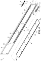
FIG. 3 is a diagram illustrating a slide rail assembly including a first rail, a second rail and a third rail according to an embodiment of the present invention; -
FIG. 4 is an exploded view illustrating the slide rail assembly including the first rail, the second rail, the third rail, a first supporting member and a second supporting member according to the embodiment of the present invention; -
FIG. 5 is a diagram illustrating the first supporting member according to the embodiment of the present invention; -
FIG. 6 is a diagram illustrating a part of the first rail according to the embodiment of the present invention; -
FIG. 7 is a cross-section diagram illustrating the first rail according to the embodiment of the present invention; -
FIG. 8 is a diagram illustrating the second rail of the slide rail assembly able to be detached from the first rail according to the embodiment of the present invention; -
FIG. 9 is a diagram illustrating the second rail of the slide rail assembly able to be moved along a mounting direction to be mounted into the first rail according to the embodiment of the present invention; -
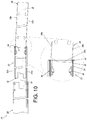
FIG. 10 is a diagram illustrating the second rail of the slide rail assembly being further moved along the mounting direction to be mounted into the first rail according to the embodiment of the present invention; -
FIG. 11 is a diagram illustrating the second rail of the slide rail assembly being yet further moved along the mounting direction to be mounted into the first rail according to the embodiment of the present invention; -
FIG. 12 is a diagram illustrating the second rail of the slide rail assembly having mounted into the first rail according to the embodiment of the present invention; -
FIG. 13 is a diagram illustrating the second rail of the slide rail assembly able to be tilted and being supported by a first supporting portion of the first supporting member of the first rail according to the embodiment of the present invention; -
FIG. 14 is a diagram illustrating the second rail of the slide rail assembly may be located at an installation preparing location and being supported by a first supporting portion of the first supporting member of the first rail according to the embodiment of the present invention; -
FIG. 15 is a diagram illustrating the second rail of the slide rail assembly able to be guided by a guiding portion of the first supporting member of the first rail according to the embodiment of the present invention; -
FIG. 16 is a diagram illustrating the second rail of the slide rail assembly able to be supported by a second supporting portion of the first supporting member of the first rail according to the embodiment of the present invention; -
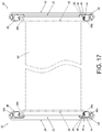
FIG. 17 a diagram illustrating two second rails of two slide rail assemblies respectively arranged on two sides of a carried object, and every second rail able to be supported by every corresponding first supporting portion of the first supporting member of the first rail according to the embodiment of the present invention; and -
FIG. 18 a diagram illustrating the two second rails of the two slide rail assemblies respectively arranged on two sides of the carried object, and every second rail able to be supported by every corresponding second supporting portion of the first supporting member of the first rail according to the embodiment of the present invention. - As shown in
FIG. 3 andFIG. 4 , aslide rail assembly 20 of an embodiment of the present invention includes afirst rail 22, a first supportingmember 24 and asecond rail 26. Preferably, theslide rail assembly 20 further includes athird rail 28. Thefirst rail 22 is movably mounted between thethird rail 28 and thesecond rail 26 to form a three-section slide rail assembly. Thefirst rail 22, thesecond rail 26 and thethird rail 28 are movable relative to each other. In the description below, it will be understood that an X-axis direction is a direction that two slide rails of a slide rail assembly are movable relative to each other when the two slide rails are mounted together (or a length/longitudinal direction of the slide rail). It will also be understood that a Y-axis direction is a transverse direction (or a lateral direction of the slide rail), and a Z-axis direction is a vertical direction (or a height direction of the slide rail which is perpendicular to the length/longitudinal direction and the lateral direction of the slide rail). - The
first rail 22 includes afirst wall 30a, asecond wall 30b and a firstlongitudinal wall 32 connected between thefirst wall 30a and thesecond wall 30b. Apassage 34 is defined by thefirst wall 30a, thesecond wall 30b and the firstlongitudinal wall 32, and configured to accommodate thesecond rail 26. Thefirst rail 22 has afirst end portion 22a, which may also be called a front end portion, and asecond end portion 22b, which may also be called a rear end portion. - The first supporting
member 24 is fixedly arranged on thefirst rail 22 and adjacent to thefirst end portion 22a. Furthermore, the first supportingmember 24 is arranged adjacent to thefirst wall 30a of thefirst rail 22 and located on an entrance of the passage 34 (such as an entry of the passage 34), wherein the entry is arranged at thefirst end portion 22a (the front end portion). The first supportingmember 24 includes a connectingportion 31, amain body portion 33 and an identifyingfeature 35. The connectingportion 31 is configured to be connected to a mountingfeature 37 of the firstlongitudinal wall 32 of thefirst rail 22. Wherein, the connectingportion 31 may be connected to the mountingfeature 37 by engaging or fastening. In another embodiment, the connectingportion 31 may be connected to the mountingfeature 37 by riveting, screwing, or welding, but the present invention is not limited thereto. Themain body portion 33 is connected to the connectingportion 31, and themain body portion 33 substantially has a longitudinal length. The identifying features 35 is arranged on an end portion of themain body portion 33, and the identifying features 35 is located around the entrance of thefirst rail 22. For example, the identifying features 35 is painted with a special color or has a special shape to provide a maintenance staff can visually identify location of the entrance of thefirst rail 22 according to the identifying features 35. - Preferably, the
slide rail assembly 20 further includes a second supportingmember 36 fixedly arranged on thefirst rail 22 and adjacent to thefirst end portion 22a. Preferably, the first supportingmember 24 and the second supportingmember 36 are made of zinc alloy material. Furthermore, the second supportingmember 36 is arranged adjacent to thesecond wall 30b of thefirst rail 22 and located on the entrance of thepassage 34. The second supportingmember 36 and the first supportingmember 24 have substantially a same structural configuration. The second supportingmember 36 and the first supportingmember 24 are arranged on thefirst rail 22 with a same arrangement method. As a result, Components with denoted in the second supportingmember 36 identical to those in the first supportingmember 24 have identical structures and functions, and further description is omitted herein for simplicity. - The
second rail 26 is longitudinally movable relative to thefirst rail 22 through thepassage 34 of thefirst rail 22, and thesecond rail 26 is able to be detached from thepassage 34 of thefirst rail 22. This arrangement is obvious to those skilled in the art. For simplification, no further illustration is provided. Thesecond rail 26 has afirst end portion 26a, which may be also called a front end portion, and asecond end portion 26b, which may be also called a second end portion. - Preferably, the
second rail 26 includes athird wall 38a, afourth wall 38b and a secondlongitudinal wall 40 connected between thethird wall 38a and thefourth wall 38b. A longitudinal length of thethird wall 38a of thesecond rail 26 is substantially greater than a longitudinal length of thefourth wall 38b. For example, thefourth wall 38b of thesecond end portion 26b of thesecond rail 26 and a part of the secondlongitudinal wall 40 are cut to form a inclined side or an oblique angle, such that the longitudinal length of thethird wall 38a of thesecond rail 26 is substantially greater than the longitudinal length of thefourth wall 38b. - Preferably, when the
second rail 26 has mounted into thepassage 34 of thefirst rail 22, thethird wall 38a, thefourth wall 38b and the secondlongitudinal wall 40 of thesecond rail 26 are located respectively adjacent to thefirst wall 30a, thesecond wall 30b and the firstlongitudinal wall 32 of thefirst rail 22. Theslide rail assembly 20 further includes a slideauxiliary device 42 movably mounted in thepassage 34 of thefirst rail 22. The slideauxiliary device 42 includes a plurality of rolling members 43 (e.g. balls or rollers) configured to support thesecond rail 26, in order to improve the smoothness of moving between thesecond rail 26 and thefirst rail 22. - As shown in
FIG. 5 ,6 and7 , each supportingmember 24, 36 (such as themain body portion 33 of the first supporting member 24) includes a first supportingportion 44, a second supportingportion 46 and a guidingportion 48 arranged between the first supportingportion 44 and the second supportingportion 46. The first supportingportion 44 has a first transverse width T1, and the second supportingportion 46 has a second transverse width T2. The first transverse width T1 is greater than the second transverse width T2. In the present embodiment, the first supportingportion 44 and the second supportingportion 46 are two recessed slots, but the present invention is not limited thereto. - Preferably, each supporting
member 24, 36 (such as themain body portion 33 of the first supporting member 24) further includes a third supportingportion 49 adjacent to the second supportingportion 46. - Preferably, the guiding
portion 48 has an inclined surface or an arc surface. - Preferably, a height difference K is formed between the first supporting
portion 44 and the second supporting portion 46 (as shown inFIG. 7 ). - Preferably, when the first supporting
member 24 and the second supportingmember 36 are respectively mounted to thefirst wall 30a and thesecond wall 30b of thefirst rail 22, a first height H1 is defined between the first supportingportion 44 of the first supportingmember 24 and the first supportingportion 44 of the second supportingmember 36. A second height H2 is defined between the second supportingportion 46 of the first supportingmember 24 and the second supportingportion 46 of the second supportingmember 36. Wherein, the first height H1 is greater than the second height H2 (as shown inFIG. 7 ). - As shown in
FIG. 8 , thesecond rail 26 is able to be detached from thepassage 34 of thefirst rail 22. That is to say, thesecond rail 26 and thefirst rail 22 are away from each other. It is noticed that, a third height H3 is defined between thethird wall 38a and thefourth wall 38b of thesecond rail 26, and the first height H1 is greater than the third height H3. In addition, when thesecond rail 26 is detached from thepassage 34 of thefirst rail 22, thesecond rail 26 can be reinserted again according to the identifyingfeature 35 of each supportingmember second end portion 26b of thesecond rail 26 toward the entrance of thefirst rail 22 according to the identifying features 35, such that thesecond rail 26 is able to be easily mounted into thepassage 34 of thefirst rail 22 again. - As shown in
FIG. 8 to FIG. 11 , when thesecond rail 26 is mounted into thepassage 34 of thefirst rail 22 from outside of thepassage 34 of thefirst rail 22, the first supportingportion 44 of the first supportingmember 24 is configured to support the second rail 26 (as shown inFIG. 9 ). When thesecond rail 26 is moved along a mounting direction D1, thesecond rail 26 is guided to the second supportingportion 46 of the first supportingmember 24 through the guidingportion 48 of the first supporting member 24 (as shown inFIG. 10 ), and the second supportingportion 46 of the first supportingmember 24 is configured to support the second rail 26 (as shown inFIG. 11 ) . - Preferably, during the process of mounting, the
second end portion 26b of thesecond rail 26 is able to be easily inserted into thepassage 34 from the entrance of thefirst rail 22 because the first height H1 is greater than the third height H3 (as shown inFIG. 8 ). Furthermore, a longitudinal length of thethird wall 38a of thesecond rail 26 is substantially greater than a longitudinal length of thefourth wall 38b. Therefore, thethird wall 38a of thesecond rail 26 can be supported by the first supportingportion 44 of the first supportingmember 24 as a preliminary (as shown ifFIG. 9 ). When thesecond rail 26 is moved along the mounting direction D1, thesecond rail 26 can be guided by the guidingportion 48 of the first supporting member 24 (as shown inFIG. 10 ) until thesecond rail 26 is located on the second supportingportion 46 of the first supporting member 24 (as shown inFIG. 11 ). In such status, the second supportingportion 46 of the first supportingmember 24 and the second supportingportion 46 of the second supportingmember 36 are able to respectively support thethird wall 38a of thesecond rail 26 and thefourth wall 38b (as shown inFIG. 11 ). - As shown in
FIG. 12 , when thesecond rail 26 is further moved along the mounting direction D1 and mounted into thepassage 34 of thefirst rail 22, the plurality of rollingmembers 43 of the slideauxiliary device 42 are able to be configured to support thesecond rail 26. Preferably, the slideauxiliary device 42 includes a plurality of upper rollingmembers 43 and a plurality oflower rolling members 43 respectively configured to support thethird wall 38a of thesecond rail 26 and thefourth wall 38b. Preferably, theslide rail assembly 20 further includes at least one slide auxiliary structure, such as a first slideauxiliary structure 51 and a second slide auxiliary structure 52. The first slideauxiliary structure 51 and the second slide auxiliary structure 52 both include a plurality of rolling features 54. The plurality of rolling features 54 (e.g. balls or rollers) are configured to support thefirst wall 30a of thefirst rail 22 and thesecond wall 30b, in order to improve the smoothness of moving between thefirst rail 22 and thethird rail 28. - It is noticed that when the
second rail 26 has mounted into thepassage 34 of thefirst rail 22, thesecond rail 26 is able to be longitudinally moved along a detaching direction D2 opposite to the mounting direction D1 to be dismounted from thepassage 34 of the first rail 22 (please refer toFIG. 8 ). - As shown in
FIG. 13 to FIG. 16 , the cross sections of thethird wall 38a and thefourth wall 38b of thesecond rail 26 both include anarc section 56 and anend section 58. Thearc section 56 is transversely (laterally) extended from the secondlongitudinal wall 40. Contour of thearc section 56 can correspond to contour of the plurality of rolling members 43 (e.g. rollers). Theend section 58 is connected to thearc section 56. - Furthermore, due to the first height H1 is greater than the third height H3 (as shown in
FIG. 13 ), when thesecond rail 26 is mounted into thepassage 34 of thefirst rail 22 from outside of thepassage 34 of thefirst rail 22, if a carried object is heavy or mounting space is small, the maintenance staff can insert thesecond rail 26 into thepassage 34 from the entrance of thefirst rail 22 at an inclined angle (as shown inFIG. 13 ). Theend section 58 of thethird wall 38a of thesecond rail 26 can be supported by the first supportingportion 44 of the first supportingmember 24 as a preliminary. Preferably, the first transverse width T1 of the first supportingportion 44 of the first supportingmember 24 is substantially greater than a transverse width of theend section 58 of thethird wall 38a of thesecond rail 26. Therefore, for theend section 58 of thethird wall 38a of thesecond rail 26, a moving space formed by the first transverse width T1 to allow theend section 58 of thethird wall 38a of thesecond rail 26 to easily insert into the space of the first transverse width T1 and be supported by the first supportingportion 44. On the other hand, through the first transverse width T1 of the first supportingportion 44 of the first supportingmember 24 being substantially greater than the transverse width of theend section 58 of thethird wall 38a of thesecond rail 26, a mounting tolerance between the first supportingportion 44 of the first supportingmember 24 and theend section 58 of thethird wall 38a of thesecond rail 26 is allowed. Thereby, thesecond rail 26 can be adjusted to a pre-mounted position (as shown inFIG. 14 and please further refer toFIG. 9 ). When thesecond rail 26 is moved along the mounting direction D1, thesecond rail 26 can be guided by the guidingportion 48 of the first supporting member 24(as shown inFIG. 15 and please further refer toFIG. 10 ) until thesecond rail 26 is guided and moved to the second supportingportion 46 of the first supporting member 24(as shown inFIG. 16 and please further refer toFIG. 11 ). In such status, the second supportingportion 46 of the first supportingmember 24 is able to be configured to support theend section 58 of thethird wall 38a of thesecond rail 26, the second supportingportion 46 of the second supportingmember 36 is able to be configured to support theend section 58 of thefourth wall 38b of the second rail 26 (as shown inFIG. 16 and please further refer toFIG. 11 ) . In addition, the third supportingportion 49 of the first supportingmember 24 has curved or convex contour to support thearc section 56 of thethird wall 38a of thesecond rail 26, and the third supportingportion 49 of the second supportingmember 36 has curved or convex contour to support thearc section 56 of thefourth wall 38b of thesecond rail 26. - In other words, when the
second rail 26 is supported by the first supportingportion 44 of the first supportingmember 24, the maintenance staff may just apply a force along the mounting direction D1 to push thesecond rail 26, such that thesecond rail 26 is able to be moved along the guidingportion 48 of the first supportingmember 24 to the second supportingportion 46 of the second supportingmember 36 and the second supportingportion 46 of the first supportingmember 24 until thesecond rail 26 totally located in thepassage 34 of thefirst rail 22. Thesecond rail 26 is able to be supported by the plurality of rollingmembers 43 of the slideauxiliary device 42. - As shown in
FIG. 17 andFIG. 18 , the twoslide rail assemblies 20 can be arranged on two sides of a rack cabinet (not shown in figure), and eachslide rail assembly 20 includes thefirst rail 22, thesecond rail 26 and thethird rail 28. Wherein, thesecond rails 26 of the twoslide rail assemblies 20 can be arranged on two sides of a carriedobject 60. - When the
second rail 26 is detached from thepassage 34 of thefirst rail 22 and thesecond rail 26 has to be reinserted again into thepassage 34 of thefirst rail 22 from outside of thepassage 34 of thefirst rail 22, similar to above mounting principle, the first supportingportion 44 of the first supportingmember 24 is able to be configured to support thesecond rail 26 as a preliminary (as shown inFIG. 17 and please further refer toFIG. 9 andFIG. 14 ). When thesecond rail 26 is moved along the mounting direction D1, thesecond rail 26 is guided to the second supportingportion 46 of the first supportingmember 24 through the guidingportion 48 of the first supporting member 24(as shown inFIG. 18 and please further refer toFIG. 11 andFIG. 16 ). The second supportingportion 46 of the first supportingmember 24 is configured to support thesecond rail 26. - It is noticed that, as shown in
FIG. 5 andFIG. 7 , the first supportingmember 24 further includes a supportingsection 240 and a connectingguide section 241. A distance is formed between the supportingsection 240 and the first supportingportion 44 of the first supportingmember 24 in the transverse direction (e.g., the Y-axis direction), and the connectingguide section 241 is connected to one side of the supportingsection 240 and to one side of the first supportingportion 44 and is a guide inclined surface. When thesecond rail 26 enters thepassage 34 of thefirst rail 22 from the entrance at the inclined angle and theend section 58 is located on the supportingsection 240, theend section 58 will follow the location adjustment of the anothersecond rail 26 on the another first supportingmember 24 to be synchronously moved to theguiding section 241 in the transverse direction (e.g., the Y-axis direction), and theend section 58 is further guided to the first supportingportion 44. In other words, the guiding inclined surface (e.g., the connecting guide section 241) may be configured to guide theend section 58 of thethird wall 38a of thesecond rail 26 into thefirst support portion 44 of thefirst support 24. - An embodiment of the present invention also provides a rail mounting method of the
slide rail assembly 20. The rail mounting method includes the following steps: - Provide a
first rail 22 having apassage 34, wherein a slideauxiliary device 42 is arranged in thepassage 34, and the slideauxiliary device 42 includes a plurality of rollingmembers 43; - Provide a first supporting
member 24 arranged on thefirst rail 22 and located on an entrance of the passage 34 (such as an entry of the passage 34), wherein the first supportingmember 24 includes a first supportingportion 44, a second supportingportion 46 and the guidingportion 48 arranged between the first supportingportion 44 and the second supportingportion 46, a height difference K is formed between the first supportingportion 44 and the second supportingportion 46; - Provide a
second rail 26, wherein when thesecond rail 26 is mounted into thepassage 34 of thefirst rail 22 from outside of thepassage 34 of thefirst rail 22, the first supportingportion 44 of the first supportingmember 24 is configured to support thesecond rail 26; and - Push the
second rail 26 along a mounting direction D1 to move thesecond rail 26, such that thesecond rail 26 is guided to the second supportingportion 46 through the guidingportion 48, wherein when thesecond rail 26 is further moved along the mounting direction D1, the plurality of rollingmembers 43 of the slideauxiliary device 42 are configured to support thesecond rail 26. Since the technical features of the mounting method are illustrated above and disclosed onFIG. 9 to FIG. 16 , related description is omitted herein for simplicity. - Compared to the prior art, the
slide rail assembly 20 of the present embodiment has advantages over the prior art by the following perspectives: - 1. The first supporting
member 24 is arranged on thefirst rail 22, and the first supportingmember 24 includes the first supportingportion 44, the second supportingportion 46 and the guidingportion 48. When thesecond rail 26 is mounted into thepassage 34 of thefirst rail 22 from outside of thepassage 34 of thefirst rail 22, thesecond rail 26 can be supported by the first supportingportion 44 as a preliminary. When thesecond rail 26 is further moved along the mounting direction D1, thesecond rail 26 is guided to the second supportingportion 46 through the guidingportion 48, and the second supportingportion 46 is configured to support thesecond rail 26. - 2. When the
second rail 26 has mounted into thepassage 34 of thefirst rail 22, the plurality of rollingmembers 43 of the slideauxiliary device 42 is able to be configured to support thesecond rail 26. - 3. The first height H1 is defined between the first supporting
portion 44 of the first supportingmember 24 and the first supportingportion 44 of the second supportingmember 36, and the second height H2 is defined between the second supportingportion 46 of the first supportingmember 24 and the second supportingportion 46 of the second supportingmember 36. The first height H1 is greater than the second height H2. The third height H3 is defined between thethird wall 38a and thefourth wall 38b of thesecond rail 26. Wherein, the first height H1 is greater than the third height H3. - 4. A longitudinal length of the
third wall 38a of thesecond rail 26 is substantially greater than a longitudinal length of thefourth wall 38b.
Claims (11)
- A slide rail assembly (20), comprising:a first rail (22) comprising a first wall (30a), a second wall (30b) and a first longitudinal wall (32) connected between the first wall (30a) and the second wall (30b), a passage (34) being defined by the first wall (30a), the second wall (30b) and the first longitudinal wall (32);characterized by:a first supporting member (24) arranged on the first rail (22), the first supporting member (24) comprising a first supporting portion (44), a second supporting portion (46) and a guiding portion (48) arranged between the first supporting portion (44) and the second supporting portion (46), the first supporting portion (44) having a first transverse width, the second supporting portion (46) having a second transverse width, and the first transverse width being greater than the second transverse width; anda second rail (26);wherein when the second rail (26) is mounted into the passage (34) of the first rail (22) from outside of the passage (34) of the first rail (22), the first supporting portion (44) is configured to support the second rail (26), when the second rail (26) is moved along a mounting direction, the second rail (26) is guided to the second supporting portion (46) through the guiding portion (48) and the second supporting portion (46) is configured to support the second rail (26).
- The slide rail assembly (20) of claim 1, further characterized by a slide auxiliary device (42) arranged in the passage (34) of the first rail (22), the slide auxiliary device (42) comprising a plurality of rolling members (43), wherein when the second rail (26) is further moved along the mounting direction and mounted into the passage (34) of the first rail (22), the plurality of rolling members (43) of the slide auxiliary device (42) are configured to support the second rail (26).
- The slide rail assembly (20) of claim 1 or 2, characterized in that the guiding portion (48) has an inclined surface or an arc surface.
- The slide rail assembly (20) of any of claims 1-3, characterized in that a height difference is formed between the first supporting portion (44) and the second supporting portion (46).
- The slide rail assembly (20) of any of claims 1-4, characterized in that the first supporting member (24) is located on an entrance of the passage (34) adjacent to the first wall (30a) of the first rail (22), the first supporting member (24) further comprises an identifying features (35) located around the entrance.
- The slide rail assembly (20) of claim 5, further characterized by a second supporting member (36) arranged on the first rail (22), the second supporting member (36) being located on the entrance of the passage (34) adjacent to the second wall (30b) of the first rail (22), wherein the second supporting member (36) and the first supporting member (24) have substantially a same structural configuration.
- The slide rail assembly (20) of claim 6, characterized in that a first height is defined between the first supporting portion (44) of the first supporting member (24) and the first supporting portion (44) of the second supporting member (36), a second height is defined between the second supporting portion (46) of the first supporting member (24) and the second supporting portion (46) of the second supporting member (36), the first height is greater than the second height.
- The slide rail assembly (20) of claim 7, characterized in that the second rail (26) comprises a third wall (38a), a fourth wall (38b) and a second longitudinal wall (40) connected between the third wall (38a) and the fourth wall (38b), a third height is defined between the third wall (38a) and the fourth wall (38b), the first height is greater than the third height.
- The slide rail assembly (20) of claim 8, characterized in that a longitudinal length of the third wall (38a) of the second rail (26) is substantially greater than a longitudinal length of the fourth wall (38b).
- The slide rail assembly (20) of claim 8 or 9, characterized in that the third wall (38a) of the second rail (26) comprises an arc section (56) and an end section (58) connected to the arc section (56), the first supporting member (24) further comprises a third supporting portion (49) adjacent to the second supporting portion (46), when the second rail (26) is mounted into the passage (34) of the first rail (22) from outside of the passage (34) of the first rail (22), the first supporting portion (44) of the first supporting member (24) is configured to support the end section (58) of the third wall (38a) of the second rail (26), when the second rail (26) is moved along the mounting direction, the second rail (26) is guided to the second supporting portion (46) through the guiding portion (48) of the first supporting member (24), the second supporting portion (46) of the first supporting member (24) is configured to support the end section (58) of the third wall (38a) of the second rail (26), the third supporting portion (49) of the first supporting member (24) is configured support the arc section (56) of the third wall (38a) of the second rail (26).
- The slide rail assembly (20) of any of claims 1-10, characterized in that when the second rail (26) is mounted into the passage (34) of the first rail (22), the third wall (38a), the fourth wall (38b) and the second longitudinal wall (40) of the second rail (26) are respectively adjacent to the first wall (30a), the second wall (30b) and the first longitudinal wall (32) of the first rail (22).
Applications Claiming Priority (1)
| Application Number | Priority Date | Filing Date | Title |
|---|---|---|---|
| TW109115958A TWI712380B (en) | 2020-05-12 | 2020-05-12 | Slide rail assembly and rails mounting method thereof |
Publications (2)
| Publication Number | Publication Date |
|---|---|
| EP3911135A1 true EP3911135A1 (en) | 2021-11-17 |
| EP3911135B1 EP3911135B1 (en) | 2026-04-29 |
Family
ID=73288426
Family Applications (1)
| Application Number | Title | Priority Date | Filing Date |
|---|---|---|---|
| EP20206644.5A Active EP3911135B1 (en) | 2020-05-12 | 2020-11-10 | Slide rail assembly |
Country Status (4)
| Country | Link |
|---|---|
| US (1) | US11213124B2 (en) |
| EP (1) | EP3911135B1 (en) |
| JP (1) | JP7050885B2 (en) |
| TW (1) | TWI712380B (en) |
Families Citing this family (3)
| Publication number | Priority date | Publication date | Assignee | Title |
|---|---|---|---|---|
| TWI751080B (en) | 2021-05-04 | 2021-12-21 | 川湖科技股份有限公司 | Slide rail assembly and slide rail kit thereof |
| TWI815701B (en) | 2022-10-13 | 2023-09-11 | 川湖科技股份有限公司 | Slide rail assembly |
| TWI892780B (en) * | 2024-08-02 | 2025-08-01 | 富世達股份有限公司 | Slide rail device |
Citations (3)
| Publication number | Priority date | Publication date | Assignee | Title |
|---|---|---|---|---|
| US6220683B1 (en) * | 2000-06-13 | 2001-04-24 | Yin Da Slide Co., Ltd. | Sliding track assembley for drawer |
| US20060244349A1 (en) * | 2005-05-02 | 2006-11-02 | Ken-Ching Chen | Positioning device for drawer slide bearing carrier |
| EP3451808A1 (en) * | 2017-08-28 | 2019-03-06 | King Slide Works Co., Ltd. | Slide rail assembly and mounting method for slide rails |
Family Cites Families (7)
| Publication number | Priority date | Publication date | Assignee | Title |
|---|---|---|---|---|
| US8780565B2 (en) | 2011-02-22 | 2014-07-15 | Dell Products L.P. | Information handling system slide rail alignment support |
| TWI522063B (en) * | 2013-02-08 | 2016-02-21 | 川湖科技股份有限公司 | Support arrangement for use in a bracket and a slide rail |
| US9033434B2 (en) | 2013-09-30 | 2015-05-19 | Sauder Woodworking Co. | Drawer glide |
| TWI565396B (en) | 2015-11-04 | 2017-01-01 | 川湖科技股份有限公司 | Slide rail assembly |
| JP6787805B2 (en) | 2017-02-01 | 2020-11-18 | 永大産業株式会社 | Storage device and installation method of storage device |
| TWI670030B (en) * | 2018-09-10 | 2019-09-01 | 川湖科技股份有限公司 | Slide rail assembly |
| CN110893055B (en) * | 2018-09-12 | 2021-07-13 | 川湖科技股份有限公司 | Sliding rail assembly |
-
2020
- 2020-05-12 TW TW109115958A patent/TWI712380B/en active
- 2020-10-11 US US17/067,752 patent/US11213124B2/en active Active
- 2020-11-10 EP EP20206644.5A patent/EP3911135B1/en active Active
- 2020-12-04 JP JP2020201732A patent/JP7050885B2/en active Active
Patent Citations (3)
| Publication number | Priority date | Publication date | Assignee | Title |
|---|---|---|---|---|
| US6220683B1 (en) * | 2000-06-13 | 2001-04-24 | Yin Da Slide Co., Ltd. | Sliding track assembley for drawer |
| US20060244349A1 (en) * | 2005-05-02 | 2006-11-02 | Ken-Ching Chen | Positioning device for drawer slide bearing carrier |
| EP3451808A1 (en) * | 2017-08-28 | 2019-03-06 | King Slide Works Co., Ltd. | Slide rail assembly and mounting method for slide rails |
Also Published As
| Publication number | Publication date |
|---|---|
| TW202142146A (en) | 2021-11-16 |
| TWI712380B (en) | 2020-12-11 |
| US20210353059A1 (en) | 2021-11-18 |
| JP2021178163A (en) | 2021-11-18 |
| US11213124B2 (en) | 2022-01-04 |
| JP7050885B2 (en) | 2022-04-08 |
| EP3911135B1 (en) | 2026-04-29 |
Similar Documents
| Publication | Publication Date | Title |
|---|---|---|
| US11213124B2 (en) | Slide rail assembly and rails mounting method thereof | |
| US10377394B2 (en) | Unit storage device and railway vehicle | |
| EP3451808B1 (en) | Slide rail assembly and mounting method for slide rails | |
| US20160294166A1 (en) | Module extraction appartatus of high voltage direct current system | |
| US20200113763A1 (en) | Gates with transition ramps for overhead lifting rails | |
| EP3352547A1 (en) | Slide rail assembly | |
| JP2013249056A (en) | Wall installation system and method | |
| US4961648A (en) | Pull-out guide assembly for drawers or the like | |
| EP4087375B1 (en) | Slide rail assembly | |
| CN113677144B (en) | Sliding rail assembly and sliding rail installation method thereof | |
| CN108637023B (en) | Guide beam assembly structure of rolling mill | |
| US10463150B2 (en) | Slide rail assembly | |
| JP7843129B2 (en) | Specimen testing equipment | |
| DE102013111043B4 (en) | Crane track arrangement for a suspension crane | |
| CN106714499A (en) | Sliding rail assembly | |
| CN220765641U (en) | Trolley structure | |
| EP4090142A1 (en) | Slide rail mechanism and slide rail kit thereof | |
| CN222028895U (en) | Guide rail installation type voltage transformer cabinet | |
| CN218586803U (en) | Combined cable bridge capable of being spliced | |
| CN219892706U (en) | Isolated form group grounding isolation box | |
| CN110861995B (en) | Conjoined roller mechanism, moving device and elevator | |
| CN115306823B (en) | Slide rail assembly and slide rail kit | |
| US20250171054A1 (en) | Rail support member, conveyance device, and method of supporting rail in conveyance device | |
| JP2021066277A (en) | Railway vehicle interior part fitting structure | |
| CN215516258U (en) | Elevator guide rail adjusting device |
Legal Events
| Date | Code | Title | Description |
|---|---|---|---|
| PUAI | Public reference made under article 153(3) epc to a published international application that has entered the european phase |
Free format text: ORIGINAL CODE: 0009012 |
|
| STAA | Information on the status of an ep patent application or granted ep patent |
Free format text: STATUS: THE APPLICATION HAS BEEN PUBLISHED |
|
| STAA | Information on the status of an ep patent application or granted ep patent |
Free format text: STATUS: REQUEST FOR EXAMINATION WAS MADE |
|
| AK | Designated contracting states |
Kind code of ref document: A1 Designated state(s): AL AT BE BG CH CY CZ DE DK EE ES FI FR GB GR HR HU IE IS IT LI LT LU LV MC MK MT NL NO PL PT RO RS SE SI SK SM TR |
|
| B565 | Issuance of search results under rule 164(2) epc |
Effective date: 20210413 |
|
| 17P | Request for examination filed |
Effective date: 20211110 |
|
| RBV | Designated contracting states (corrected) |
Designated state(s): AL AT BE BG CH CY CZ DE DK EE ES FI FR GB GR HR HU IE IS IT LI LT LU LV MC MK MT NL NO PL PT RO RS SE SI SK SM TR |
|
| STAA | Information on the status of an ep patent application or granted ep patent |
Free format text: STATUS: EXAMINATION IS IN PROGRESS |
|
| 17Q | First examination report despatched |
Effective date: 20230426 |
|
| GRAP | Despatch of communication of intention to grant a patent |
Free format text: ORIGINAL CODE: EPIDOSNIGR1 |
|
| STAA | Information on the status of an ep patent application or granted ep patent |
Free format text: STATUS: GRANT OF PATENT IS INTENDED |
|
| INTG | Intention to grant announced |
Effective date: 20260109 |
|
| GRAS | Grant fee paid |
Free format text: ORIGINAL CODE: EPIDOSNIGR3 |
|
| GRAA | (expected) grant |
Free format text: ORIGINAL CODE: 0009210 |
|
| STAA | Information on the status of an ep patent application or granted ep patent |
Free format text: STATUS: THE PATENT HAS BEEN GRANTED |
|
| AK | Designated contracting states |
Kind code of ref document: B1 Designated state(s): AL AT BE BG CH CY CZ DE DK EE ES FI FR GB GR HR HU IE IS IT LI LT LU LV MC MK MT NL NO PL PT RO RS SE SI SK SM TR |
|
| REG | Reference to a national code |
Ref country code: CH Ref legal event code: F10 Free format text: ST27 STATUS EVENT CODE: U-0-0-F10-F00 (AS PROVIDED BY THE NATIONAL OFFICE) Effective date: 20260429 Ref country code: GB Ref legal event code: FG4D |
|
| REG | Reference to a national code |
Ref country code: DE Ref legal event code: R096 Ref document number: 602020071079 Country of ref document: DE |