EP3910923A1 - System and method for detecting upward and downward movements of a foot of a user with the aim of triggering a functionality of a device of the user, and user device - Google Patents
System and method for detecting upward and downward movements of a foot of a user with the aim of triggering a functionality of a device of the user, and user device Download PDFInfo
- Publication number
- EP3910923A1 EP3910923A1 EP21173691.3A EP21173691A EP3910923A1 EP 3910923 A1 EP3910923 A1 EP 3910923A1 EP 21173691 A EP21173691 A EP 21173691A EP 3910923 A1 EP3910923 A1 EP 3910923A1
- Authority
- EP
- European Patent Office
- Prior art keywords
- user
- positive
- negative
- signal
- peak
- Prior art date
- Legal status (The legal status is an assumption and is not a legal conclusion. Google has not performed a legal analysis and makes no representation as to the accuracy of the status listed.)
- Granted
Links
Images



Classifications
-
- H—ELECTRICITY
- H04—ELECTRIC COMMUNICATION TECHNIQUE
- H04M—TELEPHONIC COMMUNICATION
- H04M1/00—Substation equipment, e.g. for use by subscribers
- H04M1/72—Mobile telephones; Cordless telephones, i.e. devices for establishing wireless links to base stations without route selection
- H04M1/724—User interfaces specially adapted for cordless or mobile telephones
- H04M1/72403—User interfaces specially adapted for cordless or mobile telephones with means for local support of applications that increase the functionality
-
- G—PHYSICS
- G06—COMPUTING OR CALCULATING; COUNTING
- G06F—ELECTRIC DIGITAL DATA PROCESSING
- G06F3/00—Input arrangements for transferring data to be processed into a form capable of being handled by the computer; Output arrangements for transferring data from processing unit to output unit, e.g. interface arrangements
- G06F3/01—Input arrangements or combined input and output arrangements for interaction between user and computer
- G06F3/017—Gesture based interaction, e.g. based on a set of recognized hand gestures
-
- G—PHYSICS
- G06—COMPUTING OR CALCULATING; COUNTING
- G06F—ELECTRIC DIGITAL DATA PROCESSING
- G06F3/00—Input arrangements for transferring data to be processed into a form capable of being handled by the computer; Output arrangements for transferring data from processing unit to output unit, e.g. interface arrangements
- G06F3/01—Input arrangements or combined input and output arrangements for interaction between user and computer
- G06F3/011—Arrangements for interaction with the human body, e.g. for user immersion in virtual reality
-
- G—PHYSICS
- G01—MEASURING; TESTING
- G01R—MEASURING ELECTRIC VARIABLES; MEASURING MAGNETIC VARIABLES
- G01R29/00—Arrangements for measuring or indicating electric quantities not covered by groups G01R19/00 - G01R27/00
- G01R29/12—Measuring electrostatic fields or voltage-potential
-
- G—PHYSICS
- G01—MEASURING; TESTING
- G01R—MEASURING ELECTRIC VARIABLES; MEASURING MAGNETIC VARIABLES
- G01R29/00—Arrangements for measuring or indicating electric quantities not covered by groups G01R19/00 - G01R27/00
- G01R29/24—Arrangements for measuring quantities of charge
-
- H—ELECTRICITY
- H03—ELECTRONIC CIRCUITRY
- H03K—PULSE TECHNIQUE
- H03K17/00—Electronic switching or gating, i.e. not by contact-making and –breaking
- H03K17/94—Electronic switching or gating, i.e. not by contact-making and –breaking characterised by the way in which the control signals are generated
- H03K17/945—Proximity switches
- H03K17/955—Proximity switches using a capacitive detector
-
- H—ELECTRICITY
- H04—ELECTRIC COMMUNICATION TECHNIQUE
- H04N—PICTORIAL COMMUNICATION, e.g. TELEVISION
- H04N23/00—Cameras or camera modules comprising electronic image sensors; Control thereof
- H04N23/60—Control of cameras or camera modules
-
- G—PHYSICS
- G06—COMPUTING OR CALCULATING; COUNTING
- G06F—ELECTRIC DIGITAL DATA PROCESSING
- G06F2218/00—Aspects of pattern recognition specially adapted for signal processing
- G06F2218/12—Classification; Matching
-
- G—PHYSICS
- G06—COMPUTING OR CALCULATING; COUNTING
- G06N—COMPUTING ARRANGEMENTS BASED ON SPECIFIC COMPUTATIONAL MODELS
- G06N20/00—Machine learning
-
- G—PHYSICS
- G06—COMPUTING OR CALCULATING; COUNTING
- G06N—COMPUTING ARRANGEMENTS BASED ON SPECIFIC COMPUTATIONAL MODELS
- G06N5/00—Computing arrangements using knowledge-based models
- G06N5/04—Inference or reasoning models
-
- H—ELECTRICITY
- H04—ELECTRIC COMMUNICATION TECHNIQUE
- H04M—TELEPHONIC COMMUNICATION
- H04M2250/00—Details of telephonic subscriber devices
- H04M2250/12—Details of telephonic subscriber devices including a sensor for measuring a physical value, e.g. temperature or motion
Definitions
- the present invention relates to a system and a method for controlling at least one functionality of an electronic device based on a gesture of a user of the electronic device.
- the present invention also relates to the electronic device which comprises the system.
- the gesture includes moving at least one foot upward and, subsequently, downward by the user, detecting as a consequence of this gesture a variation of the electrostatic charge of the user's body.
- Devices used for the continuous monitoring of a user's body in the environment and during free living conditions are known.
- Various sensors for example for detecting the acceleration, the electrical resistance of the skin, the temperature of the skin, the radiated heat flow and the heart rate, are used in various combinations to determine or derive parameters such as calorie burn rate, type and level of activity and sleep status.
- These devices employ sophisticated algorithms to integrate various acquired data flows, in order to determine output parameters with the best possible precision (e.g., calories burned, type of physical activity, etc.).
- Additional sensors, to detect additional parameters provide algorithms with additional data, to improve their accuracy.
- the use of triaxial accelerometers (often integrated in portable devices) is known for providing an acceleration signal along three orthogonal axes, and processing the acceleration signal by means of step recognition algorithms in order to identify specific signal patterns that may be related to the execution of a step by the user.
- the acceleration signal processing is calibrated on an "average” or “standard” user and does not take into account specific physical conditions or needs (even if only temporary) that may arise. For example, due to physical problems, the user might take very short steps, or with a different pace from that of the average user taken as a reference in the calibration of the recognition algorithm. Or, the movement of the arms, used by software installed on board wearable devices (e.g. smartwatches), may not be indicative of a step in the event that the user has problems in the movement of the same. Other unpredictable conditions may also prevent a correct step counting.
- Electric field sensors are used in alternative or in addition to accelerometer sensors for determining a user's activity, or for helping interpret the signals generated by other sensor devices.
- An electric charge is a fundamental component of nature.
- the electrons of an element are easily transferred to another element in conditions of direct contact between the elements or at a distance.
- a static charge is generated whereby the object with an excess of electrons is negatively charged and the object with a deficiency of electrons is positively charged.
- Electrons move within an object in different ways depending on whether the object is a conducting or insulating object.
- a conductor electrons are more or less evenly distributed throughout the material and may easily move based on the influence of external electric fields.
- the charge mainly exists on the surface. The charge may however be movable, depending on the properties of the material and other environmental factors.
- Devices detecting the variation of the electric field generated by a man during the movements of the same, or exploiting a capacitive-type detection are known. Technologies using the latter type of detection include, for example, touch screens, systems for detecting the occupant position in automobiles, and devices for determining the position, the orientation and the mass of an object, such as, for example, described in patent document US5,844,415 regarding an electric field detection device for determining the position, the mass distribution and the orientation of an object within a defined space, arranging a plurality of electrodes within the defined space.
- This technical solution could also be used to recognize a user's gestures, hand position and orientation, for example for interactive use with a processing system, in place of a mouse or a joystick.
- Patent document US2014/232516 proposes the use of an electrostatic charge sensor to derive a physiological parameter or a user's activity, such as walking, cycling or energy consumption from a field or a capacitive sensor.
- a repetitive action in a time series is detected in order to monitor the type of physical activity performed.
- a system and a method for controlling at least one functionality of an electronic device based on a gesture of a user of the electronic device, and an electronic device that includes the system are provided, as defined in the attached claims.
- FIG. 1 illustrates, schematically, a movement detection system 1 according to an aspect of the present invention.
- the movement detection system 1 comprises a processing unit 2 of an electronic device, or system, 4 and an electrostatic charge variation sensor 6 coupled to the processing unit 2.
- the electrostatic charge variation sensor 6 is integrated in the device 4.
- the processing unit 2 receives a charge variation signal S Q from the electrostatic charge variation sensor 6 and generates, according to the charge variation signal S Q , a command or control signal S C .
- the processing unit 2 implements, in use, a method for recognizing a gesture by a user of the device 4.
- the recognition of this gesture causes the generation of the command or control signal S C , which is for controlling or commanding at least one functionality of the device 4 (for example, enabling or disabling a functionality).
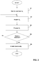
- This method is represented by means of a block diagram in Figure 2 .
- block B1 the functionality to be controlled is considered off or disabled, waiting for the command signal Sc.
- block B3 a step of processing the charge variation signal S Q for extracting significant parameters and parameters identifying the gestures to be detected is carried out.
- block B4 the aforementioned functionality of the device 4 is enabled (block B5); otherwise the method returns to block B2 by continuing the acquisition of the charge variation signal S Q .
- the gestures to be detected are the upward movement from the ground and the successive downward movement to the ground of at least one foot, or leg, of the user. It is evident that the present invention applies analogously to other types of user gestures, such as raising or lowering the whole leg, or an arm, or other gestures. It should also be noted that, in the context of the present invention, the gesture to be detected is intended as a specific gesture performed for the purpose of activating said functionality and is not a more complex physical activity prolonged in time and constituted by the temporal repetition of a plurality of gestures more or less equal or corresponding to each other (as can be, for example, the alternation of movements of the feet during a run or a walk).
- the present invention provides for the extraction of significant parameters, which are typical of the gesture to be detected.
- a possible implementation is described with explicit reference to the raising and lowering movement of the foot. However, what is described can be applied to other gestures.
- Each upward and downward movement generates a variation of electrostatic charge through the user's body, due to an exchange of charges with the ground/floor, which is detected by the electrostatic charge variation sensor 6.
- the sequence, within a predefined time, of upward and downward movements of the user's foot or leg identifies the intention of the user of enabling the aforementioned functionality of the device 4 and involves, therefore, the generation of the command signal S C which enables such functionality.
- These steps are an implementation of block B4, which therefore includes a sub-step of recognizing the upward movement of the foot or leg and, only in the positive case, the passage to a sub-step of recognizing the downward movement of the foot or leg within a first time interval. If the downward movement of the leg occurs within this time interval, then the method moves on to block B5; conversely it returns to block B2.
- the device 4 is a portable electronic device, such as a smartphone, and the functionality to be controlled is the taking of a photo (for example, in selfie mode) by means of a photo- or video-camera of the device 4.
- the processing unit 2 is, in one embodiment, a microcontroller integrated in the device 4.
- the movement detection system 1 has at least one sensitive element, or electrode (identified with the reference number 5 only in Figure 3 ), with which a part of the user's body (e.g., hand or finger) may be placed in direct electrical contact.
- the electrode 5 may be integrated in the case of the device 4, or connected to the device 4 in another way, for example by means of an external cable or wireless connection (for example, integrated in a smartwatch connected to the device 4).
- Other embodiments are possible, as apparent to the skilled in the art, so that the electrode 5 is in electrical contact with a region of the user's body during the step of controlling and commanding the aforementioned functionality.
- the sensitive element (electrode) 5 that collects the external charge may be a metal surface or an electrode coated with dielectric material or again a metal surface placed under the case of the device integrating it. In any case, in use, the user is required to place a finger (or hand, or other portion of the body) in contact with this sensitive element 5.
- the movement detection system 1 is affected by the variation of electrostatic charge due to movements of the user.
- the signal deriving from specific movements may be isolated and identified with respect to other movements that are not of interest and with respect to the background noise present in case of user inactivity.
- the functionality is enabled starting from a condition of substantial stationarity of the user and therefore it is not necessary to carry out a recognition of shapes of the signal S Q to identify the shape deriving from the upward/downward movement of the foot or leg with respect, for example, to that deriving from a complex movement of the arms.
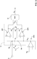
- FIG 3 illustrates an exemplary and non-limiting embodiment of an electrostatic charge variation sensor 6.
- the electrostatic charge variation sensor 6 comprises an input 8a, electrically coupled to the electrode 5 which, in turn, is contactable by a portion of a user's body; the electrostatic charge variation sensor 6 also comprises an input 8b, electrically coupled to the input 8a by means of a resistor R0 and a capacitor C0 in parallel with each other.
- the pair R0, C0 connected to the electrode 5 and placed between the two non-inverting inputs of the two operational amplifiers OP1 and OP2, has the function of accumulating the charges collected by the electrode 5 and of managing the band of the input signal (to filter signals and noises at unwanted frequency).
- the values of the capacitance of C0 and the resistance of R0 may be chosen according to the type of filter that it is desired to form, for example a low-pass filter, with a cut-off frequency of a few tens of Hz, for example 20 Hz.
- the capacitance of C0 is chosen in the range 5pF-5nF.
- the resistance of R0 is chosen in the range 500MOhm-50GOhm.
- the values of the capacitance of C0 and the resistance of R0 may also be chosen according to the impedance of the stage to which they are connected, the usable frequency of the signal Vd and that of the interferences to be filtered (e.g. frequency of the power grid, high frequency electrical noises of the power supply circuits, etc.).
- the voltage (or electric potential) Vd that is established, in use, between the inputs 8a and 8b represents the differential input of an instrumentation amplifier 12.
- the instrumentation amplifier 12 includes two operational amplifiers OP1 and OP2.
- a biasing stage (buffer) OP3 is used for biasing the instrumentation amplifier 12 to a common mode voltage V CM .
- the inverting terminals of the operational amplifiers OP1 and OP2 are connected to each other by means of a resistor R 2 .
- the differential output Vd' is input to an analog-to-digital converter 14, which outputs the charge variation signal S Q for the processing unit 2.
- the charge variation signal S Q is, for example, a high-resolution digital stream (16 bits or 24 bits).
- the analog-to-digital converter 14 is optional, since the processing unit 2 may be configured to work directly on the analog signal, or may itself comprise an analog-to-digital converter for converting the signal Vd'.
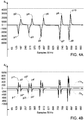
- FIG. 4A illustrates an example of the charge variation signal S Q .
- the values of the potential difference Vd, induced by the charge variation, between the inputs 8a, 8b are represented on the ordinate axis of the charge variation signal S Q .
- This value is expressed here in LSB ("Least Significant Bit"), i.e. the minimum digital value output from the analog-to-digital converter, which is proportional to the potential difference Vd present at the inputs 8a, 8b.
- LSB Location Significant Bit
- 1 LSB corresponds to a value ranging between a few ⁇ V and a few tens of ⁇ V.
- the constant of proportionality depends on the gain of the amplifier, the resolution of the analog-to-digital converter and any digital processing (e.g., oversampling, decimation etc.).
- the representation in LSB is common in the art and disregards a quantification in physical units, since the aim is typically to detect relative variations, with respect to a steady state or base state.
- the progressive numbers of the acquired sample are represented on the abscissa axis of the charge variation signal S Q .
- the reported measurements have been made with a sampling frequency equal to 50Hz, thus each sample is temporally spaced from the following and the previous by 20ms.
- the charge variation signal S Q has a plurality of peaks p1-p10 that follow each other temporally with amplitude much greater than the background noise.
- Each peak p1-p10 is caused by a respective upward movement of the user's foot or downward movement of the user's foot.
- the peaks p1-p10 are identified in the signal Vd' (then sampled generating the signal S Q ), but what described here applies in an equivalent manner to the signal Vd. In fact the amplification stage (instrumentation amplifier of Figure 2 ) is useful, but unnecessary.
- the charge variation signal to be acquired (caused by the movement of the user) is sufficiently large or if the electrical characteristics of the analog-to-digital converter allow it (e.g., high input impedance, high resolution, full scale suitable for the signal to be converted, etc.), then this amplification stage may be omitted, and the inputs 8a and 8b are the inputs of the analog-to-digital converter.
- Negative peaks p1, p3, p5, p7, p9 are generated when the user performs an upward movement of his/her foot
- positive peaks p2, p4, p6, p8, p10 are generated when the user performs a downward movement of his/her foot previously moved upward.
- the negative peak p1 of the signal S Q is generated and, when the same foot is subsequently moved downward, the positive peak p2 in the signal S Q is generated.
- the same situation occurs for the generation of the other pairs of negative and positive peaks (foot that is moved upward: generation of p3, foot that is moved downward: generation of p4, etc.).
- a sampling of the voltage Vd' is provided at a sampling rate of 50 Hz, generating the signal S Q .
- the sampling rate is for example equal to 50 Hz, but may be different, for example chosen in the range 25 Hz ⁇ - 1 kHz.
- a filtering of the signal S Q is also provided, to remove or attenuate any spectral components not related to the movement to be detected.
- a filtering of the signal S Q is also provided, to remove or attenuate any spectral components not related to the movement to be detected.
- parameters of interest are also extracted from the signal S Q (hereinafter, reference is made to "signal S Q " to indifferently identify such signal S Q with or without filtering) which are used to detect the gestures of the user (as said, movement of the foot upward from/downward to the ground) and to discriminate this specific gesture with respect to complex movements such as a prolonged physical activity, walking or running (the latter, in fact, generate a charge variation signal with signal characteristics different from those of the charge variation signal generated by the gesture considered here and useful to activate the functionality of the device 4).
- This operation provides for calculating the derivative with respect to the time of the signal S Q (hereinafter, identified as S Q '); the signal S Q ' is illustrated in Figure 4B .
- the calculation of the temporal derivative therefore has the specific function of extracting, isolating and enabling the identification of said specific characteristics of the gesture to be detected.
- the components of the derivative S Q ' of the charge variation signal S Q which identify the execution, by the user, of the gesture to be detected, are then extracted.
- a comparison by means of double threshold ⁇ Th Q is used to identify the components of the signal S Q ' identifying the expected gesture.
- the variation of the signal S Q of Figure 4A due to the upward movement of the foot generates the negative peak p1, whose derivative over time is represented in Figure 4B by a sequence of two peaks, of which a first negative peak p1' and then a positive peak p1"; similarly, the variation of the signal S Q of Figure 4A due to the successive downward movement of the foot generates the positive peak p2 whose derivative over time is represented, in Figure 4B , by a sequence of two peaks, of which a first positive peak p2' and then a negative peak p2".
- the exceeding (towards negative values) of the threshold -Th Q by the signal S Q ' (peak p1') followed by the successive exceeding (towards positive values) of the threshold +Th Q by the same signal S Q ' (peak p1") is associated with the execution of an upward movement of the foot by the user.
- the exceeding (towards positive values) of the threshold +Th Q by the signal S Q ' (peak p2') followed by the exceeding (towards negative values) of the threshold -Th Q by the same signal S Q ' (peak p2") is associated with the execution of a downward movement of the foot by the user.
- the signal S Q varies slightly, and is substantially constant (unless of a variation due to electrostatic noise phenomena).
- the derivative S Q ' of the signal S Q is, in this context, substantially equal to zero (or with a mean value equal to zero) .
- the derivative S Q ' shows an apparent variation, with positive peaks p1", p2', and negative peaks p1', p2" with respect to the zero value.
- the Applicant has also verified that other movements, such as the oscillation of the user's arm that supports the device 4 during the enabling of the functionality according to the present invention, do not generate an electrostatic charge variation having a trend, in the signals S Q and S Q ', comparable to that of the upward/downward movement of the foot.
- the electrostatic charge variation due to the movement of the arm is much lower than, and different from that, caused by the upward movement of a foot; in fact it does not arise from an exchange of charges with the ground/floor, but from a variation of the electrostatic field, induced by the movement of the body (this effect prevails with respect to the generation or transfer of charges as a result of arm-air friction).
- the thresholds ⁇ Th Q are, in one embodiment, of a fixed and preset type.
- the Applicant has verified that the signal produced by the movement of the leg is so strong with respect to the background noise of the signal S Q ' (and, correspondingly, S Q ) that each threshold ⁇ Th Q may be preset to a value (in modulus) equal to 20-50 times as much as the maximum value reached by the background noise of the signal S Q ', without the risk of acquiring false positives.
- the thresholds ⁇ Th Q may be defined as fixed levels, based on the full scale of the sensor (1/4, 1/2, 3/4, etc.), or may be programmed by the user (e.g. by creating a calibration routine of the "move foot upward” and “move foot downward” gestures, with a user interface asking the user to perform a certain number of repeated actions to estimate the levels of optimal threshold, as well as, possibly, of maximum time between the two events).
- the thresholds ⁇ Th Q may be defined for example by calculating a mean and a standard deviation of the maxima (in the case of positive peaks) and the minima (in the case of negative peaks) and choosing the threshold as the mean decreased or increased (respectively for maxima or minima) by 3 times as much as the standard deviation.
- the threshold ⁇ Th Q is of adaptive type, that is, it varies according to the trend of the signal S Q '.
- the calculation of the threshold ⁇ Th Q of the adaptive type may be performed exploiting techniques known in the state of the art. For example, sliding windows or overlapping windows may be used. Other techniques for real-time calculation of adaptive threshold may be used.
- time t OFF is, for example, the residence time of the signal S Q ' below the threshold +Th Q .
- this time interval ⁇ T OFF should take into account the speed of upward/downward movement of the foot, as the rising and falling edges of the peaks p1-p10 of the signal S Q (and, consequently, of the derivative thereof) vary according to the speed of the upward/downward movement of the foot.
- Figure 5 illustrates, by means of a flow chart, a method for calculating and evaluating the time t OFF elapsing between the upward movement of the foot and the following downward movement of the foot. These steps are part of step B4 of Figure 2 .
- step B4b is carried out wherein a timer T Q which counts the time elapsed from the upward movement of the foot to the following resting of the foot on the ground is started.
- step B4c if the foot has been moved downward, the acquisition of the signal S Q of step B2 stops and step B5 of Figure 2 (enable functionality) is carried out.
- step B4d If the resting of the foot on the ground is not detected at step B4c, it is verified, at step B4d, whether the timer T Q has exceeded the predefined reference interval ⁇ T OFF (for example 1 second, which may be set or modified by the user).
- ⁇ T OFF for example 1 second, which may be set or modified by the user.
- step B4e If not (T Q ⁇ T OFF ), the timer T Q is increased (step B4e), and the method returns to step B4a, to detect the upward movement of the foot based on new samples of the signal S Q acquired.
- t off is the time elapsing between the instant of detection of the foot moved upward and the instant of detection of the foot moved downward.
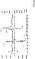
- Figure 6A exemplary illustrates the trend of the signals S Q and S Q ' in the case of rapid movement
- Figure 6B exemplary illustrates the trend of the signals S Q and S Q ' in the case of slow movement.
- the time t OFF is substantially less than the corresponding time t OFF of the situation of Figure 6B .
- the applicant has however verified that the choice of a reference interval ⁇ T OFF of a value equal to 1-2 seconds, with a threshold +Th Q equal to or greater than 100, covers most of the situations that occur in practice, managing to identify both slow and fast commands.
- the step of detecting peaks p1-p10 by means of a threshold may be replaced by a step of recognizing the shape of the signal S Q or the signal S Q ' .
- machine learning and/or artificial intelligence techniques may be used for the automatic recognition of specific patterns of the signal S Q or S Q ' associated with the gesture to be detected (upward/downward movement of the leg), so as to distinguish between different types of gestures, including a step up, a step down, a foot tap on the ground, etc.
- a charge variation sensor of a type not wearable by the user, but configured to remotely detect electrostatic variations generated following the execution of a step by the user may be used.
- a system of this type is a distributed system and may be used, for example, in gaming or augmented reality applications, wherein the user performs his/her movements in a delimited environment, for example a room.
- the present invention applies in a similar manner as described to different types of movements or gestures of the user, in particular other than raising and lowering the foot.
- the present invention applies to a broader raising and lowering movement of the whole leg or a portion thereof, or a raising and lowering movement of the arm, or other movements.
- the present invention offers an opportunity of controlling a device without using the hands, which might be engaged in other purposes (for example to support the device itself). Furthermore, the present invention is not affected by the ambient brightness (critical parameter in application of facial recognition or gesture recognition according to the prior art) and is not affected by the acoustic noise (interfering in the case of voice commands). Even in the case of hands-free, the control through movement of the foot allows for not exerting pressure or movements (some unwanted) directly on the device to be controlled (key pressing, screen touching etc.) with the advantage of not altering the position, the target or the focus (in the case of a photo-camera) thereof.
- the event of a single gesture (e.g., to raise and lower the foot) is analysed to highlight two different sub-movements or sub-gestures, in order to be sure that it is a gesture performed with the intention of enabling or controlling a function of an associated device (and not, for example, a set of steps performed during a run or a walk).
Landscapes
- Engineering & Computer Science (AREA)
- General Engineering & Computer Science (AREA)
- Theoretical Computer Science (AREA)
- Physics & Mathematics (AREA)
- General Physics & Mathematics (AREA)
- Human Computer Interaction (AREA)
- Signal Processing (AREA)
- Multimedia (AREA)
- Computer Networks & Wireless Communication (AREA)
- User Interface Of Digital Computer (AREA)
- Accommodation For Nursing Or Treatment Tables (AREA)
- Chairs Characterized By Structure (AREA)
- Automatic Cycles, And Cycles In General (AREA)
Abstract
Description
- The present invention relates to a system and a method for controlling at least one functionality of an electronic device based on a gesture of a user of the electronic device. The present invention also relates to the electronic device which comprises the system. In particular, the gesture includes moving at least one foot upward and, subsequently, downward by the user, detecting as a consequence of this gesture a variation of the electrostatic charge of the user's body.
- Devices used for the continuous monitoring of a user's body in the environment and during free living conditions are known. Various sensors, for example for detecting the acceleration, the electrical resistance of the skin, the temperature of the skin, the radiated heat flow and the heart rate, are used in various combinations to determine or derive parameters such as calorie burn rate, type and level of activity and sleep status. These devices employ sophisticated algorithms to integrate various acquired data flows, in order to determine output parameters with the best possible precision (e.g., calories burned, type of physical activity, etc.). Additional sensors, to detect additional parameters, provide algorithms with additional data, to improve their accuracy.
- In particular, as regards the step counting, the use of triaxial accelerometers (often integrated in portable devices) is known for providing an acceleration signal along three orthogonal axes, and processing the acceleration signal by means of step recognition algorithms in order to identify specific signal patterns that may be related to the execution of a step by the user. However, the acceleration signal processing is calibrated on an "average" or "standard" user and does not take into account specific physical conditions or needs (even if only temporary) that may arise. For example, due to physical problems, the user might take very short steps, or with a different pace from that of the average user taken as a reference in the calibration of the recognition algorithm. Or, the movement of the arms, used by software installed on board wearable devices (e.g. smartwatches), may not be indicative of a step in the event that the user has problems in the movement of the same. Other unpredictable conditions may also prevent a correct step counting.
- Electric field sensors are used in alternative or in addition to accelerometer sensors for determining a user's activity, or for helping interpret the signals generated by other sensor devices.
- An electric charge is a fundamental component of nature. The electrons of an element are easily transferred to another element in conditions of direct contact between the elements or at a distance. When the charge is transferred between two electrically insulated objects, a static charge is generated whereby the object with an excess of electrons is negatively charged and the object with a deficiency of electrons is positively charged.
- Electrons move within an object in different ways depending on whether the object is a conducting or insulating object. In a conductor, electrons are more or less evenly distributed throughout the material and may easily move based on the influence of external electric fields. In an insulator, the charge mainly exists on the surface. The charge may however be movable, depending on the properties of the material and other environmental factors.
- Devices detecting the variation of the electric field generated by a man during the movements of the same, or exploiting a capacitive-type detection are known. Technologies using the latter type of detection include, for example, touch screens, systems for detecting the occupant position in automobiles, and devices for determining the position, the orientation and the mass of an object, such as, for example, described in patent document
US5,844,415 regarding an electric field detection device for determining the position, the mass distribution and the orientation of an object within a defined space, arranging a plurality of electrodes within the defined space. This technical solution could also be used to recognize a user's gestures, hand position and orientation, for example for interactive use with a processing system, in place of a mouse or a joystick. - Patent document
US2014/232516 proposes the use of an electrostatic charge sensor to derive a physiological parameter or a user's activity, such as walking, cycling or energy consumption from a field or a capacitive sensor. In this document, a repetitive action in a time series (walking, running, etc.) is detected in order to monitor the type of physical activity performed. - The scientific document by K. Kurita, "Development of Non-Contact Measurement System of Human Stepping", SICE Annual Conference 2008, Japan, illustrates a system and a method for counting the steps taken by a subject exploiting a contactless technique. This technique provides for detecting the electrostatic induction current, generated as a direct consequence of the movement of the subject in the environment, through an electrode placed at a distance of 1.5 m from the subject. However, the experiment illustrated in this document is carried out under ideal conditions, and is a mere demonstration of the technology feasibility to step counting. This document does not teach a technique applicable in real life conditions, wherein the subject executes, in addition to steps, a plurality of other activities, each of which causes a variation of the electrostatic charge detected by the sensor. In these conditions, the detection of signal components due exclusively to the subject's steps is complex and does not guarantee high reliability on the accuracy of the detection and consequent counting.
- The need is therefore felt to make up for the shortcomings of the prior art by providing a system and a method for controlling at least one functionality of an electronic device based on a gesture of a user of the electronic device that is economical but reliable, and that requires a reduced computational load.
- According to the present invention, a system and a method for controlling at least one functionality of an electronic device based on a gesture of a user of the electronic device, and an electronic device that includes the system are provided, as defined in the attached claims.
- For a better understanding of the invention, embodiments thereof are now described, purely by way of non-limiting example and with reference to the attached drawings, wherein:
-
Figure 1 schematically illustrates a system for controlling at least one functionality of an electronic device including an electrostatic electric charge variation sensor, according to an embodiment of the present invention; -
Figure 2 illustrates, by means of a block diagram, a method for controlling at least one functionality of an electronic device, according to the present invention; -
Figure 3 illustrates an embodiment of the electric charge variation sensor ofFigure 1 ; -
Figure 4A illustrates an electric charge variation signal generated at the output of the sensor ofFigure 3 following a sequence of gestures of upward and downward movements of a foot by the user of the electronic device ofFigure 1 ; -
Figure 4B illustrates the derivative function of the electric charge variation signal ofFigure 4A ; -
Figure 5 illustrates, by means of a flow chart, substeps of the method ofFigure 2 ; -
Figure 6A exemplary illustrates the trend of the electric charge variation signal and the derivative thereof in the case of a rapid upward and downward movement of a foot by the user; and -
Figure 6B exemplary illustrates the trend of the electric charge variation signal and the derivative thereof in the case of a slow upward and downward movement of a foot by the user. -
Figure 1 illustrates, schematically, amovement detection system 1 according to an aspect of the present invention. Themovement detection system 1 comprises aprocessing unit 2 of an electronic device, or system, 4 and an electrostaticcharge variation sensor 6 coupled to theprocessing unit 2. In one embodiment, the electrostaticcharge variation sensor 6 is integrated in thedevice 4. Theprocessing unit 2 receives a charge variation signal SQ from the electrostaticcharge variation sensor 6 and generates, according to the charge variation signal SQ, a command or control signal SC. - The
processing unit 2 implements, in use, a method for recognizing a gesture by a user of thedevice 4. The recognition of this gesture causes the generation of the command or control signal SC, which is for controlling or commanding at least one functionality of the device 4 (for example, enabling or disabling a functionality). - This method is represented by means of a block diagram in
Figure 2 . - With reference to
Figure 2 , block B1, the functionality to be controlled is considered off or disabled, waiting for the command signal Sc. - Then, block B2, a charge variation signal SQ generated by the electrostatic
charge variation sensor 6 is acquired. - Then, block B3, a step of processing the charge variation signal SQ for extracting significant parameters and parameters identifying the gestures to be detected is carried out.
- In the event that such gestures are detected, block B4, the aforementioned functionality of the
device 4 is enabled (block B5); otherwise the method returns to block B2 by continuing the acquisition of the charge variation signal SQ. - In one embodiment of the present invention, not limitative of the same, the gestures to be detected are the upward movement from the ground and the successive downward movement to the ground of at least one foot, or leg, of the user. It is evident that the present invention applies analogously to other types of user gestures, such as raising or lowering the whole leg, or an arm, or other gestures. It should also be noted that, in the context of the present invention, the gesture to be detected is intended as a specific gesture performed for the purpose of activating said functionality and is not a more complex physical activity prolonged in time and constituted by the temporal repetition of a plurality of gestures more or less equal or corresponding to each other (as can be, for example, the alternation of movements of the feet during a run or a walk). To this end, in order to discriminate between a voluntary gesture performed for the purpose of activating the functionality of the
device 4 and a gesture which is part of a complex activity such as running, the present invention provides for the extraction of significant parameters, which are typical of the gesture to be detected. In the following, a possible implementation is described with explicit reference to the raising and lowering movement of the foot. However, what is described can be applied to other gestures. - Each upward and downward movement generates a variation of electrostatic charge through the user's body, due to an exchange of charges with the ground/floor, which is detected by the electrostatic
charge variation sensor 6. The sequence, within a predefined time, of upward and downward movements of the user's foot or leg identifies the intention of the user of enabling the aforementioned functionality of thedevice 4 and involves, therefore, the generation of the command signal SC which enables such functionality. These steps are an implementation of block B4, which therefore includes a sub-step of recognizing the upward movement of the foot or leg and, only in the positive case, the passage to a sub-step of recognizing the downward movement of the foot or leg within a first time interval. If the downward movement of the leg occurs within this time interval, then the method moves on to block B5; conversely it returns to block B2. - By way of non-limiting example, the
device 4 is a portable electronic device, such as a smartphone, and the functionality to be controlled is the taking of a photo (for example, in selfie mode) by means of a photo- or video-camera of thedevice 4. - The
processing unit 2 is, in one embodiment, a microcontroller integrated in thedevice 4. - The
movement detection system 1 has at least one sensitive element, or electrode (identified with thereference number 5 only inFigure 3 ), with which a part of the user's body (e.g., hand or finger) may be placed in direct electrical contact. Theelectrode 5 may be integrated in the case of thedevice 4, or connected to thedevice 4 in another way, for example by means of an external cable or wireless connection (for example, integrated in a smartwatch connected to the device 4). Other embodiments are possible, as apparent to the skilled in the art, so that theelectrode 5 is in electrical contact with a region of the user's body during the step of controlling and commanding the aforementioned functionality. - The sensitive element (electrode) 5 that collects the external charge may be a metal surface or an electrode coated with dielectric material or again a metal surface placed under the case of the device integrating it. In any case, in use, the user is required to place a finger (or hand, or other portion of the body) in contact with this
sensitive element 5. - The
movement detection system 1 is affected by the variation of electrostatic charge due to movements of the user. The signal deriving from specific movements (in particular, due to the upward and downward movements of a foot or leg) may be isolated and identified with respect to other movements that are not of interest and with respect to the background noise present in case of user inactivity. According to the present invention, however, it is assumed that the functionality is enabled starting from a condition of substantial stationarity of the user and therefore it is not necessary to carry out a recognition of shapes of the signal SQ to identify the shape deriving from the upward/downward movement of the foot or leg with respect, for example, to that deriving from a complex movement of the arms. -
Figure 3 illustrates an exemplary and non-limiting embodiment of an electrostaticcharge variation sensor 6. The electrostaticcharge variation sensor 6 comprises aninput 8a, electrically coupled to theelectrode 5 which, in turn, is contactable by a portion of a user's body; the electrostaticcharge variation sensor 6 also comprises aninput 8b, electrically coupled to theinput 8a by means of a resistor R0 and a capacitor C0 in parallel with each other. The pair R0, C0, connected to theelectrode 5 and placed between the two non-inverting inputs of the two operational amplifiers OP1 and OP2, has the function of accumulating the charges collected by theelectrode 5 and of managing the band of the input signal (to filter signals and noises at unwanted frequency). - The values of the capacitance of C0 and the resistance of R0 may be chosen according to the type of filter that it is desired to form, for example a low-pass filter, with a cut-off frequency of a few tens of Hz, for example 20 Hz. For example, the capacitance of C0 is chosen in the range 5pF-5nF. For example, the resistance of R0 is chosen in the range 500MOhm-50GOhm. The values of the capacitance of C0 and the resistance of R0 may also be chosen according to the impedance of the stage to which they are connected, the usable frequency of the signal Vd and that of the interferences to be filtered (e.g. frequency of the power grid, high frequency electrical noises of the power supply circuits, etc.).
- The voltage (or electric potential) Vd that is established, in use, between the
inputs instrumentation amplifier 12. - The
instrumentation amplifier 12 includes two operational amplifiers OP1 and OP2. A biasing stage (buffer) OP3 is used for biasing theinstrumentation amplifier 12 to a common mode voltage VCM. - The inverting terminals of the operational amplifiers OP1 and OP2 are connected to each other by means of a resistor R2. As the two inputs of each operational amplifier OP1, OP2 are to be at the same potential, the input voltage Vd is also applied to the ends of R2 and causes, through this resistor R2, a current equal to I2=Vd/R2. This current I2 does not come from the input terminals of the operational amplifiers OP1, OP2 and therefore runs through the two resistors R1 connected between the outputs of the operational amplifiers OP1, OP2, in series with the resistor R2; the current I2, therefore running through the series of the three resistors R1-R2-R1, produces an output voltage Vd' given by Vd'=I2·(2R1+R2)=Vd·(1+2R1/R2). Therefore, the overall gain of the circuit of
Figure 3 is Ad=(1+2R1/R2). The differential gain depends on the value of the resistor R2 and may therefore be modified by acting on the resistor R2. - The differential output Vd', therefore being proportional to the potential Vd between the
inputs digital converter 14, which outputs the charge variation signal SQ for theprocessing unit 2. The charge variation signal SQ is, for example, a high-resolution digital stream (16 bits or 24 bits). The analog-to-digital converter 14 is optional, since theprocessing unit 2 may be configured to work directly on the analog signal, or may itself comprise an analog-to-digital converter for converting the signal Vd'. -
Figure 4A illustrates an example of the charge variation signal SQ. The values of the potential difference Vd, induced by the charge variation, between theinputs inputs - The progressive numbers of the acquired sample are represented on the abscissa axis of the charge variation signal SQ. The reported measurements have been made with a sampling frequency equal to 50Hz, thus each sample is temporally spaced from the following and the previous by 20ms.
- As may be seen from
Figure 4A , the charge variation signal SQ has a plurality of peaks p1-p10 that follow each other temporally with amplitude much greater than the background noise. - Each peak p1-p10 is caused by a respective upward movement of the user's foot or downward movement of the user's foot. The peaks p1-p10 are identified in the signal Vd' (then sampled generating the signal SQ), but what described here applies in an equivalent manner to the signal Vd. In fact the amplification stage (instrumentation amplifier of
Figure 2 ) is useful, but unnecessary. If the charge variation signal to be acquired (caused by the movement of the user) is sufficiently large or if the electrical characteristics of the analog-to-digital converter allow it (e.g., high input impedance, high resolution, full scale suitable for the signal to be converted, etc.), then this amplification stage may be omitted, and theinputs - Negative peaks p1, p3, p5, p7, p9 are generated when the user performs an upward movement of his/her foot, while positive peaks p2, p4, p6, p8, p10 are generated when the user performs a downward movement of his/her foot previously moved upward. By way of example when, starting from
time 0, the user moves his/her foot upward for the first time, the negative peak p1 of the signal SQ is generated and, when the same foot is subsequently moved downward, the positive peak p2 in the signal SQ is generated. The same situation occurs for the generation of the other pairs of negative and positive peaks (foot that is moved upward: generation of p3, foot that is moved downward: generation of p4, etc.). - According to an aspect of the present invention, a sampling of the voltage Vd' is provided at a sampling rate of 50 Hz, generating the signal SQ. The sampling rate is for example equal to 50 Hz, but may be different, for example chosen in the
range 25 Hz ¬- 1 kHz. - Optionally, a filtering of the signal SQ is also provided, to remove or attenuate any spectral components not related to the movement to be detected. For example, it is possible to cary out a low-pass filtering to attenuate the components of the signal SQ greater than 30 Hz, in order to reduce the noise induced by the electric field of the power grid (usually to 50Hz or 60Hz) as much as possible.
- According to the present invention, parameters of interest are also extracted from the signal SQ (hereinafter, reference is made to "signal SQ" to indifferently identify such signal SQ with or without filtering) which are used to detect the gestures of the user (as said, movement of the foot upward from/downward to the ground) and to discriminate this specific gesture with respect to complex movements such as a prolonged physical activity, walking or running (the latter, in fact, generate a charge variation signal with signal characteristics different from those of the charge variation signal generated by the gesture considered here and useful to activate the functionality of the device 4). This operation provides for calculating the derivative with respect to the time of the signal SQ (hereinafter, identified as SQ'); the signal SQ' is illustrated in
Figure 4B . The calculation of the temporal derivative therefore has the specific function of extracting, isolating and enabling the identification of said specific characteristics of the gesture to be detected. - In the previously illustrated embodiment, the voltage Vd' is, as said, sampled at 50 Hz. This means representing 2 seconds of the signal Vd' with N=100 samples SQ(1),..., SQ(N) of the signal SQ. For each sample SQ(1), ..., SQ(N) of the signal SQ, a derivative value is calculated (or estimated) according to a known method, for example according to the "forward difference method" which povides for calculating the difference between two consecutive samples divided by time unit.
- Other methods allow the derivative to be estimated with higher accuracy and less sensitivity to noise, employing a greater number of points. In the method known as "second order central difference" it is yi=(xi+1-xi-1)/2dt, that is for estimating the value yi of the derivative y(n) of a function, at the i-th sampling step and of duration dt, it is necessary to know the values xi+i and xi-i of the function x(n), respectively at the following and previous sampling step. In the method known as "fourth order central difference" it is yi=(-Xi+2+8xi+1-8xi-1+Xi-2)/12dt: in this case there is a better estimate of the derivative, at the expense of a greater complexity of calculation and use of memory, as it is necessary to know the values of the function x(n) with 4 sampling steps.
- The components of the derivative SQ' of the charge variation signal SQ which identify the execution, by the user, of the gesture to be detected, are then extracted.
- To this end, a comparison by means of double threshold ±ThQ is used to identify the components of the signal SQ' identifying the expected gesture.
- In particular, the variation of the signal SQ of
Figure 4A due to the upward movement of the foot generates the negative peak p1, whose derivative over time is represented inFigure 4B by a sequence of two peaks, of which a first negative peak p1' and then a positive peak p1"; similarly, the variation of the signal SQ ofFigure 4A due to the successive downward movement of the foot generates the positive peak p2 whose derivative over time is represented, inFigure 4B , by a sequence of two peaks, of which a first positive peak p2' and then a negative peak p2". - In
Figure 4B , the values of the derivative calculated on the basis of the signal SQ using the same representation in LSB ofFigure 4A are represented on the ordinate axis. The derivative provides a measure of the "speed", or of the rate, with which the signal SQ varies. The progression of the acquired samples is represented on the abscissa axis ofFigure 4B , similarly toFigure 4B . - The exceeding (towards negative values) of the threshold -ThQ by the signal SQ' (peak p1') followed by the successive exceeding (towards positive values) of the threshold +ThQ by the same signal SQ' (peak p1") is associated with the execution of an upward movement of the foot by the user. The exceeding (towards positive values) of the threshold +ThQ by the signal SQ' (peak p2') followed by the exceeding (towards negative values) of the threshold -ThQ by the same signal SQ' (peak p2") is associated with the execution of a downward movement of the foot by the user. By recognizing therefore this sequence of events in the signal SQ' it is possible to identify the expected upward and successive downward movements of the foot by the user.
- Similar considerations apply to the pairs of peaks (p3', p3") and (p4', p4"), identifying the upward movement of the foot identified by peak p3 and, respectively, the downward movement of the foot identified by peak p4, and so on.
- As noted from
Figure 4B , where there are no movements of the user, the signal SQ varies slightly, and is substantially constant (unless of a variation due to electrostatic noise phenomena). The derivative SQ' of the signal SQ is, in this context, substantially equal to zero (or with a mean value equal to zero) . On the contrary, in the presence of the expected gesture, the derivative SQ' shows an apparent variation, with positive peaks p1", p2', and negative peaks p1', p2" with respect to the zero value. By "negative peaks" it is therefore intended variations of the signal SQ' towards negative values (smaller than the mean value that the signal SQ' assumes in the condition of absence of movement) reaching values lower than the threshold -ThQ (exceeding of the threshold -ThQ towards negative values); by "positive peaks" it is intended variations of the signal SQ' towards positive values (greater than the mean value that the signal SQ' assumes in the condition of absence of movement) reaching values higher than the threshold +ThQ (exceeding of the threshold +ThQ towards positive values). - The Applicant has also verified that other movements, such as the oscillation of the user's arm that supports the
device 4 during the enabling of the functionality according to the present invention, do not generate an electrostatic charge variation having a trend, in the signals SQ and SQ', comparable to that of the upward/downward movement of the foot. In fact, the electrostatic charge variation due to the movement of the arm is much lower than, and different from that, caused by the upward movement of a foot; in fact it does not arise from an exchange of charges with the ground/floor, but from a variation of the electrostatic field, induced by the movement of the body (this effect prevails with respect to the generation or transfer of charges as a result of arm-air friction). - The thresholds ±ThQ are, in one embodiment, of a fixed and preset type. In particular, the Applicant has verified that the signal produced by the movement of the leg is so strong with respect to the background noise of the signal SQ' (and, correspondingly, SQ) that each threshold ±ThQ may be preset to a value (in modulus) equal to 20-50 times as much as the maximum value reached by the background noise of the signal SQ', without the risk of acquiring false positives.
- In one embodiment, the thresholds ±ThQ may be defined as fixed levels, based on the full scale of the sensor (1/4, 1/2, 3/4, etc.), or may be programmed by the user (e.g. by creating a calibration routine of the "move foot upward" and "move foot downward" gestures, with a user interface asking the user to perform a certain number of repeated actions to estimate the levels of optimal threshold, as well as, possibly, of maximum time between the two events).
- The thresholds ±ThQ may be defined for example by calculating a mean and a standard deviation of the maxima (in the case of positive peaks) and the minima (in the case of negative peaks) and choosing the threshold as the mean decreased or increased (respectively for maxima or minima) by 3 times as much as the standard deviation.
- By way of example, considering that the background noise of the signal SQ', when the user is substantially stationary, oscillates between values ± 5 LSB, a choice of the threshold +ThQ of
value 100 LSB and of the threshold -ThQ of value - 100 LSB allows for distinguish between peaks actually due to the expected movements by the user and the background noise. - In a further embodiment, the threshold ±ThQ is of adaptive type, that is, it varies according to the trend of the signal SQ'. The calculation of the threshold ±ThQ of the adaptive type may be performed exploiting techniques known in the state of the art. For example, sliding windows or overlapping windows may be used. Other techniques for real-time calculation of adaptive threshold may be used.
- As discussed with reference to
Figure 2 , in order to distinguish between commands actually given by the user and upward/downward movements of the foot for other reasons, it is possible, optionally, to detect a time tOFF elapsing between the detection of the positive peak p1" and the detection of the following positive peak p2'. The time tOFF is, for example, the residence time of the signal SQ' below the threshold +ThQ. - If the time tOFF elapsing between these two peaks p1", p2' is greater than a reference time interval ΔTOFF, then the command (or trigger) to enable the aforementioned functionality of the
device 4 is not generated; conversely, the command to enable the aforementioned functionality of thedevice 4 is generated. - The choice of the value of this time interval ΔTOFF should take into account the speed of upward/downward movement of the foot, as the rising and falling edges of the peaks p1-p10 of the signal SQ (and, consequently, of the derivative thereof) vary according to the speed of the upward/downward movement of the foot.
-
Figure 5 illustrates, by means of a flow chart, a method for calculating and evaluating the time tOFF elapsing between the upward movement of the foot and the following downward movement of the foot. These steps are part of step B4 ofFigure 2 . - With reference to the flowchart of
Figure 5 , when the upward movement of the foot is detected at step B4a (according to the modes already described), step B4b is carried out wherein a timer TQ which counts the time elapsed from the upward movement of the foot to the following resting of the foot on the ground is started. - At each acquisition iteration, the condition of "foot resting on the ground" is assessed, step B4c: if the foot has been moved downward, the acquisition of the signal SQ of step B2 stops and step B5 of
Figure 2 (enable functionality) is carried out. - If the resting of the foot on the ground is not detected at step B4c, it is verified, at step B4d, whether the timer TQ has exceeded the predefined reference interval ΔTOFF (for example 1 second, which may be set or modified by the user).
- If not (TQ <ΔTOFF), the timer TQ is increased (step B4e), and the method returns to step B4a, to detect the upward movement of the foot based on new samples of the signal SQ acquired.
- In case the threshold of ΔTOFF is exceeded (exit YES from block B4d), the method returns to step B4a.
- Therefore, based on the steps of
Figure 5 , it is that toff is the time elapsing between the instant of detection of the foot moved upward and the instant of detection of the foot moved downward. -
Figure 6A exemplary illustrates the trend of the signals SQ and SQ' in the case of rapid movement, whileFigure 6B exemplary illustrates the trend of the signals SQ and SQ' in the case of slow movement. As noted, in the case ofFigure 6A the time tOFF is substantially less than the corresponding time tOFF of the situation ofFigure 6B . The applicant has however verified that the choice of a reference interval ΔTOFF of a value equal to 1-2 seconds, with a threshold +ThQ equal to or greater than 100, covers most of the situations that occur in practice, managing to identify both slow and fast commands. - Finally, it is apparent that changes and variations may be made to what discussed above, without departing from the scope of the present invention.
- For example, the step of detecting peaks p1-p10 by means of a threshold may be replaced by a step of recognizing the shape of the signal SQ or the signal SQ' . For example, machine learning and/or artificial intelligence techniques may be used for the automatic recognition of specific patterns of the signal SQ or SQ' associated with the gesture to be detected (upward/downward movement of the leg), so as to distinguish between different types of gestures, including a step up, a step down, a foot tap on the ground, etc.
- Furthermore, it is noted that a charge variation sensor of a type not wearable by the user, but configured to remotely detect electrostatic variations generated following the execution of a step by the user, may be used. A system of this type is a distributed system and may be used, for example, in gaming or augmented reality applications, wherein the user performs his/her movements in a delimited environment, for example a room.
- Furthermore, as mentioned above, the present invention applies in a similar manner as described to different types of movements or gestures of the user, in particular other than raising and lowering the foot. For example, the present invention applies to a broader raising and lowering movement of the whole leg or a portion thereof, or a raising and lowering movement of the arm, or other movements. By identifying, for each of said physical movements of the user, a first and a second characteristic of the consequently generated charge variation signal, it is possible to identify a specific pattern which can be used to control one or more functionalities of the associated electronic device.
- The advantages achieved by the present invention are apparent from the preceding description.
- For example, the present invention offers an opportunity of controlling a device without using the hands, which might be engaged in other purposes (for example to support the device itself). Furthermore, the present invention is not affected by the ambient brightness (critical parameter in application of facial recognition or gesture recognition according to the prior art) and is not affected by the acoustic noise (interfering in the case of voice commands). Even in the case of hands-free, the control through movement of the foot allows for not exerting pressure or movements (some unwanted) directly on the device to be controlled (key pressing, screen touching etc.) with the advantage of not altering the position, the target or the focus (in the case of a photo-camera) thereof.
- In particular, the event of a single gesture (e.g., to raise and lower the foot) is analysed to highlight two different sub-movements or sub-gestures, in order to be sure that it is a gesture performed with the intention of enabling or controlling a function of an associated device (and not, for example, a set of steps performed during a run or a walk).
Claims (18)
- A system for controlling at least one functionality of an electronic device (4) based on a physical gesture of a user of said electronic device (4), comprising:- a processing unit (2);- an electrostatic charge variation sensor (6), coupled to the processing unit (2), configured to detect a variation of the electrostatic charge of the user during the execution of said gesture by the user and generate a charge variation signal (SQ),wherein said gesture includes a first physical movement executed by said user and a second physical movement, temporally subsequent to the first physical movement, executed by said user,
and wherein the processing unit (2) is configured for:- acquiring the charge variation signal (SQ),- detecting, in the charge variation signal (SQ), a first signal characteristic that corresponds to said first physical movement,- detecting, in the charge variation signal (SQ), a second characteristic that corresponds to said second physical movement, and- controlling said functionality of the electronic device (4) only in the event that both the first and the second signal characteristics have been detected. - The system according to claim 1, wherein the first physical movement is moving a user's foot upward, and the second physical movement is moving a user's foot downward.
- The system according to claim 1 or 2, wherein the operation of detecting the first signal characteristic includes:- calculating the derivative function (SQ') of said charge variation signal (SQ);- defining a negative comparison threshold (-ThQ) and a positive comparison threshold (+ThQ) for said derivative function (SQ');- identifying, in said derivative function (SQ'), a first negative peak (p1') having amplitude that exceeds said negative comparison threshold (-ThQ); and- identifying, in said derivative function (SQ'), a first positive peak (p1"), temporally following the first negative peak (p1'), having amplitude that exceeds said positive comparison threshold (+ThQ).
- The system according to claim 3, wherein the operation of detecting the second signal characteristic includes:- identifying, in said derivative function (SQ'), a second positive peak (p2'), temporally following the first positive peak (p1"), having amplitude that exceeds said positive comparison threshold (+ThQ); and- identifying, in said derivative function (SQ'), a second negative peak (p2"), temporally following the second positive peak (p2'), having amplitude that exceeds said negative comparison threshold (-ThQ).
- The system according to claim 4, wherein said first negative peak (p1'), first positive peak (p1"), second positive peak (p2'), second negative peak (p2") follow each other temporally in the absence of further positive and negative peaks exceeding said positive and negative thresholds.
- The system according to any one of claims 3-5, wherein said positive and negative thresholds are fixed thresholds preset or definable by the user.
- The system according to any one of claims 3-5, wherein said positive and negative thresholds are adaptive thresholds.
- The system according to claim 1, further comprising the operation of processing the charge variation signal (SQ) by means of machine learning and/or artificial intelligence algorithms to detect specific patterns of the charge variation signal (SQ) identifying said first and second physical movement.
- The system according to any one of the foregoing claims, wherein said electrostatic charge sensor (6) is an instrumentation amplifier and comprises a first electrode configured to be placed in direct contact with a portion of the user's body and a second electrode coupled to a voltage reference terminal, said charge variation signal being a function of a potential difference which, in use, is present between said first and second electrodes.
- A portable electronic device (4), comprising a system (1) according to any one of claims 1-9.
- A method for controlling at least one functionality of an electronic device (4) based on a physical gesture of a user of said electronic device (4), comprising the steps of:- detecting an electrostatic charge variation of the user during the execution of said gesture by the user and generating a charge variation signal (SQ), said gesture including a first physical movement executed by said user and a second physical movement, temporally subsequent to the first physical movement, executed by said user;- detecting, in the charge variation signal (SQ), a first signal characteristic that corresponds to said first physical movement;- detecting, in the charge variation signal (SQ), a second signal characteristic that corresponds to said second physical movement; and- controlling said functionality of the electronic device (4) only in the event that both the first and the second signal characteristics have been detected.
- The method according to claim 11, wherein the first physical movement is moving a user's foot upward, and the second physical movement is moving a user's foot downward.
- The method according to claim 11 or 12, wherein the step of detecting the first signal characteristic includes:- calculating the derivative function (SQ') of said charge variation signal (SQ);- defining a negative comparison threshold (-ThQ) and a positive comparison threshold (+ThQ) for said derivative function (SQ');- identifying, in said derivative function (SQ'), a first negative peak (p1') having amplitude that exceeds said negative comparison threshold (-ThQ); and- identifying, in said derivative function (SQ'), a first positive peak (p1"), temporally following the first negative peak (p1'), having amplitude that exceeds said positive comparison threshold (+ThQ).
- The method according to claim 13 wherein the step of detecting the second characteristic includes:- identifying, in said derivative function (SQ'), a second positive peak (p2'), temporally following the first positive peak (p1"), having amplitude that exceeds said positive comparison threshold (+ThQ); and- identifying, in said derivative function (SQ'), a second negative peak (p2"), temporally following the second positive peak (p2'), having amplitude that exceeds said negative comparison threshold (-ThQ).
- The method according to claim 14, wherein said first negative peak (p1'), first positive peak (p1"), second positive peak (p2'), second negative peak (p2") follow each other temporally in the absence of further positive and negative peaks exceeding said positive and negative thresholds.
- The method according to any one of claims 12-15, wherein said positive and negative thresholds are fixed thresholds preset or definable by the user.
- The method according to any one of claims 12-15, wherein said positive and negative thresholds are adaptive thresholds.
- The method according to claim 11, further comprising the step of processing the charge variation signal (SQ) by means of machine learning and/or artificial intelligence algorithms to detect specific patterns of the charge variation signal (SQ) identifying said first and second physical movements.
Applications Claiming Priority (1)
| Application Number | Priority Date | Filing Date | Title |
|---|---|---|---|
| IT102020000011221A IT202000011221A1 (en) | 2020-05-15 | 2020-05-15 | SYSTEM AND METHOD OF DETECTING THE LIFTING AND LOWERING OF A USER'S FOOT FOR THE PURPOSE OF ENABLING A FUNCTIONALITY OF A USER'S DEVICE, AND THE USER'S DEVICE |
Publications (2)
| Publication Number | Publication Date |
|---|---|
| EP3910923A1 true EP3910923A1 (en) | 2021-11-17 |
| EP3910923B1 EP3910923B1 (en) | 2024-09-04 |
Family
ID=71662285
Family Applications (1)
| Application Number | Title | Priority Date | Filing Date |
|---|---|---|---|
| EP21173691.3A Active EP3910923B1 (en) | 2020-05-15 | 2021-05-12 | System and method for detecting upward and downward movements of a foot of a user with the aim of triggering a functionality of a device of the user, and user device |
Country Status (4)
| Country | Link |
|---|---|
| US (1) | US11747908B2 (en) |
| EP (1) | EP3910923B1 (en) |
| CN (1) | CN113672079B (en) |
| IT (1) | IT202000011221A1 (en) |
Families Citing this family (2)
| Publication number | Priority date | Publication date | Assignee | Title |
|---|---|---|---|---|
| US11989065B2 (en) * | 2022-01-18 | 2024-05-21 | Stmicroelectronics S.R.L. | Screen state detection using an electrostatic charge variation sensor |
| US12143764B2 (en) * | 2022-03-03 | 2024-11-12 | Stmicroelectronics S.R.L. | Input detection with electrostatic charge sensors |
Citations (5)
| Publication number | Priority date | Publication date | Assignee | Title |
|---|---|---|---|---|
| US5844415A (en) | 1994-02-03 | 1998-12-01 | Massachusetts Institute Of Technology | Method for three-dimensional positions, orientation and mass distribution |
| US20110159864A1 (en) * | 2009-12-29 | 2011-06-30 | June Min Park | Electronic equipment mode switching apparatus and method based on skin contact, mobile phone for switching call incoming alarming mode on the basis of skin contact when call is received, and method of automatically switching call incoming alarming mode of the mobile phone |
| US20120004523A1 (en) * | 2010-06-30 | 2012-01-05 | R2Z Innovations, Inc. | System and methods for self-powered, contactless, self-communicating sensor devices |
| US20130187704A1 (en) * | 2012-01-19 | 2013-07-25 | Texas Instruments Incorporated | Linear capacitively coupled touch sensor and method |
| US20140232516A1 (en) | 2002-08-22 | 2014-08-21 | Bodymedia, Inc. | Contextual and presence sensing to operate electronic devices |
Family Cites Families (21)
| Publication number | Priority date | Publication date | Assignee | Title |
|---|---|---|---|---|
| US9002680B2 (en) * | 2008-06-13 | 2015-04-07 | Nike, Inc. | Foot gestures for computer input and interface control |
| KR101118984B1 (en) | 2009-12-02 | 2012-03-13 | 최용환 | Door opening -closing Method and Transmitting Apparatus for opening - closing Door using thereof |
| US8573982B1 (en) * | 2011-03-18 | 2013-11-05 | Thomas C. Chuang | Athletic performance and technique monitoring |
| US10497381B2 (en) * | 2012-05-04 | 2019-12-03 | Xmos Inc. | Methods and systems for improved measurement, entity and parameter estimation, and path propagation effect measurement and mitigation in source signal separation |
| KR102131776B1 (en) * | 2013-08-06 | 2020-07-08 | 삼성전자주식회사 | Input device and electronic device including the same |
| US10042504B2 (en) * | 2013-08-13 | 2018-08-07 | Samsung Electronics Company, Ltd. | Interaction sensing |
| ES2534702B1 (en) | 2013-09-24 | 2016-02-09 | Ontech Security, Sl | ELECTROSTATIC FIELD SENSOR AND SECURITY SYSTEM IN INTERIOR SPACES |
| KR20150043109A (en) * | 2013-10-14 | 2015-04-22 | 삼성전자주식회사 | Electronic device and method for controlling object display |
| WO2015119637A1 (en) * | 2014-02-10 | 2015-08-13 | Bodhi Technology Ventures Llc | Motion gesture input detected using optical sensors |
| US10905348B2 (en) * | 2014-07-23 | 2021-02-02 | Bard Access Systems, Inc. | User interfaces for mobile and wearable medical devices |
| WO2016033121A1 (en) * | 2014-08-25 | 2016-03-03 | Georgia Tech Research Corporation | Noninvasive systems and methods for monitoring health characteristics |
| WO2016061699A1 (en) * | 2014-10-23 | 2016-04-28 | Orpyx Medical Technologies Inc. | Foot gesture-based control device |
| KR20160145981A (en) * | 2015-06-11 | 2016-12-21 | 엘지전자 주식회사 | An insole, a mobile terminal and method for controlling the same |
| US10133343B2 (en) * | 2015-12-02 | 2018-11-20 | Tactonic Tecnologies, LLC | Foot operated navigation and interaction for virtual reality experiences |
| US11298074B2 (en) * | 2015-12-08 | 2022-04-12 | Fisher & Paykel Healthcare Limited | Flow-based sleep stage determination |
| EP3496608A4 (en) * | 2016-08-15 | 2020-03-18 | Georgia Tech Research Corporation | ELECTRONIC DEVICE AND ITS CONTROL METHOD |
| US11216080B2 (en) * | 2016-09-13 | 2022-01-04 | Xin Tian | Methods and devices for information acquisition, detection, and application of foot gestures |
| EP3602245B1 (en) * | 2017-03-21 | 2023-09-27 | InterDigital VC Holdings, Inc. | Method and system for the detection and augmentation of tactile interactions in augmented reality |
| KR102658390B1 (en) * | 2017-12-22 | 2024-04-17 | 레스메드 센서 테크놀로지스 리미티드 | Devices, systems, and methods for health and medical sensing |
| US11474612B2 (en) * | 2019-08-07 | 2022-10-18 | Sub-Zero Group, Inc. | Appliance control using e-field gesture sensor measurement |
| US11475639B2 (en) * | 2020-01-03 | 2022-10-18 | Meta Platforms Technologies, Llc | Self presence in artificial reality |
-
2020
- 2020-05-15 IT IT102020000011221A patent/IT202000011221A1/en unknown
-
2021
- 2021-04-22 US US17/237,754 patent/US11747908B2/en active Active
- 2021-05-12 EP EP21173691.3A patent/EP3910923B1/en active Active
- 2021-05-17 CN CN202110537043.3A patent/CN113672079B/en active Active
Patent Citations (5)
| Publication number | Priority date | Publication date | Assignee | Title |
|---|---|---|---|---|
| US5844415A (en) | 1994-02-03 | 1998-12-01 | Massachusetts Institute Of Technology | Method for three-dimensional positions, orientation and mass distribution |
| US20140232516A1 (en) | 2002-08-22 | 2014-08-21 | Bodymedia, Inc. | Contextual and presence sensing to operate electronic devices |
| US20110159864A1 (en) * | 2009-12-29 | 2011-06-30 | June Min Park | Electronic equipment mode switching apparatus and method based on skin contact, mobile phone for switching call incoming alarming mode on the basis of skin contact when call is received, and method of automatically switching call incoming alarming mode of the mobile phone |
| US20120004523A1 (en) * | 2010-06-30 | 2012-01-05 | R2Z Innovations, Inc. | System and methods for self-powered, contactless, self-communicating sensor devices |
| US20130187704A1 (en) * | 2012-01-19 | 2013-07-25 | Texas Instruments Incorporated | Linear capacitively coupled touch sensor and method |
Non-Patent Citations (1)
| Title |
|---|
| K. KURITA: "Development of Non-Contact Measurement System of Human Stepping", SICE ANNUAL CONFERENCE, 2008 |
Also Published As
| Publication number | Publication date |
|---|---|
| EP3910923B1 (en) | 2024-09-04 |
| CN113672079A (en) | 2021-11-19 |
| US11747908B2 (en) | 2023-09-05 |
| US20210357035A1 (en) | 2021-11-18 |
| CN113672079B (en) | 2025-04-01 |
| IT202000011221A1 (en) | 2021-11-15 |
Similar Documents
| Publication | Publication Date | Title |
|---|---|---|
| CN112484745B (en) | System and method for detecting steps using double confirmation | |
| EP3910923B1 (en) | System and method for detecting upward and downward movements of a foot of a user with the aim of triggering a functionality of a device of the user, and user device | |
| US20120157886A1 (en) | Mechanomyography Signal Input Device, Human-Machine Operating System and Identification Method Thereof | |
| KR100421402B1 (en) | Displacement current detector and method for determining three-dimensional position, orientation and object distribution | |
| US11669168B2 (en) | System and method for touch-gesture recognition | |
| Lu et al. | Development of a wearable gesture recognition system based on two-terminal electrical impedance tomography | |
| Prakash et al. | Novel force myography sensor to measure muscle contractions for controlling hand prostheses | |
| KR20140053134A (en) | Evaluation method and evaluation device for a capacitive contact sensor | |
| US12085393B2 (en) | User context and activity detection device and method | |
| CN107966161B (en) | Walking detection method based on FFT | |
| CN114225363B (en) | Wearable system and method for sensing and monitoring user's swimming activity | |
| EP4394552B1 (en) | System for detecting a touch gesture of a user, device comprising the system, and method | |
| Putnam et al. | Input/data acquisition system design for human computer interfacing | |
| KR101941172B1 (en) | Apparatus and method for controlling threshold for detecting peaks of physiological signals. | |
| Rajput et al. | SEMG based recognition of hand motions for lower limb prostheses | |
| CN113390387A (en) | User context and activity detection device and method | |
| CN118363489B (en) | Capacitive sensing system and signal adjustment method thereof, and capacitive touch screen terminal | |
| US12468791B2 (en) | Recognition of unauthorized access of a portable electronic apparatus | |
| Vu et al. | Utilizing Flex Sensors for the Evaluation of Parkinson's Disease. | |
| US20240004469A1 (en) | Intelligent human-machine interface and method which can be carried out using same | |
| CN121337285B (en) | Multi-sensor fusion action recognition system for shoulder rehabilitation evaluation | |
| CN113253869B (en) | Piezoelectric Sensing Devices | |
| Wang et al. | Electrostatic Sensing-Based Human Activity Recognition | |
| KR100713490B1 (en) | Input device of mobile communication terminal using biomagnetic measurement | |
| CN118902442A (en) | Finger bending measurement method and system based on human body surface capacitance |
Legal Events
| Date | Code | Title | Description |
|---|---|---|---|
| PUAI | Public reference made under article 153(3) epc to a published international application that has entered the european phase |
Free format text: ORIGINAL CODE: 0009012 |
|
| STAA | Information on the status of an ep patent application or granted ep patent |
Free format text: STATUS: THE APPLICATION HAS BEEN PUBLISHED |
|
| AK | Designated contracting states |
Kind code of ref document: A1 Designated state(s): AL AT BE BG CH CY CZ DE DK EE ES FI FR GB GR HR HU IE IS IT LI LT LU LV MC MK MT NL NO PL PT RO RS SE SI SK SM TR |
|
| B565 | Issuance of search results under rule 164(2) epc |
Effective date: 20211012 |
|
| STAA | Information on the status of an ep patent application or granted ep patent |
Free format text: STATUS: REQUEST FOR EXAMINATION WAS MADE |
|
| 17P | Request for examination filed |
Effective date: 20220317 |
|
| RBV | Designated contracting states (corrected) |
Designated state(s): AL AT BE BG CH CY CZ DE DK EE ES FI FR GB GR HR HU IE IS IT LI LT LU LV MC MK MT NL NO PL PT RO RS SE SI SK SM TR |
|
| STAA | Information on the status of an ep patent application or granted ep patent |
Free format text: STATUS: EXAMINATION IS IN PROGRESS |
|
| 17Q | First examination report despatched |
Effective date: 20230119 |
|
| GRAP | Despatch of communication of intention to grant a patent |
Free format text: ORIGINAL CODE: EPIDOSNIGR1 |
|
| STAA | Information on the status of an ep patent application or granted ep patent |
Free format text: STATUS: GRANT OF PATENT IS INTENDED |
|
| RIC1 | Information provided on ipc code assigned before grant |
Ipc: H03K 17/955 20060101ALI20240227BHEP Ipc: G06F 3/01 20060101ALI20240227BHEP Ipc: H04M 1/72403 20210101AFI20240227BHEP |
|
| INTG | Intention to grant announced |
Effective date: 20240325 |
|
| GRAS | Grant fee paid |
Free format text: ORIGINAL CODE: EPIDOSNIGR3 |
|
| GRAA | (expected) grant |
Free format text: ORIGINAL CODE: 0009210 |
|
| STAA | Information on the status of an ep patent application or granted ep patent |
Free format text: STATUS: THE PATENT HAS BEEN GRANTED |
|
| AK | Designated contracting states |
Kind code of ref document: B1 Designated state(s): AL AT BE BG CH CY CZ DE DK EE ES FI FR GB GR HR HU IE IS IT LI LT LU LV MC MK MT NL NO PL PT RO RS SE SI SK SM TR |
|
| REG | Reference to a national code |
Ref country code: GB Ref legal event code: FG4D |
|
| REG | Reference to a national code |
Ref country code: CH Ref legal event code: EP |
|
| REG | Reference to a national code |
Ref country code: IE Ref legal event code: FG4D |
|
| REG | Reference to a national code |
Ref country code: DE Ref legal event code: R096 Ref document number: 602021018155 Country of ref document: DE |
|
| REG | Reference to a national code |
Ref country code: LT Ref legal event code: MG9D |
|
| REG | Reference to a national code |
Ref country code: NL Ref legal event code: MP Effective date: 20240904 |
|
| PG25 | Lapsed in a contracting state [announced via postgrant information from national office to epo] |
Ref country code: NO Free format text: LAPSE BECAUSE OF FAILURE TO SUBMIT A TRANSLATION OF THE DESCRIPTION OR TO PAY THE FEE WITHIN THE PRESCRIBED TIME-LIMIT Effective date: 20241204 |
|
| PG25 | Lapsed in a contracting state [announced via postgrant information from national office to epo] |
Ref country code: GR Free format text: LAPSE BECAUSE OF FAILURE TO SUBMIT A TRANSLATION OF THE DESCRIPTION OR TO PAY THE FEE WITHIN THE PRESCRIBED TIME-LIMIT Effective date: 20241205 Ref country code: FI Free format text: LAPSE BECAUSE OF FAILURE TO SUBMIT A TRANSLATION OF THE DESCRIPTION OR TO PAY THE FEE WITHIN THE PRESCRIBED TIME-LIMIT Effective date: 20240904 Ref country code: PL Free format text: LAPSE BECAUSE OF FAILURE TO SUBMIT A TRANSLATION OF THE DESCRIPTION OR TO PAY THE FEE WITHIN THE PRESCRIBED TIME-LIMIT Effective date: 20240904 |
|
| PG25 | Lapsed in a contracting state [announced via postgrant information from national office to epo] |
Ref country code: BG Free format text: LAPSE BECAUSE OF FAILURE TO SUBMIT A TRANSLATION OF THE DESCRIPTION OR TO PAY THE FEE WITHIN THE PRESCRIBED TIME-LIMIT Effective date: 20240904 |
|
| PG25 | Lapsed in a contracting state [announced via postgrant information from national office to epo] |
Ref country code: LV Free format text: LAPSE BECAUSE OF FAILURE TO SUBMIT A TRANSLATION OF THE DESCRIPTION OR TO PAY THE FEE WITHIN THE PRESCRIBED TIME-LIMIT Effective date: 20240904 |
|
| PG25 | Lapsed in a contracting state [announced via postgrant information from national office to epo] |
Ref country code: HR Free format text: LAPSE BECAUSE OF FAILURE TO SUBMIT A TRANSLATION OF THE DESCRIPTION OR TO PAY THE FEE WITHIN THE PRESCRIBED TIME-LIMIT Effective date: 20240904 |
|
| PG25 | Lapsed in a contracting state [announced via postgrant information from national office to epo] |
Ref country code: ES Free format text: LAPSE BECAUSE OF FAILURE TO SUBMIT A TRANSLATION OF THE DESCRIPTION OR TO PAY THE FEE WITHIN THE PRESCRIBED TIME-LIMIT Effective date: 20240904 Ref country code: RS Free format text: LAPSE BECAUSE OF FAILURE TO SUBMIT A TRANSLATION OF THE DESCRIPTION OR TO PAY THE FEE WITHIN THE PRESCRIBED TIME-LIMIT Effective date: 20241204 |
|
| PG25 | Lapsed in a contracting state [announced via postgrant information from national office to epo] |
Ref country code: RS Free format text: LAPSE BECAUSE OF FAILURE TO SUBMIT A TRANSLATION OF THE DESCRIPTION OR TO PAY THE FEE WITHIN THE PRESCRIBED TIME-LIMIT Effective date: 20241204 Ref country code: PL Free format text: LAPSE BECAUSE OF FAILURE TO SUBMIT A TRANSLATION OF THE DESCRIPTION OR TO PAY THE FEE WITHIN THE PRESCRIBED TIME-LIMIT Effective date: 20240904 Ref country code: NO Free format text: LAPSE BECAUSE OF FAILURE TO SUBMIT A TRANSLATION OF THE DESCRIPTION OR TO PAY THE FEE WITHIN THE PRESCRIBED TIME-LIMIT Effective date: 20241204 Ref country code: LV Free format text: LAPSE BECAUSE OF FAILURE TO SUBMIT A TRANSLATION OF THE DESCRIPTION OR TO PAY THE FEE WITHIN THE PRESCRIBED TIME-LIMIT Effective date: 20240904 Ref country code: HR Free format text: LAPSE BECAUSE OF FAILURE TO SUBMIT A TRANSLATION OF THE DESCRIPTION OR TO PAY THE FEE WITHIN THE PRESCRIBED TIME-LIMIT Effective date: 20240904 Ref country code: GR Free format text: LAPSE BECAUSE OF FAILURE TO SUBMIT A TRANSLATION OF THE DESCRIPTION OR TO PAY THE FEE WITHIN THE PRESCRIBED TIME-LIMIT Effective date: 20241205 Ref country code: FI Free format text: LAPSE BECAUSE OF FAILURE TO SUBMIT A TRANSLATION OF THE DESCRIPTION OR TO PAY THE FEE WITHIN THE PRESCRIBED TIME-LIMIT Effective date: 20240904 Ref country code: ES Free format text: LAPSE BECAUSE OF FAILURE TO SUBMIT A TRANSLATION OF THE DESCRIPTION OR TO PAY THE FEE WITHIN THE PRESCRIBED TIME-LIMIT Effective date: 20240904 Ref country code: BG Free format text: LAPSE BECAUSE OF FAILURE TO SUBMIT A TRANSLATION OF THE DESCRIPTION OR TO PAY THE FEE WITHIN THE PRESCRIBED TIME-LIMIT Effective date: 20240904 |
|
| REG | Reference to a national code |
Ref country code: AT Ref legal event code: MK05 Ref document number: 1721605 Country of ref document: AT Kind code of ref document: T Effective date: 20240904 |
|
| PG25 | Lapsed in a contracting state [announced via postgrant information from national office to epo] |
Ref country code: NL Free format text: LAPSE BECAUSE OF FAILURE TO SUBMIT A TRANSLATION OF THE DESCRIPTION OR TO PAY THE FEE WITHIN THE PRESCRIBED TIME-LIMIT Effective date: 20240904 |
|
| PG25 | Lapsed in a contracting state [announced via postgrant information from national office to epo] |
Ref country code: PT Free format text: LAPSE BECAUSE OF FAILURE TO SUBMIT A TRANSLATION OF THE DESCRIPTION OR TO PAY THE FEE WITHIN THE PRESCRIBED TIME-LIMIT Effective date: 20250106 Ref country code: IS Free format text: LAPSE BECAUSE OF FAILURE TO SUBMIT A TRANSLATION OF THE DESCRIPTION OR TO PAY THE FEE WITHIN THE PRESCRIBED TIME-LIMIT Effective date: 20250104 |
|
| PG25 | Lapsed in a contracting state [announced via postgrant information from national office to epo] |
Ref country code: SM Free format text: LAPSE BECAUSE OF FAILURE TO SUBMIT A TRANSLATION OF THE DESCRIPTION OR TO PAY THE FEE WITHIN THE PRESCRIBED TIME-LIMIT Effective date: 20240904 Ref country code: RO Free format text: LAPSE BECAUSE OF FAILURE TO SUBMIT A TRANSLATION OF THE DESCRIPTION OR TO PAY THE FEE WITHIN THE PRESCRIBED TIME-LIMIT Effective date: 20240904 |
|
| PG25 | Lapsed in a contracting state [announced via postgrant information from national office to epo] |
Ref country code: AT Free format text: LAPSE BECAUSE OF FAILURE TO SUBMIT A TRANSLATION OF THE DESCRIPTION OR TO PAY THE FEE WITHIN THE PRESCRIBED TIME-LIMIT Effective date: 20240904 Ref country code: EE Free format text: LAPSE BECAUSE OF FAILURE TO SUBMIT A TRANSLATION OF THE DESCRIPTION OR TO PAY THE FEE WITHIN THE PRESCRIBED TIME-LIMIT Effective date: 20240904 |
|
| PG25 | Lapsed in a contracting state [announced via postgrant information from national office to epo] |
Ref country code: CZ Free format text: LAPSE BECAUSE OF FAILURE TO SUBMIT A TRANSLATION OF THE DESCRIPTION OR TO PAY THE FEE WITHIN THE PRESCRIBED TIME-LIMIT Effective date: 20240904 |
|
| PG25 | Lapsed in a contracting state [announced via postgrant information from national office to epo] |
Ref country code: SK Free format text: LAPSE BECAUSE OF FAILURE TO SUBMIT A TRANSLATION OF THE DESCRIPTION OR TO PAY THE FEE WITHIN THE PRESCRIBED TIME-LIMIT Effective date: 20240904 Ref country code: IT Free format text: LAPSE BECAUSE OF FAILURE TO SUBMIT A TRANSLATION OF THE DESCRIPTION OR TO PAY THE FEE WITHIN THE PRESCRIBED TIME-LIMIT Effective date: 20240904 |
|
| REG | Reference to a national code |
Ref country code: DE Ref legal event code: R097 Ref document number: 602021018155 Country of ref document: DE |
|
| PGFP | Annual fee paid to national office [announced via postgrant information from national office to epo] |
Ref country code: DE Payment date: 20250423 Year of fee payment: 5 |
|
| PG25 | Lapsed in a contracting state [announced via postgrant information from national office to epo] |
Ref country code: DK Free format text: LAPSE BECAUSE OF FAILURE TO SUBMIT A TRANSLATION OF THE DESCRIPTION OR TO PAY THE FEE WITHIN THE PRESCRIBED TIME-LIMIT Effective date: 20240904 |
|
| PLBE | No opposition filed within time limit |
Free format text: ORIGINAL CODE: 0009261 |
|
| STAA | Information on the status of an ep patent application or granted ep patent |
Free format text: STATUS: NO OPPOSITION FILED WITHIN TIME LIMIT |
|
| 26N | No opposition filed |
Effective date: 20250605 |
|
| PG25 | Lapsed in a contracting state [announced via postgrant information from national office to epo] |
Ref country code: SE Free format text: LAPSE BECAUSE OF FAILURE TO SUBMIT A TRANSLATION OF THE DESCRIPTION OR TO PAY THE FEE WITHIN THE PRESCRIBED TIME-LIMIT Effective date: 20240904 |
|
| REG | Reference to a national code |
Ref country code: CH Ref legal event code: H13 Free format text: ST27 STATUS EVENT CODE: U-0-0-H10-H13 (AS PROVIDED BY THE NATIONAL OFFICE) Effective date: 20251223 |
|
| PG25 | Lapsed in a contracting state [announced via postgrant information from national office to epo] |
Ref country code: LU Free format text: LAPSE BECAUSE OF NON-PAYMENT OF DUE FEES Effective date: 20250512 |
|
| PG25 | Lapsed in a contracting state [announced via postgrant information from national office to epo] |
Ref country code: CH Free format text: LAPSE BECAUSE OF NON-PAYMENT OF DUE FEES Effective date: 20250531 |
|
| GBPC | Gb: european patent ceased through non-payment of renewal fee |
Effective date: 20250512 |
|
| REG | Reference to a national code |
Ref country code: BE Ref legal event code: MM Effective date: 20250531 |
|
| PG25 | Lapsed in a contracting state [announced via postgrant information from national office to epo] |
Ref country code: MC Free format text: LAPSE BECAUSE OF FAILURE TO SUBMIT A TRANSLATION OF THE DESCRIPTION OR TO PAY THE FEE WITHIN THE PRESCRIBED TIME-LIMIT Effective date: 20240904 |
|
| PG25 | Lapsed in a contracting state [announced via postgrant information from national office to epo] |
Ref country code: GB Free format text: LAPSE BECAUSE OF NON-PAYMENT OF DUE FEES Effective date: 20250512 |
|
| PG25 | Lapsed in a contracting state [announced via postgrant information from national office to epo] |
Ref country code: IE Free format text: LAPSE BECAUSE OF NON-PAYMENT OF DUE FEES Effective date: 20250512 |
|
| PG25 | Lapsed in a contracting state [announced via postgrant information from national office to epo] |
Ref country code: BE Free format text: LAPSE BECAUSE OF NON-PAYMENT OF DUE FEES Effective date: 20250531 |
|
| PG25 | Lapsed in a contracting state [announced via postgrant information from national office to epo] |
Ref country code: FR Free format text: LAPSE BECAUSE OF NON-PAYMENT OF DUE FEES Effective date: 20250531 |