EP3910754B1 - Emergency lighting device - Google Patents
Emergency lighting device Download PDFInfo
- Publication number
- EP3910754B1 EP3910754B1 EP20173792.1A EP20173792A EP3910754B1 EP 3910754 B1 EP3910754 B1 EP 3910754B1 EP 20173792 A EP20173792 A EP 20173792A EP 3910754 B1 EP3910754 B1 EP 3910754B1
- Authority
- EP
- European Patent Office
- Prior art keywords
- emergency lighting
- lighting device
- port
- data
- test
- Prior art date
- Legal status (The legal status is an assumption and is not a legal conclusion. Google has not performed a legal analysis and makes no representation as to the accuracy of the status listed.)
- Active
Links
Images

Classifications
-
- H—ELECTRICITY
- H02—GENERATION; CONVERSION OR DISTRIBUTION OF ELECTRIC POWER
- H02J—ELECTRIC POWER NETWORKS; CIRCUIT ARRANGEMENTS OR SYSTEMS FOR SUPPLYING OR DISTRIBUTING ELECTRIC POWER; SYSTEMS FOR STORING ELECTRIC ENERGY
- H02J9/00—Circuit arrangements for emergency or stand-by power supply, e.g. for emergency lighting
- H02J9/02—Circuit arrangements for emergency or stand-by power supply, e.g. for emergency lighting in which an auxiliary distribution system and its associated lamps are brought into service
-
- H—ELECTRICITY
- H05—ELECTRIC TECHNIQUES NOT OTHERWISE PROVIDED FOR
- H05B—ELECTRIC HEATING; ELECTRIC LIGHT SOURCES NOT OTHERWISE PROVIDED FOR; CIRCUIT ARRANGEMENTS FOR ELECTRIC LIGHT SOURCES, IN GENERAL
- H05B47/00—Circuit arrangements for operating light sources in general, i.e. where the type of light source is not relevant
- H05B47/10—Controlling the light source
- H05B47/175—Controlling the light source by remote control
- H05B47/198—Grouping of control procedures or address assignation to light sources
- H05B47/199—Commissioning of light sources
-
- H—ELECTRICITY
- H05—ELECTRIC TECHNIQUES NOT OTHERWISE PROVIDED FOR
- H05B—ELECTRIC HEATING; ELECTRIC LIGHT SOURCES NOT OTHERWISE PROVIDED FOR; CIRCUIT ARRANGEMENTS FOR ELECTRIC LIGHT SOURCES, IN GENERAL
- H05B47/00—Circuit arrangements for operating light sources in general, i.e. where the type of light source is not relevant
- H05B47/10—Controlling the light source
- H05B47/17—Operational modes, e.g. switching from manual to automatic mode or prohibiting specific operations
- H05B47/172—Emergency operational modes
-
- H—ELECTRICITY
- H05—ELECTRIC TECHNIQUES NOT OTHERWISE PROVIDED FOR
- H05B—ELECTRIC HEATING; ELECTRIC LIGHT SOURCES NOT OTHERWISE PROVIDED FOR; CIRCUIT ARRANGEMENTS FOR ELECTRIC LIGHT SOURCES, IN GENERAL
- H05B47/00—Circuit arrangements for operating light sources in general, i.e. where the type of light source is not relevant
- H05B47/10—Controlling the light source
- H05B47/175—Controlling the light source by remote control
- H05B47/198—Grouping of control procedures or address assignation to light sources
- H05B47/199—Commissioning of light sources
- H05B47/1995—Auto-commissioning
-
- H—ELECTRICITY
- H05—ELECTRIC TECHNIQUES NOT OTHERWISE PROVIDED FOR
- H05B—ELECTRIC HEATING; ELECTRIC LIGHT SOURCES NOT OTHERWISE PROVIDED FOR; CIRCUIT ARRANGEMENTS FOR ELECTRIC LIGHT SOURCES, IN GENERAL
- H05B47/00—Circuit arrangements for operating light sources in general, i.e. where the type of light source is not relevant
- H05B47/10—Controlling the light source
- H05B47/175—Controlling the light source by remote control
- H05B47/18—Controlling the light source by remote control via data-bus transmission
Definitions
- the invention relates to an emergency lighting device for supplying an emergency lighting means and to a method for operating such an emergency lighting device.
- Emergency lighting systems enable a quick and safe evacuation of buildings in an emergency situation, for instance during a fire alarm.
- Such systems usually comprise a plurality of emergency luminaires and associated control gear, e.g. drivers, which are installed in different places in the building.
- such emergency control gear comprises a test switch for initiating a test sequence of the gear.
- the test switch can be connected to a dedicated port on the gear.
- a driver for emergency lighting means comprising such a test switch is, for instance, disclosed in document DE 20 2016 007 323 U1 .
- the document EP 3 541 147 A1 discloses an emergency luminaire comprising a housing having a base body and a power management unit arranged in the base body and connected to an emergency power source.
- the emergency luminaire further comprises a first light source and a second light source with different lighting characteristics compared to the first light source.
- the power management unit comprises at least one controller programmable between several configurations, each configuration corresponding to a specific distribution of the energy provided by at least the emergency power source between the first and second light sources.
- EP 1 467 465 A2 discloses a method and a device for secure emergency lighting of tunnels, preferably of railway tunnels in case of a danger, wherein all tunnel lights and devices are thereby monitored.
- the document US 2018/0019615 A1 discloses an emergency operating arrangement for at least one building technical device comprising a power supply unit, and an emergency supply unit.
- the emergency control gear comprises further interfaces, for instance, for setting an operating mode of the gear or for exchanging communication data. This leads to a higher complexity of the gear and increases its overall cost.
- the present disclosure relates to an emergency lighting device, comprising: output terminals for electrically supplying an emergency lighting means; a port for receiving communication signals, wherein a test switch is connectable to the port; wherein the port is configured to receive selective test start signals from the test switch and wherein the port is further configured to receive non-test start related communication signals from the test switch; and a controller configured to discriminate the communication signals received at the port in order to correspondingly process the received data as test start signal data or non-test start related communication signal data.
- the emergency lighting device can receive different types of signals via its test switch port.
- the complexity of the device can be reduced.
- the emergency lighting device can be a driver for the emergency lighting means.
- the driver can be a converter or can comprise a converter of the emergency lighting means.
- the emergency lighting device can be designed for providing a DC power supply to the emergency lighting means.
- the emergency lighting device can comprise an AC input, for receiving an AC mains voltage, e.g. 230 V and can be configured to detect an emergency situation if the AC mains voltage fails.
- the emergency lighting device can further comprise or be connected to an electrical energy storage, e.g. a battery, for providing an energy supply to the emergency lighting means during such an emergency situation.
- the emergency lighting means can be an emergency luminaire, in particular an emergency light or an illuminated escape sign.
- the emergency lighting means can comprise an LED (light emitting diode) light source, e.g. an LED module or an LED track.
- the emergency lighting means can further comprise a sensor, e.g. a motion, a smoke or a light sensor, a control unit or a user interface, e.g. a dimmer or a touchscreen.
- the output terminals can be connection pins on the housing of the emergency lighting device for electrically connecting the emergency lighting means.
- the test switch can be a pushbutton or a rocker switch.
- the port and/or the controller are configured to register for how long or how often the switch is manually activated, e.g. pressed or closed, by a user.
- the port can comprise two pins for connecting the test switch.
- the test switch can be configured to short the two pins if the test switch is closed.
- the controller can be configured to discriminate operation events at the port in order to determine if they relate to test start signal data or other data, and to further demodulate the data, in particular the other, non-test start related data.
- the controller can be a microcontroller or an ASIC of the emergency lighting device.
- the port is configured to output communication signals, in particular status signals or black box data.
- the port can be used to export data, e.g. to an external device.
- a two-way communication with the emergency lighting device can be established via the port.
- black box data refers to data comprising parameters, e.g. operating parameters, measurement values, or sensor readings, which were collected by the emergency lighting means over a period of time and which can be stored in an internal memory of the emergency lighting means.
- an external device can be connected to the port for forwarding non-test start related communication signals to the emergency lighting device and/or for receiving communication signals from the emergency lighting device.
- the external device is for instance, a laptop, a smartphone, or another dedicated communication device.
- a visual status indicator e.g. an LED
- the output communication signal can be encoded in a signaling characteristic of the visual status indicator, e.g. a flash rate of the visual status indicator. This encoding is, for instance, performed by the controller.
- the output signal can be read out by an external device, e.g. a smartphone with a dedicated App, which is detecting and decoding the signaling characteristic of the visual status indicator.
- the non-test start related communication signals received at the port comprise setting data, wherein the controller is configured to adjust an operation parameter of the emergency lighting device and/or the emergency lighting means based on the setting data.
- the controller is configured to set the emergency lighting device to a maintained mode or a non-maintained mode and/or to set an operation time of the emergency lighting device, in particular an operation time upon a mains failure, based on the setting data.
- the emergency lighting device only drives the emergency lighting means to light up if a mains power fails, while in maintained mode the emergency lighting device is configured to drive the emergency lighting means to light up continuously.
- the non-test start related communication signals received at the port comprise programming data, wherein the controller is configured to program or reprogram the emergency lighting device and/or the emergency lighting means based on the programming data.
- the non-test start related communication signals received at the port comprise the commissioning data, wherein the controller is configured to commission the emergency lighting device and/or the emergency lighting means based on the commissioning data.
- commissioning may refer to assigning the emergency lighting device and/or the emergency lighting means to a group of likewise devices or means and/or to a location in the environment, e.g. a room.
- the emergency lighting device is configured to initiate a test routine of the emergency lighting device and/or the emergency lighting means upon receiving the test start signal.
- various functions of the emergency lighting device and/or the emergency lighting means that are to be executed during an emergency situation can be tested, e.g. providing a power supply to the lighting means via a battery, activating the lighting means etc..
- predefined operation patterns of the test switch can comprise time durations and/or repetition criteria, e.g. pressing the test switch for a predefined duration or a predefined number of times.
- the controller can be configured to process these operation patterns to determine if they relate to input data and, if yes, to demodulate the input data.
- non-test start related signals e.g. signals comprising settings or operation parameters
- signals comprising settings or operation parameters
- the present disclosure relates to a system comprising an emergency lighting means, a test switch and an emergency lighting device according to the first aspect of the present disclosure.
- the system can be an emergency lighting system for an environment such as a building.
- the present disclosure relates to a method for operating an emergency lighting device supplying an emergency lighting means, wherein the emergency lighting device comprises a port configured to receive selective test start signals from a test switch connectable to the port and further configured to receive non-test start related communication signals from the test switch, wherein the emergency lighting device further comprises a controller configured to discriminate the communication signals received at the port in order to correspondingly process the received data as test start signal data or non-test start related communication signal data, the method comprising the steps of:
- the emergency lighting device can receive different types of signals via its test switch port.
- the complexity of the device can be reduced.
- the emergency lighting means comprises a controller, e.g. a microcontroller or ASIC, which is configured to discriminate the communication signal and/or process the received data.
- a controller e.g. a microcontroller or ASIC, which is configured to discriminate the communication signal and/or process the received data.
- the method further comprises the step:
- the port can be used to export data, e.g. to an external device.
- a two-way communication with the emergency lighting device can be established via the port.
- the non-test start related communication signals received at the port comprise setting data, wherein the method comprises:
- the non-test start related communication signals received at the port comprise programming data, wherein the method comprises:
- the non-test start related communication signals received at the port comprise the commissioning data, wherein the method comprises:
- the steps of adjusting the operation parameter, programming, reprogramming, or commissioning can all be carried out by the controller of the emergency lighting device.
- the emergency lighting device is configured to initiate a test routine of the emergency lighting device and/or the emergency lighting means upon receiving the test start signal.
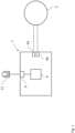
- Fig. 1 shows an emergency lighting device 1 according to an embodiment.
- the emergency lighting device 1 comprises output terminals 5a, 5b for electrically supplying an emergency lighting means 2; a port 9 for receiving communication signals, wherein a test switch 11 is connectable to the port 9, wherein the port 9 is configured to receive selective test start signals from the test switch 11 and is further configured to receive non-test start related communication signals from the test switch 11.
- the emergency lighting device 1 further comprises a controller 6 configured to discriminate the communication signals received at the port 9 in order to correspondingly process the received data as test start signal data or other data.
- the emergency lighting device 1 can be a driver or other control gear of the emergency lighting means 2.
- the emergency lighting means 2 can be an emergency luminaire, in particular an emergency light or an illuminated escape sign.
- the emergency lighting means 2 can comprise an LED light source, e.g. an LED module or an LED track, a sensor, e.g. a motion, a smoke or a light sensor, a control unit or a user interface, e.g. a dimmer or a touchscreen.
- the output terminals 5a, 5b can be connection pins on the housing of the emergency lighting device 1 for electrically connecting the emergency lighting means 2.
- the test switch 11 can be a pushbutton as shown in Fig. 1 .
- the test switch 11 can be arranged directly on a housing of the emergency lighting device 1.
- the test switch 11 can be connected to the port 9 via a wire.
- the controller 6 can be connected to the port 9 and can be designed to process a signal coming from the port 9 either as a test start signal, i.e. a start signal for a test program / test routine, or as other (input) data.
- the controller 6 can further be configured to demodulate the non-test start related data.
- the controller 6 is an ASIC or a microcontroller.
- the emergency lighting device 1, in particular the controller 6, can be configured to initiate a test routine of the device 1 or the connected emergency lighting means 2 upon receipt of the test start signal.
- the port 9 is configured to receive the non-test start related communication signals from the test switch 11.
- the test switch 11 can be activated according to a predefined operation pattern, which differs from a pattern of a test start signal.
- the predefined operation pattern can be defined by time durations and/or by repetition criteria, e.g. pressing the switch 11 for a certain time interval or a certain number of times.
- the port 9 can be configured to receive a communication signal from the test switch 11, which comprises this predefined pattern, and the controller 6 can be configured to process, in particular interpret and/or demodulate, such a signal to generate input data.
- the port 9 can be configured to receive the non-test start related communication signals from the test switch 11 following a power up of the emergency lighting device 1.
- the port 9 is configured to output communication signals.
- the outputted communication signals can comprise status signals or black box data of the emergency lighting device 1.
- the controller 6 is configured to control the port 9 to output the communication signals.
- the communication signals can be outputted to an external device connected to the port 9. In this, a two-way communication can be established via the port 9.
- the non-test start related communication signals received at the port 9 may comprise various types of input data, such as: setting data for setting a mode or operation parameter of the device 1, programming data, or commissioning data.
- the controller 6 can be configured to demodulate and/or process this data.
- the controller 6 can be configured to adjust an operation parameter of the emergency lighting device 1 and/or the emergency lighting means 2 based on the input data. Adjusting an operation parameter can comprise selecting a maintained or non-maintained mode of the device 1, or setting an operation time of the device 1 upon a mains failure. The operation time can, for instance, be set to 1 or 3 hours depending on the requirements.
- the controller 6 can further be configured to program, reprogram or commission the emergency lighting device 1 and/or the emergency lighting means 2 based on the input data.
- the emergency lighting device 1 may comprise a memory for storing the adjusted setting, programming and/or commissioning data.
- the emergency lighting device 1 comprises a visual status indicator (not shown).
- the visual status indicator can be configured to signal the starting of the test routine or the receipt of non-test start related data, e.g. by changing to another color and/or flashing with a certain frequency.
- the visual status indicator is connected to the port 9.
- an emergency lighting system comprises the emergency lighting device 1, the emergency lighting means 2 and the test switch 11.
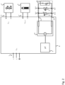
- Fig. 2 shows a block diagram of the emergency lighting device 1 according to another embodiment.
- the emergency lighting device 1 shown in Fig. 2 is a driver which supplies the emergency lighting means 2, in particular an LED module, with a DC output voltage U DC .
- the LED module is connected to the output terminals 5 of the emergency lighting device 1.
- the LED module can include LEDs for an emergency lighting operation.
- the port of the emergency lighting device can be formed by a first connection 9.1 and a second connection 9.1.
- the test switch 11 can be connected between the these connections 9.1, 9.2 in such a way, that the test switch 11 shorts the connections 9.1, 9.2 if it is closed.
- the test switch 11 is a rocker switch.
- the emergency lighting device 1 shown in Fig. 2 further comprises a first LED 12 and a second LED 13, wherein first and second LED 13 are connected in opposite directions in parallel between the first and the second connection 9.1, 9.2.
- Each of the LEDs 12, 13 comprises two connectors 12.1, 12.2 and 13.1, 13.2 forming anode and cathode, respectively.
- the emergency lighting device 1 further comprises a constant power source 10, which is configured to generate a constant current with a first or second polarity between the first and second connection 9.1, 9.2. Depending on the polarity of the constant current, either the first LED 12 or the second LED 13 is illuminated.
- the LEDs 12, 13 can form status LEDs of the device 1. For instance, the first LED 12 is red and the second LED 13 is green. Connecting both LEDs 12, 13 and the test switch 11 to the same port has the advantage that the overall complexity of the device 1 is reduced.
- the LEDs 12, 13 connected to the port connections 9.1, 9.2 can be used to output communication signals by encoding such signals in a signaling characteristic of the LEDs 12, 13, e.g. a flash rate of the LEDs 12, 13.
- the controller 6, in particular a microcontroller, can be configured to detect a short-circuit between the first and the second connection 9.1, 9.2 of the port, for instance by detecting if for a certain constant current, a voltage between the connections 9.1, 9.2 falls below a certain threshold. In this way, the controller 6 can detect if the test switch 11 is opened or closed.
- the test switch 11 can be replaced by a removable jumper link.
- a jumper link is not needed if the device 1 is set to maintained or non-maintained mode by activating the test switch 11 according to predefined operation patterns as disclosed above.
- the emergency lighting device 1 can further comprise a battery connection 7 to which an accumulator 4 or battery is connected.
- the accumulator 4 can be electrically charged by the device 1 via the battery connection 7.
- the device 1 can supply the connector 5 and, thus, the LED module 2 with electrical energy from the accumulator 4, e.g. for an operation time of 1 or 3 hours.
- the operation time can be preset by a communication signal received via the port 9.
- the emergency lighting device 1 can be set to non-maintained mode, where the emergency lighting device 1 only drives the emergency lighting means 2 to light up if a mains power fails, or to maintained mode, where the emergency lighting device 1 is configured to drive the emergency lighting means 2 to light up continuously.
- the emergency lighting device 1 can comprise a further connector 3 for connecting it to the mains.
- Fig. 3 shows a schematic diagram of a method 30 for operating the emergency lighting device 1 according to an embodiment.
- the method 30 comprises the steps of:
- the emergency lighting device 1 can be configured to initiate the test routine of the emergency lighting device 1 and/or the emergency lighting means 2 upon receiving the test start signal.
- method 30 further comprises the step of: outputting communication signals, in particular status signals or black box data, from the port 9.
- the non-test start related communication signals received at the port 9 may comprise setting data.
- the method can comprise the following further step:
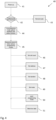
- Fig. 4 shows a schematic diagram of a method 40 for programming and/or commissioning an emergency lighting device 1 according to an embodiment.
- the method 30 for operating the emergency lighting device as for example shown in Fig. 3 , comprises the method 40 or individual steps of the method 40 shown in Fig. 4 .
- the method 40 is performed if the non-test start related communication signals received at the port 9 comprise programming data and/or commissioning data.
- the method 40 comprises: powering-up 41 the emergency lighting device 1, and programming 42 a test sequence.
- the test sequence can be programmed by activating the test switch 11 according to an operation pattern either to activate 43 a normal operating mode of the device 1, or to activate 44 a commissioning mode of the device 1.
- the commissioning mode is activated if the switch 11 is activated according a predefined operation patter.
- the predefined operation pattern can comprise a defined sequence, e.g. a long press followed by a number of short presses on the test switch 1.
- the emergency lighting device 1 may comprise a visual status indicator, e.g. an LED, with gives an optical feedback upon entering the commissioning mode.
- the method 40 can further comprise entering 45 further programming modes by activating the test switch 11 according to further operation patterns, e.g. defined by pressing the switch 11 according to predefined sequences.
- the further programming modes can comprise modes for: setting 46 a cell count, setting 47 an address, in particular of the emergency lighting device 1 or the lighting means 2, setting 48 a duration, in particular an operation duration of the emergency lighting device or the lighting means 2, setting 49 a mode of the emergency lighting device 1, setting 50 and EXIT programming mode of the emergency lighting device 1, or transmitting 51 black box data.
- the visual status indicator can be configured to optically feedback the set mode, for instance by red or green flashes.
- data, such as black box data, of the emergency lighting device 1 can be read out by reading status indicator flash rates, e.g. via a mobile phone app.
Landscapes
- Business, Economics & Management (AREA)
- Emergency Management (AREA)
- Engineering & Computer Science (AREA)
- Power Engineering (AREA)
- Circuit Arrangement For Electric Light Sources In General (AREA)
Description
- The invention relates to an emergency lighting device for supplying an emergency lighting means and to a method for operating such an emergency lighting device.
- Emergency lighting systems enable a quick and safe evacuation of buildings in an emergency situation, for instance during a fire alarm. Such systems usually comprise a plurality of emergency luminaires and associated control gear, e.g. drivers, which are installed in different places in the building.
- Typically, such emergency control gear comprises a test switch for initiating a test sequence of the gear. The test switch can be connected to a dedicated port on the gear. A driver for emergency lighting means comprising such a test switch is, for instance, disclosed in document
DE 20 2016 007 323 U1 . - The document
EP 3 541 147 A1 discloses an emergency luminaire comprising a housing having a base body and a power management unit arranged in the base body and connected to an emergency power source. The emergency luminaire further comprises a first light source and a second light source with different lighting characteristics compared to the first light source. Furthermore, the power management unit comprises at least one controller programmable between several configurations, each configuration corresponding to a specific distribution of the energy provided by at least the emergency power source between the first and second light sources. - The
document EP 1 467 465 A2 discloses a method and a device for secure emergency lighting of tunnels, preferably of railway tunnels in case of a danger, wherein all tunnel lights and devices are thereby monitored. - The document
US 2018/0019615 A1 discloses an emergency operating arrangement for at least one building technical device comprising a power supply unit, and an emergency supply unit. - Often, the emergency control gear comprises further interfaces, for instance, for setting an operating mode of the gear or for exchanging communication data. This leads to a higher complexity of the gear and increases its overall cost.
- Thus, it is an objective to provide an improved emergency lighting device and an improved method for operating an emergency lighting device. In particular, it is an object to provide an emergency lighting device that can receive different types of signals while having a low complexity and, thus, low production costs.
- The object of the present invention is achieved by the solution provided in the enclosed independent claims. Advantageous implementations of the present invention are further defined in the dependent claims.
- According to a first aspect, the present disclosure relates to an emergency lighting device, comprising: output terminals for electrically supplying an emergency lighting means; a port for receiving communication signals, wherein a test switch is connectable to the port; wherein the port is configured to receive selective test start signals from the test switch and wherein the port is further configured to receive non-test start related communication signals from the test switch; and a controller configured to discriminate the communication signals received at the port in order to correspondingly process the received data as test start signal data or non-test start related communication signal data.
- This achieves the advantage that the emergency lighting device can receive different types of signals via its test switch port. Thus, the complexity of the device can be reduced.
- The emergency lighting device can be a driver for the emergency lighting means. The driver can be a converter or can comprise a converter of the emergency lighting means. In particular, the emergency lighting device can be designed for providing a DC power supply to the emergency lighting means.
- The emergency lighting device can comprise an AC input, for receiving an AC mains voltage, e.g. 230 V and can be configured to detect an emergency situation if the AC mains voltage fails. The emergency lighting device can further comprise or be connected to an electrical energy storage, e.g. a battery, for providing an energy supply to the emergency lighting means during such an emergency situation.
- The emergency lighting means can be an emergency luminaire, in particular an emergency light or an illuminated escape sign. The emergency lighting means can comprise an LED (light emitting diode) light source, e.g. an LED module or an LED track. The emergency lighting means can further comprise a sensor, e.g. a motion, a smoke or a light sensor, a control unit or a user interface, e.g. a dimmer or a touchscreen.
- The output terminals can be connection pins on the housing of the emergency lighting device for electrically connecting the emergency lighting means.
- The test switch can be a pushbutton or a rocker switch. In particular, the port and/or the controller are configured to register for how long or how often the switch is manually activated, e.g. pressed or closed, by a user.
- The port can comprise two pins for connecting the test switch. In particular, the test switch can be configured to short the two pins if the test switch is closed.
- The controller can be configured to discriminate operation events at the port in order to determine if they relate to test start signal data or other data, and to further demodulate the data, in particular the other, non-test start related data. For example, the controller can be a microcontroller or an ASIC of the emergency lighting device.
- In an embodiment, the port is configured to output communication signals, in particular status signals or black box data.
- This achieves the advantage that the port can be used to export data, e.g. to an external device. In particular, a two-way communication with the emergency lighting device can be established via the port.
- In particular, the term black box data refers to data comprising parameters, e.g. operating parameters, measurement values, or sensor readings, which were collected by the emergency lighting means over a period of time and which can be stored in an internal memory of the emergency lighting means.
- Preferably, an external device can be connected to the port for forwarding non-test start related communication signals to the emergency lighting device and/or for receiving communication signals from the emergency lighting device. The external device is for instance, a laptop, a smartphone, or another dedicated communication device.
- Alternatively, a visual status indicator, e.g. an LED, can be connected to the port. The output communication signal can be encoded in a signaling characteristic of the visual status indicator, e.g. a flash rate of the visual status indicator. This encoding is, for instance, performed by the controller. Preferably, the output signal can be read out by an external device, e.g. a smartphone with a dedicated App, which is detecting and decoding the signaling characteristic of the visual status indicator.
- In an embodiment, the non-test start related communication signals received at the port comprise setting data, wherein the controller is configured to adjust an operation parameter of the emergency lighting device and/or the emergency lighting means based on the setting data.
- This achieves the advantage that settings of the emergency lighting device and/or the emergency lighting means can be adapted via the port.
- In an embodiment, the controller is configured to set the emergency lighting device to a maintained mode or a non-maintained mode and/or to set an operation time of the emergency lighting device, in particular an operation time upon a mains failure, based on the setting data.
- This achieves the advantage that operation parameters, such as operation mode or operation time of the emergency lighting device can be set via the port.
- For example, in non-maintained mode the emergency lighting device only drives the emergency lighting means to light up if a mains power fails, while in maintained mode the emergency lighting device is configured to drive the emergency lighting means to light up continuously.
- In an embodiment, the non-test start related communication signals received at the port comprise programming data, wherein the controller is configured to program or reprogram the emergency lighting device and/or the emergency lighting means based on the programming data.
- This achieves the advantage that the emergency lighting device and/or the emergency lighting means can be programmed via the port.
- The non-test start related communication signals received at the port comprise the commissioning data, wherein the controller is configured to commission the emergency lighting device and/or the emergency lighting means based on the commissioning data.
- This achieves the advantage that the emergency lighting device and/or the emergency lighting means can be commissioned via the port.
- In particular, commissioning may refer to assigning the emergency lighting device and/or the emergency lighting means to a group of likewise devices or means and/or to a location in the environment, e.g. a room.
- In an embodiment, the emergency lighting device is configured to initiate a test routine of the emergency lighting device and/or the emergency lighting means upon receiving the test start signal.
- Preferably, during the test routine various functions of the emergency lighting device and/or the emergency lighting means that are to be executed during an emergency situation can be tested, e.g. providing a power supply to the lighting means via a battery, activating the lighting means etc..
- In particular, predefined operation patterns of the test switch can comprise time durations and/or repetition criteria, e.g. pressing the test switch for a predefined duration or a predefined number of times. The controller can be configured to process these operation patterns to determine if they relate to input data and, if yes, to demodulate the input data.
- This achieves the advantage that also non-test start related signals, e.g. signals comprising settings or operation parameters, can be transferred or entered on the emergency lighting device by means of the test switch. Thus, no external device is required for transiting these signals, which further reduces device complexity and leads to cost savings.
- According to a second aspect, the present disclosure relates to a system comprising an emergency lighting means, a test switch and an emergency lighting device according to the first aspect of the present disclosure.
- The system can be an emergency lighting system for an environment such as a building.
- According to a third aspect, the present disclosure relates to a method for operating an emergency lighting device supplying an emergency lighting means, wherein the emergency lighting device comprises a port configured to receive selective test start signals from a test switch connectable to the port and further configured to receive non-test start related communication signals from the test switch, wherein the emergency lighting device further comprises a controller configured to discriminate the communication signals received at the port in order to correspondingly process the received data as test start signal data or non-test start related communication signal data, the method comprising the steps of:
- receiving the selective test start signals from the test switch or the non-test start related communication signals from the test switch at the port; and
- discriminating the communication signals received at the port in order to correspondingly process the received data as the test start signal data or other data.
- This achieves the advantage that the emergency lighting device can receive different types of signals via its test switch port. Thus, the complexity of the device can be reduced.
- Preferably, the emergency lighting means comprises a controller, e.g. a microcontroller or ASIC, which is configured to discriminate the communication signal and/or process the received data.
- In an embodiment, the method further comprises the step:
- outputting communication signals, in particular status signals or black box data, from the port.
- This achieves the advantage that the port can be used to export data, e.g. to an external device. In particular, a two-way communication with the emergency lighting device can be established via the port.
- In an embodiment, the non-test start related communication signals received at the port comprise setting data, wherein the method comprises:
- adjusting an operation parameter of the emergency lighting device and/or the emergency lighting means based on the setting data.
- This achieves the advantage that settings of the emergency lighting device and/or the emergency lighting means can be adapted via the port.
- In an embodiment, the non-test start related communication signals received at the port comprise programming data, wherein the method comprises:
- programming or reprogramming the emergency lighting device and/or the emergency lighting means based on the programming data.
- This achieves the advantage that the emergency lighting device and/or the emergency lighting means can be programmed via the port.
- The non-test start related communication signals received at the port comprise the commissioning data, wherein the method comprises:
- commissioning the emergency lighting device and/or the emergency lighting means based on the commissioning data.
- This achieves the advantage that the emergency lighting device and/or the emergency lighting means can be commissioned via the port.
- In particular, the steps of adjusting the operation parameter, programming, reprogramming, or commissioning can all be carried out by the controller of the emergency lighting device.
- In an embodiment, the emergency lighting device is configured to initiate a test routine of the emergency lighting device and/or the emergency lighting means upon receiving the test start signal.
- The above description with regard to the emergency lighting device according to the first aspect of the present disclosure is correspondingly valid for the method according to the third aspect of the present disclosure.
- The invention will be explained in the followings together with the figures.
- Fig. 1
- shows a block diagram of an emergency lighting device according to an embodiment;
- Fig. 2
- shows a block diagram of an emergency lighting device according to an embodiment;
- Fig. 3
- shows a schematic diagram of a method for operating an emergency lighting device according to an embodiment; and
- Fig. 4
- shows a schematic diagram of a method for programming and/or commissioning an emergency lighting device according to an embodiment.
-
Fig. 1 shows anemergency lighting device 1 according to an embodiment. - The
emergency lighting device 1 comprisesoutput terminals port 9 for receiving communication signals, wherein atest switch 11 is connectable to theport 9, wherein theport 9 is configured to receive selective test start signals from thetest switch 11 and is further configured to receive non-test start related communication signals from thetest switch 11. Theemergency lighting device 1 further comprises acontroller 6 configured to discriminate the communication signals received at theport 9 in order to correspondingly process the received data as test start signal data or other data. - The
emergency lighting device 1 can be a driver or other control gear of the emergency lighting means 2. - The emergency lighting means 2 can be an emergency luminaire, in particular an emergency light or an illuminated escape sign. The emergency lighting means 2 can comprise an LED light source, e.g. an LED module or an LED track, a sensor, e.g. a motion, a smoke or a light sensor, a control unit or a user interface, e.g. a dimmer or a touchscreen.
- The
output terminals emergency lighting device 1 for electrically connecting the emergency lighting means 2. - The
test switch 11 can be a pushbutton as shown inFig. 1 . When connected to theport 9, thetest switch 11 can be arranged directly on a housing of theemergency lighting device 1. Alternatively, thetest switch 11 can be connected to theport 9 via a wire. - The
controller 6 can be connected to theport 9 and can be designed to process a signal coming from theport 9 either as a test start signal, i.e. a start signal for a test program / test routine, or as other (input) data. Thecontroller 6 can further be configured to demodulate the non-test start related data. For example, thecontroller 6 is an ASIC or a microcontroller. - The
emergency lighting device 1, in particular thecontroller 6, can be configured to initiate a test routine of thedevice 1 or the connected emergency lighting means 2 upon receipt of the test start signal. - Preferably, the
port 9 is configured to receive the non-test start related communication signals from thetest switch 11. To forward non-test start related communication signals to theemergency lighting device 1 with thetest switch 11, thetest switch 11 can be activated according to a predefined operation pattern, which differs from a pattern of a test start signal. For instance, the predefined operation pattern can be defined by time durations and/or by repetition criteria, e.g. pressing theswitch 11 for a certain time interval or a certain number of times. Theport 9 can be configured to receive a communication signal from thetest switch 11, which comprises this predefined pattern, and thecontroller 6 can be configured to process, in particular interpret and/or demodulate, such a signal to generate input data. - In particular, the
port 9 can be configured to receive the non-test start related communication signals from thetest switch 11 following a power up of theemergency lighting device 1. - In an optional implementation, the
port 9 is configured to output communication signals. The outputted communication signals can comprise status signals or black box data of theemergency lighting device 1. In particular, thecontroller 6 is configured to control theport 9 to output the communication signals. The communication signals can be outputted to an external device connected to theport 9. In this, a two-way communication can be established via theport 9. - The non-test start related communication signals received at the
port 9 may comprise various types of input data, such as: setting data for setting a mode or operation parameter of thedevice 1, programming data, or commissioning data. - The
controller 6 can be configured to demodulate and/or process this data. In particular, thecontroller 6 can be configured to adjust an operation parameter of theemergency lighting device 1 and/or the emergency lighting means 2 based on the input data. Adjusting an operation parameter can comprise selecting a maintained or non-maintained mode of thedevice 1, or setting an operation time of thedevice 1 upon a mains failure. The operation time can, for instance, be set to 1 or 3 hours depending on the requirements. - The
controller 6 can further be configured to program, reprogram or commission theemergency lighting device 1 and/or the emergency lighting means 2 based on the input data. - The
emergency lighting device 1 may comprise a memory for storing the adjusted setting, programming and/or commissioning data. - Optionally, the
emergency lighting device 1 comprises a visual status indicator (not shown). The visual status indicator can be configured to signal the starting of the test routine or the receipt of non-test start related data, e.g. by changing to another color and/or flashing with a certain frequency. In an optional implementation, the visual status indicator is connected to theport 9. - Preferably, an emergency lighting system comprises the
emergency lighting device 1, the emergency lighting means 2 and thetest switch 11. -
Fig. 2 shows a block diagram of theemergency lighting device 1 according to another embodiment. - The
emergency lighting device 1 shown inFig. 2 is a driver which supplies the emergency lighting means 2, in particular an LED module, with a DC output voltage UDC. The LED module is connected to theoutput terminals 5 of theemergency lighting device 1. The LED module can include LEDs for an emergency lighting operation. The port of the emergency lighting device can be formed by a first connection 9.1 and a second connection 9.1. Thetest switch 11 can be connected between the these connections 9.1, 9.2 in such a way, that thetest switch 11 shorts the connections 9.1, 9.2 if it is closed. For example, thetest switch 11 is a rocker switch. - The
emergency lighting device 1 shown inFig. 2 further comprises a first LED 12 and asecond LED 13, wherein first andsecond LED 13 are connected in opposite directions in parallel between the first and the second connection 9.1, 9.2. Each of theLEDs 12, 13 comprises two connectors 12.1, 12.2 and 13.1, 13.2 forming anode and cathode, respectively. - In the exemplary embodiment of
Fig. 2 , theemergency lighting device 1 further comprises aconstant power source 10, which is configured to generate a constant current with a first or second polarity between the first and second connection 9.1, 9.2. Depending on the polarity of the constant current, either the first LED 12 or thesecond LED 13 is illuminated. TheLEDs 12, 13 can form status LEDs of thedevice 1. For instance, the first LED 12 is red and thesecond LED 13 is green. Connecting bothLEDs 12, 13 and thetest switch 11 to the same port has the advantage that the overall complexity of thedevice 1 is reduced. - In particular, the
LEDs 12, 13 connected to the port connections 9.1, 9.2 can be used to output communication signals by encoding such signals in a signaling characteristic of theLEDs 12, 13, e.g. a flash rate of theLEDs 12, 13. - The
controller 6, in particular a microcontroller, can be configured to detect a short-circuit between the first and the second connection 9.1, 9.2 of the port, for instance by detecting if for a certain constant current, a voltage between the connections 9.1, 9.2 falls below a certain threshold. In this way, thecontroller 6 can detect if thetest switch 11 is opened or closed. - In particular, to set the
emergency lighting device 1 to maintained or non-maintained mode, thetest switch 11 can be replaced by a removable jumper link. However, such a jumper link is not needed if thedevice 1 is set to maintained or non-maintained mode by activating thetest switch 11 according to predefined operation patterns as disclosed above. - The
emergency lighting device 1 can further comprise a battery connection 7 to which an accumulator 4 or battery is connected. The accumulator 4 can be electrically charged by thedevice 1 via the battery connection 7. In an emergency situation (e.g. failure of the mains voltage UAC), thedevice 1 can supply theconnector 5 and, thus, theLED module 2 with electrical energy from the accumulator 4, e.g. for an operation time of 1 or 3 hours. The operation time can be preset by a communication signal received via theport 9. - The
emergency lighting device 1 can be set to non-maintained mode, where theemergency lighting device 1 only drives the emergency lighting means 2 to light up if a mains power fails, or to maintained mode, where theemergency lighting device 1 is configured to drive the emergency lighting means 2 to light up continuously. - The
emergency lighting device 1 can comprise a further connector 3 for connecting it to the mains. -
Fig. 3 shows a schematic diagram of amethod 30 for operating theemergency lighting device 1 according to an embodiment. - The
method 30 comprises the steps of: - receiving 31 selective test start signals from the
test switch 11 or non-test start related communication signals from thetest switch 11 at theport 9; and - discriminating 32 the communication signals received at the
port 9 in order to correspondingly process the received data as test start signal data or other data. - The
emergency lighting device 1 can be configured to initiate the test routine of theemergency lighting device 1 and/or the emergency lighting means 2 upon receiving the test start signal. - Preferably,
method 30 further comprises the step of: outputting communication signals, in particular status signals or black box data, from theport 9. - The non-test start related communication signals received at the
port 9 may comprise setting data. In this case, the method can comprise the following further step: - adjusting an operation parameter of the
emergency lighting device 1 and/or the emergency lighting means 2 based on the setting data. -
Fig. 4 shows a schematic diagram of amethod 40 for programming and/or commissioning anemergency lighting device 1 according to an embodiment. In particular, themethod 30 for operating the emergency lighting device, as for example shown inFig. 3 , comprises themethod 40 or individual steps of themethod 40 shown inFig. 4 . - Preferably, the
method 40 is performed if the non-test start related communication signals received at theport 9 comprise programming data and/or commissioning data. - The
method 40 comprises: powering-up 41 theemergency lighting device 1, and programming 42 a test sequence. The test sequence can be programmed by activating thetest switch 11 according to an operation pattern either to activate 43 a normal operating mode of thedevice 1, or to activate 44 a commissioning mode of thedevice 1. Preferably, the commissioning mode is activated if theswitch 11 is activated according a predefined operation patter. The predefined operation pattern can comprise a defined sequence, e.g. a long press followed by a number of short presses on thetest switch 1. Furthermore, theemergency lighting device 1 may comprise a visual status indicator, e.g. an LED, with gives an optical feedback upon entering the commissioning mode. - Following activating 44 the commission mode, the
method 40 can further comprise entering 45 further programming modes by activating thetest switch 11 according to further operation patterns, e.g. defined by pressing theswitch 11 according to predefined sequences. - The further programming modes can comprise modes for: setting 46 a cell count, setting 47 an address, in particular of the
emergency lighting device 1 or the lighting means 2, setting 48 a duration, in particular an operation duration of the emergency lighting device or the lighting means 2, setting 49 a mode of theemergency lighting device 1, setting 50 and EXIT programming mode of theemergency lighting device 1, or transmitting 51 black box data. - The visual status indicator can be configured to optically feedback the set mode, for instance by red or green flashes. In addition, data, such as black box data, of the
emergency lighting device 1 can be read out by reading status indicator flash rates, e.g. via a mobile phone app. - While various embodiments of the present invention have been described above, it should be understood that they have been presented by way of example only and not limitation. Numerous changes to the disclosed embodiments can be made in accordance with the disclosure herein without departing from the scope of the invention. Thus, the breadth and scope of the present invention should not be limited by any of the above-described embodiments. Rather, the scope of the invention should be defined in accordance with the following claims and their equivalence.
- Although the invention has been illustrated and described with respect to one or more implementations, equivalent alternations and modifications will occur to those skilled in the art upon the reading of the understanding of the specification and the annexed drawings.
Claims (12)
- Emergency lighting device (1), comprising:
output terminals (5a, 5b) for electrically supplying an emergency lighting means (2);a port (9) for receiving communication signals, wherein a test switch (11) is connectable to the port (9);wherein the port (9) is configured to receive selective test start signals from the test switch (11) and wherein the port (9) is further configured to receive non-test start related communication signals from the test switch (11); anda controller (6) configured to discriminate the communication signals received at the port (9) in order to correspondingly process the received data as test start signal data or non-test start related communication signal data;the emergency lighting device (1) beingcharacterized in thatthe non-test start related communication signals received at the port (9) comprise commissioning data; andthe controller (6) is configured to commission the emergency lighting device (1) and/or the emergency lighting means (2) based on the commissioning data. - Emergency lighting device (1) according to claim 1, wherein the port (9) is configured to output communication signals, in particular status signals or black box data.
- Emergency lighting device (1) according to claim 1 or 2, wherein the non-test start related communication signals received at the port (9) comprise setting data, wherein the controller (6) is configured to adjust an operation parameter of the emergency lighting device (1) and/or the emergency lighting means (2) based on the setting data.
- Emergency lighting device (1) according to claim 3, wherein the controller (6) is configured to set the emergency lighting device (1) to a maintained mode or a non-maintained mode and/or to set an operation time of the emergency lighting device (1), in particular an operation time upon a mains failure, based on the setting data.
- Emergency lighting device (1) according to any one of the preceding claims, wherein the non-test start related communication signals received at the port (9) comprise programming data, wherein the controller (6) is configured to program or reprogram the emergency lighting device (1) and/or the emergency lighting means (2) based on the programming data.
- Emergency lighting device (1) according to any one of the preceding claims, wherein the emergency lighting device (1) is configured to initiate a test routine of the emergency lighting device (1) and/or the emergency lighting means (2) upon receiving the test start signal.
- System comprising an emergency lighting means (2), a test switch (11) and an emergency lighting device (1) according to any one of the preceding claims.
- Method (30) for operating an emergency lighting device (1) supplying an emergency lighting means (2), wherein the emergency lighting device (1) comprises a port (9) for receiving communication signals, wherein the port (9) is configured to receive selective test start signals from a test switch (11) connectable to the port (9) and further configured to receive non-test start related communication signals from the test switch (11), wherein the emergency lighting device (1) further comprises a controller (6) configured to discriminate the communication signals received at the port (9) in order to correspondingly process the received data as test start signal data or non-test start related communication signal data, the method (30) comprising the steps of:• receiving (31) the selective test start signals or the non-test start related communication signals from the test switch (11) at the port (9);• discriminating (32) the communication signals received at the port (9) in order to correspondingly process the received data as the test start signal data or the other data; andthe method being characterized in thatthe non-test start related communication signals received at the port (9) comprise commissioning data; and the method (30) further comprises:• commissioning the emergency lighting device (1) and/or the emergency lighting means (2) based on the commissioning data.
- Method (30) according to claim 8, further comprising the step:• outputting communication signals, in particular status signals or black box data, from the port (9).
- Method (30) according to claim 8 or 9, wherein the non-test start related communication signals received at the port (9) comprise setting data, wherein the method (30) further comprises the step:• adjusting an operation parameter of the emergency lighting device (1) and/or the emergency lighting means (2) based on the setting data.
- Method (30) according to any one of claims 8 to 10, wherein the non-test start related communication signals received at the port (9) comprise programming data, wherein the method (30) further comprises the step:• programming or reprogramming the emergency lighting device (1) and/or the emergency lighting means (2) based on the programming data.
- Method (30) according to any one of claims 8 to 11, wherein the emergency lighting device (1) is configured to initiate a test routine of the emergency lighting device (1) and/or the emergency lighting means (2) upon receiving the test start signal.
Priority Applications (2)
| Application Number | Priority Date | Filing Date | Title |
|---|---|---|---|
| EP20173792.1A EP3910754B1 (en) | 2020-05-11 | 2020-05-11 | Emergency lighting device |
| PCT/EP2021/060447 WO2021228522A1 (en) | 2020-05-11 | 2021-04-21 | Emergency lighting device |
Applications Claiming Priority (1)
| Application Number | Priority Date | Filing Date | Title |
|---|---|---|---|
| EP20173792.1A EP3910754B1 (en) | 2020-05-11 | 2020-05-11 | Emergency lighting device |
Publications (2)
| Publication Number | Publication Date |
|---|---|
| EP3910754A1 EP3910754A1 (en) | 2021-11-17 |
| EP3910754B1 true EP3910754B1 (en) | 2024-11-06 |
Family
ID=70680334
Family Applications (1)
| Application Number | Title | Priority Date | Filing Date |
|---|---|---|---|
| EP20173792.1A Active EP3910754B1 (en) | 2020-05-11 | 2020-05-11 | Emergency lighting device |
Country Status (2)
| Country | Link |
|---|---|
| EP (1) | EP3910754B1 (en) |
| WO (1) | WO2021228522A1 (en) |
Families Citing this family (2)
| Publication number | Priority date | Publication date | Assignee | Title |
|---|---|---|---|---|
| EP4271140B1 (en) * | 2022-04-29 | 2025-01-29 | Tridonic GmbH & Co. KG | Emergency driver for an emergency luminaire |
| EP4422352A1 (en) * | 2023-02-21 | 2024-08-28 | Tridonic GmbH & Co. KG | Entity and method for controlling a status indicator associated with an emergency lighting means driver |
Family Cites Families (6)
| Publication number | Priority date | Publication date | Assignee | Title |
|---|---|---|---|---|
| GB9904518D0 (en) * | 1999-02-27 | 1999-04-21 | Emergi Lite Safety Systems Lim | Improvements relating to emergency lighting units and installations |
| GB9907610D0 (en) * | 1999-04-06 | 1999-05-26 | Crompton Lighting Limited | Emergency lighting unit with remote handset |
| DE10316008B4 (en) * | 2003-04-07 | 2007-12-20 | Db Netz Ag | Method and device for safe emergency lighting of tunnels |
| GB2535807B (en) * | 2015-02-24 | 2021-02-24 | Tridonic Gmbh & Co Kg | Emergency supply unit |
| DE202016007323U1 (en) | 2016-11-30 | 2018-03-02 | Tridonic Gmbh & Co. Kg | Operating unit with test switch and status display |
| GB2576689A (en) * | 2018-03-16 | 2020-03-04 | Eaton Intelligent Power Ltd | Configurable emergency luminaire |
-
2020
- 2020-05-11 EP EP20173792.1A patent/EP3910754B1/en active Active
-
2021
- 2021-04-21 WO PCT/EP2021/060447 patent/WO2021228522A1/en not_active Ceased
Also Published As
| Publication number | Publication date |
|---|---|
| WO2021228522A1 (en) | 2021-11-18 |
| EP3910754A1 (en) | 2021-11-17 |
Similar Documents
| Publication | Publication Date | Title |
|---|---|---|
| US10111308B2 (en) | System for and method of commissioning lighting devices within a wireless network | |
| CN104395668B (en) | lighting device | |
| CN101854763B (en) | Lighting Control Assembly | |
| EP3501240B1 (en) | Lighting device for powering from a main power supply and an auxiliary power supply | |
| KR102064369B1 (en) | Lighting control device and lighting device having the same | |
| EP3910754B1 (en) | Emergency lighting device | |
| CN106105397B (en) | Lighting system, lamp and method for emergency lighting operation in a lighting system | |
| US11743996B1 (en) | Load control system comprising linear lighting fixtures | |
| CN204929348U (en) | An intelligent lighting control system | |
| US20240138044A1 (en) | Testing method and controller for controlling testing method | |
| CN103891410B (en) | Addressing method for lighting equipment operating devices | |
| US10448484B1 (en) | Integrated digital lighting controller | |
| CN105165125B (en) | LED operating device | |
| EP4066599B1 (en) | Driver for emergency lighting means | |
| JP2016081701A (en) | Lighting fixture | |
| CN209120512U (en) | A kind of the power-on self-test system and DMX lamps and lanterns of DMX lamps and lanterns | |
| US20220191992A1 (en) | Duration select switch for an emergency lighting converter | |
| CN207674296U (en) | Emergency lighting and exit signs detecting system | |
| US12249865B2 (en) | Modular emergency battery | |
| JP7500820B1 (en) | Lighting system and wireless module | |
| EP2942763B1 (en) | Emergency illumination system and visual alarm therefor | |
| JP2024158028A (en) | Remote controller and lighting system | |
| KR20250034505A (en) | Fire Safety Device Address and Location Verification | |
| CN111885780A (en) | Intelligence UVLED lamps and lanterns |
Legal Events
| Date | Code | Title | Description |
|---|---|---|---|
| PUAI | Public reference made under article 153(3) epc to a published international application that has entered the european phase |
Free format text: ORIGINAL CODE: 0009012 |
|
| STAA | Information on the status of an ep patent application or granted ep patent |
Free format text: STATUS: THE APPLICATION HAS BEEN PUBLISHED |
|
| AK | Designated contracting states |
Kind code of ref document: A1 Designated state(s): AL AT BE BG CH CY CZ DE DK EE ES FI FR GB GR HR HU IE IS IT LI LT LU LV MC MK MT NL NO PL PT RO RS SE SI SK SM TR |
|
| B565 | Issuance of search results under rule 164(2) epc |
Effective date: 20200929 |
|
| STAA | Information on the status of an ep patent application or granted ep patent |
Free format text: STATUS: REQUEST FOR EXAMINATION WAS MADE |
|
| 17P | Request for examination filed |
Effective date: 20220503 |
|
| RBV | Designated contracting states (corrected) |
Designated state(s): AL AT BE BG CH CY CZ DE DK EE ES FI FR GB GR HR HU IE IS IT LI LT LU LV MC MK MT NL NO PL PT RO RS SE SI SK SM TR |
|
| STAA | Information on the status of an ep patent application or granted ep patent |
Free format text: STATUS: EXAMINATION IS IN PROGRESS |
|
| 17Q | First examination report despatched |
Effective date: 20230503 |
|
| REG | Reference to a national code |
Ref country code: DE Ref legal event code: R079 Free format text: PREVIOUS MAIN CLASS: H02J0009060000 Ipc: H05B0047170000 Ref country code: DE Ref legal event code: R079 Ref document number: 602020040669 Country of ref document: DE Free format text: PREVIOUS MAIN CLASS: H02J0009060000 Ipc: H05B0047170000 |
|
| GRAP | Despatch of communication of intention to grant a patent |
Free format text: ORIGINAL CODE: EPIDOSNIGR1 |
|
| STAA | Information on the status of an ep patent application or granted ep patent |
Free format text: STATUS: GRANT OF PATENT IS INTENDED |
|
| RIC1 | Information provided on ipc code assigned before grant |
Ipc: H05B 47/175 20200101ALI20240529BHEP Ipc: H02J 9/02 20060101ALI20240529BHEP Ipc: H05B 47/18 20200101ALI20240529BHEP Ipc: H05B 47/17 20200101AFI20240529BHEP |
|
| INTG | Intention to grant announced |
Effective date: 20240620 |
|
| P01 | Opt-out of the competence of the unified patent court (upc) registered |
Free format text: CASE NUMBER: APP_44193/2024 Effective date: 20240730 |
|
| GRAS | Grant fee paid |
Free format text: ORIGINAL CODE: EPIDOSNIGR3 |
|
| GRAA | (expected) grant |
Free format text: ORIGINAL CODE: 0009210 |
|
| STAA | Information on the status of an ep patent application or granted ep patent |
Free format text: STATUS: THE PATENT HAS BEEN GRANTED |
|
| AK | Designated contracting states |
Kind code of ref document: B1 Designated state(s): AL AT BE BG CH CY CZ DE DK EE ES FI FR GB GR HR HU IE IS IT LI LT LU LV MC MK MT NL NO PL PT RO RS SE SI SK SM TR |
|
| REG | Reference to a national code |
Ref country code: GB Ref legal event code: FG4D |
|
| REG | Reference to a national code |
Ref country code: CH Ref legal event code: EP |
|
| REG | Reference to a national code |
Ref country code: DE Ref legal event code: R096 Ref document number: 602020040669 Country of ref document: DE |
|
| REG | Reference to a national code |
Ref country code: IE Ref legal event code: FG4D |
|
| REG | Reference to a national code |
Ref country code: DE Ref legal event code: R084 Ref document number: 602020040669 Country of ref document: DE |
|
| REG | Reference to a national code |
Ref country code: LT Ref legal event code: MG9D |
|
| REG | Reference to a national code |
Ref country code: NL Ref legal event code: MP Effective date: 20241106 |
|
| PG25 | Lapsed in a contracting state [announced via postgrant information from national office to epo] |
Ref country code: HR Free format text: LAPSE BECAUSE OF FAILURE TO SUBMIT A TRANSLATION OF THE DESCRIPTION OR TO PAY THE FEE WITHIN THE PRESCRIBED TIME-LIMIT Effective date: 20241106 Ref country code: PT Free format text: LAPSE BECAUSE OF FAILURE TO SUBMIT A TRANSLATION OF THE DESCRIPTION OR TO PAY THE FEE WITHIN THE PRESCRIBED TIME-LIMIT Effective date: 20250306 Ref country code: IS Free format text: LAPSE BECAUSE OF FAILURE TO SUBMIT A TRANSLATION OF THE DESCRIPTION OR TO PAY THE FEE WITHIN THE PRESCRIBED TIME-LIMIT Effective date: 20250306 |
|
| PG25 | Lapsed in a contracting state [announced via postgrant information from national office to epo] |
Ref country code: NL Free format text: LAPSE BECAUSE OF FAILURE TO SUBMIT A TRANSLATION OF THE DESCRIPTION OR TO PAY THE FEE WITHIN THE PRESCRIBED TIME-LIMIT Effective date: 20241106 Ref country code: FI Free format text: LAPSE BECAUSE OF FAILURE TO SUBMIT A TRANSLATION OF THE DESCRIPTION OR TO PAY THE FEE WITHIN THE PRESCRIBED TIME-LIMIT Effective date: 20241106 |
|
| REG | Reference to a national code |
Ref country code: AT Ref legal event code: MK05 Ref document number: 1740823 Country of ref document: AT Kind code of ref document: T Effective date: 20241106 |
|
| PG25 | Lapsed in a contracting state [announced via postgrant information from national office to epo] |
Ref country code: BG Free format text: LAPSE BECAUSE OF FAILURE TO SUBMIT A TRANSLATION OF THE DESCRIPTION OR TO PAY THE FEE WITHIN THE PRESCRIBED TIME-LIMIT Effective date: 20241106 |
|
| PG25 | Lapsed in a contracting state [announced via postgrant information from national office to epo] |
Ref country code: ES Free format text: LAPSE BECAUSE OF FAILURE TO SUBMIT A TRANSLATION OF THE DESCRIPTION OR TO PAY THE FEE WITHIN THE PRESCRIBED TIME-LIMIT Effective date: 20241106 |
|
| PG25 | Lapsed in a contracting state [announced via postgrant information from national office to epo] |
Ref country code: NO Free format text: LAPSE BECAUSE OF FAILURE TO SUBMIT A TRANSLATION OF THE DESCRIPTION OR TO PAY THE FEE WITHIN THE PRESCRIBED TIME-LIMIT Effective date: 20250206 |
|
| PG25 | Lapsed in a contracting state [announced via postgrant information from national office to epo] |
Ref country code: LV Free format text: LAPSE BECAUSE OF FAILURE TO SUBMIT A TRANSLATION OF THE DESCRIPTION OR TO PAY THE FEE WITHIN THE PRESCRIBED TIME-LIMIT Effective date: 20241106 Ref country code: GR Free format text: LAPSE BECAUSE OF FAILURE TO SUBMIT A TRANSLATION OF THE DESCRIPTION OR TO PAY THE FEE WITHIN THE PRESCRIBED TIME-LIMIT Effective date: 20250207 Ref country code: AT Free format text: LAPSE BECAUSE OF FAILURE TO SUBMIT A TRANSLATION OF THE DESCRIPTION OR TO PAY THE FEE WITHIN THE PRESCRIBED TIME-LIMIT Effective date: 20241106 |
|
| PG25 | Lapsed in a contracting state [announced via postgrant information from national office to epo] |
Ref country code: PL Free format text: LAPSE BECAUSE OF FAILURE TO SUBMIT A TRANSLATION OF THE DESCRIPTION OR TO PAY THE FEE WITHIN THE PRESCRIBED TIME-LIMIT Effective date: 20241106 |
|
| PG25 | Lapsed in a contracting state [announced via postgrant information from national office to epo] |
Ref country code: RS Free format text: LAPSE BECAUSE OF FAILURE TO SUBMIT A TRANSLATION OF THE DESCRIPTION OR TO PAY THE FEE WITHIN THE PRESCRIBED TIME-LIMIT Effective date: 20250206 |
|
| PG25 | Lapsed in a contracting state [announced via postgrant information from national office to epo] |
Ref country code: SM Free format text: LAPSE BECAUSE OF FAILURE TO SUBMIT A TRANSLATION OF THE DESCRIPTION OR TO PAY THE FEE WITHIN THE PRESCRIBED TIME-LIMIT Effective date: 20241106 |
|
| PGFP | Annual fee paid to national office [announced via postgrant information from national office to epo] |
Ref country code: DE Payment date: 20250528 Year of fee payment: 6 |
|
| PG25 | Lapsed in a contracting state [announced via postgrant information from national office to epo] |
Ref country code: DK Free format text: LAPSE BECAUSE OF FAILURE TO SUBMIT A TRANSLATION OF THE DESCRIPTION OR TO PAY THE FEE WITHIN THE PRESCRIBED TIME-LIMIT Effective date: 20241106 |
|
| PG25 | Lapsed in a contracting state [announced via postgrant information from national office to epo] |
Ref country code: EE Free format text: LAPSE BECAUSE OF FAILURE TO SUBMIT A TRANSLATION OF THE DESCRIPTION OR TO PAY THE FEE WITHIN THE PRESCRIBED TIME-LIMIT Effective date: 20241106 |
|
| PGFP | Annual fee paid to national office [announced via postgrant information from national office to epo] |
Ref country code: FR Payment date: 20250526 Year of fee payment: 6 |
|
| PG25 | Lapsed in a contracting state [announced via postgrant information from national office to epo] |
Ref country code: RO Free format text: LAPSE BECAUSE OF FAILURE TO SUBMIT A TRANSLATION OF THE DESCRIPTION OR TO PAY THE FEE WITHIN THE PRESCRIBED TIME-LIMIT Effective date: 20241106 |
|
| PG25 | Lapsed in a contracting state [announced via postgrant information from national office to epo] |
Ref country code: SK Free format text: LAPSE BECAUSE OF FAILURE TO SUBMIT A TRANSLATION OF THE DESCRIPTION OR TO PAY THE FEE WITHIN THE PRESCRIBED TIME-LIMIT Effective date: 20241106 |
|
| PG25 | Lapsed in a contracting state [announced via postgrant information from national office to epo] |
Ref country code: CZ Free format text: LAPSE BECAUSE OF FAILURE TO SUBMIT A TRANSLATION OF THE DESCRIPTION OR TO PAY THE FEE WITHIN THE PRESCRIBED TIME-LIMIT Effective date: 20241106 |
|
| PG25 | Lapsed in a contracting state [announced via postgrant information from national office to epo] |
Ref country code: IT Free format text: LAPSE BECAUSE OF FAILURE TO SUBMIT A TRANSLATION OF THE DESCRIPTION OR TO PAY THE FEE WITHIN THE PRESCRIBED TIME-LIMIT Effective date: 20241106 |
|
| REG | Reference to a national code |
Ref country code: DE Ref legal event code: R097 Ref document number: 602020040669 Country of ref document: DE |
|
| PG25 | Lapsed in a contracting state [announced via postgrant information from national office to epo] |
Ref country code: SE Free format text: LAPSE BECAUSE OF FAILURE TO SUBMIT A TRANSLATION OF THE DESCRIPTION OR TO PAY THE FEE WITHIN THE PRESCRIBED TIME-LIMIT Effective date: 20241106 |
|
| PLBE | No opposition filed within time limit |
Free format text: ORIGINAL CODE: 0009261 |
|
| STAA | Information on the status of an ep patent application or granted ep patent |
Free format text: STATUS: NO OPPOSITION FILED WITHIN TIME LIMIT |
|
| 26N | No opposition filed |
Effective date: 20250807 |
|
| REG | Reference to a national code |
Ref country code: CH Ref legal event code: H13 Free format text: ST27 STATUS EVENT CODE: U-0-0-H10-H13 (AS PROVIDED BY THE NATIONAL OFFICE) Effective date: 20251223 |
|
| PG25 | Lapsed in a contracting state [announced via postgrant information from national office to epo] |
Ref country code: LU Free format text: LAPSE BECAUSE OF NON-PAYMENT OF DUE FEES Effective date: 20250511 |
|
| PG25 | Lapsed in a contracting state [announced via postgrant information from national office to epo] |
Ref country code: CH Free format text: LAPSE BECAUSE OF NON-PAYMENT OF DUE FEES Effective date: 20250531 |
|
| REG | Reference to a national code |
Ref country code: BE Ref legal event code: MM Effective date: 20250531 |
|
| PG25 | Lapsed in a contracting state [announced via postgrant information from national office to epo] |
Ref country code: MC Free format text: LAPSE BECAUSE OF FAILURE TO SUBMIT A TRANSLATION OF THE DESCRIPTION OR TO PAY THE FEE WITHIN THE PRESCRIBED TIME-LIMIT Effective date: 20241106 |
|
| PGFP | Annual fee paid to national office [announced via postgrant information from national office to epo] |
Ref country code: GB Payment date: 20260304 Year of fee payment: 7 |
|
| PG25 | Lapsed in a contracting state [announced via postgrant information from national office to epo] |
Ref country code: IE Free format text: LAPSE BECAUSE OF NON-PAYMENT OF DUE FEES Effective date: 20250511 |
|
| PG25 | Lapsed in a contracting state [announced via postgrant information from national office to epo] |
Ref country code: BE Free format text: LAPSE BECAUSE OF NON-PAYMENT OF DUE FEES Effective date: 20250531 |