EP3910749A1 - Battery module, charging control method, electronic device, and storage medium - Google Patents
Battery module, charging control method, electronic device, and storage medium Download PDFInfo
- Publication number
- EP3910749A1 EP3910749A1 EP20216988.4A EP20216988A EP3910749A1 EP 3910749 A1 EP3910749 A1 EP 3910749A1 EP 20216988 A EP20216988 A EP 20216988A EP 3910749 A1 EP3910749 A1 EP 3910749A1
- Authority
- EP
- European Patent Office
- Prior art keywords
- charging
- cells
- battery module
- current
- series
- Prior art date
- Legal status (The legal status is an assumption and is not a legal conclusion. Google has not performed a legal analysis and makes no representation as to the accuracy of the status listed.)
- Pending
Links
Images






Classifications
-
- H—ELECTRICITY
- H02—GENERATION; CONVERSION OR DISTRIBUTION OF ELECTRIC POWER
- H02J—ELECTRIC POWER NETWORKS; CIRCUIT ARRANGEMENTS OR SYSTEMS FOR SUPPLYING OR DISTRIBUTING ELECTRIC POWER; SYSTEMS FOR STORING ELECTRIC ENERGY
- H02J7/00—Circuit arrangements for charging or discharging batteries or for supplying loads from batteries
- H02J7/90—Regulation of charging or discharging current or voltage
- H02J7/94—Regulation of charging or discharging current or voltage in response to battery current
- H02J7/953—Regulation of charging or discharging current or voltage in response to battery current in response to charge current gradient
-
- H—ELECTRICITY
- H02—GENERATION; CONVERSION OR DISTRIBUTION OF ELECTRIC POWER
- H02J—ELECTRIC POWER NETWORKS; CIRCUIT ARRANGEMENTS OR SYSTEMS FOR SUPPLYING OR DISTRIBUTING ELECTRIC POWER; SYSTEMS FOR STORING ELECTRIC ENERGY
- H02J7/00—Circuit arrangements for charging or discharging batteries or for supplying loads from batteries
- H02J7/40—Circuit arrangements for charging or discharging batteries or for supplying loads from batteries characterised by the exchange of charge or discharge related data
-
- H—ELECTRICITY
- H02—GENERATION; CONVERSION OR DISTRIBUTION OF ELECTRIC POWER
- H02J—ELECTRIC POWER NETWORKS; CIRCUIT ARRANGEMENTS OR SYSTEMS FOR SUPPLYING OR DISTRIBUTING ELECTRIC POWER; SYSTEMS FOR STORING ELECTRIC ENERGY
- H02J7/00—Circuit arrangements for charging or discharging batteries or for supplying loads from batteries
- H02J7/40—Circuit arrangements for charging or discharging batteries or for supplying loads from batteries characterised by the exchange of charge or discharge related data
- H02J7/44—Circuit arrangements for charging or discharging batteries or for supplying loads from batteries characterised by the exchange of charge or discharge related data between battery management systems and power sources
-
- H—ELECTRICITY
- H02—GENERATION; CONVERSION OR DISTRIBUTION OF ELECTRIC POWER
- H02J—ELECTRIC POWER NETWORKS; CIRCUIT ARRANGEMENTS OR SYSTEMS FOR SUPPLYING OR DISTRIBUTING ELECTRIC POWER; SYSTEMS FOR STORING ELECTRIC ENERGY
- H02J7/00—Circuit arrangements for charging or discharging batteries or for supplying loads from batteries
- H02J7/50—Circuit arrangements for charging or discharging batteries or for supplying loads from batteries acting upon multiple batteries simultaneously or sequentially
- H02J7/575—Parallel/serial switching of connection of batteries to charge or load circuit
-
- H—ELECTRICITY
- H02—GENERATION; CONVERSION OR DISTRIBUTION OF ELECTRIC POWER
- H02J—ELECTRIC POWER NETWORKS; CIRCUIT ARRANGEMENTS OR SYSTEMS FOR SUPPLYING OR DISTRIBUTING ELECTRIC POWER; SYSTEMS FOR STORING ELECTRIC ENERGY
- H02J7/00—Circuit arrangements for charging or discharging batteries or for supplying loads from batteries
- H02J7/60—Circuit arrangements for charging or discharging batteries or for supplying loads from batteries including safety or protection arrangements
-
- H—ELECTRICITY
- H02—GENERATION; CONVERSION OR DISTRIBUTION OF ELECTRIC POWER
- H02J—ELECTRIC POWER NETWORKS; CIRCUIT ARRANGEMENTS OR SYSTEMS FOR SUPPLYING OR DISTRIBUTING ELECTRIC POWER; SYSTEMS FOR STORING ELECTRIC ENERGY
- H02J7/00—Circuit arrangements for charging or discharging batteries or for supplying loads from batteries
- H02J7/80—Circuit arrangements for charging or discharging batteries or for supplying loads from batteries including monitoring or indicating arrangements
-
- H—ELECTRICITY
- H02—GENERATION; CONVERSION OR DISTRIBUTION OF ELECTRIC POWER
- H02J—ELECTRIC POWER NETWORKS; CIRCUIT ARRANGEMENTS OR SYSTEMS FOR SUPPLYING OR DISTRIBUTING ELECTRIC POWER; SYSTEMS FOR STORING ELECTRIC ENERGY
- H02J7/00—Circuit arrangements for charging or discharging batteries or for supplying loads from batteries
- H02J7/90—Regulation of charging or discharging current or voltage
-
- H—ELECTRICITY
- H02—GENERATION; CONVERSION OR DISTRIBUTION OF ELECTRIC POWER
- H02J—ELECTRIC POWER NETWORKS; CIRCUIT ARRANGEMENTS OR SYSTEMS FOR SUPPLYING OR DISTRIBUTING ELECTRIC POWER; SYSTEMS FOR STORING ELECTRIC ENERGY
- H02J7/00—Circuit arrangements for charging or discharging batteries or for supplying loads from batteries
- H02J7/90—Regulation of charging or discharging current or voltage
- H02J7/92—Regulation of charging or discharging current or voltage with prioritisation of loads or sources
-
- H—ELECTRICITY
- H02—GENERATION; CONVERSION OR DISTRIBUTION OF ELECTRIC POWER
- H02J—ELECTRIC POWER NETWORKS; CIRCUIT ARRANGEMENTS OR SYSTEMS FOR SUPPLYING OR DISTRIBUTING ELECTRIC POWER; SYSTEMS FOR STORING ELECTRIC ENERGY
- H02J7/00—Circuit arrangements for charging or discharging batteries or for supplying loads from batteries
- H02J7/90—Regulation of charging or discharging current or voltage
- H02J7/933—Regulation of charging or discharging current or voltage the cycle being controlled or terminated in response to electric parameters
-
- H—ELECTRICITY
- H02—GENERATION; CONVERSION OR DISTRIBUTION OF ELECTRIC POWER
- H02J—ELECTRIC POWER NETWORKS; CIRCUIT ARRANGEMENTS OR SYSTEMS FOR SUPPLYING OR DISTRIBUTING ELECTRIC POWER; SYSTEMS FOR STORING ELECTRIC ENERGY
- H02J2207/00—Details of circuit arrangements for charging or discharging batteries or supplying loads from batteries
- H02J2207/20—Charging or discharging characterised by the power electronics converter
-
- Y—GENERAL TAGGING OF NEW TECHNOLOGICAL DEVELOPMENTS; GENERAL TAGGING OF CROSS-SECTIONAL TECHNOLOGIES SPANNING OVER SEVERAL SECTIONS OF THE IPC; TECHNICAL SUBJECTS COVERED BY FORMER USPC CROSS-REFERENCE ART COLLECTIONS [XRACs] AND DIGESTS
- Y02—TECHNOLOGIES OR APPLICATIONS FOR MITIGATION OR ADAPTATION AGAINST CLIMATE CHANGE
- Y02E—REDUCTION OF GREENHOUSE GAS [GHG] EMISSIONS, RELATED TO ENERGY GENERATION, TRANSMISSION OR DISTRIBUTION
- Y02E60/00—Enabling technologies; Technologies with a potential or indirect contribution to GHG emissions mitigation
- Y02E60/10—Energy storage using batteries
Definitions
- the present invention relates to the field of charging technologies, and more particularly, to a battery module, a charging control method, an electronic device, and a storage medium.
- the architecture usually includes a charger 01 and a mobile phone 03.
- the mobile phone 03 includes a charging conversion device (such as a charging circuit 021 and a charging circuit 022) and a battery module system.
- a charging conversion device such as a charging circuit 021 and a charging circuit 022
- a battery module system In order to prevent the charging current from exceeding a maximum current of the charging cable, in the related art, an output voltage of the charger 01 is generally increased, and a voltage conversion is performed through the charging circuit 021 and the charging circuit 022.
- the output voltage of the charging circuit 021 and the charging circuit 022 is half of the output voltage of the charger 01, that is, the battery module is charged with a high voltage and a low current.
- the charging conversion device may generate heat loss during a voltage conversion process, which heats up a temperature of the mobile phone, reduces charging efficiency, prolongs charging time, and affects charging experience of users.
- the present invention provides a battery module, a charging control method, an electronic device, and a storage medium to solve deficiencies in the related art.
- a battery module includes a plurality of cells, a series-parallel conversion circuit and a controller.
- the controller is coupled to the series-parallel conversion circuit and is configured to control the series-parallel conversion circuit to convert a connection mode of cells in the plurality of cells when the battery module is to be charged, such that the plurality of cells form a charging architecture state with a charging current greater than a preset current value.
- the charging architecture state includes at least one of: at least two cells coupled in series, at least two cells coupled in parallel, a combination of first cells coupled in series and second cells coupled in parallel, and a single cell.
- the controller is integrated into the battery module, or the controller is implemented by a processor of an electronic device provided with the battery module, or the controller is implemented by a power management module of the electronic device.
- the series-parallel conversion circuit includes a plurality of switching devices, and each switching device in the plurality of switching devices is coupled to a positive electrode or a negative electrode of one cell.
- the switching device In response to being coupled to the positive electrode of one cell, the switching device is configured to connect the positive electrode to a power input end of the battery module or a negative electrode of an upper-level cell based on a control signal of the controller.
- the switching device In response to being coupled to the negative electrode of one cell, the switching device is configured to connect the negative electrode to a power output end of the battery module based on the control signal of the controller.
- the battery module includes a protocol conversion chip coupled to the controller and configured for a charging protocol conversion between the controller and an external charger.
- the controller is configured to obtain a charging current of the plurality of cells during a charging process, and in response to the charging current being less than the preset current value, to control the series-parallel conversion circuit to convert the charging architecture state formed by the plurality of cells, such that a charging current of a charging cable is restored to a current between the preset current value and a maximum current that the charging cable may carry.
- a charging control method for a battery module including a plurality of cells.
- the method includes: determining whether the battery module is to be charged; and in response to that the battery module is to be charged, converting a connection mode of cells in the plurality of cells, such that the plurality of cells form a charging architecture state with a charging current greater than a preset current value.
- the charging architecture state includes at least one of: at least two cells coupled in series, at least two cells coupled in parallel, a combination of first cells coupled in series and second cells coupled in parallel, and a single cell.
- the method before converting the connection mode of the cells in the plurality of cells, includes: determining a charging parameter provided by an external charger; and converting the connection mode of the cells in the plurality of cells, such that the plurality of cells form a charging architecture state matching the charging parameter provided by the external charger.
- the method before controlling the series-parallel conversion circuit to convert the connection mode of the cells in the plurality of cells, the method includes: in response to that the battery module is to be charged, generating a charging request, wherein the charging request includes an charging power required by the battery module; sending the charging request to an external charger, such that the external charger determines whether the external charger satisfies the required charging power and returns a determination result, wherein the determination result includes a target charging power that the external charger may provide, and the target charging power is less than or equal to the expected charging power; and after the determination result is received, converting the connection mode of the cells in the plurality of cells, such that the plurality of cells form a charging architecture state matching the target charging power, and an initial charging current in the charging architecture state being a maximum current that a charging cable may carry.
- generating the charging request includes: obtaining a current voltage of the plurality of cells and the maximum current that the charging cable may carry; obtaining the charging power required by the battery module based on the current voltage and the maximum current; and generating the charging request based on the obtained charging power.
- the method includes sending a preset identifier to an external charger after the plurality of cells are converted into the charging architecture state.
- the preset identifier is configured to instruct the external charger to charge the battery module at a target charging power.
- the method includes: obtaining a charging current of the plurality of cells during a charging process; and in response to the charging current being less than the preset current value, converting the charging architecture state formed by the plurality of cells, such that a charging current of a charging cable is restored to a current between the preset current value and a maximum current that the charging cable may carry.
- determining whether the battery module is to be charged includes: obtaining at least one current charging parameter of the battery module and at least one preset parameter threshold of the at least one current charging parameter; and determining whether the battery module is to be charged, based on the at least one preset parameter threshold and the at least one current charging parameter.
- an electronic device includes a battery module, a processor and a storage device configured to store a computer program executable by the processor.
- the processor is configured to execute the computer program in the storage device to implement steps of the above method.
- a readable storage medium having an executable computer program stored thereon is provided.
- the computer program is executed, steps of the method are implemented.
- the controller may determine whether the battery module is to be charged.
- the series-parallel conversion circuit is controlled to convert the connection mode of cells in the plurality of cells, such that the plurality of cells form the charging architecture state with the charging current greater than the preset current value.
- the charging architecture state includes at least one of: at least two cells coupled in series, at least two cells coupled in parallel, a combination of first cells coupled in series and second cells coupled in parallel, and a single cell. In this manner, according to the present invention, the charging architecture state of the plurality of cells is adjusted, such that the charging current is greater than the preset current value and less than the maximum current of the charging cable.
- the battery module may be charged with a high voltage and a large current without a voltage conversion device, helping to increase charging efficiency of the battery module.
- the series-parallel conversion circuit according to embodiments of the present invention does not participate in voltage conversion and does not cause heat loss, which is beneficial to improving the charging efficiency of the battery module.
- the architecture usually includes a charger 01 and a mobile phone 03.
- the mobile phone 03 includes a charging conversion device ( FIG. 1 includes a charging circuit 021 and a charging circuit 022) and a battery module system.
- a charging conversion device FIG. 1 includes a charging circuit 021 and a charging circuit 022
- a battery module system In order to prevent the charging current from exceeding a maximum current of a charging cable, in the related art, an output voltage of the charger 01 is generally increased, and a voltage conversion is performed through the charging circuit 021 and the charging circuit 022.
- the output voltage of the charging circuit 021 and the charging circuit 022 is half of the output voltage of the charger 01, that is, the battery module is charged with a high voltage and a low current.
- the charging conversion device generates heat loss during the voltage conversion process, which heats up a temperature of the mobile phone, reduces charging efficiency, prolongs charging time, and affects charging experience of users.
- embodiments of the present invention provide a battery module.
- a series-parallel conversion circuit is arranged in the battery module, and the series-parallel conversion circuit is configured to adjust a charging architecture state of a plurality of cells in the battery module, such that a charging current is adjusted to be greater than a preset current value and less than a maximum current of a charging cable. Consequently, an effect of using a high voltage and large current to charge the battery module is achieved, which is beneficial to improving the charging efficiency of the battery module.
- the series-parallel conversion circuit according to the present invention neither participates in voltage conversion nor causes heat loss, which is also helpful for improving the charging efficiency of the battery module.
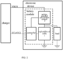
- FIG. 2 is a block diagram of a battery module according to an exemplary embodiment.
- the battery module includes: a plurality of cells 1, a series-parallel conversion circuit 2 and a controller 3.
- the series-parallel conversion circuit 2 is respectively coupled to the controller 3 and the plurality of cells 1.
- the controller 3 is configured to control the series-parallel conversion circuit 2 to convert a connection mode of cells in the plurality of cells 1 when the battery module is to be charged, such that the plurality of cells 1 form a charging architecture state with a charging current greater than a preset current value, the charging architecture state including at least one of: at least two cells coupled in series, at least two cells coupled in parallel, a combination of first cells coupled in series and second cells coupled in parallel, and a single cell.
- the controller 3 may be arranged inside the battery module, that is, the battery module may be produced as an independent product.
- the controller 3 may be implemented by a processor or a power management chip of an electronic device where the battery module is in, which is not limited here.
- the following embodiments of the present invention are described by taking an example of arranging the controller 3 inside the battery module.
- the battery module may directly communicate with an external charger that charges the battery module and determine whether to charge the battery module, thereby improving the charging efficiency.
- dependence of the battery module on the processor or the power management chip of the electronic device may be reduced, and working efficiency of the processor or the power management chip may be improved.
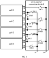
- FIG. 3 is a circuit diagram of the series-parallel conversion circuit 2 ( FIG. 2 ) according to an exemplary embodiment.
- the series-parallel conversion circuit 2 includes a plurality of switching devices (e.g., SW1 to SW11). Each of the plurality of switching devices is coupled to a positive electrode (indicated by "+”) or a negative electrode (indicated by "-") of one cell. As illustrated in FIG.
- a switching device SW8 is coupled to a positive electrode of a cell 1
- switching devices SW5 and SW9 are coupled to a positive electrode of a cell 2
- switching devices SW6 and SW10 are coupled to a positive electrode of a cell 3
- switching devices SW7 and SW11 are coupled to a positive electrode of a cell 4
- switching devices SW8, SW9, SW10 and SW11 are coupled to a power input end P+.
- the switching device SW5 is also coupled to a negative electrode of the cell 1
- the switching device SW6 is also coupled to a negative electrode of the cell 2
- SW7 is also coupled to a negative electrode of the cell 3.
- the positive electrode is coupled to a power input end of the battery module or a negative electrode of an upper-level cell based on a control signal of the controller.
- the switching device SW5 may couple the positive electrode of the cell 2 to the negative electrode of the cell 1
- the cell SW9 may couple the positive electrode of the cell 2 to the power input end P+.
- the negative electrode is coupled to the power output end of the battery module based on the control signal of the controller.
- the switching device SW1 may couple the negative electrode of the cell 1 to a power output end P-.
- the upper-level cell may be a cell that is located between a current-level cell and the power input end P+ and is closest to the current-level cell in a series charging architecture state of the plurality of cells.
- the cell 1 is an upper-level cell of the cell 2
- the cell 2 is an upper-level cell of the cell 3
- the cell 3 is an upper-level cell of the cell 4. It should be noted that since the cell 1 is directly coupled to the power input end P+, the cell 1 does not have an upper-level cell.
- the series-parallel conversion circuit 2 may include: the switching device SW1, the switching device SW2, the switching device SW3, the switching device SW4, the switching device SW5, the switching device SW6, the switching device SW7, the switching device SW8, and the switching device SW9, the switching device SW10 and the switching device SW11.
- the switching device SW1 is arranged between the negative electrode of the cell 1 and the power output end P-
- the switching device SW2 is arranged between the negative electrode of the cell 2 and the power output end P-
- the switching device SW3 is arranged between the negative electrode of the cell 3 and the power output end P-
- the switching device SW4 is arranged between the negative electrode of the cell 4 and the power output end P-.
- the switching device SW8 is arranged between the positive electrode of the cell 1 and the power input end P+.
- the switching device SW5 is arranged between the positive electrode of the cell 2 and the negative electrode of the cell 1
- the switching device SW6 is arranged between the positive electrode of the cell 3 and the negative electrode of the cell 2
- the switching device SW7 is arranged between the positive electrode of the cell 4 and the negative electrode of the cell 3.
- the switching device SW9 is arranged between the positive electrode of the cell 2 and the power input end P+
- the switching device SW10 is arranged between the positive electrode of the cell 3 and the power input end P+
- the switching device SW11 is coupled in series between the positive electrode of the cell 2 and the power input end P+.
- control ends of the above-mentioned switching devices SW1 to SW11 are all coupled to the controller 3, so that the control signal sent by the controller 3 may be received, and an ON state or an OFF state may be realized based on the control signal.
- the switching devices SW1 to SW11 may be implemented by field effect transistors.
- the switching devices SW1 to SW11 may also be implemented by a single-pole double-throw switch.
- the switching devices SW5 and SW9 may be implemented by one single-pole double-throw switch.
- SW6 and SW10 as well as SW7 and SW11 may be implemented by one single-pole double-throw switch, respectively.
- the series-parallel conversion circuit 2 is configured to adjust the cells 1 to 4 to one of the following charging architecture states: at least two cells coupled in series, at least two cells coupled in parallel, a combination of first cells coupled in series and second cells coupled in parallel, and a single cell, states of the switching devices SW5, SW6 and SW7 are different from states of other switching devices. For example, when the switching devices SW5, SW6 and SW7 are in the ON state, positive electrodes of current-level cells will be coupled to negative electrodes of upper-level cells, and when the switching devices SW5, SW6 and SW7 are in the OFF state, the connection between the positive electrodes of the current-level cells and the negative electrodes of the upper-level cells will be disconnected. Referring to FIG.
- an ON state of SW5 refers to a connection to the left end of the switching device SW1. In this manner, the positive electrode of the cell 2 is coupled to the negative electrode of the cell 1.
- the OFF state of the switching device SW5 refers to disconnecting a connection between the positive electrode of the cell 2 and the negative electrode of the cell 1.
- the controller 3 may directly communicate with the charger.
- the charger has different protocol types
- the battery module further includes a protocol conversion chip.
- the protocol conversion chip is arranged between the controller 3 and the charger and is configured for a charging protocol conversion between the controller and the charger.
- the controller 3 may communicate with the external charger to determine a charging parameter that the charger may provide. In an embodiment, the controller 3 may not require the charger to determine the charging parameter that it may provide, that is, the controller determines that the charger may provide any charging parameter required by the battery module by default.
- the charging voltage is four times of the cell voltage. And the four cells are charged in series.
- the controller 3 obtains current charging parameters of the battery module, such as electric quantity, a relative voltage or an absolute voltage, and preset parameter thresholds of the charging parameters.
- the charging parameter as the electric quantity
- the controller 3 may determine whether the battery module is to be charged based on a current electric quantity and an electric quantity threshold.
- the electric quantity threshold may be set to several groups, such as 80%, 60%, 45%, and 30% and below.
- the battery module is to be charged.
- the current electric quantity of the battery module is greater than 80%, the battery module may not to be charged.
- the battery module may be charged.
- the battery module may not to be charged when the electric quantity is equal to 100%.
- a person skilled in the art may make settings according to specific scenes.
- the charging parameter may also be a charging level.
- the controller determines the charging level based on the electric quantity of the battery and the voltage, as illustrated in Table 1.
- Table 1 Charging level 1 2 3 4 Output voltage 0.5-5 5-10 10-15 15-20 Output current 0.1-3 1.5-3 1.5-3 3-6
- the controller 3 generates a charging request when determining that the battery module is to be charged.
- the charging request includes charging parameters required by the battery module.
- the method to calculate the charging power may be referred to related technologies, and is not limited here.
- the controller 3 may send the charging request to the charger.
- the charger obtains the charging parameter in the charging request, and determines whether the charging parameter may be provided to obtain a determination result that the charging parameter may be or may not be provided.
- the charger feeds back the determination result to the controller 3.
- the charger may also feeds back a charging parameter that may be provided. For example, the charger may not provide a charging power of 85W, but may provide a charging power of 50W.
- the controller 3 may control the series-parallel conversion circuit 2 to convert to a charging architecture state corresponding to the charging parameter, and send a preset identifier to the charger after the series-parallel conversion circuit 2 is successfully converted to the charging architecture state.
- the preset identifier is configured to instruct the charger to charge the battery module with the charging parameter. Take the above charging power being provided by the charger as an example.
- the charger charges the battery module based on the charging power of 85W.
- the charging voltage is twice the cell voltage.
- every two cells in the four cells are coupled in series and then charged in parallel.
- the charger may only provide a charging voltage that is twice the cell voltage.
- the controller 3 obtains the current charging parameter of the battery module and determines whether the battery module is to be charged. The controller 3 generates the charging request when determining that the battery module is to be charged. The charging request includes the charging parameter required by the battery module.
- the controller 3 may send the charging request to the charger.
- the charger obtains the charging parameter in the charging request, and determines whether the above charging parameter may be satisfied to obtain a determination result that the above charging parameter may be or may not be satisfied.
- the charger feeds back the determination result to the controller 3.
- a charging parameter that the charger may satisfy may be fed back to the controller 3.
- the controller 3 may send the control signal to the series-parallel conversion circuit 2 based on the charging parameter that may be satisfied.
- the charger charges the battery module based on the charging power of 45W.
- the charging voltage is equal to the cell voltage, and the four cells are charged in parallel.
- the charger may only provide a charging voltage that is the same as the cell voltage.
- the controller 3 obtains the current charging parameter of the battery module and determines whether the battery module is to be charged. The controller 3 generates the charging request when determining that the battery module is to be charged. The charging request includes the charging parameter required by the battery module.
- the controller 3 may send the charging request to the charger.
- the charger obtains the charging parameter in the charging request, and determines whether the charging parameter may be satisfied to obtain a determination result that the above charging parameter may be or may not be satisfied.
- the charger feeds back the determination result to the controller 3.
- a charging parameter that the charger may satisfy may be fed back to the controller 3.
- the controller 3 sends the control signal to the series-parallel conversion circuit 2, based on the charging parameter that may be satisfied.
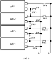
- Each switching device in the series-parallel conversion circuit 2 is switched to the ON state or OFF state based on the control signal, so that the cells 1 to 4 are charged in parallel to obtain the circuit as illustrated in FIG. 6 . Assuming that the charging voltage of each cell is 4.5V, the output voltage of the charger is 4.5V, and the charging power is 22.5W.
- the charger charges the battery module based on the charging power of 22.5W.
- the controller 3 may also control any set of the cells 1 and 2, the cells 2 and 3, the cells 3 and 4, and any one of cells 1 to 4 for charging.
- the charging voltage is no longer limited to four times, two times and one times of the cell voltage. The combinations also falls into the scope of the present invention.
- the charger charges the battery module.
- the controller 3 may detect the charging parameter of the battery module in real time.
- the controller 3 regenerates the charging request sent to the charger based on the charging parameter, so that the charger adjusts the charging power in the current charging architecture state. For example, when the voltage of each cell in the battery module reaches 4.6V, constant voltage (CV) charging may be adopted. In this manner, the charging current is adjusted to reduce the charging power until the charging is completed.
- CV constant voltage
- the controller 3 may also adjust the charging architecture state of the plurality of cells. Referring to FIG. 9 , at block 91, the controller 3 may obtain a charging current of the plurality of cells. For example, the controller 3 may communicate with a voltammeter in the battery module to obtain the charging current.
- the controller 3 compares the charging current with a preset current value (for example, 2.5A). When the charging current is less than the preset current value, the controller 3 may couple two (or more) cells in series, and then a plurality of series branches are coupled in parallel, thereby obtaining a series-parallel charging architecture. In this manner, when the charging current does not exceed the maximum current of the charging cable, the voltage of the cells is balanced by parallel charging, so that the plurality of cells may be in the same state of use, trying to achieve an effect of synchronous charging, and improving the charging efficiency.
- a preset current value for example, 2.5A
- the controller 3 may couple two cells in series to form one series branch, so that two series branches may be coupled in parallel to realize a current of 5A of the charging cable.
- the controller 3 may switch the charging architecture state 1 to the charging architecture state 2. In the charging architecture state 2, as the cell voltage increases, the charging current will continue to decrease.
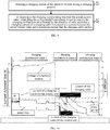
- the controller 3 may change the charging architecture state 2 to the charging architecture state 3. Based on the above charging process, the charging curve illustrated in FIG. 10 may be obtained. Compare the current of the charging cable in the related art with the current of the charging cable according to the embodiment, for the charging architecture state 2 and charging architecture state 3, the current of the charging cable according to the embodiment is between 2.5A and 5A, while the current of the charging cable in the related art continues to decrease. In this manner, the charging voltage of each cell is balanced while the balance of the charging power of each cell is maintained, so that the charging efficiency is increased.
- the charging architecture state of the plurality of cells is adjusted, such that the charging current is greater than the preset current value and less than the maximum current of the charging cable. That is, the battery module may be charged with a high voltage and a large current without a voltage conversion device, helping to increase the charging efficiency of the battery module.
- the series-parallel conversion circuit according to embodiments of the present invention does not participate in voltage conversion and does not cause heat loss, which is beneficial to improving the charging efficiency of the battery module.
- the present invention provides a charging control method, which is applicable to a battery module including a plurality of cells.
- the method includes: determining whether the battery module is to be charged; and in response to that the battery module is to be charged, converting a connection mode of cells in the plurality of cells, such that the plurality of cells form a charging architecture state with a charging current greater than a preset current value.
- the charging architecture state includes at least one of: at least two cells coupled in series, at least two cells coupled in parallel, a combination of first cells coupled in series and second cells coupled in parallel, and a single cell.
- the method before converting the connection mode of the cells in the plurality of cells, includes: determining a charging parameter provided by an external charger; and converting the connection mode of the cells in the plurality of cells, such that the plurality of cells form a charging architecture state matching the charging parameter provided by the external charger.
- the method before controlling the series-parallel conversion circuit to convert the connection mode of the cells in the plurality of cells, the method includes: in response to that the battery module is to be charged, generating a charging request, wherein the charging request includes an charging power required by the battery module; sending the charging request to an external charger, such that the external charger determines whether the external charger can satisfy the required charging power and returns a determination result, wherein the determination result includes a target charging power that the external charger may provide, and the target charging power is less than or equal to the required charging power; and after the determination result is received, converting the connection mode of cells in the plurality of cells, such that the plurality of cells form a charging architecture state matching the target charging power, and an initial charging current in the charging architecture state being a maximum current that a charging cable may carry.
- generating the charging request includes: obtaining a current voltage of the plurality of cells and the maximum current that the charging cable may carry; obtaining the charging power required by the battery module based on the current voltage and the maximum current; and generating the charging request based on the obtained charging power.
- the method includes sending a preset identifier to an external charger after the plurality of cells are converted into the charging architecture state.
- the preset identifier is configured to instruct the external charger to charge the battery module at a target charging power.
- the method includes: obtaining a charging current of the plurality of cells during a charging process; and in response to the charging current being less than the preset current value, converting the charging architecture state formed by the plurality of cells, such that a charging current of a charging cable is restored to a current between the preset current value and a maximum current that the charging cable may carry.
- determining whether the battery module is to be charged includes: obtaining at least one current charging parameter of the battery module and at least one preset parameter threshold of the at least one current charging parameter; and determining whether the battery module is to be charged, based on the at least one preset parameter threshold and the at least one current charging parameter.
- the method according to embodiments of the present invention corresponds to embodiments of the charging device.
- the specific content of the method may be referred to the content of embodiments of the charging device, and thus will not be repeated here.
- FIG. 11 is a block diagram of a charging control apparatus according to an exemplary embodiment.
- FIG. 11 illustrates a charging control apparatus, which is applicable to a battery module including a plurality of cells, a series-parallel conversion circuit, and a controller.
- the apparatus includes a charging determination module 111 and an architecture conversion module 112.
- the charging determination module 111 is configured to determine whether the battery module is to be charged.
- the architecture conversion module 112 is configured to, in response to that the battery module is to be charged, control the series-parallel conversion circuit to convert a connection mode of cells in the plurality of cells, such that the plurality of cells form a charging architecture state with a charging current greater than a preset current value.
- the charging architecture state includes at least one of: at least two cells coupled in series, at least two cells coupled in parallel, a combination of first cells coupled in series and second cells coupled in parallel, and a single cell.
- the apparatus includes a request generation module 121, a request sending module 122, and a trigger module 123.
- the request generation module 121 is configured to, in response to that the battery module is to be charged, generate a charging request.
- the charging request includes an expected charging power required by the battery module.
- the request sending module 122 is configured to send the charging request to an external charger, such that the external charger determines whether the external charger can satisfy the required charging power and returns a determination result.
- the determination result includes a target charging power that the external charger may provide, and the target charging power is less than or equal to the required charging power.
- the trigger module 123 is configured to, after the determination result is received, trigger the architecture conversion module to convert a charging architecture, such that the plurality of cells form a charging architecture state matching the target charging power.
- An initial charging current in the charging architecture state is a maximum current that a charging cable may carry.
- the request generation module 121 ( FIG. 12 ) includes a voltage and current obtaining unit 131, an expected power obtaining unit 132, and a charging request generation unit 133.
- the voltage and current obtaining unit 131 is configured to obtain a current voltage of the plurality of cells and the maximum current that the charging cable may carry.
- the expected power obtaining unit 132 is configured to obtain the charging power required by the battery module based on the current voltage and the maximum current.
- the charging request generation unit 133 is configured to generate the charging request based on the obtained charging power.
- the apparatus includes a preset identifier sending module.
- the preset identifier sending module is configured to send a preset identifier to an external charger after the plurality of cells are converted into the charging architecture state.
- the preset identifier is configured to instruct the external charger to charge the battery module at a target charging power.
- the apparatus includes a charging current obtaining module 141 and an architecture conversion module 142.
- the charging current obtaining module 141 is configured to obtain a charging current of the plurality of cells during a charging process.
- the architecture conversion module 142 is configured to, in response to the charging current being less than the preset current value, control the series-parallel conversion circuit to convert the charging architecture state formed by the plurality of cells, such that a charging current of a charging cable is restored to a current between the preset current value and a maximum current that the charging cable may carry.
- the apparatus according to the present invention corresponds to the method embodiments as described above.
- the specific content of the apparatus may be referred to the content of the method embodiments, and thus will not be repeated here.
- FIG. 15 is a block diagram of an electronic device 1500 according to an exemplary embodiment.
- the electronic device 1500 may be a smartphone, a computer, a digital broadcast terminal, a tablet device, a medical device, an exercise device, a personal digital assistant, and so on.
- the electronic device 1500 may include one or more of the following components: a processing component 1502, a memory 1504, a power component 1506, a multimedia component 1508, an audio component 1510, an input/output (I/O) interface 1512, a sensor component 1514, a communication component 1516, and an image acquisition component 1518.
- a processing component 1502 a memory 1504
- a power component 1506 a multimedia component 1508, an audio component 1510, an input/output (I/O) interface 1512, a sensor component 1514, a communication component 1516, and an image acquisition component 1518.
- I/O input/output
- the processing component 1502 normally controls the overall operation (such as operations associated with displaying, telephone calls, data communications, camera operations and recording operations) of the electronic device 1500.
- the processing component 1502 may include one or a plurality of processors 1520 to execute instructions so as to perform all or part of the steps of the above described method.
- the processing component 1502 may include one or a plurality of units to facilitate interactions between the processing component 1502 and other components.
- the processing component 1502 may include a multimedia unit to facilitate interactions between the multimedia component 1508 and the processing component 1502.
- the memory 1504 is configured to store various types of data to support operations at the electronic device 1500. Examples of such data include computer programs for any application or method operated on the electronic device 1500, contact data, phone book data, messages, images, videos and the like.
- the memory 1504 may be realized by any type of volatile or non-volatile storage devices, or a combination thereof, such as a static random access memory (SRAM), an electrically erasable programmable read only memory (EEPROM), an erasable programmable read only memory (EPROM), a programmable read only memory (PROM), a read only memory (ROM), a magnetic memory, a flash memory, a disk or an optical disk.
- SRAM static random access memory
- EEPROM electrically erasable programmable read only memory
- EPROM erasable programmable read only memory
- PROM programmable read only memory
- ROM read only memory
- magnetic memory a magnetic memory
- flash memory a flash memory
- disk or an optical disk an optical disk.
- the power component 1506 provides power to various components of the electronic device 1500.
- the power component 1506 may include a power management system, one or a plurality of power sources and other components associated with power generation, management, and distribution of the electronic device 1500.
- the power component 1506 may include a power chip.
- the controller may communicate with the power chip to control the power chip to turn on or off the switching device, so that the battery supplies power or does not supply power to a main board circuit.
- the power component 1506 includes the battery module illustrated in FIGS. 2-6 .
- the multimedia component 1508 includes a screen that provides an output interface between the electronic device 1500 and a target object.
- the screen may include a liquid crystal display (LCD) and a touch panel (TP). If the screen includes a touch panel, the screen may be implemented as a touch screen to receive input signals from the user.
- the touch panel includes one or a plurality of touch sensors to sense touches, slides, and gestures on the touch panel. The touch sensor may sense not only the boundary of the touches or sliding actions, but also the duration and pressure related to the touches or sliding operations.
- the audio component 1510 is configured to output and/or input an audio signal.
- the audio component 1510 includes a microphone (MIC) that is configured to receive an external audio signal when the electronic device 1500 is in an operation mode such as a call mode, a recording mode, and a voice recognition mode.
- the received audio signal may be further stored in the memory 1504 or transmitted via the communication component 1516.
- the audio component 1510 further includes a speaker for outputting audio signals.
- the I/O interface 1512 provides an interface between the processing component 1502 and a peripheral interface unit.
- the peripheral interface unit may be a keyboard, a click wheel, a button and so on.
- the sensor assembly 1514 includes one or more sensors for providing the electronic device 1500 with various aspects of status assessments.
- the sensor component 1514 may detect an ON/OFF state of the electronic device 1500 and a relative positioning of the components.
- the components may be a display and a keypad of the electronic device 1500.
- the sensor component 1514 may also detect a change in position of the electronic device 1500 or a component of the electronic device 1500, the presence or absence of contact of the target object with the electronic device 1500, the orientation or acceleration/deceleration of the electronic device 1500 and a temperature change of the electronic device 1500.
- the communication component 1516 is configured to facilitate wired or wireless communication between the electronic device 1500 and other devices.
- the electronic device 1500 may access a wireless network based on a communication standard such as Wi-Fi, 2G, 3G, 4G/LTE or 5G or a combination thereof.
- the communication component 1516 receives broadcast signals or broadcast-associated information from an external broadcast management system via a broadcast channel.
- the communication component 1516 further includes a near field communication (NFC) module to facilitate short range communication.
- the NFC module can be implemented based on radio frequency identification (RFID) technology, infrared data association (IrDA) technology, ultra-wideband (UWB) technology, Bluetooth (BT) technology and other technologies.
- RFID radio frequency identification
- IrDA infrared data association
- UWB ultra-wideband
- Bluetooth Bluetooth
- the electronic device 1500 may be implemented by one or a plurality of application specific integrated circuits (ASICs), digital signal processors (DSPs), digital signal processing devices (DSPDs), programmable logic devices (PLDs), field programmable gate arrays (FPGA), controllers, microcontrollers, microprocessors, or other electronic components.
- ASICs application specific integrated circuits
- DSPs digital signal processors
- DSPDs digital signal processing devices
- PLDs programmable logic devices
- FPGA field programmable gate arrays
- controllers microcontrollers, microprocessors, or other electronic components.
- a non-transitory readable storage medium including executable computer programs, such as a memory 1504 including instructions.
- the executable computer programs are executable by the processor.
- the readable storage medium may be a ROM, a random access memory (RAM), a CD-ROM, a magnetic tape, a floppy disk, an optical data storage device, etc.
Landscapes
- Engineering & Computer Science (AREA)
- Power Engineering (AREA)
- Charge And Discharge Circuits For Batteries Or The Like (AREA)
- Secondary Cells (AREA)
Abstract
Description
- The present invention relates to the field of charging technologies, and more particularly, to a battery module, a charging control method, an electronic device, and a storage medium.
- Electronic devices in the related prior art adopt the following charging architecture. As illustrated in
FIG. 1 , the architecture usually includes acharger 01 and amobile phone 03. Themobile phone 03 includes a charging conversion device (such as acharging circuit 021 and a charging circuit 022) and a battery module system. In order to prevent the charging current from exceeding a maximum current of the charging cable, in the related art, an output voltage of thecharger 01 is generally increased, and a voltage conversion is performed through thecharging circuit 021 and thecharging circuit 022. Normally, the output voltage of thecharging circuit 021 and thecharging circuit 022 is half of the output voltage of thecharger 01, that is, the battery module is charged with a high voltage and a low current. However, in the above-mentioned charging architecture, the charging conversion device may generate heat loss during a voltage conversion process, which heats up a temperature of the mobile phone, reduces charging efficiency, prolongs charging time, and affects charging experience of users. - The present invention provides a battery module, a charging control method, an electronic device, and a storage medium to solve deficiencies in the related art.
- According to a first aspect of the present invention, a battery module is provided. The battery module includes a plurality of cells, a series-parallel conversion circuit and a controller. The controller is coupled to the series-parallel conversion circuit and is configured to control the series-parallel conversion circuit to convert a connection mode of cells in the plurality of cells when the battery module is to be charged, such that the plurality of cells form a charging architecture state with a charging current greater than a preset current value. The charging architecture state includes at least one of: at least two cells coupled in series, at least two cells coupled in parallel, a combination of first cells coupled in series and second cells coupled in parallel, and a single cell.
- Optionally, the controller is integrated into the battery module, or the controller is implemented by a processor of an electronic device provided with the battery module, or the controller is implemented by a power management module of the electronic device.
- Preferably, the series-parallel conversion circuit includes a plurality of switching devices, and each switching device in the plurality of switching devices is coupled to a positive electrode or a negative electrode of one cell. In response to being coupled to the positive electrode of one cell, the switching device is configured to connect the positive electrode to a power input end of the battery module or a negative electrode of an upper-level cell based on a control signal of the controller. In response to being coupled to the negative electrode of one cell, the switching device is configured to connect the negative electrode to a power output end of the battery module based on the control signal of the controller.
- Optionally, the battery module includes a protocol conversion chip coupled to the controller and configured for a charging protocol conversion between the controller and an external charger.
- Preferably, the controller is configured to obtain a charging current of the plurality of cells during a charging process, and in response to the charging current being less than the preset current value, to control the series-parallel conversion circuit to convert the charging architecture state formed by the plurality of cells, such that a charging current of a charging cable is restored to a current between the preset current value and a maximum current that the charging cable may carry.
- According to a second aspect of the present invention, a charging control method for a battery module is provided. The battery module including a plurality of cells. The method includes: determining whether the battery module is to be charged; and in response to that the battery module is to be charged, converting a connection mode of cells in the plurality of cells, such that the plurality of cells form a charging architecture state with a charging current greater than a preset current value. The charging architecture state includes at least one of: at least two cells coupled in series, at least two cells coupled in parallel, a combination of first cells coupled in series and second cells coupled in parallel, and a single cell.
- Optionally, before converting the connection mode of the cells in the plurality of cells, the method includes: determining a charging parameter provided by an external charger; and converting the connection mode of the cells in the plurality of cells, such that the plurality of cells form a charging architecture state matching the charging parameter provided by the external charger.
- Preferably, before controlling the series-parallel conversion circuit to convert the connection mode of the cells in the plurality of cells, the method includes: in response to that the battery module is to be charged, generating a charging request, wherein the charging request includes an charging power required by the battery module; sending the charging request to an external charger, such that the external charger determines whether the external charger satisfies the required charging power and returns a determination result, wherein the determination result includes a target charging power that the external charger may provide, and the target charging power is less than or equal to the expected charging power; and after the determination result is received, converting the connection mode of the cells in the plurality of cells, such that the plurality of cells form a charging architecture state matching the target charging power, and an initial charging current in the charging architecture state being a maximum current that a charging cable may carry.
- Optionally, generating the charging request includes: obtaining a current voltage of the plurality of cells and the maximum current that the charging cable may carry; obtaining the charging power required by the battery module based on the current voltage and the maximum current; and generating the charging request based on the obtained charging power.
- Preferably, the method includes sending a preset identifier to an external charger after the plurality of cells are converted into the charging architecture state. The preset identifier is configured to instruct the external charger to charge the battery module at a target charging power.
- Optionally, the method includes: obtaining a charging current of the plurality of cells during a charging process; and in response to the charging current being less than the preset current value, converting the charging architecture state formed by the plurality of cells, such that a charging current of a charging cable is restored to a current between the preset current value and a maximum current that the charging cable may carry.
- Preferably, determining whether the battery module is to be charged includes: obtaining at least one current charging parameter of the battery module and at least one preset parameter threshold of the at least one current charging parameter; and determining whether the battery module is to be charged, based on the at least one preset parameter threshold and the at least one current charging parameter.
- According to a third aspect of the present invention, an electronic device is provided. The electronic device includes a battery module, a processor and a storage device configured to store a computer program executable by the processor. The processor is configured to execute the computer program in the storage device to implement steps of the above method.
- According to a fourth aspect of the present invention, a readable storage medium having an executable computer program stored thereon is provided. When the computer program is executed, steps of the method are implemented.
- The technical solution according to embodiments of the present invention includes the following beneficial effects.
- It may be seen from the above embodiments that the controller according to the present invention may determine whether the battery module is to be charged. In response to that the battery module is to be charged, the series-parallel conversion circuit is controlled to convert the connection mode of cells in the plurality of cells, such that the plurality of cells form the charging architecture state with the charging current greater than the preset current value. The charging architecture state includes at least one of: at least two cells coupled in series, at least two cells coupled in parallel, a combination of first cells coupled in series and second cells coupled in parallel, and a single cell. In this manner, according to the present invention, the charging architecture state of the plurality of cells is adjusted, such that the charging current is greater than the preset current value and less than the maximum current of the charging cable. That is, the battery module may be charged with a high voltage and a large current without a voltage conversion device, helping to increase charging efficiency of the battery module. In addition, the series-parallel conversion circuit according to embodiments of the present invention does not participate in voltage conversion and does not cause heat loss, which is beneficial to improving the charging efficiency of the battery module.
- It should be understood that the above general description and the following detailed description are only exemplary and explanatory, and cannot limit the present invention.
- The accompanying drawings, which are incorporated in and constitute a part of this specification, illustrate embodiments consistent with the present invention and, together with the description, serve to explain the principles of the present invention.
-
FIG. 1 is a block diagram of an electronic device in related art. -
FIG. 2 is a block diagram of a battery module according to an exemplary embodiment. -
FIG. 3 is a circuit diagram of a series-parallel conversion circuit according to an exemplary embodiment. -
FIGS. 4-6 are circuit diagrams of a charging architecture of a series-parallel conversion circuit according to an exemplary embodiment. -
FIGS. 7-9 are flowcharts of a charging control method according to an exemplary embodiment. -
FIG. 10 is a schematic diagram of a charging curve according to an exemplary embodiment. -
FIGS. 11-14 are block diagrams of a charging control apparatus according to an exemplary embodiment. -
FIG. 15 is a block diagram of an electronic device according to an exemplary embodiment. - Reference will now be made in detail to exemplary embodiments, examples of which are illustrated in the accompanying drawings. The following description refers to the accompanying drawings in which the same numbers in different drawings represent the same or similar elements unless otherwise represented. The implementations set forth in the following description of exemplary embodiments do not represent all implementations consistent with the present invention. Instead, they are merely examples of apparatuses and methods consistent with aspects related to the present invention as recited in the appended claims.
- Electronic devices in related art adopt the following charging architecture. As illustrated in
FIG. 1 , the architecture usually includes acharger 01 and amobile phone 03. Themobile phone 03 includes a charging conversion device (FIG. 1 includes acharging circuit 021 and a charging circuit 022) and a battery module system. In order to prevent the charging current from exceeding a maximum current of a charging cable, in the related art, an output voltage of thecharger 01 is generally increased, and a voltage conversion is performed through thecharging circuit 021 and thecharging circuit 022. Normally, the output voltage of thecharging circuit 021 and thecharging circuit 022 is half of the output voltage of thecharger 01, that is, the battery module is charged with a high voltage and a low current. However, in the above-mentioned charging architecture, the charging conversion device generates heat loss during the voltage conversion process, which heats up a temperature of the mobile phone, reduces charging efficiency, prolongs charging time, and affects charging experience of users. - To solve the above technical problems, embodiments of the present invention provide a battery module. A series-parallel conversion circuit is arranged in the battery module, and the series-parallel conversion circuit is configured to adjust a charging architecture state of a plurality of cells in the battery module, such that a charging current is adjusted to be greater than a preset current value and less than a maximum current of a charging cable. Consequently, an effect of using a high voltage and large current to charge the battery module is achieved, which is beneficial to improving the charging efficiency of the battery module. In addition, the series-parallel conversion circuit according to the present invention neither participates in voltage conversion nor causes heat loss, which is also helpful for improving the charging efficiency of the battery module.
-
FIG. 2 is a block diagram of a battery module according to an exemplary embodiment. Referring toFIG. 2 , the battery module includes: a plurality ofcells 1, a series-parallel conversion circuit 2 and acontroller 3. The series-parallel conversion circuit 2 is respectively coupled to thecontroller 3 and the plurality ofcells 1. Thecontroller 3 is configured to control the series-parallel conversion circuit 2 to convert a connection mode of cells in the plurality ofcells 1 when the battery module is to be charged, such that the plurality ofcells 1 form a charging architecture state with a charging current greater than a preset current value, the charging architecture state including at least one of: at least two cells coupled in series, at least two cells coupled in parallel, a combination of first cells coupled in series and second cells coupled in parallel, and a single cell. - It should be noted that the
controller 3 according to the embodiment may be arranged inside the battery module, that is, the battery module may be produced as an independent product. In an embodiment, thecontroller 3 may be implemented by a processor or a power management chip of an electronic device where the battery module is in, which is not limited here. The following embodiments of the present invention are described by taking an example of arranging thecontroller 3 inside the battery module. In this case, the battery module may directly communicate with an external charger that charges the battery module and determine whether to charge the battery module, thereby improving the charging efficiency. In addition, dependence of the battery module on the processor or the power management chip of the electronic device may be reduced, and working efficiency of the processor or the power management chip may be improved. -
FIG. 3 is a circuit diagram of the series-parallel conversion circuit 2 (FIG. 2 ) according to an exemplary embodiment. In the embodiment, the series-parallel conversion circuit 2 includes a plurality of switching devices (e.g., SW1 to SW11). Each of the plurality of switching devices is coupled to a positive electrode (indicated by "+") or a negative electrode (indicated by "-") of one cell. As illustrated inFIG. 3 , a switching device SW8 is coupled to a positive electrode of acell 1, switching devices SW5 and SW9 are coupled to a positive electrode of acell 2, switching devices SW6 and SW10 are coupled to a positive electrode of acell 3, switching devices SW7 and SW11 are coupled to a positive electrode of acell 4, and switching devices SW8, SW9, SW10 and SW11 are coupled to a power input end P+. The switching device SW5 is also coupled to a negative electrode of thecell 1, the switching device SW6 is also coupled to a negative electrode of thecell 2, and SW7 is also coupled to a negative electrode of thecell 3. In this manner, when a switching device is coupled to a positive electrode of a cell, the positive electrode is coupled to a power input end of the battery module or a negative electrode of an upper-level cell based on a control signal of the controller. For example, the switching device SW5 may couple the positive electrode of thecell 2 to the negative electrode of thecell 1, and the cell SW9 may couple the positive electrode of thecell 2 to the power input end P+. - When the switching device is coupled to the negative electrode of the cell, the negative electrode is coupled to the power output end of the battery module based on the control signal of the controller. For example, the switching device SW1 may couple the negative electrode of the
cell 1 to a power output end P-. - The upper-level cell may be a cell that is located between a current-level cell and the power input end P+ and is closest to the current-level cell in a series charging architecture state of the plurality of cells. Referring to
FIG. 3 , when thecells 1 to 4 are charged in the series charging architecture state, thecell 1 is an upper-level cell of thecell 2, thecell 2 is an upper-level cell of thecell 3, and thecell 3 is an upper-level cell of thecell 4. It should be noted that since thecell 1 is directly coupled to the power input end P+, thecell 1 does not have an upper-level cell. - In an embodiment, a number of the plurality of cells is four. With continued reference to
FIG. 3 , the series-parallel conversion circuit 2 may include: the switching device SW1, the switching device SW2, the switching device SW3, the switching device SW4, the switching device SW5, the switching device SW6, the switching device SW7, the switching device SW8, and the switching device SW9, the switching device SW10 and the switching device SW11. The switching device SW1 is arranged between the negative electrode of thecell 1 and the power output end P-, the switching device SW2 is arranged between the negative electrode of thecell 2 and the power output end P-, the switching device SW3 is arranged between the negative electrode of thecell 3 and the power output end P-, and the switching device SW4 is arranged between the negative electrode of thecell 4 and the power output end P-. The switching device SW8 is arranged between the positive electrode of thecell 1 and the power input end P+. The switching device SW5 is arranged between the positive electrode of thecell 2 and the negative electrode of thecell 1, the switching device SW6 is arranged between the positive electrode of thecell 3 and the negative electrode of thecell 2, and the switching device SW7 is arranged between the positive electrode of thecell 4 and the negative electrode of thecell 3. The switching device SW9 is arranged between the positive electrode of thecell 2 and the power input end P+, the switching device SW10 is arranged between the positive electrode of thecell 3 and the power input end P+, and the switching device SW11 is coupled in series between the positive electrode of thecell 2 and the power input end P+. - It should be noted that control ends of the above-mentioned switching devices SW1 to SW11 are all coupled to the
controller 3, so that the control signal sent by thecontroller 3 may be received, and an ON state or an OFF state may be realized based on the control signal. - In an embodiment, the switching devices SW1 to SW11 may be implemented by field effect transistors. The switching devices SW1 to SW11 may also be implemented by a single-pole double-throw switch. In an embodiment, the switching devices SW5 and SW9 may be implemented by one single-pole double-throw switch. Similarly, SW6 and SW10 as well as SW7 and SW11 may be implemented by one single-pole double-throw switch, respectively.
- In an embodiment, the series-
parallel conversion circuit 2 is configured to adjust thecells 1 to 4 to one of the following charging architecture states: at least two cells coupled in series, at least two cells coupled in parallel, a combination of first cells coupled in series and second cells coupled in parallel, and a single cell, states of the switching devices SW5, SW6 and SW7 are different from states of other switching devices. For example, when the switching devices SW5, SW6 and SW7 are in the ON state, positive electrodes of current-level cells will be coupled to negative electrodes of upper-level cells, and when the switching devices SW5, SW6 and SW7 are in the OFF state, the connection between the positive electrodes of the current-level cells and the negative electrodes of the upper-level cells will be disconnected. Referring toFIG. 3 , taking the switching device SW5 as an example, an ON state of SW5 refers to a connection to the left end of the switching device SW1. In this manner, the positive electrode of thecell 2 is coupled to the negative electrode of thecell 1. The OFF state of the switching device SW5 refers to disconnecting a connection between the positive electrode of thecell 2 and the negative electrode of thecell 1. - The
controller 3 may directly communicate with the charger. In an embodiment, the charger has different protocol types, and the battery module further includes a protocol conversion chip. The protocol conversion chip is arranged between thecontroller 3 and the charger and is configured for a charging protocol conversion between the controller and the charger. - In an embodiment, the
controller 3 may communicate with the external charger to determine a charging parameter that the charger may provide. In an embodiment, thecontroller 3 may not require the charger to determine the charging parameter that it may provide, that is, the controller determines that the charger may provide any charging parameter required by the battery module by default. - In the following, the working process of the battery modules in different charging architecture states is described by taking the
controller 3 communicating with the charger to determine the charging parameter and with reference to the battery module illustrated inFIGS. 2 to 6 . - In the charging
architecture state 1, the charging voltage is four times of the cell voltage. And the four cells are charged in series. - Referring to
FIGS. 2 and7 , atblock 71, thecontroller 3 obtains current charging parameters of the battery module, such as electric quantity, a relative voltage or an absolute voltage, and preset parameter thresholds of the charging parameters. Taking the charging parameter as the electric quantity as an example, thecontroller 3 may determine whether the battery module is to be charged based on a current electric quantity and an electric quantity threshold. For example, the electric quantity threshold may be set to several groups, such as 80%, 60%, 45%, and 30% and below. When the current electric quantity of the battery module is less than or equal to the above-mentioned electric quantity thresholds, the battery module is to be charged. When the current electric quantity of the battery module is greater than 80%, the battery module may not to be charged. In some embodiments, as long as the current electric quantity of the battery module is less than 100%, the battery module may be charged. The battery module may not to be charged when the electric quantity is equal to 100%. A person skilled in the art may make settings according to specific scenes. - In an example, the charging parameter may also be a charging level. The controller determines the charging level based on the electric quantity of the battery and the voltage, as illustrated in Table 1.
Table 1 Charging level 1 2 3 4 Output voltage 0.5-5 5-10 10-15 15-20 Output current 0.1-3 1.5-3 1.5-3 3-6 - At
block 72, thecontroller 3 generates a charging request when determining that the battery module is to be charged. The charging request includes charging parameters required by the battery module. The charging voltage in the charging parameters is illustrated as an example. If a voltage of thecell 1 is 4.25V, the charging voltage may be greater than 4.25. For example, if the maximum current of the charging cable is 5A and the maximum voltage of the battery is 5V, the maximum charging power allowed by the battery module may be (4.25V ∗5A∗4)=85W. The method to calculate the charging power may be referred to related technologies, and is not limited here. - At
block 73, thecontroller 3 may send the charging request to the charger. The charger obtains the charging parameter in the charging request, and determines whether the charging parameter may be provided to obtain a determination result that the charging parameter may be or may not be provided. The charger feeds back the determination result to thecontroller 3. When the determination result indicates that the charging parameter may not be provided, the charger may also feeds back a charging parameter that may be provided. For example, the charger may not provide a charging power of 85W, but may provide a charging power of 50W. - At
block 74, thecontroller 3 may control the series-parallel conversion circuit 2 to convert to a charging architecture state corresponding to the charging parameter, and send a preset identifier to the charger after the series-parallel conversion circuit 2 is successfully converted to the charging architecture state. The preset identifier is configured to instruct the charger to charge the battery module with the charging parameter. Take the above charging power being provided by the charger as an example. Thecontroller 3 sends a control signal to the series-parallel conversion circuit 2 after receiving the determination result, and each switching device in the series-parallel conversion circuit 2 switches to the ON state or OFF state based on the control signal, so that thecells 1 to 4 are charged in series, and the circuit as illustrated inFIG. 4 is obtained. Assuming that the charging voltage of each cell is 4.5V, the output voltage of the charger is 4∗4.5V=18V, and the charging power is 85W. - And then, the charger charges the battery module based on the charging power of 85W.
- In the charging
architecture state 2, the charging voltage is twice the cell voltage. In this case, every two cells in the four cells are coupled in series and then charged in parallel. In other words, the charger may only provide a charging voltage that is twice the cell voltage. - The
controller 3 obtains the current charging parameter of the battery module and determines whether the battery module is to be charged. Thecontroller 3 generates the charging request when determining that the battery module is to be charged. The charging request includes the charging parameter required by the battery module. - The
controller 3 may send the charging request to the charger. The charger obtains the charging parameter in the charging request, and determines whether the above charging parameter may be satisfied to obtain a determination result that the above charging parameter may be or may not be satisfied. The charger feeds back the determination result to thecontroller 3. - When the charger determines that the charging parameter may not be satisfied, a charging parameter that the charger may satisfy may be fed back to the
controller 3. Thecontroller 3 may send the control signal to the series-parallel conversion circuit 2 based on the charging parameter that may be satisfied. Each switching device in the series-parallel conversion circuit 2 is switched to the ON state or OFF state based on the control signal, so that thecells 1 to 4 are coupled in series two by two and then charged in parallel to obtain the circuit as illustrated inFIG. 5 . Assuming that the charging voltage of each cell is 4.5V, the output voltage of the charger is 2∗4.5V=9V, and the charging power is 5∗9=45W. - Finally, the charger charges the battery module based on the charging power of 45W.
- In the charging
architecture state 3, the charging voltage is equal to the cell voltage, and the four cells are charged in parallel. In other words, the charger may only provide a charging voltage that is the same as the cell voltage. - The
controller 3 obtains the current charging parameter of the battery module and determines whether the battery module is to be charged. Thecontroller 3 generates the charging request when determining that the battery module is to be charged. The charging request includes the charging parameter required by the battery module. - The
controller 3 may send the charging request to the charger. The charger obtains the charging parameter in the charging request, and determines whether the charging parameter may be satisfied to obtain a determination result that the above charging parameter may be or may not be satisfied. The charger feeds back the determination result to thecontroller 3. - When the charger determines that the charging parameter may not be satisfied, a charging parameter that the charger may satisfy may be fed back to the
controller 3. Thecontroller 3 sends the control signal to the series-parallel conversion circuit 2, based on the charging parameter that may be satisfied. Each switching device in the series-parallel conversion circuit 2 is switched to the ON state or OFF state based on the control signal, so that thecells 1 to 4 are charged in parallel to obtain the circuit as illustrated inFIG. 6 . Assuming that the charging voltage of each cell is 4.5V, the output voltage of the charger is 4.5V, and the charging power is 22.5W. - Finally, the charger charges the battery module based on the charging power of 22.5W.
- The above embodiments provide three typical charging architecture states. In some embodiments, the
controller 3 may also control any set of thecells cells cells cells 1 to 4 for charging. The charging voltage is no longer limited to four times, two times and one times of the cell voltage. The combinations also falls into the scope of the present invention. - In an embodiment, in each of the above charging architecture states, after the communication between the
controller 3 and the charger is completed, the charger charges the battery module. Referring toFIG. 8 , atblock 81, during the charging process, thecontroller 3 may detect the charging parameter of the battery module in real time. At block 82, thecontroller 3 regenerates the charging request sent to the charger based on the charging parameter, so that the charger adjusts the charging power in the current charging architecture state. For example, when the voltage of each cell in the battery module reaches 4.6V, constant voltage (CV) charging may be adopted. In this manner, the charging current is adjusted to reduce the charging power until the charging is completed. - In some embodiments, when a manner of performing charging with the plurality of cells coupled in series is used all the time, one cell may be damaged, resulting in high voltage but not charged, that is, some cells are over-voltage and other cells are under-voltage. In this case, it takes a long time to charge the battery module, which reduces the charging efficiency of the battery module. In order to ensure the charging efficiency, in an embodiment, the
controller 3 may also adjust the charging architecture state of the plurality of cells. Referring toFIG. 9 , atblock 91, thecontroller 3 may obtain a charging current of the plurality of cells. For example, thecontroller 3 may communicate with a voltammeter in the battery module to obtain the charging current. Atblock 92, thecontroller 3 compares the charging current with a preset current value (for example, 2.5A). When the charging current is less than the preset current value, thecontroller 3 may couple two (or more) cells in series, and then a plurality of series branches are coupled in parallel, thereby obtaining a series-parallel charging architecture. In this manner, when the charging current does not exceed the maximum current of the charging cable, the voltage of the cells is balanced by parallel charging, so that the plurality of cells may be in the same state of use, trying to achieve an effect of synchronous charging, and improving the charging efficiency. - With continued reference to
FIG. 3 , when the cells are charged in the chargingarchitecture state 1, if the charging current drops to 2.5A (or below), the current of the charging cable is also 2.5A. In order to ensure that the charging current of the battery module is restored to a value between 2.5A and 5A, even if the current of the charging cable is as close as possible to 5A, thecontroller 3 may couple two cells in series to form one series branch, so that two series branches may be coupled in parallel to realize a current of 5A of the charging cable. Thecontroller 3 may switch the chargingarchitecture state 1 to the chargingarchitecture state 2. In the chargingarchitecture state 2, as the cell voltage increases, the charging current will continue to decrease. When the current of the charging cable drops to 2.5A (or below) again, thecontroller 3 may change the chargingarchitecture state 2 to the chargingarchitecture state 3. Based on the above charging process, the charging curve illustrated inFIG. 10 may be obtained. Compare the current of the charging cable in the related art with the current of the charging cable according to the embodiment, for the chargingarchitecture state 2 and chargingarchitecture state 3, the current of the charging cable according to the embodiment is between 2.5A and 5A, while the current of the charging cable in the related art continues to decrease. In this manner, the charging voltage of each cell is balanced while the balance of the charging power of each cell is maintained, so that the charging efficiency is increased. - According to the present invention, the charging architecture state of the plurality of cells is adjusted, such that the charging current is greater than the preset current value and less than the maximum current of the charging cable. That is, the battery module may be charged with a high voltage and a large current without a voltage conversion device, helping to increase the charging efficiency of the battery module. In addition, the series-parallel conversion circuit according to embodiments of the present invention does not participate in voltage conversion and does not cause heat loss, which is beneficial to improving the charging efficiency of the battery module.
- The present invention provides a charging control method, which is applicable to a battery module including a plurality of cells. The method includes: determining whether the battery module is to be charged; and in response to that the battery module is to be charged, converting a connection mode of cells in the plurality of cells, such that the plurality of cells form a charging architecture state with a charging current greater than a preset current value. The charging architecture state includes at least one of: at least two cells coupled in series, at least two cells coupled in parallel, a combination of first cells coupled in series and second cells coupled in parallel, and a single cell.
- In an embodiment, before converting the connection mode of the cells in the plurality of cells, the method includes: determining a charging parameter provided by an external charger; and converting the connection mode of the cells in the plurality of cells, such that the plurality of cells form a charging architecture state matching the charging parameter provided by the external charger.
- In an embodiment, before controlling the series-parallel conversion circuit to convert the connection mode of the cells in the plurality of cells, the method includes: in response to that the battery module is to be charged, generating a charging request, wherein the charging request includes an charging power required by the battery module; sending the charging request to an external charger, such that the external charger determines whether the external charger can satisfy the required charging power and returns a determination result, wherein the determination result includes a target charging power that the external charger may provide, and the target charging power is less than or equal to the required charging power; and after the determination result is received, converting the connection mode of cells in the plurality of cells, such that the plurality of cells form a charging architecture state matching the target charging power, and an initial charging current in the charging architecture state being a maximum current that a charging cable may carry.
- In an embodiment, generating the charging request includes: obtaining a current voltage of the plurality of cells and the maximum current that the charging cable may carry; obtaining the charging power required by the battery module based on the current voltage and the maximum current; and generating the charging request based on the obtained charging power.
- In an embodiment, the method includes sending a preset identifier to an external charger after the plurality of cells are converted into the charging architecture state. The preset identifier is configured to instruct the external charger to charge the battery module at a target charging power.
- In an embodiment, the method includes: obtaining a charging current of the plurality of cells during a charging process; and in response to the charging current being less than the preset current value, converting the charging architecture state formed by the plurality of cells, such that a charging current of a charging cable is restored to a current between the preset current value and a maximum current that the charging cable may carry.
- In an embodiment, determining whether the battery module is to be charged includes: obtaining at least one current charging parameter of the battery module and at least one preset parameter threshold of the at least one current charging parameter; and determining whether the battery module is to be charged, based on the at least one preset parameter threshold and the at least one current charging parameter.
- It may be understood that the method according to embodiments of the present invention corresponds to embodiments of the charging device. The specific content of the method may be referred to the content of embodiments of the charging device, and thus will not be repeated here.
-
FIG. 11 is a block diagram of a charging control apparatus according to an exemplary embodiment.FIG. 11 illustrates a charging control apparatus, which is applicable to a battery module including a plurality of cells, a series-parallel conversion circuit, and a controller. The apparatus includes a chargingdetermination module 111 and anarchitecture conversion module 112. - The charging
determination module 111 is configured to determine whether the battery module is to be charged. - The
architecture conversion module 112 is configured to, in response to that the battery module is to be charged, control the series-parallel conversion circuit to convert a connection mode of cells in the plurality of cells, such that the plurality of cells form a charging architecture state with a charging current greater than a preset current value. The charging architecture state includes at least one of: at least two cells coupled in series, at least two cells coupled in parallel, a combination of first cells coupled in series and second cells coupled in parallel, and a single cell. - In an embodiment, as illustrated in
FIG. 12 , the apparatus includes arequest generation module 121, arequest sending module 122, and atrigger module 123. - The
request generation module 121 is configured to, in response to that the battery module is to be charged, generate a charging request. The charging request includes an expected charging power required by the battery module. - The
request sending module 122 is configured to send the charging request to an external charger, such that the external charger determines whether the external charger can satisfy the required charging power and returns a determination result. The determination result includes a target charging power that the external charger may provide, and the target charging power is less than or equal to the required charging power. - The
trigger module 123 is configured to, after the determination result is received, trigger the architecture conversion module to convert a charging architecture, such that the plurality of cells form a charging architecture state matching the target charging power. An initial charging current in the charging architecture state is a maximum current that a charging cable may carry. - In an embodiment, as illustrated in
FIG. 13 , the request generation module 121 (FIG. 12 ) includes a voltage and current obtainingunit 131, an expectedpower obtaining unit 132, and a chargingrequest generation unit 133. - The voltage and current obtaining
unit 131 is configured to obtain a current voltage of the plurality of cells and the maximum current that the charging cable may carry. - The expected
power obtaining unit 132 is configured to obtain the charging power required by the battery module based on the current voltage and the maximum current. - The charging
request generation unit 133 is configured to generate the charging request based on the obtained charging power. - In an embodiment, the apparatus includes a preset identifier sending module. The preset identifier sending module is configured to send a preset identifier to an external charger after the plurality of cells are converted into the charging architecture state. The preset identifier is configured to instruct the external charger to charge the battery module at a target charging power.
- In an embodiment, as illustrated in
FIG. 14 , the apparatus includes a charging current obtainingmodule 141 and anarchitecture conversion module 142. - The charging current obtaining
module 141 is configured to obtain a charging current of the plurality of cells during a charging process. - The
architecture conversion module 142 is configured to, in response to the charging current being less than the preset current value, control the series-parallel conversion circuit to convert the charging architecture state formed by the plurality of cells, such that a charging current of a charging cable is restored to a current between the preset current value and a maximum current that the charging cable may carry. - It may be understood that the apparatus according to the present invention corresponds to the method embodiments as described above. The specific content of the apparatus may be referred to the content of the method embodiments, and thus will not be repeated here.
-
FIG. 15 is a block diagram of anelectronic device 1500 according to an exemplary embodiment. For example, theelectronic device 1500 may be a smartphone, a computer, a digital broadcast terminal, a tablet device, a medical device, an exercise device, a personal digital assistant, and so on. - Referring to
FIG. 15 , theelectronic device 1500 may include one or more of the following components: aprocessing component 1502, amemory 1504, apower component 1506, amultimedia component 1508, anaudio component 1510, an input/output (I/O)interface 1512, asensor component 1514, acommunication component 1516, and animage acquisition component 1518. - The
processing component 1502 normally controls the overall operation (such as operations associated with displaying, telephone calls, data communications, camera operations and recording operations) of theelectronic device 1500. Theprocessing component 1502 may include one or a plurality ofprocessors 1520 to execute instructions so as to perform all or part of the steps of the above described method. In addition, theprocessing component 1502 may include one or a plurality of units to facilitate interactions between theprocessing component 1502 and other components. For example, theprocessing component 1502 may include a multimedia unit to facilitate interactions between themultimedia component 1508 and theprocessing component 1502. - The
memory 1504 is configured to store various types of data to support operations at theelectronic device 1500. Examples of such data include computer programs for any application or method operated on theelectronic device 1500, contact data, phone book data, messages, images, videos and the like. Thememory 1504 may be realized by any type of volatile or non-volatile storage devices, or a combination thereof, such as a static random access memory (SRAM), an electrically erasable programmable read only memory (EEPROM), an erasable programmable read only memory (EPROM), a programmable read only memory (PROM), a read only memory (ROM), a magnetic memory, a flash memory, a disk or an optical disk. - The
power component 1506 provides power to various components of theelectronic device 1500. Thepower component 1506 may include a power management system, one or a plurality of power sources and other components associated with power generation, management, and distribution of theelectronic device 1500. Thepower component 1506 may include a power chip. The controller may communicate with the power chip to control the power chip to turn on or off the switching device, so that the battery supplies power or does not supply power to a main board circuit. In an example, thepower component 1506 includes the battery module illustrated inFIGS. 2-6 . - The
multimedia component 1508 includes a screen that provides an output interface between theelectronic device 1500 and a target object. In some embodiments, the screen may include a liquid crystal display (LCD) and a touch panel (TP). If the screen includes a touch panel, the screen may be implemented as a touch screen to receive input signals from the user. The touch panel includes one or a plurality of touch sensors to sense touches, slides, and gestures on the touch panel. The touch sensor may sense not only the boundary of the touches or sliding actions, but also the duration and pressure related to the touches or sliding operations. - The
audio component 1510 is configured to output and/or input an audio signal. For example, theaudio component 1510 includes a microphone (MIC) that is configured to receive an external audio signal when theelectronic device 1500 is in an operation mode such as a call mode, a recording mode, and a voice recognition mode. The received audio signal may be further stored in thememory 1504 or transmitted via thecommunication component 1516. In some embodiments, theaudio component 1510 further includes a speaker for outputting audio signals. - The I/
O interface 1512 provides an interface between theprocessing component 1502 and a peripheral interface unit. The peripheral interface unit may be a keyboard, a click wheel, a button and so on. - The
sensor assembly 1514 includes one or more sensors for providing theelectronic device 1500 with various aspects of status assessments. For example, thesensor component 1514 may detect an ON/OFF state of theelectronic device 1500 and a relative positioning of the components. For example, the components may be a display and a keypad of theelectronic device 1500. Thesensor component 1514 may also detect a change in position of theelectronic device 1500 or a component of theelectronic device 1500, the presence or absence of contact of the target object with theelectronic device 1500, the orientation or acceleration/deceleration of theelectronic device 1500 and a temperature change of theelectronic device 1500. - The
communication component 1516 is configured to facilitate wired or wireless communication between theelectronic device 1500 and other devices. Theelectronic device 1500 may access a wireless network based on a communication standard such as Wi-Fi, 2G, 3G, 4G/LTE or 5G or a combination thereof. In an exemplary embodiment, thecommunication component 1516 receives broadcast signals or broadcast-associated information from an external broadcast management system via a broadcast channel. In an exemplary embodiment, thecommunication component 1516 further includes a near field communication (NFC) module to facilitate short range communication. For example, the NFC module can be implemented based on radio frequency identification (RFID) technology, infrared data association (IrDA) technology, ultra-wideband (UWB) technology, Bluetooth (BT) technology and other technologies. - In an exemplary embodiment, the
electronic device 1500 may be implemented by one or a plurality of application specific integrated circuits (ASICs), digital signal processors (DSPs), digital signal processing devices (DSPDs), programmable logic devices (PLDs), field programmable gate arrays (FPGA), controllers, microcontrollers, microprocessors, or other electronic components. - In an exemplary embodiment, there is also provided a non-transitory readable storage medium including executable computer programs, such as a
memory 1504 including instructions. The executable computer programs are executable by the processor. For example, the readable storage medium may be a ROM, a random access memory (RAM), a CD-ROM, a magnetic tape, a floppy disk, an optical data storage device, etc. - Other embodiments of the present invention will be apparent to those skilled in the art after considering the specification and practicing the present invention disclosed herein. The present invention is intended to cover any variations, uses or adaptive changes of the present invention, which are in accordance with general principles of the present invention and include common knowledge or technical means in the art that are not disclosed herein. The specification and embodiments are to be regarded as illustrative only, and the real scope and spirit of the present invention are pointed out in the attached claims.
- It should be understood that the present invention is not limited to the precise structures described above and illustrated in the drawings, and various modifications and changes may be made without departing from the scope thereof. The scope of the present invention is merely limited by the attached claims.
Claims (14)
- A battery module, comprising: a plurality of cells (1), a series-parallel conversion circuit (2) and a controller (3),
wherein the controller (3) is coupled to the series-parallel conversion circuit (2) and is configured to control the series-parallel conversion circuit (2) to convert a connection mode of cells in the plurality of cells (1) when the battery module is to be charged, such that the plurality of cells (1) form a charging architecture state with a charging current greater than a preset current value, the charging architecture state comprising at least one of: at least two cells coupled in series, at least two cells coupled in parallel, a combination of first cells coupled in series and second cells coupled in parallel, and a single cell. - The battery module of claim 1, wherein the controller (3) is integrated into the battery module, or the controller (3) is implemented by a processor of an electronic device provided with the battery module, or the controller (3) is implemented by a power management module of the electronic device.
- The battery module of claim 1 or 2, wherein the series-parallel conversion circuit (2) comprises a plurality of switching devices, and each switching device in the plurality of switching devices is coupled to a positive electrode or a negative electrode of one cell; wherein,
in response to being coupled to the positive electrode of one cell, the switching device is configured to couple the positive electrode to a power input end of the battery module or a negative electrode of an upper-level cell based on a control signal of the controller (3); and
in response to being coupled to the negative electrode of one cell, the switching device is configured to couple the negative electrode to a power output end of the battery module based on the control signal of the controller (3). - The battery module of any one of claims 1 to 3, further comprising: a protocol conversion chip coupled to the controller (3) and configured for a charging protocol conversion between the controller (3) and an external charger.
- The battery module of any one of claims 1 to 4, wherein the controller (3) is configured to obtain a charging current of the plurality of cells during a charging process, and in response to the charging current being less than the preset current value, to control the series-parallel conversion circuit (2) to convert the charging architecture state formed by the plurality of cells (1), such that a charging current of a charging cable is restored to a current between the preset current value and a maximum current that the charging cable carries.
- A charging control method, for a battery module comprising a plurality of cells, the method comprising:determining whether the battery module is to be charged; andin response to that the battery module is to be charged, converting a connection mode of cells in the plurality of cells, such that the plurality of cells form a charging architecture state with a charging current greater than a preset current value, the charging architecture state comprising at least one of: at least two cells coupled in series, at least two cells coupled in parallel, a combination of first cells coupled in series and second cells coupled in parallel, and a single cell.
- The method of claim 6, before converting the connection mode of the cells in the plurality of cells, the method comprising:determining a charging parameter provided by an external charger; andconverting the connection mode of the cells in the plurality of cells, such that the plurality of cells forms a charging architecture state matching the charging parameter provided by the external charger.
- The method of claim 6 or 7, before controlling the series-parallel conversion circuit to convert the connection mode of the cells in the plurality of cells, the method comprising:in response to that the battery module is to be charged, generating a charging request, wherein the charging request comprises a charging power required by the battery module;sending the charging request to an external charger, such that the external charger determines whether the external charger satisfies the required charging power and returns a determination result, wherein the determination result comprises a target charging power that the external charger provides, and the target charging power is less than or equal to the required charging power; andafter the determination result is received, converting the connection mode of the cells in the plurality of cells, such that the plurality of cells form a charging architecture state matching the target charging power, and an initial charging current in the charging architecture state being a maximum current that a charging cable carries.
- The method of claim 8, wherein generating the charging request comprises:obtaining a current voltage of the plurality of cells and the maximum current that the charging cable carries;obtaining the charging power required by the battery module based on the current voltage and the maximum current; andgenerating the charging request based on the obtained charging power.
- The method of any one of claims 6 to 9, further comprising:
sending a preset identifier to an external charger after the plurality of cells are converted into the charging architecture state, wherein the preset identifier is configured to instruct the external charger to charge the battery module at a target charging power. - The method of any one of claims 6 to 10, further comprising:obtaining a charging current of the plurality of cells during a charging process; andin response to the charging current being less than the preset current value, converting the charging architecture state formed by the plurality of cells, such that a charging current of a charging cable is restored to a current between the preset current value and a maximum current that the charging cable carries.
- The method of any one of claims 6 to 11, wherein determining whether the battery module is to be charged comprises:obtaining at least one current charging parameter of the battery module and at least one preset parameter threshold of the at least one current charging parameter; anddetermining whether the battery module is to be charged, based on the at least one preset parameter threshold and the at least one current charging parameter.
- An electronic device, comprising:a battery module;a processor; anda storage device, configured to store a computer program executable by the processor,wherein the processor is configured to execute the computer program in the storage device to implement steps of the method of any one of claims 6 to 12.
- A readable storage medium having an executable computer program stored thereon, wherein when the computer program is executed, steps of the method of any one of claims 6 to 12 are implemented.
Applications Claiming Priority (1)
| Application Number | Priority Date | Filing Date | Title |
|---|---|---|---|
| CN202010408781.3A CN113675900A (en) | 2020-05-14 | 2020-05-14 | Battery module, charging control method and device, electronic device, storage medium |
Publications (1)
| Publication Number | Publication Date |
|---|---|
| EP3910749A1 true EP3910749A1 (en) | 2021-11-17 |
Family
ID=73857097
Family Applications (1)
| Application Number | Title | Priority Date | Filing Date |
|---|---|---|---|
| EP20216988.4A Pending EP3910749A1 (en) | 2020-05-14 | 2020-12-23 | Battery module, charging control method, electronic device, and storage medium |
Country Status (5)
| Country | Link |
|---|---|
| US (1) | US11881737B2 (en) |
| EP (1) | EP3910749A1 (en) |
| JP (1) | JP7228554B2 (en) |
| KR (1) | KR102532828B1 (en) |
| CN (1) | CN113675900A (en) |
Cited By (1)
| Publication number | Priority date | Publication date | Assignee | Title |
|---|---|---|---|---|
| CN114498862A (en) * | 2022-04-01 | 2022-05-13 | 湖南三湘银行股份有限公司 | Monitoring system for monitoring data machine room storage battery |
Families Citing this family (8)
| Publication number | Priority date | Publication date | Assignee | Title |
|---|---|---|---|---|
| CN113078696B (en) * | 2020-01-03 | 2024-05-07 | 北京小米移动软件有限公司 | Electronic device and charging method, device and readable storage medium |
| US11569668B2 (en) * | 2020-07-14 | 2023-01-31 | Igrenenergi, Inc. | System and method for dynamic balancing power in a battery pack |
| CN114094647B (en) * | 2020-12-29 | 2022-11-11 | 荣耀终端有限公司 | Battery cell connection state switching method, power supply system and electronic equipment |
| EP4428957A4 (en) | 2021-11-04 | 2025-05-21 | DIC Corporation | Electrode catalyst containing porous silicon oxycarbide composite material, electrode, fuel cell, and method for producing electrode catalyst containing porous silicon oxycarbide composite material |
| KR102802974B1 (en) * | 2021-12-30 | 2025-05-08 | 컨템포러리 엠퍼렉스 테크놀로지 (홍콩) 리미티드 | Battery control circuit, method and electrical device |
| CN115940326A (en) * | 2022-11-11 | 2023-04-07 | 厦门紫光展锐科技有限公司 | battery system |
| CN116388353B (en) * | 2023-06-06 | 2023-09-08 | 宁波齐云新材料技术有限公司 | Power supply system for lithium battery pack and control method |
| CN121359339A (en) * | 2023-06-27 | 2026-01-16 | 三星电子株式会社 | Electronic devices and their operating methods |
Citations (5)
| Publication number | Priority date | Publication date | Assignee | Title |
|---|---|---|---|---|
| JP2008278635A (en) * | 2007-04-27 | 2008-11-13 | Mitsubishi Motors Corp | Battery charger and method for electric vehicle |
| US20160099588A1 (en) * | 2014-10-07 | 2016-04-07 | Samsung Electronics Co., Ltd. | Charging electronic device and method for controlling power in charging electronic device |
| KR101845793B1 (en) * | 2016-11-10 | 2018-04-06 | 김영조 | Portable multi power control pack apparatus with compatible auxiliary battery |
| EP3373406A1 (en) * | 2015-11-06 | 2018-09-12 | IHI Corporation | Charging control device |
| EP3503282A1 (en) * | 2016-09-14 | 2019-06-26 | Huawei Technologies Co., Ltd. | Quick charging method for parallel battery pack, and related device |
Family Cites Families (18)
| Publication number | Priority date | Publication date | Assignee | Title |
|---|---|---|---|---|
| JPH11234909A (en) * | 1998-02-16 | 1999-08-27 | Nec Corp | Power supply using storage battery |
| US20090091295A1 (en) * | 2006-10-16 | 2009-04-09 | Wan Wei-Liang | Balanced charging/discharging circuit for lithium battery set |
| JP4946747B2 (en) | 2007-09-11 | 2012-06-06 | 日産自動車株式会社 | Power storage system |
| US7692404B2 (en) * | 2007-09-24 | 2010-04-06 | Harris Technology, Llc | Charging control in an electric vehicle |
| TW201103220A (en) * | 2009-07-06 | 2011-01-16 | Shun-Hsing Wang | Apparatus and method for managing plural secondary batteries |
| CN101630869A (en) * | 2009-08-18 | 2010-01-20 | 天津大学 | Super capacitor control circuit as power supply |
| JP2012070492A (en) * | 2010-09-21 | 2012-04-05 | Panasonic Electric Works Co Ltd | Charging and discharging system |
| CN103348558B (en) * | 2011-01-20 | 2016-04-27 | 株式会社东芝 | Semiconductor equipment, power transfer apparatus, power receiving apparatus, charging system, wireless communication system and charging method |
| JP5867345B2 (en) * | 2012-09-03 | 2016-02-24 | カシオ計算機株式会社 | Charging apparatus and charging method |
| FR2996965B1 (en) * | 2012-10-11 | 2017-04-07 | Renault Sas | STRUCTURE FOR BATTERY VOLTAGE MODULATION AND ITS ACTIVE BALANCING |
| DE102015104293A1 (en) * | 2015-03-23 | 2016-09-29 | Hella Kgaa Hueck & Co. | Energy storage device |
| CN105914823A (en) * | 2016-05-11 | 2016-08-31 | 大连理工大学 | Control method of increasing supercapacitor energy utilization rate |
| CN206226042U (en) * | 2016-08-31 | 2017-06-06 | 江苏紫米电子技术有限公司 | A kind of universal input multi-string battery module |
| CN106374559B (en) * | 2016-09-14 | 2021-08-20 | 华为技术有限公司 | Fast charging method of series battery pack and related equipment |
| JP6992540B2 (en) * | 2018-01-23 | 2022-01-13 | トヨタ自動車株式会社 | Battery system |
| CN110429671B (en) * | 2019-06-21 | 2020-12-08 | 北京航空航天大学 | A high-adaptability charging system and method for electric vehicles |
| CN110829528B (en) * | 2019-11-13 | 2024-04-05 | Oppo广东移动通信有限公司 | Charging method, apparatus, and readable storage medium |
| CN110783651B (en) * | 2019-12-09 | 2025-03-04 | 格力博(江苏)股份有限公司 | Power storage device, power tool system and charging device |
-
2020
- 2020-05-14 CN CN202010408781.3A patent/CN113675900A/en active Pending
- 2020-09-28 KR KR1020200125672A patent/KR102532828B1/en active Active
- 2020-10-21 JP JP2020176765A patent/JP7228554B2/en active Active
- 2020-12-23 EP EP20216988.4A patent/EP3910749A1/en active Pending
-
2021
- 2021-01-12 US US17/146,959 patent/US11881737B2/en active Active
Patent Citations (5)
| Publication number | Priority date | Publication date | Assignee | Title |
|---|---|---|---|---|
| JP2008278635A (en) * | 2007-04-27 | 2008-11-13 | Mitsubishi Motors Corp | Battery charger and method for electric vehicle |
| US20160099588A1 (en) * | 2014-10-07 | 2016-04-07 | Samsung Electronics Co., Ltd. | Charging electronic device and method for controlling power in charging electronic device |
| EP3373406A1 (en) * | 2015-11-06 | 2018-09-12 | IHI Corporation | Charging control device |
| EP3503282A1 (en) * | 2016-09-14 | 2019-06-26 | Huawei Technologies Co., Ltd. | Quick charging method for parallel battery pack, and related device |
| KR101845793B1 (en) * | 2016-11-10 | 2018-04-06 | 김영조 | Portable multi power control pack apparatus with compatible auxiliary battery |
Cited By (1)
| Publication number | Priority date | Publication date | Assignee | Title |
|---|---|---|---|---|
| CN114498862A (en) * | 2022-04-01 | 2022-05-13 | 湖南三湘银行股份有限公司 | Monitoring system for monitoring data machine room storage battery |
Also Published As
| Publication number | Publication date |
|---|---|
| US11881737B2 (en) | 2024-01-23 |
| JP2021180603A (en) | 2021-11-18 |
| US20210359535A1 (en) | 2021-11-18 |
| KR20210141297A (en) | 2021-11-23 |
| CN113675900A (en) | 2021-11-19 |
| KR102532828B1 (en) | 2023-05-15 |
| JP7228554B2 (en) | 2023-02-24 |
Similar Documents
| Publication | Publication Date | Title |
|---|---|---|
| EP3910749A1 (en) | Battery module, charging control method, electronic device, and storage medium | |
| US11398744B2 (en) | Charging method and device, electronic device and storage medium | |
| CN109065989B (en) | A charging method and charging device | |
| US20200106290A1 (en) | Wireless charging receiver, charging system and terminal | |
| CN106410303A (en) | Charging method and charging apparatus | |
| EP3846305A1 (en) | Electronic device, charging method and device for the same, and computer-readable storage medium | |
| EP3952052A1 (en) | Charging control method, charging control device and storage medium | |
| CN112994126A (en) | Charging circuit, electronic device, charging method and device | |
| WO2022228246A1 (en) | Interface circuit, electronic device and communication signal transmission method | |
| CN113555917B (en) | Electronic device and charging method thereof, and readable storage medium | |
| CN112186823B (en) | Wireless charging method, circuit and system | |
| CN111384762B (en) | Battery module, charging circuit, charging control method and device and electronic equipment | |
| CN113193607A (en) | Battery charging method and device, electronic equipment and storage medium | |
| CN112311035A (en) | Charging control method, charging control device and readable storage medium | |
| EP4170855A1 (en) | Charging method, electronic device and storage medium | |
| CN112448039A (en) | Lithium ion battery and lithium ion battery charging and discharging control method and device | |
| CN114844135B (en) | A charging method, apparatus, terminal and storage medium | |
| CN113572208B (en) | Battery charging method and device | |
| US11444477B2 (en) | Constant power charging method and device for mobile terminal | |
| CN107863794A (en) | Terminal and end cell control method | |
| CN223078688U (en) | Terminal equipment | |
| CN210629169U (en) | Charging current control device for Type-c equipment | |
| CN120582272A (en) | Charging control method, circuit, chip, earphone box, device and storage medium | |
| CN113452099B (en) | Discharge method and device, electronic equipment and storage medium | |
| CN119543345A (en) | Charging control method, device, electronic device and storage medium |
Legal Events
| Date | Code | Title | Description |
|---|---|---|---|
| PUAI | Public reference made under article 153(3) epc to a published international application that has entered the european phase |
Free format text: ORIGINAL CODE: 0009012 |
|
| STAA | Information on the status of an ep patent application or granted ep patent |
Free format text: STATUS: THE APPLICATION HAS BEEN PUBLISHED |
|
| AK | Designated contracting states |
Kind code of ref document: A1 Designated state(s): AL AT BE BG CH CY CZ DE DK EE ES FI FR GB GR HR HU IE IS IT LI LT LU LV MC MK MT NL NO PL PT RO RS SE SI SK SM TR |
|
| B565 | Issuance of search results under rule 164(2) epc |
Effective date: 20210610 |
|
| STAA | Information on the status of an ep patent application or granted ep patent |
Free format text: STATUS: REQUEST FOR EXAMINATION WAS MADE |
|
| 17P | Request for examination filed |
Effective date: 20220510 |
|
| RBV | Designated contracting states (corrected) |
Designated state(s): AL AT BE BG CH CY CZ DE DK EE ES FI FR GB GR HR HU IE IS IT LI LT LU LV MC MK MT NL NO PL PT RO RS SE SI SK SM TR |
|
| STAA | Information on the status of an ep patent application or granted ep patent |
Free format text: STATUS: EXAMINATION IS IN PROGRESS |
|
| 17Q | First examination report despatched |
Effective date: 20241128 |