EP3910743A1 - Transparent heat exchanger - Google Patents
Transparent heat exchanger Download PDFInfo
- Publication number
- EP3910743A1 EP3910743A1 EP21176313.1A EP21176313A EP3910743A1 EP 3910743 A1 EP3910743 A1 EP 3910743A1 EP 21176313 A EP21176313 A EP 21176313A EP 3910743 A1 EP3910743 A1 EP 3910743A1
- Authority
- EP
- European Patent Office
- Prior art keywords
- transparent
- transparent substrate
- fins
- heat exchanger
- substrate
- Prior art date
- Legal status (The legal status is an assumption and is not a legal conclusion. Google has not performed a legal analysis and makes no representation as to the accuracy of the status listed.)
- Withdrawn
Links
- 239000000758 substrate Substances 0.000 claims abstract description 176
- 239000012780 transparent material Substances 0.000 claims abstract description 24
- 230000003287 optical effect Effects 0.000 claims description 58
- 238000000034 method Methods 0.000 claims description 34
- 239000002826 coolant Substances 0.000 claims description 20
- VYPSYNLAJGMNEJ-UHFFFAOYSA-N Silicium dioxide Chemical compound O=[Si]=O VYPSYNLAJGMNEJ-UHFFFAOYSA-N 0.000 claims description 19
- XUIMIQQOPSSXEZ-UHFFFAOYSA-N Silicon Chemical compound [Si] XUIMIQQOPSSXEZ-UHFFFAOYSA-N 0.000 claims description 19
- 229910003460 diamond Inorganic materials 0.000 claims description 19
- 239000010432 diamond Substances 0.000 claims description 19
- 239000005350 fused silica glass Substances 0.000 claims description 19
- UJXZVRRCKFUQKG-UHFFFAOYSA-K indium(3+);phosphate Chemical compound [In+3].[O-]P([O-])([O-])=O UJXZVRRCKFUQKG-UHFFFAOYSA-K 0.000 claims description 19
- 229910052594 sapphire Inorganic materials 0.000 claims description 19
- 239000010980 sapphire Substances 0.000 claims description 19
- 229910052710 silicon Inorganic materials 0.000 claims description 19
- 239000010703 silicon Substances 0.000 claims description 19
- HBMJWWWQQXIZIP-UHFFFAOYSA-N silicon carbide Chemical compound [Si+]#[C-] HBMJWWWQQXIZIP-UHFFFAOYSA-N 0.000 claims description 19
- 229910010271 silicon carbide Inorganic materials 0.000 claims description 19
- PFNQVRZLDWYSCW-UHFFFAOYSA-N (fluoren-9-ylideneamino) n-naphthalen-1-ylcarbamate Chemical compound C12=CC=CC=C2C2=CC=CC=C2C1=NOC(=O)NC1=CC=CC2=CC=CC=C12 PFNQVRZLDWYSCW-UHFFFAOYSA-N 0.000 claims description 7
- 239000005083 Zinc sulfide Substances 0.000 claims description 7
- 229910052732 germanium Inorganic materials 0.000 claims description 7
- GNPVGFCGXDBREM-UHFFFAOYSA-N germanium atom Chemical compound [Ge] GNPVGFCGXDBREM-UHFFFAOYSA-N 0.000 claims description 7
- 229910052984 zinc sulfide Inorganic materials 0.000 claims description 7
- DRDVZXDWVBGGMH-UHFFFAOYSA-N zinc;sulfide Chemical compound [S-2].[Zn+2] DRDVZXDWVBGGMH-UHFFFAOYSA-N 0.000 claims description 7
- 230000008878 coupling Effects 0.000 claims description 3
- 238000010168 coupling process Methods 0.000 claims description 3
- 238000005859 coupling reaction Methods 0.000 claims description 3
- 230000005670 electromagnetic radiation Effects 0.000 claims description 3
- 239000012530 fluid Substances 0.000 description 21
- 239000000463 material Substances 0.000 description 17
- 238000010586 diagram Methods 0.000 description 7
- 239000002918 waste heat Substances 0.000 description 3
- 238000001816 cooling Methods 0.000 description 2
- 238000005498 polishing Methods 0.000 description 2
- 229910000679 solder Inorganic materials 0.000 description 2
- 239000000126 substance Substances 0.000 description 2
- 238000006243 chemical reaction Methods 0.000 description 1
- 239000011248 coating agent Substances 0.000 description 1
- 238000000576 coating method Methods 0.000 description 1
- 238000005530 etching Methods 0.000 description 1
- 230000003071 parasitic effect Effects 0.000 description 1
- 230000003746 surface roughness Effects 0.000 description 1
- 239000010409 thin film Substances 0.000 description 1
- 239000011800 void material Substances 0.000 description 1
Images







Classifications
-
- F—MECHANICAL ENGINEERING; LIGHTING; HEATING; WEAPONS; BLASTING
- F28—HEAT EXCHANGE IN GENERAL
- F28F—DETAILS OF HEAT-EXCHANGE AND HEAT-TRANSFER APPARATUS, OF GENERAL APPLICATION
- F28F21/00—Constructions of heat-exchange apparatus characterised by the selection of particular materials
-
- F—MECHANICAL ENGINEERING; LIGHTING; HEATING; WEAPONS; BLASTING
- F28—HEAT EXCHANGE IN GENERAL
- F28F—DETAILS OF HEAT-EXCHANGE AND HEAT-TRANSFER APPARATUS, OF GENERAL APPLICATION
- F28F21/00—Constructions of heat-exchange apparatus characterised by the selection of particular materials
- F28F21/006—Constructions of heat-exchange apparatus characterised by the selection of particular materials of glass
-
- F—MECHANICAL ENGINEERING; LIGHTING; HEATING; WEAPONS; BLASTING
- F28—HEAT EXCHANGE IN GENERAL
- F28F—DETAILS OF HEAT-EXCHANGE AND HEAT-TRANSFER APPARATUS, OF GENERAL APPLICATION
- F28F21/00—Constructions of heat-exchange apparatus characterised by the selection of particular materials
- F28F21/02—Constructions of heat-exchange apparatus characterised by the selection of particular materials of carbon, e.g. graphite
-
- F—MECHANICAL ENGINEERING; LIGHTING; HEATING; WEAPONS; BLASTING
- F28—HEAT EXCHANGE IN GENERAL
- F28F—DETAILS OF HEAT-EXCHANGE AND HEAT-TRANSFER APPARATUS, OF GENERAL APPLICATION
- F28F21/00—Constructions of heat-exchange apparatus characterised by the selection of particular materials
- F28F21/04—Constructions of heat-exchange apparatus characterised by the selection of particular materials of ceramic; of concrete; of natural stone
-
- F—MECHANICAL ENGINEERING; LIGHTING; HEATING; WEAPONS; BLASTING
- F28—HEAT EXCHANGE IN GENERAL
- F28F—DETAILS OF HEAT-EXCHANGE AND HEAT-TRANSFER APPARATUS, OF GENERAL APPLICATION
- F28F21/00—Constructions of heat-exchange apparatus characterised by the selection of particular materials
- F28F21/08—Constructions of heat-exchange apparatus characterised by the selection of particular materials of metal
- F28F21/081—Heat exchange elements made from metals or metal alloys
-
- F—MECHANICAL ENGINEERING; LIGHTING; HEATING; WEAPONS; BLASTING
- F28—HEAT EXCHANGE IN GENERAL
- F28F—DETAILS OF HEAT-EXCHANGE AND HEAT-TRANSFER APPARATUS, OF GENERAL APPLICATION
- F28F3/00—Plate-like or laminated elements; Assemblies of plate-like or laminated elements
- F28F3/02—Elements or assemblies thereof with means for increasing heat-transfer area, e.g. with fins, with recesses, with corrugations
-
- F—MECHANICAL ENGINEERING; LIGHTING; HEATING; WEAPONS; BLASTING
- F28—HEAT EXCHANGE IN GENERAL
- F28F—DETAILS OF HEAT-EXCHANGE AND HEAT-TRANSFER APPARATUS, OF GENERAL APPLICATION
- F28F3/00—Plate-like or laminated elements; Assemblies of plate-like or laminated elements
- F28F3/02—Elements or assemblies thereof with means for increasing heat-transfer area, e.g. with fins, with recesses, with corrugations
- F28F3/04—Elements or assemblies thereof with means for increasing heat-transfer area, e.g. with fins, with recesses, with corrugations the means being integral with the element
-
- G—PHYSICS
- G02—OPTICS
- G02B—OPTICAL ELEMENTS, SYSTEMS OR APPARATUS
- G02B7/00—Mountings, adjusting means, or light-tight connections, for optical elements
- G02B7/008—Mountings, adjusting means, or light-tight connections, for optical elements with means for compensating for changes in temperature or for controlling the temperature; thermal stabilisation
-
- G—PHYSICS
- G02—OPTICS
- G02B—OPTICAL ELEMENTS, SYSTEMS OR APPARATUS
- G02B7/00—Mountings, adjusting means, or light-tight connections, for optical elements
- G02B7/18—Mountings, adjusting means, or light-tight connections, for optical elements for prisms; for mirrors
- G02B7/181—Mountings, adjusting means, or light-tight connections, for optical elements for prisms; for mirrors with means for compensating for changes in temperature or for controlling the temperature; thermal stabilisation
- G02B7/1815—Mountings, adjusting means, or light-tight connections, for optical elements for prisms; for mirrors with means for compensating for changes in temperature or for controlling the temperature; thermal stabilisation with cooling or heating systems
-
- H—ELECTRICITY
- H01—ELECTRIC ELEMENTS
- H01S—DEVICES USING THE PROCESS OF LIGHT AMPLIFICATION BY STIMULATED EMISSION OF RADIATION [LASER] TO AMPLIFY OR GENERATE LIGHT; DEVICES USING STIMULATED EMISSION OF ELECTROMAGNETIC RADIATION IN WAVE RANGES OTHER THAN OPTICAL
- H01S3/00—Lasers, i.e. devices using stimulated emission of electromagnetic radiation in the infrared, visible or ultraviolet wave range
- H01S3/02—Constructional details
- H01S3/04—Arrangements for thermal management
- H01S3/0401—Arrangements for thermal management of optical elements being part of laser resonator, e.g. windows, mirrors, lenses
-
- H—ELECTRICITY
- H01—ELECTRIC ELEMENTS
- H01S—DEVICES USING THE PROCESS OF LIGHT AMPLIFICATION BY STIMULATED EMISSION OF RADIATION [LASER] TO AMPLIFY OR GENERATE LIGHT; DEVICES USING STIMULATED EMISSION OF ELECTROMAGNETIC RADIATION IN WAVE RANGES OTHER THAN OPTICAL
- H01S3/00—Lasers, i.e. devices using stimulated emission of electromagnetic radiation in the infrared, visible or ultraviolet wave range
- H01S3/02—Constructional details
- H01S3/04—Arrangements for thermal management
- H01S3/0405—Conductive cooling, e.g. by heat sinks or thermo-electric elements
-
- H—ELECTRICITY
- H01—ELECTRIC ELEMENTS
- H01S—DEVICES USING THE PROCESS OF LIGHT AMPLIFICATION BY STIMULATED EMISSION OF RADIATION [LASER] TO AMPLIFY OR GENERATE LIGHT; DEVICES USING STIMULATED EMISSION OF ELECTROMAGNETIC RADIATION IN WAVE RANGES OTHER THAN OPTICAL
- H01S3/00—Lasers, i.e. devices using stimulated emission of electromagnetic radiation in the infrared, visible or ultraviolet wave range
- H01S3/02—Constructional details
- H01S3/04—Arrangements for thermal management
- H01S3/0407—Liquid cooling, e.g. by water
-
- H—ELECTRICITY
- H01—ELECTRIC ELEMENTS
- H01S—DEVICES USING THE PROCESS OF LIGHT AMPLIFICATION BY STIMULATED EMISSION OF RADIATION [LASER] TO AMPLIFY OR GENERATE LIGHT; DEVICES USING STIMULATED EMISSION OF ELECTROMAGNETIC RADIATION IN WAVE RANGES OTHER THAN OPTICAL
- H01S3/00—Lasers, i.e. devices using stimulated emission of electromagnetic radiation in the infrared, visible or ultraviolet wave range
- H01S3/23—Arrangements of two or more lasers not provided for in groups H01S3/02 - H01S3/22, e.g. tandem arrangements of separate active media
- H01S3/2308—Amplifier arrangements, e.g. MOPA
-
- H—ELECTRICITY
- H01—ELECTRIC ELEMENTS
- H01S—DEVICES USING THE PROCESS OF LIGHT AMPLIFICATION BY STIMULATED EMISSION OF RADIATION [LASER] TO AMPLIFY OR GENERATE LIGHT; DEVICES USING STIMULATED EMISSION OF ELECTROMAGNETIC RADIATION IN WAVE RANGES OTHER THAN OPTICAL
- H01S5/00—Semiconductor lasers
- H01S5/02—Structural details or components not essential to laser action
- H01S5/024—Arrangements for thermal management
- H01S5/02407—Active cooling, e.g. the laser temperature is controlled by a thermo-electric cooler or water cooling
- H01S5/02423—Liquid cooling, e.g. a liquid cools a mount of the laser
-
- H—ELECTRICITY
- H01—ELECTRIC ELEMENTS
- H01S—DEVICES USING THE PROCESS OF LIGHT AMPLIFICATION BY STIMULATED EMISSION OF RADIATION [LASER] TO AMPLIFY OR GENERATE LIGHT; DEVICES USING STIMULATED EMISSION OF ELECTROMAGNETIC RADIATION IN WAVE RANGES OTHER THAN OPTICAL
- H01S5/00—Semiconductor lasers
- H01S5/02—Structural details or components not essential to laser action
- H01S5/024—Arrangements for thermal management
- H01S5/02438—Characterized by cooling of elements other than the laser chip, e.g. an optical element being part of an external cavity or a collimating lens
-
- H—ELECTRICITY
- H01—ELECTRIC ELEMENTS
- H01S—DEVICES USING THE PROCESS OF LIGHT AMPLIFICATION BY STIMULATED EMISSION OF RADIATION [LASER] TO AMPLIFY OR GENERATE LIGHT; DEVICES USING STIMULATED EMISSION OF ELECTROMAGNETIC RADIATION IN WAVE RANGES OTHER THAN OPTICAL
- H01S5/00—Semiconductor lasers
- H01S5/02—Structural details or components not essential to laser action
- H01S5/024—Arrangements for thermal management
- H01S5/02476—Heat spreaders, i.e. improving heat flow between laser chip and heat dissipating elements
-
- F—MECHANICAL ENGINEERING; LIGHTING; HEATING; WEAPONS; BLASTING
- F28—HEAT EXCHANGE IN GENERAL
- F28F—DETAILS OF HEAT-EXCHANGE AND HEAT-TRANSFER APPARATUS, OF GENERAL APPLICATION
- F28F2255/00—Heat exchanger elements made of materials having special features or resulting from particular manufacturing processes
Definitions
- Some electro-optical devices such as laser gain media, for example, generate a significant amount of heat that must be removed efficiently to avoid damage to the electro-optical devices or reduce their performance.
- heat exchangers sometimes called heatsinks
- the heat exchangers transfer the heat to a fluid in motion.
- a transparent heat exchanger includes a first transparent substrate optically attached to a heat source, one or more fins to transfer heat from the heat source, the one or more fins comprising transparent material and further comprising one of a manifold coupled to the first transparent substrate or a facesheet coupled to the first transparent material.
- the manifold may be optically bonded to the first transparent substrate.
- the first transparent substrate may include the one or more fins.
- the manifold may include channels used to supply coolant to the one or more fins and to return coolant from the one or more fins.
- the transparent heat exchanger may include a second transparent substrate comprising the one or more fins.
- the second substrate may be optically bonded to the first substrate.
- the second substrate may be optically bonded to the manifold.
- the second transparent substrate may include at least one of indium phosphate, silicon, silicon carbide, fused silica, sapphire, germanium, zinc selenide, zinc sulfide, diamond or any combination thereof.
- the first transparent substrate may include at least one of indium phosphate, silicon, silicon carbide, fused silica, sapphire, germanium, zinc selenide, zinc sulfide, diamond or any combination thereof.
- a coefficient of thermal expansion (CTE) of the first transparent substrate and the CTE of the heat source may differ by no more than 10 parts per million per degree Centigrade.
- the manifold may be along one or both ends of the transparent substrate. The manifold may partially or wholly surround the transparent substrate.
- an optical window in another aspect, includes a first transparent substrate and a second transparent substrate optically bounded to the first transparent substrate and comprising one or more fins.
- the window may be configured to pass a light signal through the first transparent substrate to the second transparent substrate through the second transparent substrate.
- the first transparent substrate may include at least one of indium phosphate, silicon, silicon carbide, fused silica, sapphire or diamond.
- the second transparent substrate may include at least one of indium phosphate, silicon, silicon carbide, fused silica, sapphire or diamond.
- the first transparent substrate and second transparent substrate may form a heat exchanger assembly and may seal the one or more channels at edges defined by fins and electromagnetic radiation may pass through the optical window.
- a method to fabricate a transparent heat exchanger includes optically bonding a first transparent substrate to a heat source; forming one or more fins to transfer heat from the heat source, and coupling the first transparent substrate to one of a manifold or a facesheet.
- the one or more fins includes transparent material.
- Forming one or more fins may include forming one or more fins in one of the first transparent substrate or a second substrate coupled to the heat source and the first substrate to transfer heat from the one or more fins to a coolant in contact with the one or more fins.
- a method to cool a heat source includes attaching a transparent heat exchanger to the heat source.
- the transparent heat exchanger includes a first transparent substrate optically attached to the heat source; one or more fins to transfer heat from the heat source to a coolant in contact with the one or more fins, wherein the one or more fins comprising transparent material; and one of a manifold coupled to the first transparent substrate or a facesheet coupled to the first transparent material.
- a transparent heat exchanger may include a transparent substrate with one or more fins.
- a transparent heat exchanger may include more than one transparent substrate.
- a transparent heat exchanger forming an optical window may include transparent substrates with at least one substrate having one or more fins.
- transparent refers to a material's ability to allow wavelengths of light (e.g., visible or infrared), or at least wavelengths of light above or below a particular wavelength, to pass through the material.
- transparent material includes semi-transparent material and fully transparent material.
- transparent heat exchanger may be used interchangeably with the term “transparent heatsink.”
- Some energy sources generate both thermal energy (sensible heat) and light energy (such as fluorescence, stray pump light, and/or signal light).
- the light energy is converted into thermal energy at the interface between the source and the heat exchanger.
- the aggregated thermal energy and the newly converted light energy must conduct through the heat exchanger along the same path and into the coolant on the same surfaces.
- the transparent heat exchanger enables improved thermal performance by separating the functions of removing waste heat generated in the source and waste heat generated by light energy emanating from the source.
- the light emanating from the source may be converted into heat within the bulk coolant, on separate heat exchanger surfaces from those conducting the waste heat, and/or the light may pass completely through the heat exchanger. All cases result in greater heat exchanger performance due to lower heat per unit area of the heat exchanger facesheet and lower heat per unit area at the heat exchanger interface with the coolant.
- FIG. 1 depicts one example of a transparent heat exchanger system 100.
- the transparent heat exchanger system 100 includes a transparent heat exchanger 102 that is attached to a heat source 108 and is configured to remove heat from the heat source. In this configuration the transparent heat exchanger 102 is attached to one side of the heat source.
- FIG. 2 depicts a transparent heat exchanger system 100' in cross-section.
- the heat exchanger system 100' includes the transparent heat exchanger 102' that at least partially surrounds the heat source 108 and is configured to remove heat from the heat source 108.
- the heat source 108 is a laser system (e.g., a laser amplifier). In another example, the heat source 108 is a mirror. In a further example, the heat source 108 is a lens.
- the transparent heat exchangers 102, 102' each include at least one transparent substrate and further include at least one of fins formed from transparent material or fluid channels for jet impingement to transfer heat.
- a transparent heat exchanger system 300 in one example, includes a manifold 302, a first thermal optical interface 304, a transparent substrate 306, a second thermal optical interface 320 and a heat source 326 (e.g., a laser amplifier).
- the manifold 302 includes fluid channels (e.g., fluid channels 334) used for jet impingement of a fluid (e.g., coolant) to provide cooling.
- a thermal optical interface may be an optical bond that is able to transmit light of a desired wavelength.
- a thermal optical interface may be a thin film of fluid.
- a thermal optical interface is an interface that passes both thermal and optical energy thru the interface
- the transparent substrate 306 includes etched troughs (e.g., fluid channels 354 to carry coolant), which form raised features in the transparent substrate 306 called fins (e.g., fins 344).
- the fins 344 provide an increased heat transfer area.
- the transparent substrate 306 is one of indium phosphate, silicon, silicon carbide, fused silica, sapphire, diamond or any other suitable material or combination of materials.
- a coefficient of thermal expansion (CTE) of the transparent substrate 306 is about equal to the CTE of the heat source 326 (e.g., differing by no more than 10 parts per million per degree Centigrade (ppm/°C)).
- the manifold 334 may be along one or both ends of the transparent substrate 306 instead, or the manifold 334 may partially or wholly surround the transparent substrate 306.
- a process 400 is one example of a process to fabricate the heat exchanger system 300.
- the fluid channels 334 are etched in the manifold 302 and fluid channels 354 are etched into the transparent substrate 306 (402). Surfaces of transparent substrate 306 and the manifold 302 are smoothed for optical bonding (406).
- the transparent substrate 306 is bonded to the manifold 302 with thermal optical interface 304 to form a bonded assembly (412).
- the surfaces of transparent substrate 306 and the heat source 326 are smoothed (422).
- the transparent substrate 306 is optically attached (i.e., forming a thermal optical interface that passes thermal and optical energy through the interface) to the heat source 326 with thermal optical interface 324 (426). It should be understood that both surfaces of transparent substrate 306 may be smoothed at the same step.
- various techniques may be used to form a smooth surface. For example, chemical or mechanical planarization of a surface may be accomplished to produce a smooth surface by polishing, etching, or a combination of the two.
- the surface may be smoothed by exposing the surface to an abrasive and/or corrosive chemical in conjunction with a polishing pad that is in contact with the surface and is moved relative to the surface.
- the surfaces may be smoothed to a surface roughness of less than 25 Angstroms (e.g., between 10 to 25 Angstroms, 5 to 10 Angstroms, less than 5 Angstroms).
- a typical flatness for optics may be 10% of the wavelength (referred to as lambda/10). In one particular example, for a 1 micrometer wavelength, the flatness of the optics is 100nm.
- a heat exchanger system 500 in one example, includes a facesheet 502, a first thermal optical interface 504, a transparent substrate 506, a second thermal optical interface 520 and a heat source 526 (e.g., a laser amplifier).
- a heat source 526 e.g., a laser amplifier
- the transparent substrate 506 includes etched troughs (e.g., fluid channels 554 to carry coolant), which form raised features in the transparent substrate 506 called fins (e.g., fins 544).
- the fins 544 provide an increased heat transfer area.
- the transparent substrate 506 is one of indium phosphate, silicon, silicon carbide, fused silica, sapphire, diamond, germanium, zinc selenide, zinc sulfide or any other suitable material or combination of materials.
- a CTE of the transparent substrate 506 is about equal to the CTE of the heat source 526.
- the facesheet 502 may be along one or both ends of the transparent substrate 506 instead, or the facesheet 502 may partially or wholly surround the transparent substrate 506.
- a process 600 is one example of a process to fabricate the heat exchanger system 500.
- the fluid channels 554 are etched into the transparent substrate 506 (602). Surfaces of transparent substrate 506 and the facesheet 502 are smoothed for optical bonding (606).
- the transparent substrate 506 is bonded to the facesheet 502 with thermal optical interface 504 to form a bonded assembly (612).
- the surfaces of transparent substrate 506 and the heat source 526 are smoothed (622).
- the transparent substrate 506 is optically attached to the heat source 526 with thermal optical interface 520 (626). In one example, it should be understood that both surfaces of transparent substrate 506 may be smoothed at the same time.
- a transparent heat exchanger system 700 in one example, includes a manifold 702, a first thermal optical interface 704, a first transparent substrate 706, a second thermal optical interface 708, a second transparent substrate 712 (sometimes called a "transparent facesheet substrate” in this configuration), a third thermal optical interface 718 and a heat source 722 (e.g., a laser amplifier).
- the manifold 702 includes fluid channels (e.g., fluid channels 734) used for jet impingement of a fluid (e.g., coolant) to provide cooling.
- the first transparent substrate 706 includes etched troughs (e.g., fluid channels 754 to carry coolant), which form raised features in the first transparent substrate 706 called fins (e.g., fins 744).
- the fins 744 provide an increased heat transfer area.
- the first transparent substrate 706 and the second transparent substrate 712 are each one of indium phosphate, silicon, silicon carbide, fused silica, sapphire, diamond, or any other suitable material or combination of materials.
- the first transparent material 706 and the second transparent material 712 may be the same or different material.
- the coefficient of thermal expansion (CTE) of the first transparent substrate 706, the CTE of the second transparent substrate and the CTE of the heat source 722 are about equal (e.g., the CTEs of the first transparent substrate, the second transparent substrate and the heat source differ by no more than 10 parts per million per degree Centigrade (ppm/°C) from each other.
- the second transparent substrate 712 may be configured to include etched troughs. In some examples, the second transparent substrate 712 may be configured to include etched troughs instead of the first transparent substrate 706.
- a process 800 is one example of a process to fabricate the heat exchanger system 700.
- the fluid channels 734 are etched in the manifold 702 and fluid channels 754 are etched into the first transparent substrate 706 (802). Surfaces of the first transparent substrate 706 and the second transparent substrate 712 are smoothed for optical bonding (808).
- the first transparent substrate 706 is optically bonded to the second transparent substrate 712 with thermal optical interface 708 (810). Surfaces of the first transparent substrate 706 and the manifold 702 are smoothed for optical bonding (816).
- the first transparent substrate 706 is bonded to the manifold 702 with thermal optical interface 704 to form a bonded assembly (822). It should be understood that both surfaces of the first transparent substrate 706 may be smoothed at the same step.
- the surfaces of the second transparent substrate 712 and the heat source 722 are smoothed (832).
- the second transparent substrate 712 is optically attached to the heat source 722 with thermal optical interface 718 (836). It should be understood that both surfaces of the second transparent substrate 712 may be smoothed at the same step.
- a transparent heat exchanger system 900 in one example, includes a manifold 902, a first thermal optical interface 906, a transparent substrate 912, a second thermal optical interface 922 and a heat source 926 (e.g., a laser amplifier).
- the manifold 902 includes etched troughs (e.g., fluid channels 954), which form features in the manifold 902 called fins (e.g., fins 944).
- the fins 944 provide an increased heat transfer area.
- the manifold 902 is a transparent material being one of indium phosphate, silicon, silicon carbide, fused silica, sapphire, diamond, or any other suitable material or combination of materials.
- the transparent substrate 912 is one of indium phosphate, silicon, silicon carbide, fused silica, sapphire, diamond, or any other suitable material or combination of materials.
- a CTE of the transparent substrate 912 is about equal to the CTE of the heat source 926.
- the manifold 902 may be along one or both ends of the transparent substrate 912 instead, or the manifold 902 may partially or wholly surround the transparent substrate 912.
- a process 1000 is one example of a process to fabricate the heat exchanger system 900.
- the fluid channels 954 are etched in the manifold 902 (1002). Surfaces of transparent substrate 912 and the manifold 902 are smoothed for optical bonding (1008).
- the transparent substrate 912 is optically bonded to the manifold 902 with the first thermal optical interface 906 to form a bonded assembly (1016).
- the surfaces of transparent substrate 912 and the heat source 926 are smoothed (1028).
- the transparent substrate 912 is optically attached to the heat source 926 with the second thermal optical interface 922 (1032). It should be understood that both surfaces of the transparent substrate 912 may be smoothed at the same step.
- an optical window 1100 is a transparent heat exchanger that includes a first transparent substrate 1102, a thermal optical interface 1104 and a second transparent substrate 1106.
- the second transparent substrate 1106 includes etched troughs (e.g., fluid channels 1154), which form features in the second transparent substrate 1106 called fins (e.g., fins 1144).
- light e.g., with visible or infrared wavelength 1150
- the first transparent substrate 1102 includes at least one of indium phosphate, silicon, silicon carbide, fused silica, sapphire, diamond, or any other suitable material or combination of materials.
- the second transparent substrate 1106 includes at least one of indium phosphate, silicon, silicon carbide, fused silica, sapphire, diamond, or any other suitable material or combination of materials.
- the first transparent substrate 1102 may be configured to include etched troughs. In some examples, the first transparent substrate 1102 may be configured to include etched troughs instead of the second transparent substrate 1106.
- a void, vacuum or air gap 1120 may separate the first transparent substrate 1102 from the second transparent substrate 1106 in an optical window 1100' ( FIG. 11B ).
- thermal optical interfaces may be included on sides of an optical window 1100" ( FIG. 11C ).
- the optical windows 1100, 1100' and 1100" may be used to reject heat due to parasitic conversion of a portion of signal energy into thermal energy within the window substrate.
- the optical windows 1100, 1100' and 1100" may be used to cool a window that had been heated by other sources, for example, from aerodynamic friction.
- a process 1200 is an example of a process to fabricate the optical window 1100.
- the fluid channels 1154 are etched into the second transparent substrate 1106 (1202). Surfaces of the first and second transparent substrates 1102, 1106 are smoothed (1208).
- the first and second transparent substrates 1102, 1106 are optically bonded together by the bond 1104.
- the first and second transparent substrates 1102, 1106 are polished (1218) and coated with an optical coating (1222).
- a process 1300 is one example to perform optical bonding described herein in the process 400, 600, 800, 1000 and 1200.
- Process 1300 includes forming oxide surface on the substrates to be bonded (1302) and bonding the substrates to form a covalent bond (1306).
- Process 1400 is another example to perform optical bonding described herein in the process 400, 600, 800, 1000 and 1200 herein.
- Process 1400 includes applying transparent solder to substrate surfaces (1402) and bonding the substrates to form a transparent solder bond (1406).
- the heat sources described herein may be from high-power laser systems.
- the high-power laser systems could be used in a large number of military and commercial applications.
- the following examples do not limit this disclosure to any particular application.
- any of the processing blocks of FIGS. 4 , 6 , 8 , 10 and 12 to 14 may be re-ordered, combined or removed, performed in parallel or in serial, as necessary, to achieve the results set forth above.
Landscapes
- Physics & Mathematics (AREA)
- Engineering & Computer Science (AREA)
- Optics & Photonics (AREA)
- Electromagnetism (AREA)
- General Engineering & Computer Science (AREA)
- Thermal Sciences (AREA)
- Mechanical Engineering (AREA)
- General Physics & Mathematics (AREA)
- Plasma & Fusion (AREA)
- Condensed Matter Physics & Semiconductors (AREA)
- Ceramic Engineering (AREA)
- Lasers (AREA)
- Laser Beam Processing (AREA)
Abstract
Description
- Some electro-optical devices such as laser gain media, for example, generate a significant amount of heat that must be removed efficiently to avoid damage to the electro-optical devices or reduce their performance. In order to cool the electro-optical devices, heat exchangers (sometimes called heatsinks) are sometimes used to transfer the heat away from the electro-optical devices. In some examples, the heat exchangers transfer the heat to a fluid in motion.
- In one aspect, a transparent heat exchanger includes a first transparent substrate optically attached to a heat source, one or more fins to transfer heat from the heat source, the one or more fins comprising transparent material and further comprising one of a manifold coupled to the first transparent substrate or a facesheet coupled to the first transparent material.
- The aspect above may include one or more of the following features. The manifold may be optically bonded to the first transparent substrate. The first transparent substrate may include the one or more fins. The manifold may include channels used to supply coolant to the one or more fins and to return coolant from the one or more fins. The transparent heat exchanger may include a second transparent substrate comprising the one or more fins. The second substrate may be optically bonded to the first substrate. The second substrate may be optically bonded to the manifold. The second transparent substrate may include at least one of indium phosphate, silicon, silicon carbide, fused silica, sapphire, germanium, zinc selenide, zinc sulfide, diamond or any combination thereof. The first transparent substrate may include at least one of indium phosphate, silicon, silicon carbide, fused silica, sapphire, germanium, zinc selenide, zinc sulfide, diamond or any combination thereof. A coefficient of thermal expansion (CTE) of the first transparent substrate and the CTE of the heat source may differ by no more than 10 parts per million per degree Centigrade. The manifold may be along one or both ends of the transparent substrate. The manifold may partially or wholly surround the transparent substrate.
- In another aspect, an optical window includes a first transparent substrate and a second transparent substrate optically bounded to the first transparent substrate and comprising one or more fins.
- The aspect above may include one or more of the following features. The window may be configured to pass a light signal through the first transparent substrate to the second transparent substrate through the second transparent substrate. The first transparent substrate may include at least one of indium phosphate, silicon, silicon carbide, fused silica, sapphire or diamond. The second transparent substrate may include at least one of indium phosphate, silicon, silicon carbide, fused silica, sapphire or diamond. The the first transparent substrate and second transparent substrate may form a heat exchanger assembly and may seal the one or more channels at edges defined by fins and electromagnetic radiation may pass through the optical window.
- In a further aspect, a method to fabricate a transparent heat exchanger includes optically bonding a first transparent substrate to a heat source; forming one or more fins to transfer heat from the heat source, and coupling the first transparent substrate to one of a manifold or a facesheet. The one or more fins includes transparent material. Forming one or more fins may include forming one or more fins in one of the first transparent substrate or a second substrate coupled to the heat source and the first substrate to transfer heat from the one or more fins to a coolant in contact with the one or more fins.
- In a further aspect, a method to cool a heat source includes attaching a transparent heat exchanger to the heat source. The transparent heat exchanger includes a first transparent substrate optically attached to the heat source; one or more fins to transfer heat from the heat source to a coolant in contact with the one or more fins, wherein the one or more fins comprising transparent material; and one of a manifold coupled to the first transparent substrate or a facesheet coupled to the first transparent material.
-
-
FIG. 1 is a block diagram of an example of a configuration of transparent heat exchanger system. -
FIG. 2 is a block diagram of another example of a configuration of transparent heat exchanger system. -
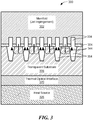
FIG. 3 is a cross-sectional diagram of an example of a transparent heat exchanger system. -
FIG. 4 is a flowchart of an example of a process to fabricate the transparent heat exchanger system ofFIG. 2 . -
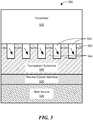
FIG. 5 is a cross-sectional diagram of another example of a transparent heat exchanger system. -
FIG. 6 is a flowchart of an example of a process to fabricate the transparent heat exchanger system ofFIG. 5 . -
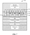
FIG. 7 is a cross-sectional diagram of a further example of a transparent heat exchanger system. -
FIG. 8 is a flowchart of an example of a process to fabricate the transparent heat exchanger system ofFIG. 7 . -
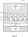
FIG. 9 is a cross-sectional diagram of a still further example of a transparent heat exchanger system. -
FIG. 10 is a flowchart of an example of a process to fabricate the transparent heat exchanger system ofFIG. 9 -
FIG. 11A to 11C are diagrams of examples of a transparent heat exchanger in an optical window. -
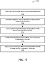
FIG. 12 is a flowchart of an example of a process to fabricate the transparent heat exchanger system ofFIG. 12 . -
FIG. 13 is a flowchart of an example of a process to form an optical bond. -
FIG. 14 is a flowchart of another example of a process to form an optical bond. - Described herein are transparent heat exchangers. In one example, a transparent heat exchanger may include a transparent substrate with one or more fins. In another example, a transparent heat exchanger may include more than one transparent substrate. In a further example, a transparent heat exchanger forming an optical window may include transparent substrates with at least one substrate having one or more fins.
- As used herein the term "transparent" refers to a material's ability to allow wavelengths of light (e.g., visible or infrared), or at least wavelengths of light above or below a particular wavelength, to pass through the material. As used herein transparent material includes semi-transparent material and fully transparent material.
- As used herein, the term "transparent heat exchanger" may be used interchangeably with the term "transparent heatsink."
- Some energy sources generate both thermal energy (sensible heat) and light energy (such as fluorescence, stray pump light, and/or signal light). With prior art (non-transparent heat exchangers), the light energy is converted into thermal energy at the interface between the source and the heat exchanger. The aggregated thermal energy and the newly converted light energy must conduct through the heat exchanger along the same path and into the coolant on the same surfaces. As described herein, the transparent heat exchanger enables improved thermal performance by separating the functions of removing waste heat generated in the source and waste heat generated by light energy emanating from the source. The light emanating from the source may be converted into heat within the bulk coolant, on separate heat exchanger surfaces from those conducting the waste heat, and/or the light may pass completely through the heat exchanger. All cases result in greater heat exchanger performance due to lower heat per unit area of the heat exchanger facesheet and lower heat per unit area at the heat exchanger interface with the coolant.
-
FIG. 1 depicts one example of a transparentheat exchanger system 100. The transparentheat exchanger system 100 includes atransparent heat exchanger 102 that is attached to aheat source 108 and is configured to remove heat from the heat source. In this configuration thetransparent heat exchanger 102 is attached to one side of the heat source. -
FIG. 2 depicts a transparent heat exchanger system 100' in cross-section. The heat exchanger system 100' includes the transparent heat exchanger 102' that at least partially surrounds theheat source 108 and is configured to remove heat from theheat source 108. - In one particular example, the
heat source 108 is a laser system (e.g., a laser amplifier). In another example, theheat source 108 is a mirror. In a further example, theheat source 108 is a lens. - As will be further described herein the
transparent heat exchangers 102, 102' each include at least one transparent substrate and further include at least one of fins formed from transparent material or fluid channels for jet impingement to transfer heat. - Referring to
FIG. 3 , a transparentheat exchanger system 300, in one example, includes a manifold 302, a first thermaloptical interface 304, atransparent substrate 306, a second thermaloptical interface 320 and a heat source 326 (e.g., a laser amplifier). The manifold 302 includes fluid channels (e.g., fluid channels 334) used for jet impingement of a fluid (e.g., coolant) to provide cooling. In some examples herein, a thermal optical interface may be an optical bond that is able to transmit light of a desired wavelength. In some examples herein, a thermal optical interface may be a thin film of fluid. As used herein, a thermal optical interface is an interface that passes both thermal and optical energy thru the interface - The
transparent substrate 306 includes etched troughs (e.g.,fluid channels 354 to carry coolant), which form raised features in thetransparent substrate 306 called fins (e.g., fins 344). Thefins 344 provide an increased heat transfer area. In one example, thetransparent substrate 306 is one of indium phosphate, silicon, silicon carbide, fused silica, sapphire, diamond or any other suitable material or combination of materials. In one example, a coefficient of thermal expansion (CTE) of thetransparent substrate 306 is about equal to the CTE of the heat source 326 (e.g., differing by no more than 10 parts per million per degree Centigrade (ppm/°C)). - In other examples, the manifold 334 may be along one or both ends of the
transparent substrate 306 instead, or the manifold 334 may partially or wholly surround thetransparent substrate 306. - Referring to
FIG. 4 , aprocess 400 is one example of a process to fabricate theheat exchanger system 300. Thefluid channels 334 are etched in the manifold 302 andfluid channels 354 are etched into the transparent substrate 306 (402). Surfaces oftransparent substrate 306 and the manifold 302 are smoothed for optical bonding (406). Thetransparent substrate 306 is bonded to the manifold 302 with thermaloptical interface 304 to form a bonded assembly (412). The surfaces oftransparent substrate 306 and theheat source 326 are smoothed (422). Thetransparent substrate 306 is optically attached (i.e., forming a thermal optical interface that passes thermal and optical energy through the interface) to theheat source 326 with thermal optical interface 324 (426). It should be understood that both surfaces oftransparent substrate 306 may be smoothed at the same step. - In one or more embodiments described herein, various techniques may be used to form a smooth surface. For example, chemical or mechanical planarization of a surface may be accomplished to produce a smooth surface by polishing, etching, or a combination of the two. In some embodiments, the surface may be smoothed by exposing the surface to an abrasive and/or corrosive chemical in conjunction with a polishing pad that is in contact with the surface and is moved relative to the surface. In some embodiments, the surfaces may be smoothed to a surface roughness of less than 25 Angstroms (e.g., between 10 to 25 Angstroms, 5 to 10 Angstroms, less than 5 Angstroms).
- In one or more embodiments described herein, a typical flatness for optics (bonded or unbonded) may be 10% of the wavelength (referred to as lambda/10). In one particular example, for a 1 micrometer wavelength, the flatness of the optics is 100nm.
- Referring to
FIG. 5 , aheat exchanger system 500, in one example, includes afacesheet 502, a first thermaloptical interface 504, atransparent substrate 506, a second thermaloptical interface 520 and a heat source 526 (e.g., a laser amplifier). - The
transparent substrate 506 includes etched troughs (e.g.,fluid channels 554 to carry coolant), which form raised features in thetransparent substrate 506 called fins (e.g., fins 544). Thefins 544 provide an increased heat transfer area. In one example, thetransparent substrate 506 is one of indium phosphate, silicon, silicon carbide, fused silica, sapphire, diamond, germanium, zinc selenide, zinc sulfide or any other suitable material or combination of materials. In one example, a CTE of thetransparent substrate 506 is about equal to the CTE of theheat source 526. - In other examples, the
facesheet 502 may be along one or both ends of thetransparent substrate 506 instead, or thefacesheet 502 may partially or wholly surround thetransparent substrate 506. - Referring to
FIG. 6 , aprocess 600 is one example of a process to fabricate theheat exchanger system 500. Thefluid channels 554 are etched into the transparent substrate 506 (602). Surfaces oftransparent substrate 506 and thefacesheet 502 are smoothed for optical bonding (606). Thetransparent substrate 506 is bonded to thefacesheet 502 with thermaloptical interface 504 to form a bonded assembly (612). The surfaces oftransparent substrate 506 and theheat source 526 are smoothed (622). Thetransparent substrate 506 is optically attached to theheat source 526 with thermal optical interface 520 (626). In one example, it should be understood that both surfaces oftransparent substrate 506 may be smoothed at the same time. - Referring to
FIG. 7 , a transparentheat exchanger system 700, in one example, includes a manifold 702, a first thermaloptical interface 704, a firsttransparent substrate 706, a second thermaloptical interface 708, a second transparent substrate 712 (sometimes called a "transparent facesheet substrate" in this configuration), a third thermaloptical interface 718 and a heat source 722 (e.g., a laser amplifier). The manifold 702 includes fluid channels (e.g., fluid channels 734) used for jet impingement of a fluid (e.g., coolant) to provide cooling. - The first
transparent substrate 706 includes etched troughs (e.g.,fluid channels 754 to carry coolant), which form raised features in the firsttransparent substrate 706 called fins (e.g., fins 744). Thefins 744 provide an increased heat transfer area. In one example, the firsttransparent substrate 706 and the secondtransparent substrate 712 are each one of indium phosphate, silicon, silicon carbide, fused silica, sapphire, diamond, or any other suitable material or combination of materials. The firsttransparent material 706 and the secondtransparent material 712 may be the same or different material. The coefficient of thermal expansion (CTE) of the firsttransparent substrate 706, the CTE of the second transparent substrate and the CTE of theheat source 722 are about equal (e.g., the CTEs of the first transparent substrate, the second transparent substrate and the heat source differ by no more than 10 parts per million per degree Centigrade (ppm/°C) from each other. In some examples, the secondtransparent substrate 712 may be configured to include etched troughs. In some examples, the secondtransparent substrate 712 may be configured to include etched troughs instead of the firsttransparent substrate 706. - Referring to
FIG. 8 , aprocess 800 is one example of a process to fabricate theheat exchanger system 700. Thefluid channels 734 are etched in the manifold 702 andfluid channels 754 are etched into the first transparent substrate 706 (802). Surfaces of the firsttransparent substrate 706 and the secondtransparent substrate 712 are smoothed for optical bonding (808). The firsttransparent substrate 706 is optically bonded to the secondtransparent substrate 712 with thermal optical interface 708 (810). Surfaces of the firsttransparent substrate 706 and the manifold 702 are smoothed for optical bonding (816). The firsttransparent substrate 706 is bonded to the manifold 702 with thermaloptical interface 704 to form a bonded assembly (822). It should be understood that both surfaces of the firsttransparent substrate 706 may be smoothed at the same step. - The surfaces of the second
transparent substrate 712 and theheat source 722 are smoothed (832). The secondtransparent substrate 712 is optically attached to theheat source 722 with thermal optical interface 718 (836). It should be understood that both surfaces of the secondtransparent substrate 712 may be smoothed at the same step. - Referring to
FIG. 9 , a transparentheat exchanger system 900, in one example, includes a manifold 902, a first thermaloptical interface 906, atransparent substrate 912, a second thermaloptical interface 922 and a heat source 926 (e.g., a laser amplifier). The manifold 902 includes etched troughs (e.g., fluid channels 954), which form features in the manifold 902 called fins (e.g., fins 944). Thefins 944 provide an increased heat transfer area. - In one example, the manifold 902 is a transparent material being one of indium phosphate, silicon, silicon carbide, fused silica, sapphire, diamond, or any other suitable material or combination of materials. In one example, the
transparent substrate 912 is one of indium phosphate, silicon, silicon carbide, fused silica, sapphire, diamond, or any other suitable material or combination of materials. In one example, a CTE of thetransparent substrate 912 is about equal to the CTE of theheat source 926. - In other examples, the manifold 902 may be along one or both ends of the
transparent substrate 912 instead, or the manifold 902 may partially or wholly surround thetransparent substrate 912. - Referring to
FIG. 10 , aprocess 1000 is one example of a process to fabricate theheat exchanger system 900. Thefluid channels 954 are etched in the manifold 902 (1002). Surfaces oftransparent substrate 912 and the manifold 902 are smoothed for optical bonding (1008). Thetransparent substrate 912 is optically bonded to the manifold 902 with the first thermaloptical interface 906 to form a bonded assembly (1016). The surfaces oftransparent substrate 912 and theheat source 926 are smoothed (1028). Thetransparent substrate 912 is optically attached to theheat source 926 with the second thermal optical interface 922 (1032). It should be understood that both surfaces of thetransparent substrate 912 may be smoothed at the same step. - Referring to
FIG. 11A , anoptical window 1100 is a transparent heat exchanger that includes a firsttransparent substrate 1102, a thermaloptical interface 1104 and a secondtransparent substrate 1106. The secondtransparent substrate 1106 includes etched troughs (e.g., fluid channels 1154), which form features in the secondtransparent substrate 1106 called fins (e.g., fins 1144). In this configuration, light (e.g., with visible or infrared wavelength 1150) generated by a source (not shown) passes through thewindow 1100. In one example, the firsttransparent substrate 1102 includes at least one of indium phosphate, silicon, silicon carbide, fused silica, sapphire, diamond, or any other suitable material or combination of materials. In one example, the secondtransparent substrate 1106 includes at least one of indium phosphate, silicon, silicon carbide, fused silica, sapphire, diamond, or any other suitable material or combination of materials. In some examples, the firsttransparent substrate 1102 may be configured to include etched troughs. In some examples, the firsttransparent substrate 1102 may be configured to include etched troughs instead of the secondtransparent substrate 1106. - In some examples, a void, vacuum or
air gap 1120 may separate the firsttransparent substrate 1102 from the secondtransparent substrate 1106 in an optical window 1100' (FIG. 11B ). - In some examples, thermal optical interfaces (e.g., thermal
optical interface 1114 and thermal optical interface 1124) may be included on sides of anoptical window 1100" (FIG. 11C ). - In another example, the
optical windows optical windows - Referring to
FIG. 12 , aprocess 1200 is an example of a process to fabricate theoptical window 1100. Thefluid channels 1154 are etched into the second transparent substrate 1106 (1202). Surfaces of the first and secondtransparent substrates transparent substrates bond 1104. The first and secondtransparent substrates - Referring to
FIG. 13 , aprocess 1300 is one example to perform optical bonding described herein in theprocess Process 1300 includes forming oxide surface on the substrates to be bonded (1302) and bonding the substrates to form a covalent bond (1306). - Referring to
FIG. 14 , aprocess 1400 is another example to perform optical bonding described herein in theprocess Process 1400 includes applying transparent solder to substrate surfaces (1402) and bonding the substrates to form a transparent solder bond (1406). - In one example, the heat sources described herein may be from high-power laser systems. The high-power laser systems could be used in a large number of military and commercial applications. The following examples do not limit this disclosure to any particular application.
- The processes described herein are not limited to the specific examples described. For example, the
processes FIGS. 4 ,6 ,8 ,10 and12 to 14 , respectively. Rather, any of the processing blocks ofFIGS. 4 ,6 ,8 ,10 and12 to 14 may be re-ordered, combined or removed, performed in parallel or in serial, as necessary, to achieve the results set forth above. - Elements of different embodiments described herein may be combined to form other embodiments not specifically set forth above. Various elements, which are described in the context of a single embodiment, may also be provided separately or in any suitable subcombination. Other embodiments not specifically described herein are also within the scope of the appended claims.
- Specific examples of the invention are set out as follows:
- 1. A transparent heat exchanger comprising:
- a first transparent substrate optically attached to a heat source;
- one or more fins to transfer heat from the heat source, the one or more fins comprising transparent material; and
- further comprising one of:
- a manifold coupled to the first transparent substrate or
- a facesheet coupled to the first transparent material.
- 2. The transparent heat exchanger of example 1, wherein the manifold is optically bonded to the first transparent substrate.
- 3. The transparent heat exchanger of example 2, wherein the first transparent substrate comprises the one or more fins.
- 4. The transparent heat exchanger of example 1, wherein the manifold comprises channels used to supply coolant to the one or more fins and to return coolant from the one or more fins.
- 5. The transparent heat exchanger of example 1, further comprising a second transparent substrate comprising the one or more fins.
- 6. The transparent heat exchanger of example 5, wherein the second substrate is optically bonded to the first substrate.
- 7. The transparent heat exchanger of example 5, wherein the second substrate is optically bonded to the manifold.
- 8. The transparent heat exchanger of example 5, wherein the second transparent substrate comprises at least one of indium phosphate, silicon, silicon carbide, fused silica, sapphire, germanium, zinc selenide, zinc sulfide, diamond or any combination thereof.
- 9. The transparent heat exchanger of example 1, wherein the first transparent substrate comprises at least one of indium phosphate, silicon, silicon carbide, fused silica, sapphire, germanium, zinc selenide, zinc sulfide, diamond or any combination thereof.
- 10. The transparent heat exchanger of example 1, wherein a coefficient of thermal expansion (CTE) of the first transparent substrate and the CTE of the heat source differ by no more than 10 parts per million per degree Centigrade.
- 11. The transparent heat exchanger of example 1, wherein the manifold is along one or both ends of the transparent substrate.
- 12. The transparent heat exchanger of example 1, wherein the manifold is partially or wholly surround the transparent substrate.
- 13. An optical window comprising:
- a first transparent substrate; and
- a second transparent substrate optically bounded to the first transparent substrate and comprising one or more fins.
- 14. The window of example 13, wherein the window is configured to pass a light signal through the first transparent substrate to the second transparent substrate through the second transparent substrate.
- 15. The optical window of example 13, wherein the first transparent substrate comprises at least one of indium phosphate, silicon, silicon carbide, fused silica, sapphire or diamond.
- 16. The optical window of example 13, wherein the second transparent substrate comprises at least one of indium phosphate, silicon, silicon carbide, fused silica, sapphire or diamond.
- 17. The optical window of example 13, wherein the first transparent substrate and second transparent substrate form a heat exchanger assembly and seal the one or more channels at edges defined by fins,
wherein electromagnetic radiation is passed through the optical window. - 18. A method to fabricate a transparent heat exchanger comprising:
- optically bonding a first transparent substrate to a heat source;
- forming one or more fins to transfer heat from the heat source, the one or more fins comprising transparent material; and
- coupling the first transparent substrate to one of a manifold or a facesheet.
- 19. The method of example 18, wherein forming one or more fins comprises forming one or more fins in one of the first transparent substrate or a second substrate coupled to the heat source and the first substrate to transfer heat from the one or more fins to a coolant in contact with the one or more fins.
- 20. A method to cool a heat source, comprising:
attaching a transparent heat exchanger to the heat source, wherein the transparent heat exchanger comprises:- a first transparent substrate optically attached to the heat source;
- one or more fins to transfer heat from the heat source to a coolant in contact with the one or more fins, the one or more fins comprising transparent material; and
- further comprising one of:
- a manifold coupled to the first transparent substrate or
- a facesheet coupled to the first transparent material.
Claims (15)
- A transparent heat exchanger comprising:a first transparent substrate optically attached to a heat source;one or more fins to transfer heat from the heat source, the one or more fins comprising transparent material; andfurther comprising one of:a manifold coupled to the first transparent substrate ora facesheet coupled to the first transparent material.
- The transparent heat exchanger of claim 1, wherein the manifold comprises channels used to supply coolant to the one or more fins and to return coolant from the one or more fins.
- The transparent heat exchanger of claim 1, further comprising a second transparent substrate comprising the one or more fins.
- The transparent heat exchanger of claim 3, wherein the second substrate is optically bonded to the first substrate, or
wherein the second substrate is optically bonded to the manifold. - The transparent heat exchanger of claim 3, wherein the second transparent substrate comprises at least one of indium phosphate, silicon, silicon carbide, fused silica, sapphire, germanium, zinc selenide, zinc sulfide, diamond or any combination thereof.
- The transparent heat exchanger of claim 1, wherein the first transparent substrate comprises at least one of indium phosphate, silicon, silicon carbide, fused silica, sapphire, germanium, zinc selenide, zinc sulfide, diamond or any combination thereof, and/or
wherein a coefficient of thermal expansion (CTE) of the first transparent substrate and the CTE of the heat source differ by no more than 10 parts per million per degree Centigrade. - The transparent heat exchanger of claim 1, wherein the manifold is along one or both ends of the transparent substrate.
- The transparent heat exchanger of claim 1, wherein the manifold is partially or wholly surround the transparent substrate.
- An optical window comprising:a first transparent substrate; anda second transparent substrate optically bounded to the first transparent substrate and comprising one or more fins.
- The window of claim 9, wherein the window is configured to pass a light signal through the first transparent substrate to the second transparent substrate through the second transparent substrate.
- The optical window of claim 9, wherein the first transparent substrate comprises at least one of indium phosphate, silicon, silicon carbide, fused silica, sapphire or diamond, and/or
wherein the second transparent substrate comprises at least one of indium phosphate, silicon, silicon carbide, fused silica, sapphire or diamond. - The optical window of claim 9, wherein the first transparent substrate and second transparent substrate form a heat exchanger assembly and seal the one or more channels at edges defined by fins,
wherein electromagnetic radiation is passed through the optical window. - A method to fabricate a transparent heat exchanger comprising:optically bonding a first transparent substrate to a heat source;forming one or more fins to transfer heat from the heat source, the one or more fins comprising transparent material; andcoupling the first transparent substrate to one of a manifold or a facesheet.
- The method of claim 13, wherein forming one or more fins comprises forming one or more fins in one of the first transparent substrate or a second substrate coupled to the heat source and the first substrate to transfer heat from the one or more fins to a coolant in contact with the one or more fins.
- A method to cool a heat source, comprising:
attaching a transparent heat exchanger to the heat source, wherein the transparent heat exchanger comprises:a first transparent substrate optically attached to the heat source;one or more fins to transfer heat from the heat source to a coolant in contact with the one or more fins, the one or more fins comprising transparent material;
andfurther comprising one of:a manifold coupled to the first transparent substrate ora facesheet coupled to the first transparent material.
Applications Claiming Priority (3)
| Application Number | Priority Date | Filing Date | Title |
|---|---|---|---|
| US15/285,867 US10401099B2 (en) | 2016-10-05 | 2016-10-05 | Transparent heat exchanger |
| EP17727015.4A EP3523861A1 (en) | 2016-10-05 | 2017-05-05 | Transparent heat exchanger |
| PCT/US2017/031186 WO2018067204A1 (en) | 2016-10-05 | 2017-05-05 | Transparent heat exchanger |
Related Parent Applications (1)
| Application Number | Title | Priority Date | Filing Date |
|---|---|---|---|
| EP17727015.4A Division EP3523861A1 (en) | 2016-10-05 | 2017-05-05 | Transparent heat exchanger |
Publications (1)
| Publication Number | Publication Date |
|---|---|
| EP3910743A1 true EP3910743A1 (en) | 2021-11-17 |
Family
ID=58873858
Family Applications (2)
| Application Number | Title | Priority Date | Filing Date |
|---|---|---|---|
| EP17727015.4A Withdrawn EP3523861A1 (en) | 2016-10-05 | 2017-05-05 | Transparent heat exchanger |
| EP21176313.1A Withdrawn EP3910743A1 (en) | 2016-10-05 | 2017-05-05 | Transparent heat exchanger |
Family Applications Before (1)
| Application Number | Title | Priority Date | Filing Date |
|---|---|---|---|
| EP17727015.4A Withdrawn EP3523861A1 (en) | 2016-10-05 | 2017-05-05 | Transparent heat exchanger |
Country Status (4)
| Country | Link |
|---|---|
| US (2) | US10401099B2 (en) |
| EP (2) | EP3523861A1 (en) |
| IL (1) | IL264181B (en) |
| WO (1) | WO2018067204A1 (en) |
Families Citing this family (2)
| Publication number | Priority date | Publication date | Assignee | Title |
|---|---|---|---|---|
| US10401099B2 (en) | 2016-10-05 | 2019-09-03 | Raytheon Company | Transparent heat exchanger |
| GB201621690D0 (en) * | 2016-12-20 | 2017-02-01 | Element Six Tech Ltd | A heat sink comprising synthetic diamond material |
Citations (2)
| Publication number | Priority date | Publication date | Assignee | Title |
|---|---|---|---|---|
| US5548605A (en) * | 1995-05-15 | 1996-08-20 | The Regents Of The University Of California | Monolithic microchannel heatsink |
| US20160164241A1 (en) * | 2014-12-09 | 2016-06-09 | Raytheon Company | System and method for cooling a laser gain medium using an ultra-thin liquid thermal optical interface |
Family Cites Families (15)
| Publication number | Priority date | Publication date | Assignee | Title |
|---|---|---|---|---|
| KR0137125B1 (en) | 1992-11-16 | 1998-06-15 | 모리시타 요이찌 | Optical waveguide device and manufacturing method |
| US5796766A (en) | 1994-08-23 | 1998-08-18 | Laser Power Corporation | Optically transparent heat sink for longitudinally cooling an element in a laser |
| US5726751A (en) | 1995-09-27 | 1998-03-10 | University Of Washington | Silicon microchannel optical flow cytometer |
| US6284085B1 (en) | 1997-04-03 | 2001-09-04 | The Board Of Trustees Of The Leland Stanford Junior University | Ultra precision and reliable bonding method |
| US6339605B1 (en) * | 2000-02-16 | 2002-01-15 | The Boeing Company | Active mirror amplifier system and method for a high-average power laser system |
| US6902987B1 (en) | 2000-02-16 | 2005-06-07 | Ziptronix, Inc. | Method for low temperature bonding and bonded structure |
| US6480515B1 (en) | 2000-12-15 | 2002-11-12 | Xerox Corporation | Optically transparent, heat conductive fluid heat sink |
| US6810060B2 (en) * | 2001-02-13 | 2004-10-26 | The Boeing Company | High-average power active mirror solid-state laser with multiple subapertures |
| US6859472B2 (en) | 2001-11-13 | 2005-02-22 | Raytheon Company | Multi-jet impingement cooled slab laser pumphead and method |
| US6690696B2 (en) | 2002-06-14 | 2004-02-10 | Raytheon Company | Laser cooling apparatus and method |
| US7472741B2 (en) | 2005-02-09 | 2009-01-06 | Raytheon Company | Foil slot impingement cooler with effective light-trap cavities |
| US20140123578A1 (en) | 2011-03-01 | 2014-05-08 | President And Fellows Of Harvard College | Thermal management of transparent media |
| US8921992B2 (en) | 2013-03-14 | 2014-12-30 | Raytheon Company | Stacked wafer with coolant channels |
| US9502330B1 (en) * | 2015-06-09 | 2016-11-22 | Raytheon Company | Coolant distribution structure for monolithic microwave integrated circuits (MMICs) |
| US10401099B2 (en) | 2016-10-05 | 2019-09-03 | Raytheon Company | Transparent heat exchanger |
-
2016
- 2016-10-05 US US15/285,867 patent/US10401099B2/en active Active
-
2017
- 2017-05-05 EP EP17727015.4A patent/EP3523861A1/en not_active Withdrawn
- 2017-05-05 EP EP21176313.1A patent/EP3910743A1/en not_active Withdrawn
- 2017-05-05 WO PCT/US2017/031186 patent/WO2018067204A1/en not_active Ceased
-
2019
- 2019-01-10 IL IL264181A patent/IL264181B/en unknown
- 2019-07-08 US US16/504,834 patent/US11092392B2/en active Active
Patent Citations (2)
| Publication number | Priority date | Publication date | Assignee | Title |
|---|---|---|---|---|
| US5548605A (en) * | 1995-05-15 | 1996-08-20 | The Regents Of The University Of California | Monolithic microchannel heatsink |
| US20160164241A1 (en) * | 2014-12-09 | 2016-06-09 | Raytheon Company | System and method for cooling a laser gain medium using an ultra-thin liquid thermal optical interface |
Non-Patent Citations (2)
| Title |
|---|
| MARK A. CULPEPPER ET AL: "Liquid-cooled transmissive optical component", SPIE - INTERNATIONAL SOCIETY FOR OPTICAL ENGINEERING. PROCEEDINGS, vol. 3447, 13 November 1998 (1998-11-13), US, pages 54 - 61, XP055393332, ISSN: 0277-786X, ISBN: 978-1-5106-0753-8, DOI: 10.1117/12.331129 * |
| VETROVEC J: "ACTIVE MIRROR AMPLIFIER FOR HIGH-AVERAGE POWER", OPTOMECHATRONIC MICRO/NANO DEVICES AND COMPONENTS III : 8 - 10 OCTOBER 2007, LAUSANNE, SWITZER; [PROCEEDINGS OF SPIE , ISSN 0277-786X], SPIE, BELLINGHAM, WASH, vol. 4270, no. 4270, 23 January 2001 (2001-01-23), pages 45 - 55, XP008006203, ISBN: 978-1-62841-730-2, DOI: 10.1117/12.424677 * |
Also Published As
| Publication number | Publication date |
|---|---|
| EP3523861A1 (en) | 2019-08-14 |
| WO2018067204A1 (en) | 2018-04-12 |
| US10401099B2 (en) | 2019-09-03 |
| US11092392B2 (en) | 2021-08-17 |
| US20190331440A1 (en) | 2019-10-31 |
| IL264181A (en) | 2019-02-28 |
| IL264181B (en) | 2022-03-01 |
| US20180094882A1 (en) | 2018-04-05 |
Similar Documents
| Publication | Publication Date | Title |
|---|---|---|
| US10854795B2 (en) | Method of manufacturing a light emitting device | |
| US11092392B2 (en) | Transparent heat exchanger | |
| CN104097382B (en) | The device of the cooling adhesive layer for showing equipment and the method for detaching panel | |
| JP6551404B2 (en) | Optical glass and method of cutting glass substrate | |
| US9651236B2 (en) | Light emitting device with a heat sink composed of two materials | |
| JP5132534B2 (en) | Manufacturing method of optical components | |
| US10580666B2 (en) | Carrier substrates for semiconductor processing | |
| KR20030041811A (en) | Pellicle and a method of using the same | |
| CN105377549A (en) | Glass structures and methods of creating and processing glass structures | |
| KR102588785B1 (en) | Manufacturing method of semiconductor device | |
| US9762018B2 (en) | System and method for cooling a laser gain medium using an ultra-thin liquid thermal optical interface | |
| KR20210058019A (en) | Apparatus and Method for Separating and Transferring a Transfer Object Using Laser | |
| US20180001416A1 (en) | Nonplanar wafer and method for producing a nonplanar wafer | |
| JP2014201452A (en) | Glass-ceramic joined body | |
| US10685861B2 (en) | Direct optical heating of substrates through optical guide | |
| TWI798244B (en) | Light emitting devices and method of manufacturing the same | |
| JP2017040841A (en) | Optical waveguide device and optical integrated circuit device | |
| US20110201256A1 (en) | Undoped silicon heat spreader window | |
| TW201426063A (en) | Method for manufacturing optical coupler | |
| KR101998920B1 (en) | Microchannel heat sink for micro-gap thermophotovoltaic device | |
| CN111684337B (en) | Method for manufacturing optical multiplexer/demultiplexer | |
| TW202447239A (en) | Method for coating an optically reflective layer on a waveguide and screen printing device | |
| JP2005139016A (en) | Method for producing joined member, and micro chemical chip obtained by using the same | |
| KR102944811B1 (en) | Method and System for finishing Optically Clear Adhesive tape | |
| TWI783530B (en) | Temporarily bonding laminated body and application of wafer thinning preparation method |
Legal Events
| Date | Code | Title | Description |
|---|---|---|---|
| PUAI | Public reference made under article 153(3) epc to a published international application that has entered the european phase |
Free format text: ORIGINAL CODE: 0009012 |
|
| STAA | Information on the status of an ep patent application or granted ep patent |
Free format text: STATUS: THE APPLICATION HAS BEEN PUBLISHED |
|
| AC | Divisional application: reference to earlier application |
Ref document number: 3523861 Country of ref document: EP Kind code of ref document: P |
|
| AK | Designated contracting states |
Kind code of ref document: A1 Designated state(s): AL AT BE BG CH CY CZ DE DK EE ES FI FR GB GR HR HU IE IS IT LI LT LU LV MC MK MT NL NO PL PT RO RS SE SI SK SM TR |
|
| B565 | Issuance of search results under rule 164(2) epc |
Effective date: 20211012 |
|
| STAA | Information on the status of an ep patent application or granted ep patent |
Free format text: STATUS: REQUEST FOR EXAMINATION WAS MADE |
|
| 17P | Request for examination filed |
Effective date: 20220512 |
|
| RBV | Designated contracting states (corrected) |
Designated state(s): AL AT BE BG CH CY CZ DE DK EE ES FI FR GB GR HR HU IE IS IT LI LT LU LV MC MK MT NL NO PL PT RO RS SE SI SK SM TR |
|
| STAA | Information on the status of an ep patent application or granted ep patent |
Free format text: STATUS: EXAMINATION IS IN PROGRESS |
|
| 17Q | First examination report despatched |
Effective date: 20220711 |
|
| RIC1 | Information provided on ipc code assigned before grant |
Ipc: H01S 3/23 20060101ALN20221124BHEP Ipc: G02B 7/18 20210101ALI20221124BHEP Ipc: G02B 7/00 20210101ALI20221124BHEP Ipc: H01S 5/024 20060101ALI20221124BHEP Ipc: H01S 3/04 20060101AFI20221124BHEP |
|
| GRAP | Despatch of communication of intention to grant a patent |
Free format text: ORIGINAL CODE: EPIDOSNIGR1 |
|
| STAA | Information on the status of an ep patent application or granted ep patent |
Free format text: STATUS: GRANT OF PATENT IS INTENDED |
|
| INTG | Intention to grant announced |
Effective date: 20230111 |
|
| STAA | Information on the status of an ep patent application or granted ep patent |
Free format text: STATUS: THE APPLICATION IS DEEMED TO BE WITHDRAWN |
|
| 18D | Application deemed to be withdrawn |
Effective date: 20230523 |