EP3910728A1 - Battery pack - Google Patents
Battery pack Download PDFInfo
- Publication number
- EP3910728A1 EP3910728A1 EP21173789.5A EP21173789A EP3910728A1 EP 3910728 A1 EP3910728 A1 EP 3910728A1 EP 21173789 A EP21173789 A EP 21173789A EP 3910728 A1 EP3910728 A1 EP 3910728A1
- Authority
- EP
- European Patent Office
- Prior art keywords
- hollow conductive
- conductive member
- battery pack
- connector
- output terminal
- Prior art date
- Legal status (The legal status is an assumption and is not a legal conclusion. Google has not performed a legal analysis and makes no representation as to the accuracy of the status listed.)
- Pending
Links
Images





Classifications
-
- H—ELECTRICITY
- H01—ELECTRIC ELEMENTS
- H01M—PROCESSES OR MEANS, e.g. BATTERIES, FOR THE DIRECT CONVERSION OF CHEMICAL ENERGY INTO ELECTRICAL ENERGY
- H01M50/00—Constructional details or processes of manufacture of the non-active parts of electrochemical cells other than fuel cells, e.g. hybrid cells
- H01M50/20—Mountings; Secondary casings or frames; Racks, modules or packs; Suspension devices; Shock absorbers; Transport or carrying devices; Holders
-
- H—ELECTRICITY
- H01—ELECTRIC ELEMENTS
- H01M—PROCESSES OR MEANS, e.g. BATTERIES, FOR THE DIRECT CONVERSION OF CHEMICAL ENERGY INTO ELECTRICAL ENERGY
- H01M10/00—Secondary cells; Manufacture thereof
- H01M10/42—Methods or arrangements for servicing or maintenance of secondary cells or secondary half-cells
- H01M10/46—Accumulators structurally combined with charging apparatus
-
- H—ELECTRICITY
- H01—ELECTRIC ELEMENTS
- H01M—PROCESSES OR MEANS, e.g. BATTERIES, FOR THE DIRECT CONVERSION OF CHEMICAL ENERGY INTO ELECTRICAL ENERGY
- H01M50/00—Constructional details or processes of manufacture of the non-active parts of electrochemical cells other than fuel cells, e.g. hybrid cells
- H01M50/50—Current conducting connections for cells or batteries
- H01M50/543—Terminals
- H01M50/552—Terminals characterised by their shape
- H01M50/553—Terminals adapted for prismatic, pouch or rectangular cells
-
- H—ELECTRICITY
- H01—ELECTRIC ELEMENTS
- H01M—PROCESSES OR MEANS, e.g. BATTERIES, FOR THE DIRECT CONVERSION OF CHEMICAL ENERGY INTO ELECTRICAL ENERGY
- H01M50/00—Constructional details or processes of manufacture of the non-active parts of electrochemical cells other than fuel cells, e.g. hybrid cells
- H01M50/50—Current conducting connections for cells or batteries
- H01M50/543—Terminals
- H01M50/552—Terminals characterised by their shape
- H01M50/561—Hollow metallic terminals, e.g. terminal bushings
-
- H—ELECTRICITY
- H01—ELECTRIC ELEMENTS
- H01R—ELECTRICALLY-CONDUCTIVE CONNECTIONS; STRUCTURAL ASSOCIATIONS OF A PLURALITY OF MUTUALLY-INSULATED ELECTRICAL CONNECTING ELEMENTS; COUPLING DEVICES; CURRENT COLLECTORS
- H01R13/00—Details of coupling devices of the kinds covered by groups H01R12/70 or H01R24/00 - H01R33/00
- H01R13/02—Contact members
- H01R13/10—Sockets for co-operation with pins or blades
- H01R13/11—Resilient sockets
- H01R13/111—Resilient sockets co-operating with pins having a circular transverse section
-
- H—ELECTRICITY
- H01—ELECTRIC ELEMENTS
- H01R—ELECTRICALLY-CONDUCTIVE CONNECTIONS; STRUCTURAL ASSOCIATIONS OF A PLURALITY OF MUTUALLY-INSULATED ELECTRICAL CONNECTING ELEMENTS; COUPLING DEVICES; CURRENT COLLECTORS
- H01R13/00—Details of coupling devices of the kinds covered by groups H01R12/70 or H01R24/00 - H01R33/00
- H01R13/02—Contact members
- H01R13/22—Contacts for co-operating by abutting
- H01R13/24—Contacts for co-operating by abutting resilient; resiliently-mounted
- H01R13/2407—Contacts for co-operating by abutting resilient; resiliently-mounted characterized by the resilient means
-
- H—ELECTRICITY
- H01—ELECTRIC ELEMENTS
- H01R—ELECTRICALLY-CONDUCTIVE CONNECTIONS; STRUCTURAL ASSOCIATIONS OF A PLURALITY OF MUTUALLY-INSULATED ELECTRICAL CONNECTING ELEMENTS; COUPLING DEVICES; CURRENT COLLECTORS
- H01R13/00—Details of coupling devices of the kinds covered by groups H01R12/70 or H01R24/00 - H01R33/00
- H01R13/62—Means for facilitating engagement or disengagement of coupling parts or for holding them in engagement
- H01R13/627—Snap or like fastening
- H01R13/6271—Latching means integral with the housing
- H01R13/6273—Latching means integral with the housing comprising two latching arms
-
- H—ELECTRICITY
- H02—GENERATION; CONVERSION OR DISTRIBUTION OF ELECTRIC POWER
- H02J—ELECTRIC POWER NETWORKS; CIRCUIT ARRANGEMENTS OR SYSTEMS FOR SUPPLYING OR DISTRIBUTING ELECTRIC POWER; SYSTEMS FOR STORING ELECTRIC ENERGY
- H02J7/00—Circuit arrangements for charging or discharging batteries or for supplying loads from batteries
- H02J7/70—Circuit arrangements for charging or discharging batteries or for supplying loads from batteries characterised by the mechanical construction
-
- H—ELECTRICITY
- H01—ELECTRIC ELEMENTS
- H01M—PROCESSES OR MEANS, e.g. BATTERIES, FOR THE DIRECT CONVERSION OF CHEMICAL ENERGY INTO ELECTRICAL ENERGY
- H01M2220/00—Batteries for particular applications
- H01M2220/20—Batteries in motive systems, e.g. vehicle, ship, plane
-
- H—ELECTRICITY
- H01—ELECTRIC ELEMENTS
- H01R—ELECTRICALLY-CONDUCTIVE CONNECTIONS; STRUCTURAL ASSOCIATIONS OF A PLURALITY OF MUTUALLY-INSULATED ELECTRICAL CONNECTING ELEMENTS; COUPLING DEVICES; CURRENT COLLECTORS
- H01R2201/00—Connectors or connections adapted for particular applications
- H01R2201/26—Connectors or connections adapted for particular applications for vehicles
-
- H—ELECTRICITY
- H02—GENERATION; CONVERSION OR DISTRIBUTION OF ELECTRIC POWER
- H02J—ELECTRIC POWER NETWORKS; CIRCUIT ARRANGEMENTS OR SYSTEMS FOR SUPPLYING OR DISTRIBUTING ELECTRIC POWER; SYSTEMS FOR STORING ELECTRIC ENERGY
- H02J7/00—Circuit arrangements for charging or discharging batteries or for supplying loads from batteries
- H02J7/50—Circuit arrangements for charging or discharging batteries or for supplying loads from batteries acting upon multiple batteries simultaneously or sequentially
-
- Y—GENERAL TAGGING OF NEW TECHNOLOGICAL DEVELOPMENTS; GENERAL TAGGING OF CROSS-SECTIONAL TECHNOLOGIES SPANNING OVER SEVERAL SECTIONS OF THE IPC; TECHNICAL SUBJECTS COVERED BY FORMER USPC CROSS-REFERENCE ART COLLECTIONS [XRACs] AND DIGESTS
- Y02—TECHNOLOGIES OR APPLICATIONS FOR MITIGATION OR ADAPTATION AGAINST CLIMATE CHANGE
- Y02E—REDUCTION OF GREENHOUSE GAS [GHG] EMISSIONS, RELATED TO ENERGY GENERATION, TRANSMISSION OR DISTRIBUTION
- Y02E60/00—Enabling technologies; Technologies with a potential or indirect contribution to GHG emissions mitigation
- Y02E60/10—Energy storage using batteries
Definitions
- One or more embodiments relate to a battery pack.
- secondary batteries are batteries capable of being charged and discharged, unlike primary batteries that are not capable of being charged. Secondary batteries are used as energy sources for mobile devices, electric vehicles, hybrid vehicles, and uninterruptible power supplies, and may be used in the form of a single battery cell depending on the type of external device applied. Secondary batteries are also used in the form of a battery pack in which a plurality of battery cells are connected and grouped into one unit.
- Small mobile devices such as mobile phones can operate for a certain period of time with the output and capacity of a single cell, but when long-term driving or high-power driving is required, such as electric vehicles and hybrid vehicles that consume a lot of power, the battery pack is preferred due to problems of output and capacity, and the battery pack can increase the output voltage or output current depending on the number of built-in battery cells.
- One or more embodiments include a battery pack in which a connection structure between an input/output terminal connected to one group of battery cells and a connector connected to the external load, the external charger or another group of battery cells, is enhanced so that the connection structure may be simplified, the number of components and cost may be reduced and the reliability of an electrical connection may be enhanced.
- a battery pack includes a battery cell, an input/output terminal to/from which a charging/discharging current of the battery cell is inputted/outputted, and a connector detachably connected to the input/output terminal, wherein the input/output terminal includes a first hollow conductive member protruding in a first direction and a second hollow conductive member protruding to surround an outer periphery of the first hollow conductive member, the connector includes a central guide protruding in a second direction opposite to the first direction and a third hollow conductive member protruding to surround the outer periphery of the central guide, the central guide is fitted into a hollow portion of the first hollow conductive member, and the third hollow conductive member is fitted into a recess space between the first and second hollow conductive members and is electrically connected to the first and second hollow conductive members by interposing an elastic connection member arranged in the recess space.
- the elastic connection member may include a disk member and an inner ring elastic piece and an outer ring elastic piece protruding from an inner ring and an outer ring of the disk member, respectively, in the first direction.
- the inner ring elastic piece may come into contact with an outer circumference of the first hollow conductive member and an inner circumference of the third hollow conductive member, and the outer ring elastic piece may come into contact with an outer circumference of the third hollow conductive member and an inner circumference of the second hollow conductive member.
- a plurality of elastic contact portions may be bent so as to protrude toward the outer circumference of the first hollow conductive member or the inner circumference of the third hollow conductive member in a longitudinal direction of the inner ring elastic piece.
- a plurality of elastic contact portions may be bent so as to protrude toward the outer circumference of the third hollow conductive member or the inner circumference of the second hollow conductive member in a longitudinal direction of the outer ring elastic piece.
- the disk member may include a connection piece formed between the inner ring and the outer ring of the disk member so as to connect therebetween.
- connection piece may come into contact with a longitudinal cross-section of the third hollow conductive member in the second direction.
- connection piece may include an elastic contact portion having a protruding shape between the inner ring and the outer ring of the disk member.
- the inner ring elastic piece, the outer ring elastic piece, and the connection piece of the elastic connection member may be formed as a strip member integrally formed.
- the strip member may form the connection piece between the inner ring and the outer ring, the inner ring elastic piece that is bent to surround the inner ring from the connection piece and may protrude in the first direction, and an outer ring elastic piece that is bent to surround the outer ring from the connection piece and protrudes in the first direction.
- a cutting portion may be formed at a position in a circumferential direction of the disk member.
- An insulating protective cap may be formed at an end portion of a central guide in the second direction.
- An end portion of the central guide or an end of the protective cap may further protrude than an end portion of the third hollow conductive member in the second direction.
- the third hollow conductive member of the connector may be fitted into a recess space between the first and second hollow conductive members and of the input/output terminal.
- the input/output terminal may further include an insulating housing that surrounds an outer periphery of the second hollow conductive member and has a coupling portion for sliding coupling with the connector thereon.
- the coupling portion may be formed in pair at two positions facing each other in a circumferential direction of the insulating housing.
- the coupling portion may include a pair of guide ribs configured to guide sliding of the connector, and a locking jaw formed between the pair of guide ribs.
- the connector may further include an insulating cap that surrounds an outer periphery of the third hollow conductive member and has a lever member for detachable coupling with the input/output terminal.
- the lever member may be formed in pair at facing positions in a circumferential direction of the insulating cap and may be formed at a position corresponding to the coupling portion of the insulating housing.
- the lever member may include one end on which an operation portion is formed, and the other end on which the coupling hook fitted into the locking jaw of the insulating housing according to an operation of the operation portion is formed.
- the lever member may , through a first operation of pulling the pair of operation portions formed at one end position of the lever member toward each other, the pair of the coupling hooks formed at the other end position may be retreated in a direction away from each other, and the first operation on the pair of operation portions formed at one end position of the lever member may be released according to sliding assembly of the insulating cap, so that the pair of coupling hooks formed at the other end approach each other and are coupled to the locking jaw of the insulating housing.
- the lever member may further include a hinge portion formed between the operation portion at one end position and the coupling hook at the other end position. a pair of operation portions at one end position and a pair of coupling hooks at the other end position may approach or retreat in opposite directions with respect to the hinge portion.
- the lever member may be separated from a main body of the insulating cap through the cutting portion and may be connected to the main body of the insulating cap through the hinge portion.
- the central guide and the third hollow conductive member may protrude from the base portion of the connector in the second direction, and a screw member for coupling a base portion and a conductive bar may protrude from the base portion of the connector in the first direction.
- the conductive bar may form a charge/discharge path on which a charging/discharging current flows, between the plurality of battery cells and an external load, an external charger, or another plurality of batter cells.
- FIG. 1 is an exploded perspective view for describing a battery pack according to an embodiment.
- FIG. 2 is a perspective view of a connection structure between an input/output terminal and a connector shown in FIG. 1 ;
- FIG. 3 is an exploded perspective view of an input/output terminal shown in FIG. 2 .
- FIG. 4 is a cross-sectional view of the input/output terminal taken along line IV-IV of FIG. 2 .
- FIG. 5 is a perspective view of an elastic connection member shown in FIG. 3 .
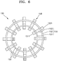
- FIG. 6 is a plan view of the elastic connection member shown in FIG. 3 .
- FIG. 7 is another perspective view of a connection structure between the input/output terminal and the connector shown in FIG. 1 .
- FIG. 1 is an exploded perspective view for describing a battery pack according to an embodiment.
- FIG. 2 is a perspective view of a connection structure between an input/output terminal and a connector shown in FIG. 1 ;
- FIG. 3 is an exploded perspective view of
- FIG. 8 is a cross-sectional view of a connector taken along line VIII-VIII of FIG. 7 .
- FIG. 9 is another perspective view of a connection structure between the input/output terminal and the connector shown in FIG. 1 .
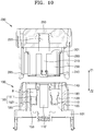
- FIGS. 10 and 11 are cross-sectional views of the input/output terminal and the connector taken along line X-X of FIG. 9 , respectively, illustrating a state before and after connection.
- a battery pack may include a plurality of battery cells 10 electrically connected to each other, an input/output terminal 100 through which charging/discharging currents of the plurality of battery cells 10 are inputted/outputted, and a connector 200 detachably connected to the input/output terminal 100.
- the battery pack may include a plurality of battery cells 10.
- the plurality of battery cells 10 that constitute the battery pack may be electrically connected to each other via a bus bar 15.
- the adjacent battery cells 10 may be electrically connected to each other via the bus bar 15.
- the input/output terminal 100 may be connected to both-end battery cells 10 among the plurality of battery cells 10 electrically connected to each other.
- the input/output terminal 100 may be directly connected to an electrode having a lowest potential of one end of the battery cell 10 forming both ends of a charge/discharge path of the battery cells 10 electrically connected to each other and an electrode having a highest potential of the other end of the battery cell 10, or may be connected to the bus bar 15 connected to the electrode of the lowest potential and the electrode of the highest potential.
- the input/output terminal 100 and the connector 200 may be detachably coupled and electrically connected to each other, and the input/output terminal 100 connected to a group of the battery cells 10, an external load (not shown), an external charger (not shown), or the connector 200 (a conductive bar 250 of the connector 200) connected to another group of the battery cells 10 may be connected to each other so that the charge/discharge path of the battery cell 10 may be provided.
- the input/output terminal 100 may include a base portion 101 formed in a plate shape, a first hollow conductive member 110 protruding from the base portion 101 in a first direction Z1 and protruding from a central position of the base portion 101, and a second hollow conductive member 120 protruding to surround an outer periphery of the first hollow conductive member 110.
- the first and second hollow conductive members 110 and 120 may be formed in a concentric circle shape on the base portion 101 and may protrude in parallel in the first direction Z1 in the concentric circular shape. In this way, the first hollow conductive member 110 and the second hollow conductive member 120 may be concentric cylinders.
- first hollow conductive member 110 may be formed in a circular shape along a first radius from the central position of the base portion 101
- second hollow conductive member 120 may be formed in a circular shape along a second radius from the central position of the base portion 101.
- first and second hollow conductive members 110 and 120 may be formed in a circular shape generally along the first and second radii, but may include a portion partially deviating from a circular trajectory, rather than being formed in a completely circular shape following the first and second radii.
- An insulating protective cap 140 may be formed at an end portion of the first hollow conductive member 110 in the first direction Z1.
- the protective cap 140 may surround the end portion of the first hollow conductive member 110 and may insulate the end portion of the first hollow conductive member 110, thereby eliminating the risk of electric shock through the input/output terminal 100. For example, even if an external foreign substance or a part of the human body comes into contact with the end portion of the first hollow conductive member 110 in the first direction Z1, electricity through the external foreign substance or the human body may be prevented through the insulating protective cap 140 surrounding the end portion of the first hollow conductive member 110, and the risk of electric shock may be blocked.
- the end portion of the first hollow conductive member 110 on which the protective cap 140 is formed may be formed at a position further protruding in the first direction Z1 than the end portion of the second hollow conductive member 120.
- the end portion of the first hollow conductive member 110 or an end of the protective cap 140 may further protrude than the end portion of the second hollow conductive member 120 in the first direction Z1.
- a recess space R may be formed between the first and second hollow conductive members 110 and 120.
- the recess space R may correspond to a space between an outer circumference of the first hollow conductive member 110 and an inner circumference of the second hollow conductive member 120.
- the recess space R may be formed in a space having a hollow cylindrical shape formed between the first hollow conductive member 110 having a first radius and the second hollow conductive member 120 having a second radius.
- the hollow cylindrical shaped space may be defined as a space between an inner circumference of the first radius and an outer circumference of the second radius.
- an elastic connection member 150 may be seated in the recess space R.
- the elastic connection member 150 may include a disk member 155 arranged in parallel on the base portion 101, and an inner ring elastic piece 1511 and an outer ring elastic piece 1521, which protrude from an inner ring 151 and an outer ring 152 of the disk member 155, respectively, in the first direction Z1.
- the inner ring elastic piece 1511 may come into contact with an outer circumference of the first hollow conductive member 110
- the outer ring elastic piece 1521 may come into contact with an inner circumference of the second hollow conductive member 120.
- a third hollow conductive member 230 of the connector 200 may be inserted into the recess space R, and a conductive connection between the first and second hollow conductive members 110 and 120 may be formed through the elastic connection member 150 seated in the recess space R while the third hollow conductive member 230 is accommodated in the recess space R between the first and second hollow conductive members 110 and 120. That is, the inner ring elastic piece 1511 of the elastic connection member 150 may be interposed between the first and third hollow conductive members 110 and 230 and between the outer circumference of the first hollow conductive member 110 and the inner circumference of the third hollow conductive member 230. Also, the outer ring elastic piece 1521 of the elastic connection member 150 may be interposed between the second and third hollow conductive members 120 and 230 and between the outer circumference of the third hollow conductive member 230 and the inner circumference of the second hollow conductive member 120.
- the first and third hollow conductive members 110 and 230 may form a conductive connection by interposing the inner ring elastic piece 1511 therebetween.
- a plurality of elastic contact portions may be formed in a longitudinal direction of the inner ring elastic piece 1511.
- a plurality of elastic contact portions that are bent to protrude toward the outer circumference of the first hollow conductive member 110 or the inner circumference of the third hollow conductive member 230 may be formed in the longitudinal direction of the inner ring elastic piece 1151.
- the plurality of elastic contact portions 1511a may protrude in a radial direction in which the first and third hollow conductive members 110 and 230 face each other and may form contact with any one of the first and third hollow conductive members 110 and 230.
- an elastic contact portion 1511a that comes into contact with an outer circumference of the first hollow conductive member 110 and an elastic contact portion 1511a that comes into contact with an inner circumference of the third hollow conductive member 230 may be formed at different positions in the longitudinal direction of the inner ring elastic piece 1511.
- the second and third hollow conductive members 120 and 230 may form a conductive connection by interposing the outer ring elastic piece 1521.
- a plurality of elastic contact portions may be formed in the longitudinal direction of the outer ring elastic piece 1521.
- a plurality of elastic contact portions that are bent to protrude toward the outer circumference of the third hollow conductive member 230 or the inner circumference of the second hollow conductive member 120 may be formed in the longitudinal direction of the outer ring elastic piece 1521.
- the plurality of elastic contact portions 1521a may protrude in a radial direction in which the second and third hollow conductive members 120 and 230 face each other, and may form contact with any one of the second and third hollow conductive members 120 and 230.
- an elastic contact portion 1521a that comes into contact with the outer circumference of the third hollow conductive member 230 and an elastic contact portion 1521a that comes into contact with the inner circumference of the second hollow conductive member 120 may be formed in the longitudinal direction of the outer ring elastic piece 1521.
- the inner ring elastic piece 1511 and the outer ring elastic piece 1521 may be formed at different positions by interposing the disk member 155 therebetween.
- a plurality of inner ring elastic pieces 1511 and a plurality of outer ring elastic pieces 1521 may be formed in the circumferential direction of the disk member 155 at positions in which they face each other.
- the inner ring elastic piece 1511 may include a plurality of inner ring elastic pieces 1511 formed at positions in which they are equally divided in the circumferential direction along the inner ring 151 of the disk member 155.
- the outer ring elastic piece 1521 may include a plurality of outer ring elastic pieces 1521 formed at positions in which they are equally divided in the circumferential direction along the outer ring 152 of the disk member 155.
- connection piece 153 for connecting the inner ring 151 and the outer ring 152 of the disk member 155 may be formed between the inner ring 151 and the outer ring 152 of the disk member 155. As shown in FIGS. 10 and 11 , the connection piece 153 may come into contact with a longitudinal cross-section of the third hollow conductive member 230 in the second direction Z2. To this end, the connection piece 153 may include an elastic contact portion 153a formed to protrude in the first direction Z1. For example, the connection piece 153 may include an elastic contact portion 153a that protrudes in the first direction Z1 between the inner ring 151 and the outer ring 152 of the disk member 155.
- the inner ring elastic piece 1511, the outer ring elastic piece 1521, and the connection piece 153 of the elastic connection member 150 may be formed as a strip member 158 integrally formed.
- the strip member 158 may form the connection piece 153 between the inner ring 151 and the outer ring 152, the inner ring elastic piece 1511 that is bent to surround the inner ring 151 from the connection piece 153 and protrudes in the first direction Z1, and an outer ring elastic piece 1521 that is bent to surround the outer ring 152 from the connection piece 153 and protrudes in the first direction Z1.
- the strip member 158 may include a plurality of elastic contact portions 1511a, 1521a, and 153a in the longitudinal direction, and the strip member 158 may come into contact with the first through third hollow conductive members 110, 120, and 230 through the elastic contact portions 1511a, 1521a, and 153a formed at different positions.
- the strip member 158 may have approximately rectangular cross-sections and when a relatively long side of the strip member 158 among the rectangular cross-sections is bent, the strip member 158 may surround the inner ring 151 and the outer ring 152 or, when the long side of the strip member 158 is bent, the strip member 158 may form the elastic contact portions 1511a, 1521a, and 153a.
- a bent portion 155' may be formed at a position in the circumferential direction of the disk member 155.
- the circumferential length of the disk member 155 may be variably reduced through the bent portion 155'.
- both ends of the disk member 155 divided through the bent portion 155' overlap each other, and the circumferential length of the disk member 155 may be reduced to be suitable for the recess space R, and a clearance between the disk member 155 and the recess space R may be provided through the bent portion 155'.
- the elastic connection member 150 may be arranged in the recess space R between the first and second hollow conductive members 110 and 120. With respect to the position of the elastic connection member 150, the disk member 155 of the elastic connection member 150 may be supported on the bottom of the recess space R, and ends 1511e and 1521e of the inner ring elastic piece 1511 and the outer ring elastic piece 1521 that protrude from the disk member 155 in the first direction Z1 may be fitted into a seating groove (see 110r of FIG. 4 ) formed in the outer circumference of the first hollow conductive member 110 and a seating groove (see 120r of FIG. 4 ) formed in the inner circumference of the second hollow conductive member 120, respectively, and may be fixed in position so that the disk member 155 of the elastic connection member 150 does not flow in the recess space R.
- a seating groove see 110r of FIG. 4
- a seating groove see 120r of FIG. 4
- the input/output terminal 100 may include an insulating housing 180 that surrounds the outer periphery of the second hollow conductive member 120.
- the insulating housing 180 may function to electrically insulate and protect a component for forming an electrical connection, such as the first and second hollow conductive members 110 and 120 formed inside the input/output terminal 100 or the elastic connection member 150.
- the insulating housing 180 may be formed in an approximately concentric circular shape with the first and second hollow conductive members 110 and 120 so as to surround the outer peripheries of the first and second hollow conductive members 110 and 120.
- a coupling portion 183 for coupling with the connector 200 may be formed on an outer wall of the insulating housing 180.
- the coupling portion 183 may be formed in pairs at two positions facing each other in the circumferential direction of the insulating housing 180.
- the coupling portion 183 may include a pair of guide ribs 181 for guiding a coupling hook 285 of the connector 200 that is slidably coupled along the coupling portion 183 and a locking projection 185 formed between the pair of guide ribs 181.
- the locking jaw 185 may be formed in a stepped step shape to form fastening with the coupling hook 285 that slides along the pair of guide ribs 181.
- the outer wall of the insulating housing 180 may be formed in a generally cylindrical shape, and may be formed in a flatly chamfered shape at the position of the coupling portion 183 in which the locking jaw 185 is formed.
- the insulating housing 180 may surround the outer periphery of the second hollow conductive member 120, and a free space may be formed provided between the insulating housing 180 and the second hollow conductive member 120 so that deformation due to the pressing of the coupling hook 285 slidingly coupled along the outer wall of the insulating housing 180 may be accommodated in the free space.
- the locking jaw 185 of the input/output terminal 100 and the coupling hook 285 of the connector 200 may form physical coupling detachable while sliding with respect to each other, for example, hook coupling.
- the first and second hollow conductive members 110 and 120 of the input/output terminal 100 and the third hollow conductive member 230 of the connector 200 that are slidably coupled to each other may be electrically connected to each other by interposing the elastic connection member 150 therebetween.
- the input/output terminal 100 and the connector 200 may form a physical connection and an electrical connection through sliding coupling to each other.
- the connector 200 may include a base portion 201 formed in an approximately plate shape, a central guide 210 that protrudes from the base portion 201 in a second direction Z2 opposite to the first direction Z1 and protrudes from the central position of the base portion 201, and a third hollow conductive member 230 that protrudes to surround the outer periphery of the central guide 210.
- the central guide 210 and the third hollow conductive member 230 may protrude in parallel with each other in the second direction Z2.
- the central guide 210 may be fitted into a hollow portion 110' of the first hollow conductive member 110 of the input/output terminal 100 and may be guided so that sliding coupling between the connector 200 including the central guide 210 and the input terminal 100 including the first hollow conductive member 110 may not be misaligned through fitting coupling between the central guide 210 and the first hollow conductive member 110.
- An insulating protective cap 240 may be formed at an end portion of the central guide 210 in the second direction Z2.
- the protective cap 240 may surround the end portion of the central guide 210 and may insulate the end portion of the central guide 210, thereby eliminating the risk of electric shock through the connector 200. For example, even if an external foreign substance or a part of the human body is in contact with the end portion of the central guide 210 in the second direction Z2, electricity through the external foreign substance or the human body may be prevented, and the risk of electric shock may be blocked through the insulating protective cap 240 that surrounds the end portion of the central guide 210.
- the end portion of the central guide 210 on which the protective cap 240 is formed may be formed at a position that further protrudes in the second direction Z2 than the end portion of the third hollow conductive member 230.
- the end portion of the central guide 210 or the end of the protective cap 240 may protrude further than the end portion of the third hollow conductive member 230 in the second direction Z2.
- the third hollow conductive member 230 may be fitted into the recess space R provided between the first and second hollow conductive members 110 and 120 and may form an electrical connection with the first and second hollow conductive members 110 and 120 by interposing the elastic connection member 150 arranged in the recess space R.
- the third hollow conductive member 230 may be formed in a generally concentric circular shape with the first and second hollow conductive members 110 and 120 so as to be fitted between the outer circumference of the first hollow conductive member 110 and the inner circumference of the second hollow conductive member 120.
- the first through third hollow conductive members 110,120,230 may be formed in a generally circular shape, but may include a portion partially deviating from the circular trajectory, rather than being formed in a complete circular shape of a concentric circle.
- the third hollow conductive member 230 of the connector 200 is fitted into the recess space R between the first and second hollow conductive members 110 and 120 of the input/output terminal 100 so that the connector 200 and the input/output terminal 100 may be electrically connected to each other.
- the end portion (or the protective cap 240 formed at the end portion of the central guide 210) of the central guide 210 may be formed in a more protruding shape than the end portion of the third hollow conductive member 230.
- the third hollow conductive member 230 may be fitted into the input/output terminal 100 (the recess space R between the first and second hollow conducive members 110 and 120), and through this assembly structure, assembly between the input/output terminal 100 and the connector 200 may not deviate from a sliding trajectory according to the guidance of the central guide 210.
- the connector 200 may include an insulating cap 280 that surrounds the outer periphery of the third hollow conductive member 230.
- the insulating cap 280 may function to electrically insulate and protect a component for forming an electrical connection, such as the central guide 210 or the third hollow conductive member 230 formed inside the connector 200.
- the insulating cap 280 may include a portion formed in an approximately concentric circular shape with the third hollow conductive member 230 so as to surround the outer periphery of the third hollow conductive member 230.
- the connector 200 and the input/output terminal 100 may be coupled to each other so that the insulating cap 280 of the connector 200 cover the outer wall of the insulating housing 180 of the input/output terminal 100.
- the insulating cap 280 and the insulating housing 180 may be detachably coupled to each other.
- a lever member 283 for providing detachable coupling with the insulating housing 180 may be formed on the insulating cap 280.
- the lever member 283 may include one end on which an operation portion 281 is formed, and the other end on which the coupling hook 285 is fitted into the locking jaw 185 of the insulating housing 180 according to the operation of the operation portion 281.
- the lever member 283 may be formed in pairs at positions facing each other in the circumferential direction of the insulating cap 280, and the lever member 283 of the insulating cap 280 may be formed at a position corresponding to the coupling portion 183 of the insulating cap 180.
- the pair of the coupling hooks 285 formed at the other end position may be retreated in a direction away from each other, and after the coupling hook 285 of the insulating cap 280 reaches the position of the locking jaw 185 of the insulating housing 180, the first operation on the pair of operation portions 281 formed at one end position of the lever member 283 may be released according to sliding assembly of the insulating cap 280 and the insulating housing 180, so that the pair of coupling hooks 285 formed at the other end approach each other and are coupled to the locking jaw 185 of the insulating housing 180 and thus coupling between the insulating cap 280 and the insulating housing 180 may be performed.
- the lever member 283 may further include a hinge portion H formed between the operation portion 281 at one end position and the coupling hook 285 at the other end position, and the pair of operation portions 281 at one end position and the pair of coupling hooks 285 at the other end position may approach or retreat in opposite directions, with respect to the hinge portion H.
- the lever member 283 may be separated from a main body of the insulating cap 280 through a cutting portion C. Thus, the approaching or retreating motion of the pair of coupling hooks 285 with respect to each other according to the first operation of the lever member 283 and releasing of the first operation may be performed.
- the lever member 283 may be connected to the main body of the insulating cap 280 through the hinge portion H.
- the lever member 283 may be formed as a part of the insulating cap 280 through the hinge portion H.
- One-end operation portion 281 and the other-end coupling hook 285 formed at opposite sides with respect to the hinge portion H may be linked in opposite directions.
- the central guide 210 and the third hollow conductive member 230 may be electrically connected to the conductive member 250 through the base portion 201 for providing a support base thereof.
- the base portion 201 and the conductive bar 250 may be connected to each other through screw coupling.
- the central guide 210 and the third hollow conductive member 230 may protrude from the base portion 201 in the second direction Z2, and a screw member 220 may protrude in the first direction Z1 opposite to the second direction Z2, and the base portion 201 and the conductive bar 250 may be electrically connected to each other through the screw member 220 protruding from the base portion 201.
- the connector 200 may be electrically connected to an external load, an external charger, or another group of battery cells 10 through the conductive bar 250 and may be coupled to the input/output terminal 100 connected to one group of battery cells 10 so that the input/output terminal 100 and the connector 200 or the conductive bar 250 of the connector 200 may form a charge/discharge path of the battery cell 10.
- the conductive bar 250 may form a charge/discharge path on which a charging/discharging current flows between one group of battery cells 10 and the external load, the external charger, or another group of battery cells 10.
- a connection structure between an input/output terminal connected to one group of battery cells and a connector connected to the external load, the external charger or another group of battery cells is enhanced so that the connection structure may be simplified, the number of components and cost may be reduced and the reliability of an electrical connection may be enhanced.
Landscapes
- Chemical & Material Sciences (AREA)
- Chemical Kinetics & Catalysis (AREA)
- Electrochemistry (AREA)
- General Chemical & Material Sciences (AREA)
- Engineering & Computer Science (AREA)
- Manufacturing & Machinery (AREA)
- Power Engineering (AREA)
- Connection Of Batteries Or Terminals (AREA)
- Battery Mounting, Suspending (AREA)
Abstract
Description
- One or more embodiments relate to a battery pack.
- Generally, secondary batteries are batteries capable of being charged and discharged, unlike primary batteries that are not capable of being charged. Secondary batteries are used as energy sources for mobile devices, electric vehicles, hybrid vehicles, and uninterruptible power supplies, and may be used in the form of a single battery cell depending on the type of external device applied. Secondary batteries are also used in the form of a battery pack in which a plurality of battery cells are connected and grouped into one unit.
- Small mobile devices such as mobile phones can operate for a certain period of time with the output and capacity of a single cell, but when long-term driving or high-power driving is required, such as electric vehicles and hybrid vehicles that consume a lot of power, the battery pack is preferred due to problems of output and capacity, and the battery pack can increase the output voltage or output current depending on the number of built-in battery cells.
- One or more embodiments include a battery pack in which a connection structure between an input/output terminal connected to one group of battery cells and a connector connected to the external load, the external charger or another group of battery cells, is enhanced so that the connection structure may be simplified, the number of components and cost may be reduced and the reliability of an electrical connection may be enhanced.
- According to one or more embodiments, a battery pack includes
a battery cell, an input/output terminal to/from which a charging/discharging current of the battery cell is inputted/outputted, and a connector detachably connected to the input/output terminal, wherein
the input/output terminal includes a first hollow conductive member protruding in a first direction and a second hollow conductive member protruding to surround an outer periphery of the first hollow conductive member,
the connector includes a central guide protruding in a second direction opposite to the first direction and a third hollow conductive member protruding to surround the outer periphery of the central guide,
the central guide is fitted into a hollow portion of the first hollow conductive member, and
the third hollow conductive member is fitted into a recess space between the first and second hollow conductive members and is electrically connected to the first and second hollow conductive members by interposing an elastic connection member arranged in the recess space. - The elastic connection member may include a disk member and an inner ring elastic piece and an outer ring elastic piece protruding from an inner ring and an outer ring of the disk member, respectively, in the first direction.
- The inner ring elastic piece may come into contact with an outer circumference of the first hollow conductive member and an inner circumference of the third hollow conductive member, and
the outer ring elastic piece may come into contact with an outer circumference of the third hollow conductive member and an inner circumference of the second hollow conductive member. - A plurality of elastic contact portions may be bent so as to protrude toward the outer circumference of the first hollow conductive member or the inner circumference of the third hollow conductive member in a longitudinal direction of the inner ring elastic piece.
- A plurality of elastic contact portions may be bent so as to protrude toward the outer circumference of the third hollow conductive member or the inner circumference of the second hollow conductive member in a longitudinal direction of the outer ring elastic piece.
- The disk member may include a connection piece formed between the inner ring and the outer ring of the disk member so as to connect therebetween.
- The connection piece may come into contact with a longitudinal cross-section of the third hollow conductive member in the second direction.
- The connection piece may include an elastic contact portion having a protruding shape between the inner ring and the outer ring of the disk member.
- The inner ring elastic piece, the outer ring elastic piece, and the connection piece of the elastic connection member may be formed as a strip member integrally formed.
- While consecutively surrounding the inner ring and the outer ring arranged in a concentric circular shape, the strip member may form the connection piece between the inner ring and the outer ring, the inner ring elastic piece that is bent to surround the inner ring from the connection piece and may protrude in the first direction, and an outer ring elastic piece that is bent to surround the outer ring from the connection piece and protrudes in the first direction.
- A cutting portion may be formed at a position in a circumferential direction of the disk member.
- An insulating protective cap may be formed at an end portion of a central guide in the second direction.
- An end portion of the central guide or an end of the protective cap may further protrude than an end portion of the third hollow conductive member in the second direction.
- In the connector and the input/output terminal approaching each other in the first and second directions relative to each other, after the central guide of the connector is fitted into the hollow portion of the first hollow conductive member of the input/output terminal, the third hollow conductive member of the connector may be fitted into a recess space between the first and second hollow conductive members and of the input/output terminal.
- The input/output terminal may further include an insulating housing that surrounds an outer periphery of the second hollow conductive member and has a coupling portion for sliding coupling with the connector thereon.
- The coupling portion may be formed in pair at two positions facing each other in a circumferential direction of the insulating housing.
- The coupling portion may include
a pair of guide ribs configured to guide sliding of the connector, and
a locking jaw formed between the pair of guide ribs. - The connector may further include an insulating cap that surrounds an outer periphery of the third hollow conductive member and has a lever member for detachable coupling with the input/output terminal.
- The lever member may be formed in pair at facing positions in a circumferential direction of the insulating cap and may be formed at a position corresponding to the coupling portion of the insulating housing.
- The lever member may include one end on which an operation portion is formed, and the other end on which the coupling hook fitted into the locking jaw of the insulating housing according to an operation of the operation portion is formed.
- The lever member may
, through a first operation of pulling the pair of operation portions formed at one end position of the lever member toward each other, the pair of the coupling hooks formed at the other end position may be retreated in a direction away from each other, and
the first operation on the pair of operation portions formed at one end position of the lever member may be released according to sliding assembly of the insulating cap, so that the pair of coupling hooks formed at the other end approach each other and are coupled to the locking jaw of the insulating housing. - The lever member may further include a hinge portion formed between the operation portion at one end position and the coupling hook at the other end position.
a pair of operation portions at one end position and a pair of coupling hooks at the other end position may approach or retreat in opposite directions with respect to the hinge portion. - The lever member may be separated from a main body of the insulating cap through the cutting portion and may be connected to the main body of the insulating cap through the hinge portion.
- The central guide and the third hollow conductive member may protrude from the base portion of the connector in the second direction, and
a screw member for coupling a base portion and a conductive bar may protrude from the base portion of the connector in the first direction. - The conductive bar may form a charge/discharge path on which a charging/discharging current flows, between the plurality of battery cells and an external load, an external charger, or another plurality of batter cells.
- At least some of the above and other features of the invention are set out in the claims.
- The subject-matter of the present disclosure is best understood with reference to the accompanying figures, in which:
-
FIG. 1 is an exploded perspective view for describing a battery pack according to an embodiment; -
FIG. 2 is a perspective view of a connection structure between an input/output terminal and a connector shown inFIG. 1 ; -
FIG. 3 is an exploded perspective view of an input/output terminal shown inFIG. 2 ; -
FIG. 4 is a cross-sectional view of the input/output terminal taken along line IV-IV ofFIG. 2 ; -
FIG. 5 is a perspective view of an elastic connection member shown inFIG. 3 ; -
FIG. 6 is a plan view of the elastic connection member shown inFIG. 3 ; -
FIG. 7 is another perspective view of a connection structure between the input/output terminal and the connector shown inFIG. 1 ; -
FIG. 8 is a cross-sectional view of a connector taken along line VIII-VIII ofFIG. 7 ; -
FIG. 9 is another perspective view of a connection structure between the input/output terminal and the connector shown inFIG. 1 ; and -
FIGS. 10 and11 are cross-sectional views of the input/output terminal and the connector taken along line X-X ofFIG. 9 , respectively, illustrating a state before connection and a state after connection. - Reference will now be made in detail to embodiments, examples of which are illustrated in the accompanying drawings, wherein like reference numerals refer to like elements throughout. In this regard, the present embodiments may have different forms and should not be construed as being limited to the descriptions set forth herein. Accordingly, the embodiments are merely described below, by referring to the figures, to explain aspects of the present description. As used herein, the term "and/or" includes any and all combinations of one or more of the associated listed items. Expressions such as "at least one of," when preceding a list of elements, modify the entire list of elements and do not modify the individual elements of the list.
- Hereinafter, a battery pack according to embodiments will be described with reference to the accompanying drawings.
-
FIG. 1 is an exploded perspective view for describing a battery pack according to an embodiment.FIG. 2 is a perspective view of a connection structure between an input/output terminal and a connector shown inFIG. 1 ;FIG. 3 is an exploded perspective view of an input/output terminal shown inFIG. 2 .FIG. 4 is a cross-sectional view of the input/output terminal taken along line IV-IV ofFIG. 2 .FIG. 5 is a perspective view of an elastic connection member shown inFIG. 3 .FIG. 6 is a plan view of the elastic connection member shown inFIG. 3 .FIG. 7 is another perspective view of a connection structure between the input/output terminal and the connector shown inFIG. 1 .FIG. 8 is a cross-sectional view of a connector taken along line VIII-VIII ofFIG. 7 .FIG. 9 is another perspective view of a connection structure between the input/output terminal and the connector shown inFIG. 1 .FIGS. 10 and11 are cross-sectional views of the input/output terminal and the connector taken along line X-X ofFIG. 9 , respectively, illustrating a state before and after connection. - Referring to
FIGS. 1 and2 , a battery pack according to an embodiment may include a plurality ofbattery cells 10 electrically connected to each other, an input/output terminal 100 through which charging/discharging currents of the plurality ofbattery cells 10 are inputted/outputted, and aconnector 200 detachably connected to the input/output terminal 100. - The battery pack according to an embodiment may include a plurality of
battery cells 10. For example, the plurality ofbattery cells 10 that constitute the battery pack may be electrically connected to each other via abus bar 15. For example, in an embodiment, theadjacent battery cells 10 may be electrically connected to each other via thebus bar 15. The input/output terminal 100 may be connected to both-end battery cells 10 among the plurality ofbattery cells 10 electrically connected to each other. For example, the input/output terminal 100 may be directly connected to an electrode having a lowest potential of one end of thebattery cell 10 forming both ends of a charge/discharge path of thebattery cells 10 electrically connected to each other and an electrode having a highest potential of the other end of thebattery cell 10, or may be connected to thebus bar 15 connected to the electrode of the lowest potential and the electrode of the highest potential. - In an embodiment, the input/
output terminal 100 and theconnector 200 may be detachably coupled and electrically connected to each other, and the input/output terminal 100 connected to a group of thebattery cells 10, an external load (not shown), an external charger (not shown), or the connector 200 (aconductive bar 250 of the connector 200) connected to another group of thebattery cells 10 may be connected to each other so that the charge/discharge path of thebattery cell 10 may be provided. - Referring to
FIGS. 2 through 4 , the input/output terminal 100 may include abase portion 101 formed in a plate shape, a first hollowconductive member 110 protruding from thebase portion 101 in a first direction Z1 and protruding from a central position of thebase portion 101, and a second hollowconductive member 120 protruding to surround an outer periphery of the first hollowconductive member 110. For example, the first and second hollowconductive members base portion 101 and may protrude in parallel in the first direction Z1 in the concentric circular shape. In this way, the first hollowconductive member 110 and the second hollowconductive member 120 may be concentric cylinders. For example, the first hollowconductive member 110 may be formed in a circular shape along a first radius from the central position of thebase portion 101, and the second hollowconductive member 120 may be formed in a circular shape along a second radius from the central position of thebase portion 101. In an embodiment, the first and second hollowconductive members - An insulating
protective cap 140 may be formed at an end portion of the first hollowconductive member 110 in the first direction Z1. Theprotective cap 140 may surround the end portion of the first hollowconductive member 110 and may insulate the end portion of the first hollowconductive member 110, thereby eliminating the risk of electric shock through the input/output terminal 100. For example, even if an external foreign substance or a part of the human body comes into contact with the end portion of the first hollowconductive member 110 in the first direction Z1, electricity through the external foreign substance or the human body may be prevented through the insulatingprotective cap 140 surrounding the end portion of the first hollowconductive member 110, and the risk of electric shock may be blocked. The end portion of the first hollowconductive member 110 on which theprotective cap 140 is formed, may be formed at a position further protruding in the first direction Z1 than the end portion of the second hollowconductive member 120. In other words, the end portion of the first hollowconductive member 110 or an end of theprotective cap 140 may further protrude than the end portion of the second hollowconductive member 120 in the first direction Z1. - A recess space R may be formed between the first and second hollow
conductive members conductive member 110 and an inner circumference of the second hollowconductive member 120. For example, the recess space R may be formed in a space having a hollow cylindrical shape formed between the first hollowconductive member 110 having a first radius and the second hollowconductive member 120 having a second radius. In this case, the hollow cylindrical shaped space may be defined as a space between an inner circumference of the first radius and an outer circumference of the second radius. - An
elastic connection member 150 may be seated in the recess space R. Referring toFIG. 5 , theelastic connection member 150 may include adisk member 155 arranged in parallel on thebase portion 101, and an inner ringelastic piece 1511 and an outer ringelastic piece 1521, which protrude from aninner ring 151 and anouter ring 152 of thedisk member 155, respectively, in the first direction Z1. In an embodiment, the inner ringelastic piece 1511 may come into contact with an outer circumference of the first hollowconductive member 110, and the outer ringelastic piece 1521 may come into contact with an inner circumference of the second hollowconductive member 120. - As illustrated in
FIGS. 10 and11 , a third hollowconductive member 230 of theconnector 200 may be inserted into the recess space R, and a conductive connection between the first and second hollowconductive members elastic connection member 150 seated in the recess space R while the third hollowconductive member 230 is accommodated in the recess space R between the first and second hollowconductive members elastic piece 1511 of theelastic connection member 150 may be interposed between the first and third hollowconductive members conductive member 110 and the inner circumference of the third hollowconductive member 230. Also, the outer ringelastic piece 1521 of theelastic connection member 150 may be interposed between the second and third hollowconductive members conductive member 230 and the inner circumference of the second hollowconductive member 120. - The first and third hollow
conductive members elastic piece 1511 therebetween. To this end, a plurality of elastic contact portions (see 1511a ofFIG. 5 ) may be formed in a longitudinal direction of the inner ringelastic piece 1511. In other words, a plurality of elastic contact portions (see 1511a ofFIG. 5 ) that are bent to protrude toward the outer circumference of the first hollowconductive member 110 or the inner circumference of the third hollowconductive member 230 may be formed in the longitudinal direction of the inner ring elastic piece 1151. - For example, the plurality of
elastic contact portions 1511a may protrude in a radial direction in which the first and third hollowconductive members conductive members elastic contact portion 1511a that comes into contact with an outer circumference of the first hollowconductive member 110 and anelastic contact portion 1511a that comes into contact with an inner circumference of the third hollowconductive member 230 may be formed at different positions in the longitudinal direction of the inner ringelastic piece 1511. - The second and third hollow
conductive members elastic piece 1521. To this end, a plurality of elastic contact portions (see 1521a ofFIG. 5 ) may be formed in the longitudinal direction of the outer ringelastic piece 1521. In other words, a plurality of elastic contact portions (see 1521a ofFIG. 5 ) that are bent to protrude toward the outer circumference of the third hollowconductive member 230 or the inner circumference of the second hollowconductive member 120 may be formed in the longitudinal direction of the outer ringelastic piece 1521. - For example, the plurality of
elastic contact portions 1521a may protrude in a radial direction in which the second and third hollowconductive members conductive members elastic contact portion 1521a that comes into contact with the outer circumference of the third hollowconductive member 230 and anelastic contact portion 1521a that comes into contact with the inner circumference of the second hollowconductive member 120 may be formed in the longitudinal direction of the outer ringelastic piece 1521. - Referring to
FIG. 5 , the inner ringelastic piece 1511 and the outer ringelastic piece 1521 may be formed at different positions by interposing thedisk member 155 therebetween. For example, a plurality of inner ringelastic pieces 1511 and a plurality of outer ringelastic pieces 1521 may be formed in the circumferential direction of thedisk member 155 at positions in which they face each other. In an embodiment, the inner ringelastic piece 1511 may include a plurality of inner ringelastic pieces 1511 formed at positions in which they are equally divided in the circumferential direction along theinner ring 151 of thedisk member 155. Similarly, the outer ringelastic piece 1521 may include a plurality of outer ringelastic pieces 1521 formed at positions in which they are equally divided in the circumferential direction along theouter ring 152 of thedisk member 155. - A
connection piece 153 for connecting theinner ring 151 and theouter ring 152 of thedisk member 155 may be formed between theinner ring 151 and theouter ring 152 of thedisk member 155. As shown inFIGS. 10 and11 , theconnection piece 153 may come into contact with a longitudinal cross-section of the third hollowconductive member 230 in the second direction Z2. To this end, theconnection piece 153 may include anelastic contact portion 153a formed to protrude in the first direction Z1. For example, theconnection piece 153 may include anelastic contact portion 153a that protrudes in the first direction Z1 between theinner ring 151 and theouter ring 152 of thedisk member 155. - Referring to
FIG. 5 , the inner ringelastic piece 1511, the outer ringelastic piece 1521, and theconnection piece 153 of theelastic connection member 150 may be formed as astrip member 158 integrally formed. For example, while consecutively surrounding theinner ring 151 and theouter ring 152 arranged in a concentric circular shape, thestrip member 158 may form theconnection piece 153 between theinner ring 151 and theouter ring 152, the inner ringelastic piece 1511 that is bent to surround theinner ring 151 from theconnection piece 153 and protrudes in the first direction Z1, and an outer ringelastic piece 1521 that is bent to surround theouter ring 152 from theconnection piece 153 and protrudes in the first direction Z1. In this case, thestrip member 158 may include a plurality ofelastic contact portions strip member 158 may come into contact with the first through third hollowconductive members elastic contact portions strip member 158 may have approximately rectangular cross-sections and when a relatively long side of thestrip member 158 among the rectangular cross-sections is bent, thestrip member 158 may surround theinner ring 151 and theouter ring 152 or, when the long side of thestrip member 158 is bent, thestrip member 158 may form theelastic contact portions - A bent portion 155' may be formed at a position in the circumferential direction of the
disk member 155. The circumferential length of thedisk member 155 may be variably reduced through the bent portion 155'. For example, when thedisk member 155 is seated in the recess space R, both ends of thedisk member 155 divided through the bent portion 155' overlap each other, and the circumferential length of thedisk member 155 may be reduced to be suitable for the recess space R, and a clearance between thedisk member 155 and the recess space R may be provided through the bent portion 155'. - The
elastic connection member 150 may be arranged in the recess space R between the first and second hollowconductive members elastic connection member 150, thedisk member 155 of theelastic connection member 150 may be supported on the bottom of the recess space R, and ends 1511e and 1521e of the inner ringelastic piece 1511 and the outer ringelastic piece 1521 that protrude from thedisk member 155 in the first direction Z1 may be fitted into a seating groove (see 110r ofFIG. 4 ) formed in the outer circumference of the first hollowconductive member 110 and a seating groove (see 120r ofFIG. 4 ) formed in the inner circumference of the second hollowconductive member 120, respectively, and may be fixed in position so that thedisk member 155 of theelastic connection member 150 does not flow in the recess space R. - Referring to
FIG. 2 , the input/output terminal 100 may include an insulatinghousing 180 that surrounds the outer periphery of the second hollowconductive member 120. The insulatinghousing 180 may function to electrically insulate and protect a component for forming an electrical connection, such as the first and second hollowconductive members output terminal 100 or theelastic connection member 150. For example, the insulatinghousing 180 may be formed in an approximately concentric circular shape with the first and second hollowconductive members conductive members - A
coupling portion 183 for coupling with theconnector 200 may be formed on an outer wall of the insulatinghousing 180. Thecoupling portion 183 may be formed in pairs at two positions facing each other in the circumferential direction of the insulatinghousing 180. Thecoupling portion 183 may include a pair ofguide ribs 181 for guiding acoupling hook 285 of theconnector 200 that is slidably coupled along thecoupling portion 183 and a lockingprojection 185 formed between the pair ofguide ribs 181. The lockingjaw 185 may be formed in a stepped step shape to form fastening with thecoupling hook 285 that slides along the pair ofguide ribs 181. The outer wall of the insulatinghousing 180 may be formed in a generally cylindrical shape, and may be formed in a flatly chamfered shape at the position of thecoupling portion 183 in which thelocking jaw 185 is formed. The insulatinghousing 180 may surround the outer periphery of the second hollowconductive member 120, and a free space may be formed provided between the insulatinghousing 180 and the second hollowconductive member 120 so that deformation due to the pressing of thecoupling hook 285 slidingly coupled along the outer wall of the insulatinghousing 180 may be accommodated in the free space. The lockingjaw 185 of the input/output terminal 100 and thecoupling hook 285 of theconnector 200 may form physical coupling detachable while sliding with respect to each other, for example, hook coupling. The first and second hollowconductive members output terminal 100 and the third hollowconductive member 230 of theconnector 200 that are slidably coupled to each other may be electrically connected to each other by interposing theelastic connection member 150 therebetween. In this way, in an embodiment, the input/output terminal 100 and theconnector 200 may form a physical connection and an electrical connection through sliding coupling to each other. - Referring to
FIGS. 7 and8 , theconnector 200 may include abase portion 201 formed in an approximately plate shape, acentral guide 210 that protrudes from thebase portion 201 in a second direction Z2 opposite to the first direction Z1 and protrudes from the central position of thebase portion 201, and a third hollowconductive member 230 that protrudes to surround the outer periphery of thecentral guide 210. For example, thecentral guide 210 and the third hollowconductive member 230 may protrude in parallel with each other in the second direction Z2. - Referring to
FIG. 11 , thecentral guide 210 may be fitted into a hollow portion 110' of the first hollowconductive member 110 of the input/output terminal 100 and may be guided so that sliding coupling between theconnector 200 including thecentral guide 210 and theinput terminal 100 including the first hollowconductive member 110 may not be misaligned through fitting coupling between thecentral guide 210 and the first hollowconductive member 110. - An insulating
protective cap 240 may be formed at an end portion of thecentral guide 210 in the second direction Z2. Theprotective cap 240 may surround the end portion of thecentral guide 210 and may insulate the end portion of thecentral guide 210, thereby eliminating the risk of electric shock through theconnector 200. For example, even if an external foreign substance or a part of the human body is in contact with the end portion of thecentral guide 210 in the second direction Z2, electricity through the external foreign substance or the human body may be prevented, and the risk of electric shock may be blocked through the insulatingprotective cap 240 that surrounds the end portion of thecentral guide 210. The end portion of thecentral guide 210 on which theprotective cap 240 is formed may be formed at a position that further protrudes in the second direction Z2 than the end portion of the third hollowconductive member 230. In other words, the end portion of thecentral guide 210 or the end of theprotective cap 240 may protrude further than the end portion of the third hollowconductive member 230 in the second direction Z2. - The third hollow
conductive member 230 may be fitted into the recess space R provided between the first and second hollowconductive members conductive members elastic connection member 150 arranged in the recess space R. The third hollowconductive member 230 may be formed in a generally concentric circular shape with the first and second hollowconductive members conductive member 110 and the inner circumference of the second hollowconductive member 120. In an embodiment, the first through third hollow conductive members 110,120,230 may be formed in a generally circular shape, but may include a portion partially deviating from the circular trajectory, rather than being formed in a complete circular shape of a concentric circle. - In the
connector 200 and the input/output terminal 100 approaching each other in the first and second directions Z1 and Z2 relative to each other, after thecentral guide 210 of theconnector 200 is fitted into the hollow portion 110' of the first hollowconductive member 110 of the input/output terminal 100, the third hollowconductive member 230 of theconnector 200 is fitted into the recess space R between the first and second hollowconductive members output terminal 100 so that theconnector 200 and the input/output terminal 100 may be electrically connected to each other. For example, in theconnector 200, the end portion (or theprotective cap 240 formed at the end portion of the central guide 210) of thecentral guide 210 may be formed in a more protruding shape than the end portion of the third hollowconductive member 230. Thus, after the end portion of thecentral guide 210 is first fitted into the input/output terminal 100 (the hollow portion 110' of the first hollow conductive member 110), the third hollowconductive member 230 may be fitted into the input/output terminal 100 (the recess space R between the first and second hollowconducive members 110 and 120), and through this assembly structure, assembly between the input/output terminal 100 and theconnector 200 may not deviate from a sliding trajectory according to the guidance of thecentral guide 210. - Referring to
FIGS. 7 and9 , theconnector 200 may include aninsulating cap 280 that surrounds the outer periphery of the third hollowconductive member 230. The insulatingcap 280 may function to electrically insulate and protect a component for forming an electrical connection, such as thecentral guide 210 or the third hollowconductive member 230 formed inside theconnector 200. For example, the insulatingcap 280 may include a portion formed in an approximately concentric circular shape with the third hollowconductive member 230 so as to surround the outer periphery of the third hollowconductive member 230. With respect to coupling between theconnector 200 and the input/output terminal 100, theconnector 200 and the input/output terminal 100 may be coupled to each other so that the insulatingcap 280 of theconnector 200 cover the outer wall of the insulatinghousing 180 of the input/output terminal 100. In this case, the insulatingcap 280 and the insulatinghousing 180 may be detachably coupled to each other. More specifically, alever member 283 for providing detachable coupling with the insulatinghousing 180 may be formed on the insulatingcap 280. Thelever member 283 may include one end on which anoperation portion 281 is formed, and the other end on which thecoupling hook 285 is fitted into the lockingjaw 185 of the insulatinghousing 180 according to the operation of theoperation portion 281. Thelever member 283 may be formed in pairs at positions facing each other in the circumferential direction of theinsulating cap 280, and thelever member 283 of theinsulating cap 280 may be formed at a position corresponding to thecoupling portion 183 of theinsulating cap 180. Through a first operation of pulling the pair ofoperation portions 281 formed at one end position of thelever member 283 toward each other, the pair of the coupling hooks 285 formed at the other end position may be retreated in a direction away from each other, and after thecoupling hook 285 of theinsulating cap 280 reaches the position of the lockingjaw 185 of the insulatinghousing 180, the first operation on the pair ofoperation portions 281 formed at one end position of thelever member 283 may be released according to sliding assembly of theinsulating cap 280 and the insulatinghousing 180, so that the pair of coupling hooks 285 formed at the other end approach each other and are coupled to the lockingjaw 185 of the insulatinghousing 180 and thus coupling between theinsulating cap 280 and the insulatinghousing 180 may be performed. - The
lever member 283 may further include a hinge portion H formed between theoperation portion 281 at one end position and thecoupling hook 285 at the other end position, and the pair ofoperation portions 281 at one end position and the pair of coupling hooks 285 at the other end position may approach or retreat in opposite directions, with respect to the hinge portion H. Thelever member 283 may be separated from a main body of theinsulating cap 280 through a cutting portion C. Thus, the approaching or retreating motion of the pair of coupling hooks 285 with respect to each other according to the first operation of thelever member 283 and releasing of the first operation may be performed. Also, thelever member 283 may be connected to the main body of theinsulating cap 280 through the hinge portion H. Thus, thelever member 283 may be formed as a part of theinsulating cap 280 through the hinge portion H. One-end operation portion 281 and the other-end coupling hook 285 formed at opposite sides with respect to the hinge portion H may be linked in opposite directions. - Referring to
FIG. 8 , in theconnector 200, thecentral guide 210 and the third hollowconductive member 230 may be electrically connected to theconductive member 250 through thebase portion 201 for providing a support base thereof. For example, thebase portion 201 and theconductive bar 250 may be connected to each other through screw coupling. More specifically, thecentral guide 210 and the third hollowconductive member 230 may protrude from thebase portion 201 in the second direction Z2, and ascrew member 220 may protrude in the first direction Z1 opposite to the second direction Z2, and thebase portion 201 and theconductive bar 250 may be electrically connected to each other through thescrew member 220 protruding from thebase portion 201. Theconnector 200 may be electrically connected to an external load, an external charger, or another group ofbattery cells 10 through theconductive bar 250 and may be coupled to the input/output terminal 100 connected to one group ofbattery cells 10 so that the input/output terminal 100 and theconnector 200 or theconductive bar 250 of theconnector 200 may form a charge/discharge path of thebattery cell 10. In other words, theconductive bar 250 may form a charge/discharge path on which a charging/discharging current flows between one group ofbattery cells 10 and the external load, the external charger, or another group ofbattery cells 10. - In a battery pack according to an embodiment, a connection structure between an input/output terminal connected to one group of battery cells and a connector connected to the external load, the external charger or another group of battery cells, is enhanced so that the connection structure may be simplified, the number of components and cost may be reduced and the reliability of an electrical connection may be enhanced.
- It should be understood that embodiments described herein should be considered in a descriptive sense only and not for purposes of limitation. Descriptions of features or aspects within each embodiment should typically be considered as available for other similar features or aspects in other embodiments. While one or more embodiments have been described with reference to the figures, it will be understood by those of ordinary skill in the art that various changes in form and details may be made therein without departing from the scope of the disclosure as defined by the following claims.
Claims (22)
- A battery pack comprising:a battery cell (10), an input/output terminal (100) to/from which a charging/discharging current of the battery cell (10) is inputted/outputted, and a connector (200) detachably connected to the input/output terminal (100), whereinthe input/output terminal (100) comprises a first hollow conductive member (110) protruding in a first direction (Z1) and a second hollow conductive member (120) protruding to surround an outer periphery of the first hollow conductive member (110),the connector (200) comprises a central guide (210) protruding in a second direction (Z2) opposite to the first direction (Z1) and a third hollow conductive member (230) protruding to surround the outer periphery of the central guide (210),the central guide (210) is fitted into a hollow portion (110') of the first hollow conductive member (110), andthe third hollow conductive member (230) is fitted into a recess space (R) between the first and second hollow conductive members (110, 120) and is electrically connected to the first and second hollow conductive members (110, 120) by interposing an elastic connection member (150) arranged in the recess space (R).
- The battery pack of claim 1, wherein the elastic connection member (150) comprises a disk member (155) and an inner ring elastic piece (1511) and an outer ring elastic piece (1521) protruding from an inner ring (151) and an outer ring (152) of the disk member (!55), respectively, in the first direction (Z1).
- The battery pack of claim 2, wherein
the inner ring elastic piece (1511) comes into contact with an outer circumference of the first hollow conductive member (110) and an inner circumference of the third hollow conductive member (210), and
the outer ring elastic piece (1521) comes into contact with an outer circumference of the third hollow conductive member (210) and an inner circumference of the second hollow conductive member (120). - The battery pack of claim 3, wherein a plurality of elastic contact portions (1511a) are bent so as to protrude toward the outer circumference of the first hollow conductive member (110) or the inner circumference of the third hollow conductive member (210) in a longitudinal direction of the inner ring elastic piece (1511).
- The battery pack of claim 3, wherein a plurality of elastic contact portions (1511a) are bent so as to protrude toward the outer circumference of the third hollow conductive member (210) or the inner circumference of the second hollow conductive member (120) in a longitudinal direction of the outer ring elastic piece (1521).
- The battery pack of any of claims 2 to 5, wherein the disk member (155) comprises a connection piece (153) formed between the inner ring (151) and the outer ring (152) of the disk member (155) so as to connect therebetween.
- The battery pack of claim 6, wherein the connection piece (153) comes into contact with a longitudinal cross-section of the third hollow conductive member (210) in the second direction (Z2).
- The battery pack of claim 6 or claim 7, wherein the connection piece (153) comprises an elastic contact portion (1511a) having a protruding shape between the inner ring (151) and the outer ring (152) of the disk member (155).
- The battery pack of any of claims 6 to 8, wherein the inner ring elastic piece (1511), the outer ring elastic piece (1521), and the connection piece (153) of the elastic connection member (150) are formed as a strip member (158) integrally formed.
- The battery pack of claim 9, wherein, while consecutively surrounding the inner ring (151) and the outer ring (152) arranged in a concentric circular shape, the strip member (158) forms the connection piece (153) between the inner ring (151) and the outer ring (152), the inner ring elastic piece (1511) that is bent to surround the inner ring (151) from the connection piece (153) and protrudes in the first direction (Z1), and an outer ring elastic piece (1521) that is bent to surround the outer ring (152) from the connection piece (153) and protrudes in the first direction (Z1).
- The battery pack of any of claims 2 to 10, wherein a cutting portion (C) is formed at a position in a circumferential direction of the disk member (155).
- The battery pack of any preceding claim, wherein an insulating protective cap (140) is formed at an end portion of a central guide (210) in the second direction (Z2).
- The battery pack of claim 12, wherein an end portion of the central guide (210) or an end of the protective cap (140) further protrudes than an end portion of the third hollow conductive member (210) in the second direction (Z2).
- The battery pack of any preceding claim, wherein, in the connector (200) and the input/output terminal (100) approaching each other in the first and second directions (Z1, Z2) relative to each other, after the central guide (210) of the connector (200) is fitted into the hollow portion (110') of the first hollow conductive member (110) of the input/output terminal (100), the third hollow conductive member (210) of the connector (200) is fitted into a recess space (R) between the first and second hollow conductive members (110, 120) of the input/output terminal (100).
- The battery pack of any preceding claim, wherein the input/output terminal (100) further comprises an insulating housing (180) that surrounds an outer periphery of the second hollow conductive member (120) and has a coupling portion (183) for sliding coupling with the connector (200) thereon.
- The battery pack of claim 15, wherein the coupling portion (183) is formed in a pair at two positions facing each other in a circumferential direction of the insulating housing (180).
- The battery pack of claim 15 or claim 16, wherein the connector (200) further comprises an insulating cap (280) that surrounds an outer periphery of the third hollow conductive member (210) and has a lever member (283) for detachable coupling with the input/output terminal (100).
- The battery pack of claim 17, wherein the lever member (283) is formed in a pair at facing positions in a circumferential direction of the insulating cap (280) and is formed at a position corresponding to the coupling portion (183) of the insulating housing (180).
- The battery pack of claim 17 or claim 18, wherein
the lever member (283) comprises one end on which an operation portion (281) is formed, the other end on which a coupling hook (285) fitted into a locking jaw (185) of the insulating housing (180) according to an operation of the operation portion (281) is formed, and a hinge portion (H) formed between the operation portion at one end position and the coupling hook (285) at the other end position, and
a pair of operation portions (281) at one end position and a pair of coupling hooks (285) at the other end position approach or retreat in opposite directions with respect to the hinge portion (H). - The battery pack of claim 19, wherein the lever member (283) is separated from a main body of the insulating cap (280) through the cutting portion (C) and is connected to the main body of the insulating cap (280) through the hinge portion (H).
- The battery pack of any preceding claim, wherein
the central guide (210) and the third hollow conductive member (210) protrude from the base portion (101) of the connector (200) in the second direction (Z2), and
a screw member (220) for coupling a base portion (201) and a conductive bar (250) protruding from the base portion (201) of the connector (200) in the first direction (Z1). - The battery pack of claim 21, wherein the conductive bar (250) forms a charge/discharge path on which a charging/discharging current flows, between a plurality of battery cells (10) and an external load, an external charger, or another plurality of batter cells (10).
Applications Claiming Priority (1)
| Application Number | Priority Date | Filing Date | Title |
|---|---|---|---|
| KR1020200057199A KR102903843B1 (en) | 2020-05-13 | 2020-05-13 | Battery pack |
Publications (1)
| Publication Number | Publication Date |
|---|---|
| EP3910728A1 true EP3910728A1 (en) | 2021-11-17 |
Family
ID=75936694
Family Applications (1)
| Application Number | Title | Priority Date | Filing Date |
|---|---|---|---|
| EP21173789.5A Pending EP3910728A1 (en) | 2020-05-13 | 2021-05-13 | Battery pack |
Country Status (4)
| Country | Link |
|---|---|
| US (2) | US11901587B2 (en) |
| EP (1) | EP3910728A1 (en) |
| KR (1) | KR102903843B1 (en) |
| CN (1) | CN113675537B (en) |
Cited By (2)
| Publication number | Priority date | Publication date | Assignee | Title |
|---|---|---|---|---|
| CN115084764A (en) * | 2022-08-01 | 2022-09-20 | 深圳市泽塔电源系统有限公司 | Battery support structure and battery pack thereof |
| CN118473066A (en) * | 2024-07-15 | 2024-08-09 | 长安绿电科技有限公司 | Energy storage system and discharge control method |
Families Citing this family (2)
| Publication number | Priority date | Publication date | Assignee | Title |
|---|---|---|---|---|
| CN115473012B (en) * | 2022-09-29 | 2025-08-29 | 广汽埃安新能源汽车股份有限公司 | Batteries and electrical devices |
| GB2638996A (en) | 2024-03-05 | 2025-09-10 | Harting Int Innovation Ag | Electric plug connector assembly |
Citations (3)
| Publication number | Priority date | Publication date | Assignee | Title |
|---|---|---|---|---|
| EP2871695A1 (en) * | 2012-07-05 | 2015-05-13 | SK Innovation Co., Ltd. | Battery pack |
| EP3572268A1 (en) * | 2017-01-23 | 2019-11-27 | Samsung SDI Co., Ltd. | Manual service disconnect for battery system |
| EP3641008A1 (en) * | 2018-10-19 | 2020-04-22 | Samsung SDI Co., Ltd. | Battery module |
Family Cites Families (24)
| Publication number | Priority date | Publication date | Assignee | Title |
|---|---|---|---|---|
| KR19990019900A (en) * | 1997-08-30 | 1999-03-25 | 양재신 | Battery connection structure of cable for automobile power supply |
| DE10012387C2 (en) * | 2000-03-14 | 2002-10-02 | Itt Mfg Enterprises Inc | Arrangement for connecting a cable to a motor vehicle battery pole |
| JP3080538U (en) | 2001-03-23 | 2001-09-28 | 秉衡 陳 | Quick connector with battery pole terminal |
| US7204720B1 (en) * | 2006-01-20 | 2007-04-17 | Singatron Enterprise Co., Ltd. | Power supply connector assembly device |
| CN201069848Y (en) * | 2007-06-21 | 2008-06-04 | 凡甲科技股份有限公司 | Battery connector |
| KR101087036B1 (en) * | 2008-12-17 | 2011-11-25 | 주식회사 엘지화학 | Electrode terminal connection device and battery module assembly including the same |
| KR101091301B1 (en) * | 2010-04-02 | 2011-12-07 | 김흥곤 | Vehicle terminal connector with navigation and DMV functions |
| FR2970605B1 (en) * | 2011-01-14 | 2013-02-08 | Radiall Sa | SLEEVE FOR ELECTRICAL CONNECTOR AND METHOD FOR ASSEMBLING SAME. |
| JP2013004185A (en) | 2011-06-13 | 2013-01-07 | Auto Network Gijutsu Kenkyusho:Kk | Battery wiring module |
| KR101806558B1 (en) | 2011-08-16 | 2018-01-10 | 현대자동차주식회사 | Interface apparatus for charged up battery of electromobile |
| KR102023916B1 (en) | 2012-07-23 | 2019-09-23 | 에스케이이노베이션 주식회사 | Connecting apparatus for battery electrode and terminal |
| JP5976811B2 (en) * | 2012-08-01 | 2016-08-24 | 株式会社東芝 | Secondary battery connection structure and secondary battery device provided with the same |
| CN204516833U (en) * | 2015-04-08 | 2015-07-29 | 巨江电源科技有限公司 | A kind of variable-sized storage battery flexible terminal protective cap |
| KR102061293B1 (en) | 2015-12-23 | 2019-12-31 | 주식회사 엘지화학 | Secondary Battery Pack |
| JP2017195056A (en) | 2016-04-19 | 2017-10-26 | 株式会社東芝 | Connector structure, bus bar member, and battery module |
| KR102570265B1 (en) * | 2016-04-26 | 2023-08-24 | 삼성에스디아이 주식회사 | Battery pack |
| KR102209825B1 (en) | 2016-07-21 | 2021-01-29 | 삼성에스디아이 주식회사 | Battery module |
| JP6817791B2 (en) * | 2016-11-15 | 2021-01-20 | 株式会社東芝 | battery |
| CN206673014U (en) * | 2017-03-21 | 2017-11-24 | 河南锂想动力科技有限公司 | A kind of eight pawl shell fragments for battery series-parallel connection |
| CN206806418U (en) * | 2017-06-29 | 2017-12-26 | 绵阳启创电子科技有限公司 | Connector for battery core series connection |
| FR3070549B1 (en) | 2017-08-29 | 2020-12-04 | Delphi Int Operations Luxembourg Sarl | ELECTRICAL CONNECTION AND COOLING DEVICE FOR THIS CI |
| US10797412B2 (en) * | 2017-11-21 | 2020-10-06 | Amphenol Corporation | High frequency electrical connector |
| CN207800746U (en) * | 2017-12-13 | 2018-08-31 | 四川捷能新能源科技有限公司 | Lithium battery jointing |
| JP6820291B2 (en) * | 2018-06-19 | 2021-01-27 | 矢崎総業株式会社 | Connector device |
-
2020
- 2020-05-13 KR KR1020200057199A patent/KR102903843B1/en active Active
-
2021
- 2021-05-11 CN CN202110510813.5A patent/CN113675537B/en active Active
- 2021-05-12 US US17/318,551 patent/US11901587B2/en active Active
- 2021-05-13 EP EP21173789.5A patent/EP3910728A1/en active Pending
-
2024
- 2024-01-09 US US18/407,791 patent/US12315962B2/en active Active
Patent Citations (3)
| Publication number | Priority date | Publication date | Assignee | Title |
|---|---|---|---|---|
| EP2871695A1 (en) * | 2012-07-05 | 2015-05-13 | SK Innovation Co., Ltd. | Battery pack |
| EP3572268A1 (en) * | 2017-01-23 | 2019-11-27 | Samsung SDI Co., Ltd. | Manual service disconnect for battery system |
| EP3641008A1 (en) * | 2018-10-19 | 2020-04-22 | Samsung SDI Co., Ltd. | Battery module |
Cited By (3)
| Publication number | Priority date | Publication date | Assignee | Title |
|---|---|---|---|---|
| CN115084764A (en) * | 2022-08-01 | 2022-09-20 | 深圳市泽塔电源系统有限公司 | Battery support structure and battery pack thereof |
| CN115084764B (en) * | 2022-08-01 | 2024-05-24 | 深圳市泽塔电源系统有限公司 | A battery pack |
| CN118473066A (en) * | 2024-07-15 | 2024-08-09 | 长安绿电科技有限公司 | Energy storage system and discharge control method |
Also Published As
| Publication number | Publication date |
|---|---|
| US11901587B2 (en) | 2024-02-13 |
| CN113675537A (en) | 2021-11-19 |
| US20240145882A1 (en) | 2024-05-02 |
| US20210359382A1 (en) | 2021-11-18 |
| KR20210138998A (en) | 2021-11-22 |
| CN113675537B (en) | 2023-07-28 |
| US12315962B2 (en) | 2025-05-27 |
| KR102903843B1 (en) | 2025-12-23 |
Similar Documents
| Publication | Publication Date | Title |
|---|---|---|
| US12315962B2 (en) | Battery pack | |
| KR102023916B1 (en) | Connecting apparatus for battery electrode and terminal | |
| CA1075310A (en) | Battery charger with multiple attachable cellholder modules | |
| CA2592245C (en) | Separable connecting member for secondary battery module and method of improving the performance of battery module by leveling voltage | |
| EP2690684A2 (en) | Battery cell holder having improved connection reliability, and battery module including same | |
| US10541452B2 (en) | Battery pack including circuit board having protruding surface | |
| US10153463B2 (en) | Rechargeable battery | |
| JP2014170740A (en) | Battery pack case | |
| US20240106037A1 (en) | Battery module, battery pack comprising the same and vehicle | |
| US6057670A (en) | Smart connector for rechargeable battery | |
| US20110129700A1 (en) | Battery pack | |
| US20130189553A1 (en) | Cell housing for electrochemical cells for assembly of an electrochemical energy storage | |
| US20100291434A1 (en) | Connector and battery pack having the same | |
| US20240291059A1 (en) | Power supply device and power consumption device | |
| KR20200076909A (en) | Battery pack with improved assembly structure and multi-selectable battery management system | |
| EP3509128B1 (en) | Band assembly | |
| KR20170078015A (en) | Battery pack | |
| KR101477270B1 (en) | Wireless-charging device for cable-type secondary battery | |
| CN121748673A (en) | Battery nesting structure and rechargeable battery adopting same | |
| KR101430901B1 (en) | Battery pack having improved connection structure of component | |
| EP4485627A1 (en) | Battery module | |
| EP4625676A1 (en) | Bus bar assembly and battery module comprising same | |
| CN215496888U (en) | Secondary battery | |
| EP4693346A1 (en) | Resistor unit, resistor assembly, and battery pack | |
| EP4568433A1 (en) | Power relay assembly and battery system including the same |
Legal Events
| Date | Code | Title | Description |
|---|---|---|---|
| PUAI | Public reference made under article 153(3) epc to a published international application that has entered the european phase |
Free format text: ORIGINAL CODE: 0009012 |
|
| STAA | Information on the status of an ep patent application or granted ep patent |
Free format text: STATUS: REQUEST FOR EXAMINATION WAS MADE |
|
| 17P | Request for examination filed |
Effective date: 20210513 |
|
| AK | Designated contracting states |
Kind code of ref document: A1 Designated state(s): AL AT BE BG CH CY CZ DE DK EE ES FI FR GB GR HR HU IE IS IT LI LT LU LV MC MK MT NL NO PL PT RO RS SE SI SK SM TR |
|
| B565 | Issuance of search results under rule 164(2) epc |
Effective date: 20210914 |
|
| STAA | Information on the status of an ep patent application or granted ep patent |
Free format text: STATUS: EXAMINATION IS IN PROGRESS |
|
| 17Q | First examination report despatched |
Effective date: 20230621 |
|
| GRAP | Despatch of communication of intention to grant a patent |
Free format text: ORIGINAL CODE: EPIDOSNIGR1 |
|
| STAA | Information on the status of an ep patent application or granted ep patent |
Free format text: STATUS: GRANT OF PATENT IS INTENDED |
|
| INTG | Intention to grant announced |
Effective date: 20260401 |
|
| RIN1 | Information on inventor provided before grant (corrected) |
Inventor name: AHN, JAEPIL Inventor name: PARK, SHIDONG Inventor name: YUN, CHULJUNG Inventor name: LIM, JISOON |