EP3910698A1 - Battery module - Google Patents
Battery module Download PDFInfo
- Publication number
- EP3910698A1 EP3910698A1 EP20799597.8A EP20799597A EP3910698A1 EP 3910698 A1 EP3910698 A1 EP 3910698A1 EP 20799597 A EP20799597 A EP 20799597A EP 3910698 A1 EP3910698 A1 EP 3910698A1
- Authority
- EP
- European Patent Office
- Prior art keywords
- water
- battery module
- wall
- water outlet
- pole terminal
- Prior art date
- Legal status (The legal status is an assumption and is not a legal conclusion. Google has not performed a legal analysis and makes no representation as to the accuracy of the status listed.)
- Granted
Links
Images
Classifications
-
- H—ELECTRICITY
- H01—ELECTRIC ELEMENTS
- H01M—PROCESSES OR MEANS, e.g. BATTERIES, FOR THE DIRECT CONVERSION OF CHEMICAL ENERGY INTO ELECTRICAL ENERGY
- H01M50/00—Constructional details or processes of manufacture of the non-active parts of electrochemical cells other than fuel cells, e.g. hybrid cells
- H01M50/20—Mountings; Secondary casings or frames; Racks, modules or packs; Suspension devices; Shock absorbers; Transport or carrying devices; Holders
- H01M50/204—Racks, modules or packs for multiple batteries or multiple cells
-
- H—ELECTRICITY
- H01—ELECTRIC ELEMENTS
- H01M—PROCESSES OR MEANS, e.g. BATTERIES, FOR THE DIRECT CONVERSION OF CHEMICAL ENERGY INTO ELECTRICAL ENERGY
- H01M50/00—Constructional details or processes of manufacture of the non-active parts of electrochemical cells other than fuel cells, e.g. hybrid cells
- H01M50/20—Mountings; Secondary casings or frames; Racks, modules or packs; Suspension devices; Shock absorbers; Transport or carrying devices; Holders
-
- H—ELECTRICITY
- H01—ELECTRIC ELEMENTS
- H01M—PROCESSES OR MEANS, e.g. BATTERIES, FOR THE DIRECT CONVERSION OF CHEMICAL ENERGY INTO ELECTRICAL ENERGY
- H01M50/00—Constructional details or processes of manufacture of the non-active parts of electrochemical cells other than fuel cells, e.g. hybrid cells
- H01M50/20—Mountings; Secondary casings or frames; Racks, modules or packs; Suspension devices; Shock absorbers; Transport or carrying devices; Holders
- H01M50/296—Mountings; Secondary casings or frames; Racks, modules or packs; Suspension devices; Shock absorbers; Transport or carrying devices; Holders characterised by terminals of battery packs
-
- H—ELECTRICITY
- H01—ELECTRIC ELEMENTS
- H01M—PROCESSES OR MEANS, e.g. BATTERIES, FOR THE DIRECT CONVERSION OF CHEMICAL ENERGY INTO ELECTRICAL ENERGY
- H01M50/00—Constructional details or processes of manufacture of the non-active parts of electrochemical cells other than fuel cells, e.g. hybrid cells
- H01M50/50—Current conducting connections for cells or batteries
- H01M50/502—Interconnectors for connecting terminals of adjacent batteries; Interconnectors for connecting cells outside a battery casing
-
- H—ELECTRICITY
- H01—ELECTRIC ELEMENTS
- H01M—PROCESSES OR MEANS, e.g. BATTERIES, FOR THE DIRECT CONVERSION OF CHEMICAL ENERGY INTO ELECTRICAL ENERGY
- H01M50/00—Constructional details or processes of manufacture of the non-active parts of electrochemical cells other than fuel cells, e.g. hybrid cells
- H01M50/50—Current conducting connections for cells or batteries
- H01M50/572—Means for preventing undesired use or discharge
- H01M50/584—Means for preventing undesired use or discharge for preventing incorrect connections inside or outside the batteries
- H01M50/588—Means for preventing undesired use or discharge for preventing incorrect connections inside or outside the batteries outside the batteries, e.g. incorrect connections of terminals or busbars
-
- H—ELECTRICITY
- H01—ELECTRIC ELEMENTS
- H01M—PROCESSES OR MEANS, e.g. BATTERIES, FOR THE DIRECT CONVERSION OF CHEMICAL ENERGY INTO ELECTRICAL ENERGY
- H01M50/00—Constructional details or processes of manufacture of the non-active parts of electrochemical cells other than fuel cells, e.g. hybrid cells
- H01M50/60—Arrangements or processes for filling or topping-up with liquids; Arrangements or processes for draining liquids from casings
- H01M50/691—Arrangements or processes for draining liquids from casings; Cleaning battery or cell casings
-
- Y—GENERAL TAGGING OF NEW TECHNOLOGICAL DEVELOPMENTS; GENERAL TAGGING OF CROSS-SECTIONAL TECHNOLOGIES SPANNING OVER SEVERAL SECTIONS OF THE IPC; TECHNICAL SUBJECTS COVERED BY FORMER USPC CROSS-REFERENCE ART COLLECTIONS [XRACs] AND DIGESTS
- Y02—TECHNOLOGIES OR APPLICATIONS FOR MITIGATION OR ADAPTATION AGAINST CLIMATE CHANGE
- Y02E—REDUCTION OF GREENHOUSE GAS [GHG] EMISSIONS, RELATED TO ENERGY GENERATION, TRANSMISSION OR DISTRIBUTION
- Y02E60/00—Enabling technologies; Technologies with a potential or indirect contribution to GHG emissions mitigation
- Y02E60/10—Energy storage using batteries
Definitions
- the present invention relates to the field of power battery technologies, and more particularly, to a battery module.
- Poles of a battery module are located at two ends of the battery module, which are usually fixed on an end plate of the battery module, and are mainly used as media for electrically connecting the battery module to the outside.
- a nut is arranged in the pole as a connecting medium to be connected to a bus bar, and the nut and the bus bar may emit heat when being electrified.
- moisture in air may be condensed into a water drop on the nut and the bus bar. With increasing staying time in the low temperature environment, the water drop may be condensed larger and larger, and is likely to flow into the battery module, resulting in dangerous phenomena such as electric leakage, short circuit, fire and explosion, and the like of the battery module.
- the present invention proposes a battery module, and is intended to solve a problem of dangerous phenomena such as electric leakage, short circuit, fire and explosion, and the like of the battery module caused by water drops condensed on a nut of a pole and the bus bar which may flow into the battery module.
- the present invention proposes the technical solutions as follows.
- a battery module including a cell, a cover plate, an end plate, a pole terminal, a bus bar, a connecting member and a drainage structure.
- the cell is arranged on an inner wall of the cover plate, the end plate is arranged on an external wall of the cover plate, the pole terminal is arranged on the end plate.
- the pole terminal is provided with a first connecting hole, the bus bar is provided with a second connecting hole.
- the drainage structure is provided with a water storage tank, a bottom wall of the water storage tank is provided with a first through hole and a first water outlet hole, the drainage structure is arranged on the external wall of the cover plate and is located above the end plate.
- the end plate is provided with a second water outlet hole, the first water outlet hole corresponds to the second water outlet hole in a vertical direction, the first through hole corresponds to the first connecting hole in the vertical direction, and the connecting member is configured to be connected to the first connecting hole by sequentially penetrating through the second connecting hole and the first through hole.
- the drainage structure is adhered to the external wall of the cover plate through a double-sided adhesive tape or glue.
- the drainage structure is a plastic member.
- an upper opening of the first water outlet hole is a water inlet
- a lower opening of the first water outlet hole is a water outlet
- the water outlet is provided with protrusions around the water outlet.
- a left end of the drainage structure is provided with a left wrap angle edge structure matched with an upper left angle edge of the cover plate, and a right end of the drainage structure is provided with a right wrap angle edge structure matched with an upper right angle edge of the cover plate.
- the first connecting hole is arranged in an upper wall of the pole terminal, an upper opening of the first connecting hole is an upper orifice, the upper wall of the pole terminal is provided with a water flowing groove along the upper orifice and a first water guiding groove communicated with the water flowing groove.
- the upper wall of the pole terminal is provided with a water returning groove communicated with the water flowing groove and tilted upwardly towards the cover plate.
- an upper surface of an inner wall of the water returning groove is an inclined surface inclined towards a bottom wall of the water returning groove.
- a right wall of the pole terminal is provided with a first opening groove that is opened outwardly, an upper wall of the first opening groove is provided with a first rib, a right wall of the first rib is kept on a same level with the right wall of the pole terminal, and the first water guiding groove penetrates through the right wall.
- an inner wall of the pole terminal is provided with a plurality of water isolation grooves.
- the present invention has the beneficial effects that: by arranging the drainage structure on the external wall of the cover plate, some water drops on the connecting member and the bus bar can flow into the water storage tank of the drainage structure, and water in the water storage tank can flow out of the battery module through the first water outlet hole and the second water outlet hole, thus solving a problem of dangerous phenomena such as electric leakage, short circuit, fire and explosion, and the like of the battery module caused by water drops condensed on a nut of a pole and the bus bar which may flow into the battery module.
- a battery module which includes a cell 1, a cover plate 2, an end plate 3, a pole terminal 4, a bus bar 5, a connecting member 6 and a drainage structure 7.
- the cell 1 is arranged on an inner wall of the cover plate 2, the end plate 3 is arranged on an external wall of the cover plate 2, and the pole terminal 4 is arranged on the end plate 3.
- the pole terminal 4 is provided with a first connecting hole
- the bus bar 5 is provided with a second connecting hole 51.
- the drainage structure 7 is provided with a water storage tank 71.
- the water storage tank 71 is provided at a bottom wall thereof with a first through hole 72 and a first water outlet hole 73, and the drainage structure 7 is arranged on the external wall of the cover plate 2 and is located above the end plate 3.
- the end plate 3 is provided with a second water outlet hole 31, the first water outlet hole 73 corresponds to the second water outlet hole 31 in a vertical direction, and the first through hole 72 corresponds to the first connecting hole in the vertical direction.
- the connecting member 6 sequentially penetrates through the second connecting hole 51 and the first through hole 72 to be connected to the first connecting hole.
- both ends of the battery module are provided with the pole terminal 4, and the drainage structure 7 may be provided at either or both ends of the battery module. That is, the battery module includes a first end and a second end, either the first end or the second end includes the cell 1, the cover plate 2, the end plate 3, the pole terminal 4, the bus bar 5, the connecting member 6 and the drainage structure 7, or the first end and the second end both include the cell 1, the cover plate 2, the end plate 3, the pole terminal 4, the bus bar 5, the connecting member 6 and the drainage structure 7.
- the connecting member 6 is a screw 62 with a plastic gasket 61, and a nut is provided at an upper end of the screw 62.
- the water drops are mainly formed on the nut and the bus bar 5.
- the drainage structure 7 Since the drainage structure 7 is located below the connecting member 6 and the bus bar 5, the water drops formed on the connecting member 6 and bus bar 5 may fall into the drainage structure 7. Specifically, the water drops fall into the water storage tank 71 in the drainage structure 7, water in the water storage tank 71 may flow to the first water outlet hole 73, and the water in the water storage tank 71 flows out of the drainage structure 7 through the first water outlet hole 73. Since the first water outlet hole 73 corresponds to the second water outlet hole 31 in a vertical direction, the water flowing out through the first water outlet hole 73 may flow into the second water outlet hole 31, and then the water is discharged from the battery module through the second water outlet hole 31 to prevent the water from flowing into the battery module.
- the bottom wall of the water storage tank 71 is inclined towards the first water outlet hole 73.
- first water outlet holes 73 are provided, and correspondingly, two second water outlet holes 31 are also provided.
- Each of the first water outlet holes 73 corresponds to a respective one of the second water outlet holes 31 in a vertical direction.
- the second water outlet hole 31 is a long hole, and the first water outlet hole 73 corresponds to the two second water outlet holes 31 in a vertical direction.
- the drainage structure 7 is manufactured using an extrusion molding technology.
- the drainage structure 7 is adhered to the external wall of the cover plate 2 through a double-sided adhesive tape or glue.
- the drainage structure 7 is located between the pole terminal 4 and the cover plate 2, so as to prevent the condensed water drops on the end plate 3 from having a capillary phenomenon due to a small interval between the inner wall of the pole terminal 4 and the cover plate 2, and prevent the condensed water drops on the end plate 3 from extending upwardly to the connecting member 6 or the bus bar 5, thus avoiding formation of a continuous waterway from the end plate 3 to the connecting member 6 or the bus bar 5.
- the drainage structure 7 and the cover plate 2 are integrally formed.
- the drainage structure 7 is a plastic member.
- an upper opening of the first water outlet hole 73 is a water inlet, and a lower opening of the first water outlet hole 73 is a water outlet.
- the water outlet is provided with protrusions 731 around the water outlet.
- the protrusions 731 have a function of an eave structure, which changes water flowing into water dripping, and prevents the formation of the continuous waterway towards the end plate 3.
- the drainage structure 7 is provided with a left wrap angle edge structure 74 at a left end thereof that is matched with an upper left angle edge of the cover plate 2, and a right wrap angle edge structure 75 at a right end thereof that is matched with an upper right angle edge of the cover plate 2, thus enabling a more firm fixing on the cover plate 2.
- the left wrap angle edge structure 74 is adhered to the upper left angle edge of the cover plate 2 through the double-sided adhesive tape or glue
- the right wrap angle edge structure 75 is adhered to the upper right angle edge of the cover plate 2 through the double-sided adhesive tape or glue.
- the first connecting hole is arranged in an upper wall of the pole terminal 4, and an upper opening of the first connecting hole is an upper orifice.
- the upper wall of the pole terminal 4 is provided with a water flowing groove 42 arranged along the upper orifice.
- the upper wall of the pole terminal 4 is provided with a first water guiding groove 43a, and the first water guiding groove 43a is communicated with the water flowing groove 42.
- the water drops formed on the connecting member 6 may fall into the water flowing groove 42, the water flows to the first water guiding groove 43a through the water flowing groove 42, and the first water guiding groove 43a discharges the water out of the battery module.
- the upper wall of the pole terminal 4 is provided with a water returning groove 44 communicated with the water flowing groove 42, and the water returning groove 44 tilts upwardly towards the cover plate 2, thus preventing the water from flowing into the battery module, and avoiding condensed water from flowing into the battery module to be communicated with the cell 1.
- an upper surface of an inner wall of the water returning groove 44 is an inclined surface inclined towards a bottom wall of the water returning groove 44.
- the inclined surface structure makes the condensed water drops only be able to flow to the water flowing groove 42, thus preventing the water from flowing into the battery module, and avoiding the condensed water from flowing into the battery module to be communicated with the cell 1.
- a right wall of the pole terminal 4 is provided with a first opening groove 45a that is opened outwardly, an upper wall of the first opening groove 45a is provided with a first rib 46a, a right wall of the first rib 46a is kept on a same level with the right wall of the pole terminal 4, and the first water guiding groove 43a penetrates through the right wall.
- the first rib 46a has a function of an eave structure, which changes water flowing into water dripping, and prevents the formation of the continuous waterway. The water flows out from the first water guiding groove 43a, flows to the first rib 46a through the right wall of the pole terminal 4, drips into the first opening groove 45a from the first rib 46a, and then flows out through the first opening groove 45a.
- an inner wall of the pole terminal 4 is provided with multiple water isolation grooves 47, so as to prevent the condensed water drops on the end plate 3 from having a capillary phenomenon due to a small interval between the inner wall of the pole terminal 4 and the cover plate 2, and prevent the condensed water drops on the end plate 3 from extending upwardly to the connecting member 6 or the bus bar 5, thus avoiding the formation of the continuous waterway from the end plate 3 to the connecting member 6 or the bus bar 5.
- the upper wall of the pole terminal 4 is provided with a second water guiding groove 43b communicated with the water flowing groove 42.
- the water drops formed on the connecting member 6 may fall into the water flowing groove 42, the water flows to the second water guiding groove 43b through the water flowing groove 42, and the second water guiding groove 43b discharges the water out of the battery module.
- a left wall of the pole terminal 4 is provided with a second opening groove 45b that is opened outwardly
- an upper wall of the second opening groove 45b is provided with a second rib 46b
- a left wall of the second rib 46b is kept on a same level with the left wall of the pole terminal 4, and the second water guiding groove 43b penetrates through the left wall.
- the second rib 46b has a function of an eave structure, which changes water flowing into water dripping, and prevents the formation of the continuous waterway. The water flows out from the second water guiding groove 43b, flows to the second rib 46b through the left wall of the pole terminal 4, drips into the second opening groove 45b from the second rib 46b, and then flows out through the second opening groove 45b.
Landscapes
- Chemical & Material Sciences (AREA)
- Chemical Kinetics & Catalysis (AREA)
- Electrochemistry (AREA)
- General Chemical & Material Sciences (AREA)
- Battery Mounting, Suspending (AREA)
- Connection Of Batteries Or Terminals (AREA)
Abstract
Description
- The present invention relates to the field of power battery technologies, and more particularly, to a battery module.
- Poles of a battery module are located at two ends of the battery module, which are usually fixed on an end plate of the battery module, and are mainly used as media for electrically connecting the battery module to the outside. A nut is arranged in the pole as a connecting medium to be connected to a bus bar, and the nut and the bus bar may emit heat when being electrified. When the battery module is in a low temperature environment, moisture in air may be condensed into a water drop on the nut and the bus bar. With increasing staying time in the low temperature environment, the water drop may be condensed larger and larger, and is likely to flow into the battery module, resulting in dangerous phenomena such as electric leakage, short circuit, fire and explosion, and the like of the battery module.
- Aiming at the defects in the existing technologies, the present invention proposes a battery module, and is intended to solve a problem of dangerous phenomena such as electric leakage, short circuit, fire and explosion, and the like of the battery module caused by water drops condensed on a nut of a pole and the bus bar which may flow into the battery module.
- The present invention proposes the technical solutions as follows.
- There is provided a battery module, including a cell, a cover plate, an end plate, a pole terminal, a bus bar, a connecting member and a drainage structure. The cell is arranged on an inner wall of the cover plate, the end plate is arranged on an external wall of the cover plate, the pole terminal is arranged on the end plate. The pole terminal is provided with a first connecting hole, the bus bar is provided with a second connecting hole. The drainage structure is provided with a water storage tank, a bottom wall of the water storage tank is provided with a first through hole and a first water outlet hole, the drainage structure is arranged on the external wall of the cover plate and is located above the end plate. The end plate is provided with a second water outlet hole, the first water outlet hole corresponds to the second water outlet hole in a vertical direction, the first through hole corresponds to the first connecting hole in the vertical direction, and the connecting member is configured to be connected to the first connecting hole by sequentially penetrating through the second connecting hole and the first through hole.
- Further, the drainage structure is adhered to the external wall of the cover plate through a double-sided adhesive tape or glue.
- Further, the drainage structure is a plastic member.
- Further, an upper opening of the first water outlet hole is a water inlet, a lower opening of the first water outlet hole is a water outlet, the water outlet is provided with protrusions around the water outlet.
- Further, a left end of the drainage structure is provided with a left wrap angle edge structure matched with an upper left angle edge of the cover plate, and a right end of the drainage structure is provided with a right wrap angle edge structure matched with an upper right angle edge of the cover plate.
- Further, the first connecting hole is arranged in an upper wall of the pole terminal, an upper opening of the first connecting hole is an upper orifice, the upper wall of the pole terminal is provided with a water flowing groove along the upper orifice and a first water guiding groove communicated with the water flowing groove.
- Further, the upper wall of the pole terminal is provided with a water returning groove communicated with the water flowing groove and tilted upwardly towards the cover plate.
- Further, an upper surface of an inner wall of the water returning groove is an inclined surface inclined towards a bottom wall of the water returning groove.
- Further, a right wall of the pole terminal is provided with a first opening groove that is opened outwardly, an upper wall of the first opening groove is provided with a first rib, a right wall of the first rib is kept on a same level with the right wall of the pole terminal, and the first water guiding groove penetrates through the right wall.
- Further, an inner wall of the pole terminal is provided with a plurality of water isolation grooves.
- According to the above technical solutions, the present invention has the beneficial effects that: by arranging the drainage structure on the external wall of the cover plate, some water drops on the connecting member and the bus bar can flow into the water storage tank of the drainage structure, and water in the water storage tank can flow out of the battery module through the first water outlet hole and the second water outlet hole, thus solving a problem of dangerous phenomena such as electric leakage, short circuit, fire and explosion, and the like of the battery module caused by water drops condensed on a nut of a pole and the bus bar which may flow into the battery module.
-
-
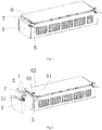
FIG. 1 is a structure diagram of a battery module according to an embodiment of the present invention; -
FIG. 2 is a decomposition diagram of the battery module according to an embodiment of the present invention; -
FIG. 3 is a structure diagram of the battery module, viewed in another direction, according to an embodiment of the present invention; -
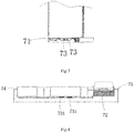
FIG. 4 is a structure diagram of a drainage structure according to an embodiment of the present invention; -
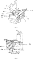
FIG. 5 is a structure diagram of a pole terminal according to an embodiment of the present invention; and -
FIG. 6 is a structure diagram the pole terminal, viewed in another direction, according to an embodiment of the present invention. - To make the objectives, the technical solutions, and the advantages of the present invention clearer, the present invention is further described in detail hereinafter with reference to the accompanying drawings and the embodiments. It should be understood that the specific embodiments described herein are only used for explaining the present invention and are not intended to limit the present invention.
- As shown in
FIG. 1 to FIG. 4 , according to an embodiment of the present invention, a battery module is proposed, which includes acell 1, acover plate 2, anend plate 3, a pole terminal 4, abus bar 5, a connectingmember 6 and adrainage structure 7. - The
cell 1 is arranged on an inner wall of thecover plate 2, theend plate 3 is arranged on an external wall of thecover plate 2, and the pole terminal 4 is arranged on theend plate 3. The pole terminal 4 is provided with a first connecting hole, and thebus bar 5 is provided with a second connectinghole 51. Thedrainage structure 7 is provided with awater storage tank 71. Thewater storage tank 71 is provided at a bottom wall thereof with a first throughhole 72 and a firstwater outlet hole 73, and thedrainage structure 7 is arranged on the external wall of thecover plate 2 and is located above theend plate 3. Theend plate 3 is provided with a secondwater outlet hole 31, the firstwater outlet hole 73 corresponds to the secondwater outlet hole 31 in a vertical direction, and the first throughhole 72 corresponds to the first connecting hole in the vertical direction. The connectingmember 6 sequentially penetrates through the second connectinghole 51 and the first throughhole 72 to be connected to the first connecting hole. - By arranging the
drainage structure 7 on the external wall of thecover plate 2, some water drops on the connectingmember 6 and thebus bar 5 can flow into thewater storage tank 71 of thedrainage structure 7, then flow out of the battery module through the firstwater outlet hole 73 and the secondwater outlet hole 31 of thewater storage tank 71, thus solving a problem of dangerous phenomena such as electric leakage, short circuit, fire and explosion, and the like of the battery module caused by water drops condensed on a nut of a pole and the bus bar which may flow into the battery module. - Both ends of the battery module are provided with the pole terminal 4, and the
drainage structure 7 may be provided at either or both ends of the battery module. That is, the battery module includes a first end and a second end, either the first end or the second end includes thecell 1, thecover plate 2, theend plate 3, the pole terminal 4, thebus bar 5, the connectingmember 6 and thedrainage structure 7, or the first end and the second end both include thecell 1, thecover plate 2, theend plate 3, the pole terminal 4, thebus bar 5, the connectingmember 6 and thedrainage structure 7. - In the embodiment, the connecting
member 6 is ascrew 62 with aplastic gasket 61, and a nut is provided at an upper end of thescrew 62. The water drops are mainly formed on the nut and thebus bar 5. - Since the
drainage structure 7 is located below the connectingmember 6 and thebus bar 5, the water drops formed on the connectingmember 6 andbus bar 5 may fall into thedrainage structure 7. Specifically, the water drops fall into thewater storage tank 71 in thedrainage structure 7, water in thewater storage tank 71 may flow to the firstwater outlet hole 73, and the water in thewater storage tank 71 flows out of thedrainage structure 7 through the firstwater outlet hole 73. Since the firstwater outlet hole 73 corresponds to the secondwater outlet hole 31 in a vertical direction, the water flowing out through the firstwater outlet hole 73 may flow into the secondwater outlet hole 31, and then the water is discharged from the battery module through the secondwater outlet hole 31 to prevent the water from flowing into the battery module. - In order to facilitate flowing of the water in the
water storage tank 71 to the firstwater outlet hole 73, the bottom wall of thewater storage tank 71 is inclined towards the firstwater outlet hole 73. - In some embodiments, two first
water outlet holes 73 are provided, and correspondingly, two secondwater outlet holes 31 are also provided. Each of the firstwater outlet holes 73 corresponds to a respective one of the secondwater outlet holes 31 in a vertical direction. Alternatively, the secondwater outlet hole 31 is a long hole, and the firstwater outlet hole 73 corresponds to the two secondwater outlet holes 31 in a vertical direction. - In the embodiment, the
drainage structure 7 is manufactured using an extrusion molding technology. - In the embodiment, the
drainage structure 7 is adhered to the external wall of thecover plate 2 through a double-sided adhesive tape or glue. Thedrainage structure 7 is located between the pole terminal 4 and thecover plate 2, so as to prevent the condensed water drops on theend plate 3 from having a capillary phenomenon due to a small interval between the inner wall of the pole terminal 4 and thecover plate 2, and prevent the condensed water drops on theend plate 3 from extending upwardly to the connectingmember 6 or thebus bar 5, thus avoiding formation of a continuous waterway from theend plate 3 to the connectingmember 6 or thebus bar 5. - In some embodiments, the
drainage structure 7 and thecover plate 2 are integrally formed. - In the embodiment, the
drainage structure 7 is a plastic member. - In the embodiment, an upper opening of the first
water outlet hole 73 is a water inlet, and a lower opening of the firstwater outlet hole 73 is a water outlet. The water outlet is provided withprotrusions 731 around the water outlet. Theprotrusions 731 have a function of an eave structure, which changes water flowing into water dripping, and prevents the formation of the continuous waterway towards theend plate 3. - In the embodiment, the
drainage structure 7 is provided with a left wrapangle edge structure 74 at a left end thereof that is matched with an upper left angle edge of thecover plate 2, and a right wrapangle edge structure 75 at a right end thereof that is matched with an upper right angle edge of thecover plate 2, thus enabling a more firm fixing on thecover plate 2. Specifically, the left wrapangle edge structure 74 is adhered to the upper left angle edge of thecover plate 2 through the double-sided adhesive tape or glue, and the right wrapangle edge structure 75 is adhered to the upper right angle edge of thecover plate 2 through the double-sided adhesive tape or glue. - As shown in
FIG. 5 andFIG. 4 , in the embodiment, the first connecting hole is arranged in an upper wall of the pole terminal 4, and an upper opening of the first connecting hole is an upper orifice. The upper wall of the pole terminal 4 is provided with awater flowing groove 42 arranged along the upper orifice. The upper wall of the pole terminal 4 is provided with a firstwater guiding groove 43a, and the firstwater guiding groove 43a is communicated with thewater flowing groove 42. The water drops formed on the connectingmember 6 may fall into thewater flowing groove 42, the water flows to the firstwater guiding groove 43a through thewater flowing groove 42, and the firstwater guiding groove 43a discharges the water out of the battery module. - In the embodiment, the upper wall of the pole terminal 4 is provided with a
water returning groove 44 communicated with thewater flowing groove 42, and thewater returning groove 44 tilts upwardly towards thecover plate 2, thus preventing the water from flowing into the battery module, and avoiding condensed water from flowing into the battery module to be communicated with thecell 1. - In the embodiment, an upper surface of an inner wall of the
water returning groove 44 is an inclined surface inclined towards a bottom wall of thewater returning groove 44. The inclined surface structure makes the condensed water drops only be able to flow to thewater flowing groove 42, thus preventing the water from flowing into the battery module, and avoiding the condensed water from flowing into the battery module to be communicated with thecell 1. - In the embodiment, a right wall of the pole terminal 4 is provided with a first opening groove 45a that is opened outwardly, an upper wall of the first opening groove 45a is provided with a
first rib 46a, a right wall of thefirst rib 46a is kept on a same level with the right wall of the pole terminal 4, and the firstwater guiding groove 43a penetrates through the right wall. Thefirst rib 46a has a function of an eave structure, which changes water flowing into water dripping, and prevents the formation of the continuous waterway. The water flows out from the firstwater guiding groove 43a, flows to thefirst rib 46a through the right wall of the pole terminal 4, drips into the first opening groove 45a from thefirst rib 46a, and then flows out through the first opening groove 45a. - In the embodiment, an inner wall of the pole terminal 4 is provided with multiple
water isolation grooves 47, so as to prevent the condensed water drops on theend plate 3 from having a capillary phenomenon due to a small interval between the inner wall of the pole terminal 4 and thecover plate 2, and prevent the condensed water drops on theend plate 3 from extending upwardly to the connectingmember 6 or thebus bar 5, thus avoiding the formation of the continuous waterway from theend plate 3 to the connectingmember 6 or thebus bar 5. - In some embodiments, the upper wall of the pole terminal 4 is provided with a second
water guiding groove 43b communicated with thewater flowing groove 42. The water drops formed on the connectingmember 6 may fall into thewater flowing groove 42, the water flows to the secondwater guiding groove 43b through thewater flowing groove 42, and the secondwater guiding groove 43b discharges the water out of the battery module. - In some embodiments, a left wall of the pole terminal 4 is provided with a
second opening groove 45b that is opened outwardly, an upper wall of thesecond opening groove 45b is provided with asecond rib 46b, a left wall of thesecond rib 46b is kept on a same level with the left wall of the pole terminal 4, and the secondwater guiding groove 43b penetrates through the left wall. Thesecond rib 46b has a function of an eave structure, which changes water flowing into water dripping, and prevents the formation of the continuous waterway. The water flows out from the secondwater guiding groove 43b, flows to thesecond rib 46b through the left wall of the pole terminal 4, drips into thesecond opening groove 45b from thesecond rib 46b, and then flows out through thesecond opening groove 45b. - Those described above are merely preferred embodiments of the present invention, but are not intended to limit the present invention. Any modifications, equivalent substitutions and improvements made without departing from the concept and principle of the present invention shall all fall within the scope of protection of the present invention.
Claims (10)
- A battery module, comprising a cell, a cover plate, an end plate, a pole terminal, a bus bar, a connecting member and a drainage structure, wherein,the cell is arranged on an inner wall of the cover plate, the end plate is arranged on an external wall of the cover plate, the pole terminal is arranged on the end plate,the pole terminal is provided with a first connecting hole, the bus bar is provided with a second connecting hole,the drainage structure is provided with a water storage tank, a bottom wall of the water storage tank is provided with a first through hole and a first water outlet hole, the drainage structure is arranged on the external wall of the cover plate and is located above the end plate,the end plate is provided with a second water outlet hole, the first water outlet hole corresponds to the second water outlet hole in a vertical direction, the first through hole corresponds to the first connecting hole in the vertical direction, and the connecting member is configured to be connected to the first connecting hole by sequentially penetrating through the second connecting hole and the first through hole.
- The battery module according to claim 1, wherein the drainage structure is adhered to the external wall of the cover plate through a double-sided adhesive tape or glue.
- The battery module according to claim 1, wherein the drainage structure is a plastic member.
- The battery module according to claim 1, wherein an upper opening of the first water outlet hole is a water inlet, a lower opening of the first water outlet hole is a water outlet, the water outlet is provided with protrusions around the water outlet.
- The battery module according to claim 1, wherein a left end of the drainage structure is provided with a left wrap angle edge structure matched with an upper left angle edge of the cover plate, and a right end of the drainage structure is provided with a right wrap angle edge structure matched with an upper right angle edge of the cover plate.
- The battery module according to claim 1, wherein the first connecting hole is arranged in an upper wall of the pole terminal, an upper opening of the first connecting hole is an upper orifice, the upper wall of the pole terminal is provided with a water flowing groove along the upper orifice and a first water guiding groove communicated with the water flowing groove.
- The battery module according to claim 6, wherein the upper wall of the pole terminal is provided with a water returning groove communicated with the water flowing groove and tilted upwardly towards the cover plate.
- The battery module according to claim 7, wherein an upper surface of an inner wall of the water returning groove is an inclined surface inclined towards a bottom wall of the water returning groove.
- The battery module according to claim 6, wherein a right wall of the pole terminal is provided with a first opening groove that is opened outwardly, an upper wall of the first opening groove is provided with a first rib, a right wall of the first rib is kept on a same level with the right wall of the pole terminal, and the first water guiding groove penetrates through the right wall.
- The battery module according to claim 6, wherein an inner wall of the pole terminal is provided with a plurality of water isolation grooves.
Applications Claiming Priority (2)
| Application Number | Priority Date | Filing Date | Title |
|---|---|---|---|
| CN202010255522.1A CN111430616B (en) | 2020-04-02 | 2020-04-02 | Battery Module |
| PCT/CN2020/083312 WO2021196210A1 (en) | 2020-04-02 | 2020-04-03 | Battery module |
Publications (4)
| Publication Number | Publication Date |
|---|---|
| EP3910698A1 true EP3910698A1 (en) | 2021-11-17 |
| EP3910698A4 EP3910698A4 (en) | 2022-03-30 |
| EP3910698B1 EP3910698B1 (en) | 2024-03-06 |
| EP3910698C0 EP3910698C0 (en) | 2024-03-06 |
Family
ID=71557412
Family Applications (1)
| Application Number | Title | Priority Date | Filing Date |
|---|---|---|---|
| EP20799597.8A Active EP3910698B1 (en) | 2020-04-02 | 2020-04-03 | Battery module |
Country Status (4)
| Country | Link |
|---|---|
| EP (1) | EP3910698B1 (en) |
| JP (1) | JP7110396B2 (en) |
| CN (1) | CN111430616B (en) |
| WO (1) | WO2021196210A1 (en) |
Families Citing this family (1)
| Publication number | Priority date | Publication date | Assignee | Title |
|---|---|---|---|---|
| WO2025210698A1 (en) * | 2024-04-01 | 2025-10-09 | 日産自動車株式会社 | Battery module |
Family Cites Families (9)
| Publication number | Priority date | Publication date | Assignee | Title |
|---|---|---|---|---|
| JP2001298278A (en) * | 2000-04-12 | 2001-10-26 | Matsushita Electric Ind Co Ltd | Electronics |
| RU2563341C2 (en) * | 2010-11-04 | 2015-09-20 | Макита Корпорейшн | Battery unit |
| JP2012256465A (en) | 2011-06-08 | 2012-12-27 | Honda Motor Co Ltd | Battery module |
| JP5554757B2 (en) * | 2011-07-28 | 2014-07-23 | 矢崎総業株式会社 | Battery pack |
| US10388916B2 (en) * | 2015-09-18 | 2019-08-20 | Gs Yuasa International Ltd. | Energy storage apparatus |
| US10374211B2 (en) * | 2016-09-12 | 2019-08-06 | Cps Technology Holdings Llc | System and method for battery modules having terminal block assemblies with drainage channels |
| JP2019192536A (en) | 2018-04-26 | 2019-10-31 | 株式会社デンソー | Battery module |
| CN208955030U (en) * | 2018-09-30 | 2019-06-07 | 广州市凯捷电源实业有限公司 | A kind of battery cover structure |
| CN211828911U (en) * | 2020-04-02 | 2020-10-30 | 欣旺达电动汽车电池有限公司 | Battery module |
-
2020
- 2020-04-02 CN CN202010255522.1A patent/CN111430616B/en active Active
- 2020-04-03 EP EP20799597.8A patent/EP3910698B1/en active Active
- 2020-04-03 WO PCT/CN2020/083312 patent/WO2021196210A1/en not_active Ceased
- 2020-04-03 JP JP2020563619A patent/JP7110396B2/en active Active
Also Published As
| Publication number | Publication date |
|---|---|
| JP7110396B2 (en) | 2022-08-01 |
| EP3910698A4 (en) | 2022-03-30 |
| EP3910698B1 (en) | 2024-03-06 |
| CN111430616B (en) | 2024-10-15 |
| JP2022530579A (en) | 2022-06-30 |
| CN111430616A (en) | 2020-07-17 |
| WO2021196210A1 (en) | 2021-10-07 |
| EP3910698C0 (en) | 2024-03-06 |
Similar Documents
| Publication | Publication Date | Title |
|---|---|---|
| US10193112B2 (en) | Modular energy storage component enclosure | |
| CN207967074U (en) | Babinet | |
| CN106531953B (en) | Lead-acid accumulator and battery pack | |
| CN215418522U (en) | Top cover assembly and lithium battery | |
| ES2885816T3 (en) | Photovoltaic installation electrical connection device | |
| EP3910698A1 (en) | Battery module | |
| CN110073515B (en) | Battery system of waterproof structure | |
| CN116487773A (en) | Liquid cooling plate, battery box and battery pack | |
| KR102561217B1 (en) | Solar panel-integrated building panel and solar power system including the same | |
| CN211828911U (en) | Battery module | |
| EP4447199A1 (en) | Battery pack | |
| CN215872317U (en) | Controller sealing structure and controller | |
| CN211011764U (en) | Humidifier and waterproof assembly | |
| CN207247713U (en) | Button display module and refrigerating equipment for refrigerating equipment | |
| CN207216997U (en) | A kind of moisture resistance good electronic bulletin screen shell and electronic bulletin screen | |
| CN117073231A (en) | Chassis and integrated air energy water heater | |
| CN212462545U (en) | Roadside electric power cabinet with outdoor warning function | |
| CN223743781U (en) | Battery pack | |
| CN223625123U (en) | Battery cabinet body and power utilization system | |
| CN216016704U (en) | Intelligent security power supply capable of being remotely monitored in real time | |
| CN111555220B (en) | Terminal box | |
| CN222320895U (en) | Cabinet assembly and shared green electric system module | |
| CN223462681U (en) | Wire harness storage device and fan cabinet | |
| CN111769499A (en) | Outdoor bus bridge | |
| CN223360769U (en) | Air conditioning units and air conditioning systems |
Legal Events
| Date | Code | Title | Description |
|---|---|---|---|
| STAA | Information on the status of an ep patent application or granted ep patent |
Free format text: STATUS: UNKNOWN |
|
| STAA | Information on the status of an ep patent application or granted ep patent |
Free format text: STATUS: THE INTERNATIONAL PUBLICATION HAS BEEN MADE |
|
| PUAI | Public reference made under article 153(3) epc to a published international application that has entered the european phase |
Free format text: ORIGINAL CODE: 0009012 |
|
| STAA | Information on the status of an ep patent application or granted ep patent |
Free format text: STATUS: REQUEST FOR EXAMINATION WAS MADE |
|
| 17P | Request for examination filed |
Effective date: 20201109 |
|
| AK | Designated contracting states |
Kind code of ref document: A1 Designated state(s): AL AT BE BG CH CY CZ DE DK EE ES FI FR GB GR HR HU IE IS IT LI LT LU LV MC MK MT NL NO PL PT RO RS SE SI SK SM TR |
|
| RIN1 | Information on inventor provided before grant (corrected) |
Inventor name: HUA, HUANGWEI Inventor name: WANG, TIANFU Inventor name: ZHENG, WEIWEI Inventor name: XI, BINGRONG |
|
| REG | Reference to a national code |
Ref country code: DE Free format text: PREVIOUS MAIN CLASS: H99Z9999999999 Ref country code: DE Ref legal event code: R079 Ref document number: 602020026926 Country of ref document: DE Free format text: PREVIOUS MAIN CLASS: H99Z9999999999 Ipc: H01M0050204000 |
|
| A4 | Supplementary search report drawn up and despatched |
Effective date: 20220225 |
|
| RIC1 | Information provided on ipc code assigned before grant |
Ipc: H01M 50/691 20210101ALI20220222BHEP Ipc: H01M 50/588 20210101ALI20220222BHEP Ipc: H01M 50/296 20210101ALI20220222BHEP Ipc: H01M 50/204 20210101AFI20220222BHEP |
|
| DAV | Request for validation of the european patent (deleted) | ||
| DAX | Request for extension of the european patent (deleted) | ||
| GRAP | Despatch of communication of intention to grant a patent |
Free format text: ORIGINAL CODE: EPIDOSNIGR1 |
|
| STAA | Information on the status of an ep patent application or granted ep patent |
Free format text: STATUS: GRANT OF PATENT IS INTENDED |
|
| RIC1 | Information provided on ipc code assigned before grant |
Ipc: H01M 50/691 20210101ALI20230914BHEP Ipc: H01M 50/588 20210101ALI20230914BHEP Ipc: H01M 50/296 20210101ALI20230914BHEP Ipc: H01M 50/204 20210101AFI20230914BHEP |
|
| INTG | Intention to grant announced |
Effective date: 20231009 |
|
| RAP3 | Party data changed (applicant data changed or rights of an application transferred) |
Owner name: SUNWODA MOBILITY ENERGY TECHNOLOGY CO., LTD. |
|
| GRAS | Grant fee paid |
Free format text: ORIGINAL CODE: EPIDOSNIGR3 |
|
| GRAA | (expected) grant |
Free format text: ORIGINAL CODE: 0009210 |
|
| STAA | Information on the status of an ep patent application or granted ep patent |
Free format text: STATUS: THE PATENT HAS BEEN GRANTED |
|
| AK | Designated contracting states |
Kind code of ref document: B1 Designated state(s): AL AT BE BG CH CY CZ DE DK EE ES FI FR GB GR HR HU IE IS IT LI LT LU LV MC MK MT NL NO PL PT RO RS SE SI SK SM TR |
|
| REG | Reference to a national code |
Ref country code: CH Ref legal event code: EP |
|
| REG | Reference to a national code |
Ref country code: IE Ref legal event code: FG4D |
|
| REG | Reference to a national code |
Ref country code: DE Ref legal event code: R096 Ref document number: 602020026926 Country of ref document: DE |
|
| U01 | Request for unitary effect filed |
Effective date: 20240321 |
|
| U07 | Unitary effect registered |
Designated state(s): AT BE BG DE DK EE FI FR IT LT LU LV MT NL PT SE SI Effective date: 20240403 |
|
| U20 | Renewal fee for the european patent with unitary effect paid |
Year of fee payment: 5 Effective date: 20240402 |
|
| PG25 | Lapsed in a contracting state [announced via postgrant information from national office to epo] |
Ref country code: GR Free format text: LAPSE BECAUSE OF FAILURE TO SUBMIT A TRANSLATION OF THE DESCRIPTION OR TO PAY THE FEE WITHIN THE PRESCRIBED TIME-LIMIT Effective date: 20240607 |
|
| PG25 | Lapsed in a contracting state [announced via postgrant information from national office to epo] |
Ref country code: HR Free format text: LAPSE BECAUSE OF FAILURE TO SUBMIT A TRANSLATION OF THE DESCRIPTION OR TO PAY THE FEE WITHIN THE PRESCRIBED TIME-LIMIT Effective date: 20240306 Ref country code: RS Free format text: LAPSE BECAUSE OF FAILURE TO SUBMIT A TRANSLATION OF THE DESCRIPTION OR TO PAY THE FEE WITHIN THE PRESCRIBED TIME-LIMIT Effective date: 20240606 |
|
| PG25 | Lapsed in a contracting state [announced via postgrant information from national office to epo] |
Ref country code: ES Free format text: LAPSE BECAUSE OF FAILURE TO SUBMIT A TRANSLATION OF THE DESCRIPTION OR TO PAY THE FEE WITHIN THE PRESCRIBED TIME-LIMIT Effective date: 20240306 |
|
| PG25 | Lapsed in a contracting state [announced via postgrant information from national office to epo] |
Ref country code: RS Free format text: LAPSE BECAUSE OF FAILURE TO SUBMIT A TRANSLATION OF THE DESCRIPTION OR TO PAY THE FEE WITHIN THE PRESCRIBED TIME-LIMIT Effective date: 20240606 Ref country code: NO Free format text: LAPSE BECAUSE OF FAILURE TO SUBMIT A TRANSLATION OF THE DESCRIPTION OR TO PAY THE FEE WITHIN THE PRESCRIBED TIME-LIMIT Effective date: 20240606 Ref country code: HR Free format text: LAPSE BECAUSE OF FAILURE TO SUBMIT A TRANSLATION OF THE DESCRIPTION OR TO PAY THE FEE WITHIN THE PRESCRIBED TIME-LIMIT Effective date: 20240306 Ref country code: GR Free format text: LAPSE BECAUSE OF FAILURE TO SUBMIT A TRANSLATION OF THE DESCRIPTION OR TO PAY THE FEE WITHIN THE PRESCRIBED TIME-LIMIT Effective date: 20240607 Ref country code: ES Free format text: LAPSE BECAUSE OF FAILURE TO SUBMIT A TRANSLATION OF THE DESCRIPTION OR TO PAY THE FEE WITHIN THE PRESCRIBED TIME-LIMIT Effective date: 20240306 |
|
| PG25 | Lapsed in a contracting state [announced via postgrant information from national office to epo] |
Ref country code: IS Free format text: LAPSE BECAUSE OF FAILURE TO SUBMIT A TRANSLATION OF THE DESCRIPTION OR TO PAY THE FEE WITHIN THE PRESCRIBED TIME-LIMIT Effective date: 20240706 |
|
| PG25 | Lapsed in a contracting state [announced via postgrant information from national office to epo] |
Ref country code: SM Free format text: LAPSE BECAUSE OF FAILURE TO SUBMIT A TRANSLATION OF THE DESCRIPTION OR TO PAY THE FEE WITHIN THE PRESCRIBED TIME-LIMIT Effective date: 20240306 |
|
| PG25 | Lapsed in a contracting state [announced via postgrant information from national office to epo] |
Ref country code: CZ Free format text: LAPSE BECAUSE OF FAILURE TO SUBMIT A TRANSLATION OF THE DESCRIPTION OR TO PAY THE FEE WITHIN THE PRESCRIBED TIME-LIMIT Effective date: 20240306 |
|
| PG25 | Lapsed in a contracting state [announced via postgrant information from national office to epo] |
Ref country code: PL Free format text: LAPSE BECAUSE OF FAILURE TO SUBMIT A TRANSLATION OF THE DESCRIPTION OR TO PAY THE FEE WITHIN THE PRESCRIBED TIME-LIMIT Effective date: 20240306 |
|
| PG25 | Lapsed in a contracting state [announced via postgrant information from national office to epo] |
Ref country code: SK Free format text: LAPSE BECAUSE OF FAILURE TO SUBMIT A TRANSLATION OF THE DESCRIPTION OR TO PAY THE FEE WITHIN THE PRESCRIBED TIME-LIMIT Effective date: 20240306 |
|
| PG25 | Lapsed in a contracting state [announced via postgrant information from national office to epo] |
Ref country code: SM Free format text: LAPSE BECAUSE OF FAILURE TO SUBMIT A TRANSLATION OF THE DESCRIPTION OR TO PAY THE FEE WITHIN THE PRESCRIBED TIME-LIMIT Effective date: 20240306 Ref country code: SK Free format text: LAPSE BECAUSE OF FAILURE TO SUBMIT A TRANSLATION OF THE DESCRIPTION OR TO PAY THE FEE WITHIN THE PRESCRIBED TIME-LIMIT Effective date: 20240306 Ref country code: RO Free format text: LAPSE BECAUSE OF FAILURE TO SUBMIT A TRANSLATION OF THE DESCRIPTION OR TO PAY THE FEE WITHIN THE PRESCRIBED TIME-LIMIT Effective date: 20240306 Ref country code: PL Free format text: LAPSE BECAUSE OF FAILURE TO SUBMIT A TRANSLATION OF THE DESCRIPTION OR TO PAY THE FEE WITHIN THE PRESCRIBED TIME-LIMIT Effective date: 20240306 Ref country code: IS Free format text: LAPSE BECAUSE OF FAILURE TO SUBMIT A TRANSLATION OF THE DESCRIPTION OR TO PAY THE FEE WITHIN THE PRESCRIBED TIME-LIMIT Effective date: 20240706 Ref country code: CZ Free format text: LAPSE BECAUSE OF FAILURE TO SUBMIT A TRANSLATION OF THE DESCRIPTION OR TO PAY THE FEE WITHIN THE PRESCRIBED TIME-LIMIT Effective date: 20240306 |
|
| REG | Reference to a national code |
Ref country code: CH Ref legal event code: PL |
|
| REG | Reference to a national code |
Ref country code: DE Ref legal event code: R097 Ref document number: 602020026926 Country of ref document: DE |
|
| PG25 | Lapsed in a contracting state [announced via postgrant information from national office to epo] |
Ref country code: MC Free format text: LAPSE BECAUSE OF FAILURE TO SUBMIT A TRANSLATION OF THE DESCRIPTION OR TO PAY THE FEE WITHIN THE PRESCRIBED TIME-LIMIT Effective date: 20240306 |
|
| PLBE | No opposition filed within time limit |
Free format text: ORIGINAL CODE: 0009261 |
|
| STAA | Information on the status of an ep patent application or granted ep patent |
Free format text: STATUS: NO OPPOSITION FILED WITHIN TIME LIMIT |
|
| PG25 | Lapsed in a contracting state [announced via postgrant information from national office to epo] |
Ref country code: MC Free format text: LAPSE BECAUSE OF FAILURE TO SUBMIT A TRANSLATION OF THE DESCRIPTION OR TO PAY THE FEE WITHIN THE PRESCRIBED TIME-LIMIT Effective date: 20240306 Ref country code: CH Free format text: LAPSE BECAUSE OF NON-PAYMENT OF DUE FEES Effective date: 20240430 |
|
| 26N | No opposition filed |
Effective date: 20241209 |
|
| U20 | Renewal fee for the european patent with unitary effect paid |
Year of fee payment: 6 Effective date: 20250310 |
|
| PG25 | Lapsed in a contracting state [announced via postgrant information from national office to epo] |
Ref country code: IE Free format text: LAPSE BECAUSE OF NON-PAYMENT OF DUE FEES Effective date: 20240403 |
|
| PG25 | Lapsed in a contracting state [announced via postgrant information from national office to epo] |
Ref country code: CY Free format text: LAPSE BECAUSE OF FAILURE TO SUBMIT A TRANSLATION OF THE DESCRIPTION OR TO PAY THE FEE WITHIN THE PRESCRIBED TIME-LIMIT; INVALID AB INITIO Effective date: 20200403 |
|
| PG25 | Lapsed in a contracting state [announced via postgrant information from national office to epo] |
Ref country code: HU Free format text: LAPSE BECAUSE OF FAILURE TO SUBMIT A TRANSLATION OF THE DESCRIPTION OR TO PAY THE FEE WITHIN THE PRESCRIBED TIME-LIMIT; INVALID AB INITIO Effective date: 20200403 |
|
| PG25 | Lapsed in a contracting state [announced via postgrant information from national office to epo] |
Ref country code: TR Free format text: LAPSE BECAUSE OF FAILURE TO SUBMIT A TRANSLATION OF THE DESCRIPTION OR TO PAY THE FEE WITHIN THE PRESCRIBED TIME-LIMIT Effective date: 20240306 |
|
| PGFP | Annual fee paid to national office [announced via postgrant information from national office to epo] |
Ref country code: GB Payment date: 20260223 Year of fee payment: 7 |
|
| U20 | Renewal fee for the european patent with unitary effect paid |
Year of fee payment: 7 Effective date: 20260310 |