EP3910661B1 - Thermal cutoff - Google Patents
Thermal cutoff Download PDFInfo
- Publication number
- EP3910661B1 EP3910661B1 EP19920100.5A EP19920100A EP3910661B1 EP 3910661 B1 EP3910661 B1 EP 3910661B1 EP 19920100 A EP19920100 A EP 19920100A EP 3910661 B1 EP3910661 B1 EP 3910661B1
- Authority
- EP
- European Patent Office
- Prior art keywords
- fusible element
- partition plate
- cavity
- plate
- fuse link
- Prior art date
- Legal status (The legal status is an assumption and is not a legal conclusion. Google has not performed a legal analysis and makes no representation as to the accuracy of the status listed.)
- Active
Links
Images
Classifications
-
- H—ELECTRICITY
- H01—ELECTRIC ELEMENTS
- H01H—ELECTRIC SWITCHES; RELAYS; SELECTORS; EMERGENCY PROTECTIVE DEVICES
- H01H85/00—Protective devices in which the current flows through a part of fusible material and this current is interrupted by displacement of the fusible material when this current becomes excessive
- H01H85/02—Details
- H01H85/04—Fuses, i.e. expendable parts of the protective device, e.g. cartridges
- H01H85/05—Component parts thereof
- H01H85/055—Fusible members
- H01H85/06—Fusible members characterised by the fusible material
-
- H—ELECTRICITY
- H01—ELECTRIC ELEMENTS
- H01H—ELECTRIC SWITCHES; RELAYS; SELECTORS; EMERGENCY PROTECTIVE DEVICES
- H01H37/00—Thermally-actuated switches
- H01H37/74—Switches in which only the opening movement or only the closing movement of a contact is effected by heating or cooling
- H01H37/76—Contact member actuated by melting of fusible material, actuated due to burning of combustible material or due to explosion of explosive material
- H01H37/761—Contact member actuated by melting of fusible material, actuated due to burning of combustible material or due to explosion of explosive material with a fusible element forming part of the switched circuit
-
- H—ELECTRICITY
- H01—ELECTRIC ELEMENTS
- H01H—ELECTRIC SWITCHES; RELAYS; SELECTORS; EMERGENCY PROTECTIVE DEVICES
- H01H85/00—Protective devices in which the current flows through a part of fusible material and this current is interrupted by displacement of the fusible material when this current becomes excessive
- H01H85/02—Details
- H01H85/04—Fuses, i.e. expendable parts of the protective device, e.g. cartridges
- H01H85/05—Component parts thereof
- H01H85/055—Fusible members
- H01H85/12—Two or more separate fusible members in parallel
-
- H—ELECTRICITY
- H01—ELECTRIC ELEMENTS
- H01H—ELECTRIC SWITCHES; RELAYS; SELECTORS; EMERGENCY PROTECTIVE DEVICES
- H01H85/00—Protective devices in which the current flows through a part of fusible material and this current is interrupted by displacement of the fusible material when this current becomes excessive
- H01H85/02—Details
- H01H85/04—Fuses, i.e. expendable parts of the protective device, e.g. cartridges
- H01H85/05—Component parts thereof
- H01H85/143—Electrical contacts; Fastening fusible members to such contacts
-
- H—ELECTRICITY
- H01—ELECTRIC ELEMENTS
- H01H—ELECTRIC SWITCHES; RELAYS; SELECTORS; EMERGENCY PROTECTIVE DEVICES
- H01H85/00—Protective devices in which the current flows through a part of fusible material and this current is interrupted by displacement of the fusible material when this current becomes excessive
- H01H85/02—Details
- H01H85/04—Fuses, i.e. expendable parts of the protective device, e.g. cartridges
- H01H85/05—Component parts thereof
- H01H85/165—Casings
- H01H85/175—Casings characterised by the casing shape or form
-
- H—ELECTRICITY
- H01—ELECTRIC ELEMENTS
- H01H—ELECTRIC SWITCHES; RELAYS; SELECTORS; EMERGENCY PROTECTIVE DEVICES
- H01H85/00—Protective devices in which the current flows through a part of fusible material and this current is interrupted by displacement of the fusible material when this current becomes excessive
- H01H85/02—Details
- H01H85/38—Means for extinguishing or suppressing arc
-
- H—ELECTRICITY
- H01—ELECTRIC ELEMENTS
- H01H—ELECTRIC SWITCHES; RELAYS; SELECTORS; EMERGENCY PROTECTIVE DEVICES
- H01H85/00—Protective devices in which the current flows through a part of fusible material and this current is interrupted by displacement of the fusible material when this current becomes excessive
- H01H85/02—Details
- H01H85/38—Means for extinguishing or suppressing arc
- H01H2085/381—Means for extinguishing or suppressing arc with insulating body insertable between the end contacts of the fusible element
-
- H—ELECTRICITY
- H01—ELECTRIC ELEMENTS
- H01H—ELECTRIC SWITCHES; RELAYS; SELECTORS; EMERGENCY PROTECTIVE DEVICES
- H01H85/00—Protective devices in which the current flows through a part of fusible material and this current is interrupted by displacement of the fusible material when this current becomes excessive
- H01H85/02—Details
- H01H85/04—Fuses, i.e. expendable parts of the protective device, e.g. cartridges
- H01H85/041—Fuses, i.e. expendable parts of the protective device, e.g. cartridges characterised by the type
- H01H85/042—General constructions or structure of high voltage fuses, i.e. above 1000 V
-
- H—ELECTRICITY
- H01—ELECTRIC ELEMENTS
- H01H—ELECTRIC SWITCHES; RELAYS; SELECTORS; EMERGENCY PROTECTIVE DEVICES
- H01H85/00—Protective devices in which the current flows through a part of fusible material and this current is interrupted by displacement of the fusible material when this current becomes excessive
- H01H85/02—Details
- H01H85/04—Fuses, i.e. expendable parts of the protective device, e.g. cartridges
- H01H85/05—Component parts thereof
- H01H85/055—Fusible members
- H01H85/08—Fusible members characterised by the shape or form of the fusible member
-
- H—ELECTRICITY
- H01—ELECTRIC ELEMENTS
- H01H—ELECTRIC SWITCHES; RELAYS; SELECTORS; EMERGENCY PROTECTIVE DEVICES
- H01H85/00—Protective devices in which the current flows through a part of fusible material and this current is interrupted by displacement of the fusible material when this current becomes excessive
- H01H85/02—Details
- H01H85/04—Fuses, i.e. expendable parts of the protective device, e.g. cartridges
- H01H85/05—Component parts thereof
- H01H85/18—Casing fillings, e.g. powder
-
- Y—GENERAL TAGGING OF NEW TECHNOLOGICAL DEVELOPMENTS; GENERAL TAGGING OF CROSS-SECTIONAL TECHNOLOGIES SPANNING OVER SEVERAL SECTIONS OF THE IPC; TECHNICAL SUBJECTS COVERED BY FORMER USPC CROSS-REFERENCE ART COLLECTIONS [XRACs] AND DIGESTS
- Y02—TECHNOLOGIES OR APPLICATIONS FOR MITIGATION OR ADAPTATION AGAINST CLIMATE CHANGE
- Y02E—REDUCTION OF GREENHOUSE GAS [GHG] EMISSIONS, RELATED TO ENERGY GENERATION, TRANSMISSION OR DISTRIBUTION
- Y02E60/00—Enabling technologies; Technologies with a potential or indirect contribution to GHG emissions mitigation
- Y02E60/10—Energy storage using batteries
Definitions
- the present invention relates to a fusible thermal cutoff, and in particular, to a high-voltage thermal cutoff.
- High-voltage thermal cutoffs have numerous applications. They are used, for example, as circuit protection devices in heating systems in electric vehicles.
- two fuse links (where the two fuse links are both fusible alloys, or one of them is a fusible alloy and the other is an alloy wire) are arranged side by side horizontally.
- Applicant previously proposed thermal cutoffs as disclosed in Chinese patent No. CN208093500U and No. CN206976273U , in which two fuse links are arranged side by side horizontally at the welding ends of two electrode plates.
- the high-voltage thermal cutoff with such a configuration has advantages in manufacture, in its entirety, the high-voltage thermal cutoff is shaped like a large block or a flat sheet, and thus cannot be effectively used in many applications due to limitations caused by its shape.
- the space left for the thermal cutoff is relatively small.
- the prior parallel configuration is not suitable for positions with higher space requirements on compactness.
- CN101859665A discloses an alloy type thermal fuse with high amperage capacity, which can protect the overheating of devices with high current characteristics such as power batteries.
- US5373278A discloses a blade type plug-in fuse for nominal currents in excess of or equal to 20 amperes, and more particularly an automobile blade type plug-in fuses.
- US2003001716A1 discloses a fuse with two spaced-apart power supply connections and with an active part comprising a fusible, current-carrying fuse element and an arc-extinguishing medium, in which the fuse element is of a modular construction, has at least two first modules connected in series and is connected in an electrically conducting manner to the two power supply connections and is arranged on an electrically insulating substrate, and in which the arc-extinguishing medium covers the exposed surfaces of the fuse element, wherein the active part is formed in the manner of a sandwich and has two stable moldings and a predominantly planar intermediate layer arranged between the two moldings, the intermediate layer containing at least the two series-connected first modules, whereas a first molding of the two moldings is formed at least by part of the electrically insulating substrate and the second molding is formed
- CN205900482U discloses a laminated type temperature protection device, comprising a casing, a cover plate, an upper electrode sheet, a lower electrode sheet, at least two low-melting alloy wires, a fusing agent, an epoxy resin, the upper electrode sheet, the lower electrode sheet. At least two low-melting alloy wires and a fusing agent are located in the cavity enclosed by the casing and the cover plate and sealed by epoxy resin, the at least two low-melting alloy wires are connected in parallel between the upper and lower electrode sheets. The lead-out ends of the upper and lower electrode sheets are respectively led out from the cavity through the openings on both sides of the casing.
- a separation device including a compartment frame and a blocking plate is also arranged between the upper and lower electrode sheets, and the separation device separates the cavity, the upper and lower electrodes.
- the space between the sheets is divided into a plurality of independent chambers, wherein each chamber accommodates a low melting point alloy wire and a flux that wraps the low melting point alloy wire.
- the present invention provides a thermal cutoff with an improved configuration.
- a thermal cutoff having elongated shape with a vertical configuration including a first fusible element, a second fusible element, and a closed cavity bounded by a housing having an open end, a cover plate and a sealant.
- the two ends of the first fusible element and the two ends of the second fusible element are connected in parallel to a first electrode and a second electrode, respectively.
- the first fusible element and the second fusible element are provided in the closed cavity.
- a direction extending from a closed end to the open end of the housing is defined as a vertical direction.
- the first fusible element and the second fusible element are vertically arranged relatively to each other.
- the cover plate is inserted and fitted in the closed cavity to divide the closed cavity into a first cavity and a second cavity, wherein the first cavity and the second cavity are arranged relatively to each other in the vertical direction; and the first fusible element and second fusible element are arranged in the first cavity and the second cavity, respectively.
- the first fusible element is a current-carrying fusible element
- the second fusible element is a high-voltage fusible element.
- the current-carrying fusible element comprises a current carrier
- the high-voltage fusible element comprises a U-shaped fuse link with parallel segments at two ends.
- a melting point of the current carrier is lower than a melting point of the fuse link, and an internal resistance value of the current carrier is lower than an internal resistance value of the fuse link.
- the cover plate comprises a bottom plate, a first partition plate, a second partition plate, and a third partition plate.
- the bottom plate is located at a lower end of the cover plate.
- the first partition plate, the second partition plate, and the third partition plate are perpendicular to the bottom plate.
- the first partition plate and the second partition plate are arranged in parallel at intervals.
- the third partition plate is perpendicular to both the first partition plate and the second partition plate.
- the third partition plate separates parallel segments of the fuse link from each other.
- the first partition plate and the second partition plate are configured for separating two outer sides of the fuse link, respectively.
- the present invention implements a thermal cutoff with a vertical configuration, so that the thermal cutoff in its entirety has an elongated shape to meet corresponding application requirements.
- the present invention provides a thermal cutoff with an improved configuration as follows.
- a first fusible element and a second fusible element connected in parallel are provided as core functional devices in a closed cavity bounded by the housing 101, the cover plate 102, and the sealant 103.
- the housing 101 has the first cavity (current-carrying fusing cavity) 101a and the second cavity (high-voltage fusing cavity) 101b corresponding to a current-carrying fusible element and a high-voltage fusible element, respectively.
- the cover plate 102 is inserted into and fitted in an inner cavity of the housing 101 to divide the inner cavity into the first cavity 101a and the second cavity 101b.
- a direction extending from a closed end to an open end of the housing 101 is defined as a vertical direction.
- the second cavity 101b and the first cavity 101a in the present embodiment are vertically arranged relatively to each other (as shown in the figure).
- the housing 101 in a roughly rectangular shape connected to a semicircular piece is used as an example for description, while the cover plate 102 and the sealant 103 adapted to the housing 101 also have matching shapes, but the shapes of the housing 101, the cover plate 102 and the sealant 103 in the present embodiment should not be limited thereto.
- the housing 101 is preferably in an elongated shape, such as a cylinder or a hexagonal prism.
- the direction extending along the length of the housing 101 in an elongated shape is defined as the vertical direction.
- the cover plate 102 is inserted into and matches the inner cavity of the housing 101 (where a gap between the cover plate 102 and the housing 101 is also sealed by a small amount of sealant), and is located above the sealant 103 at the lower end, so that the inner cavity of the housing 101 is divided and partitioned into the second cavity 101b and the first cavity 101a arranged vertically relatively to each other.
- the housing 101, the cover plate 102 and the sealant 103 are all made of materials with excellent insulation properties.
- the housing 101 and the cover plate 102 are made of ceramic, and the sealant 103 is made of epoxy resin.
- the mounting hole 101c is provided on the semicircular piece of the housing 101, and the mounting hole 101c is configured for mounting and fixing to a protected device.
- the first fusible element and the second fusible element serving as the core functional devices are described by taking a current-carrying fusible element and a high-voltage fusible element connected in parallel as an example.
- the current-carrying fusible element and the high-voltage fusible element are shown as the U-shaped fuse link 106 and the straight current carrier 104 arranged vertically relatively to each other.
- the melting point of the current carrier 104 is lower than the melting point of the fuse link 106
- the internal resistance value of the current carrier 104 is lower than the internal resistance value of the fuse link 106. Both ends of the U-shaped fuse link 106 have parallel segments.
- the current carrier 104 is made of a fusible alloy.
- the fusible alloy generally refers to metal with a melting point of lower than 300°C and alloys thereof.
- the fusible alloy is made of Bi, Sn, Pb, In and other metal elements with low melting points.
- the fuse link 106 also adopts an electrothermal heating element with a higher fusing temperature serving as a fusible element, such as a silver-copper alloy, a fusible alloy, a constantan wire, a Fe-Cr-Al heating element, or a nickel-chromium wire.
- a fusible element such as a silver-copper alloy, a fusible alloy, a constantan wire, a Fe-Cr-Al heating element, or a nickel-chromium wire.
- the first cavity 101a and the second cavity 101b are filled with the fusing agent 105 and the arc extinguishing medium 107, respectively.
- the fusing agent 105 contacts and wraps the current carrier 104 provided in the first cavity 101a, while the arc extinguishing medium 107 contacts and wraps the fuse link 106 provided in the second cavity 101b.
- the fusing agent 105 is selected from substances capable of reducing the surface tension of an alloy to be fused, for example, a solder paste made of rosin substances (natural rosin, synthetic rosin, and the like).
- the arc extinguishing medium 107 is selected from an arc extinguishing paste, quartz sand, sulfur hexafluoride, transformer oil, and the like.
- the current mainly flows through the current carrier 104.
- the temperature is transferred to the current carrier 104.
- the current carrier 104 shrinks and breaks under the effect of the tension of the fusing agent 105, thereby breaking the parallel branch where the current carrier 104 is located.
- the fuse link 106 At the moment when the current carrier 104 fuses due to over-temperature, as the melting point of the fuse link 106 is higher than the melting point of the current carrier 104, the fuse link 106 still maintains a conducting state, and the current is all loaded on the fuse link 106, making the fuse link 106 generate heat. Under a combined action of the increasing heat and the rising temperature, the fuse link 106 reaches its melting point, and then the fuse link 106 shrinks rapidly and fuses itself. An arc is inevitably generated during the breaking process.
- the second cavity 101b is filled with the arc extinguishing medium 107 for extinguishing the arc, thereby protecting the safety of the circuit.
- the fuse link in the present embodiment in some application scenarios is also a fusible alloy made of Bi, Sn, Pb, In and other metal elements with low melting points, provided that the fuse link meets the following requirements by adjusting ratios of the elements: the melting point of the fuse link is higher than the melting point of the current carrier, and the internal resistance value of the fuse link is higher than the internal resistance value of the current carrier.
- the arc extinguishing medium filled in the second cavity of the present embodiment is replaced with a fusing agent.
- the electrode for connecting the current carrier 104 to the fuse link 106 includes the first electrode plate 108 and the second electrode plate 109.
- the first electrode plate 108 and the second electrode plate 109 are of the same shape and are mirror-symmetric to facilitate mass production.
- Each of the first electrode plate 108 and the second electrode plate 109 is a roughly straight structure formed by stamping a conductive metal sheet.
- One end 108a (the upper end in the figure) of the straight first electrode plate 108 and one end 109a (the upper end in the figure) of the second electrode plate 109 are bent to form small L-shaped segments, which form a welding table to be connected to the two ends of the U-shaped fuse link 106, respectively.
- Opposite sides (inner sides) at the middle positions of the first electrode plate 108 and the second electrode plate 109 are connected to the two ends of the straight current carrier 104, respectively, to form an electrical parallel structure of the fuse link 106 and the current carrier 104 arranged vertically relatively to each other, corresponding to the second cavity 101b and the first cavity 101a arranged vertically relatively to each other, respectively.
- the cover plate 102 includes the bottom plate 102e located at its lower end as well as the first partition plate 102c, the second partition plate 102d and the third partition plate 102f that are perpendicular to the bottom plate 102e.
- the first partition plate 102c and the second partition plate 102d are arranged in parallel at intervals, and the third partition plate 102f is perpendicular to both the first partition plate 102c and the second partition plate 102d.
- the third partition plate 102f separates the parallel segments of the U-shaped fuse link 106, while the first partition plate 102c and the second partition plate 102d are configured to separate the two outer sides of the fuse link 106, respectively.
- the first electrode plate 108 and the second electrode plate 109 are provided with the clamping notches 108b, 109b between the current carrier 104 and the fuse link 106 arranged vertically. Both sides of the bottom plate 102e of the cover plate 102 are provided with clamping grooves corresponding to the clamping notches 108b, 109b of the first electrode plate 108 and the second electrode plate 109, so that the cover plate 102 vertically separates the current carrier 104 and the fuse link 106 relatively to each other.
- each of the first partition plate 102c, the second partition plate 102d, and the third partition plate 102f have the undulating profiles 102b, 102a, which, for example, are concave-shaped undulating profiles as shown in the figure of the present embodiment.
- a top inner wall of the housing in the present embodiment is further provided with ridges or protrusions (not shown in the figure) to increase the creepage distance.
- the other end (the lower end in the figure) of the first electrode plate 108 is welded to the first lead wire 112, and the other end (the lower end in the figure) of the second electrode plate 109 is welded to the second lead wire 113, so as to form an electrical connection between the first lead wire 112, the first electrode plate 108, the current carrier 104, the fuse link 106, the second electrode plate 109, and the second lead wire 113.
- the first lead wire 112 and the second lead wire 113 are welded to the inner sides of the first electrode plate 108 and the second electrode plate 109, respectively, and extend vertically downward.
- the welding between the first lead wire 112 and the first electrode plate 108 as well as the welding between the second electrode plate 109 and the second lead wire 113 are implemented by spot welding using tin solder, ultrasonic metal welding, or the like.
- the first lead wire 112 and the second lead wire 113 are both multi-stranded wires, such as copper stranded wires, and thus can be bent more flexibly.
- Each of the first lead wire 112 and the second lead wire 113 is wrapped by an insulating sheath.
- the material of the insulating sheath is selected from Teflon, silicone rubber, a polyester material and other insulators with excellent insulation properties.
- the sealant 103 needs to meet filling requirements as follows: the sealant 103 at least covers the weld between the first lead wire 112 and the first electrode plate 108 and an end of the first lead wire 112, and also covers the weld between the second electrode plate 109 and the second lead wire 113 and an end of the second lead wire 113.
- the first lead wire 112 and the second lead wire 113 are led out from the same end and extend downward to form a package structure with a radial configuration.
- the package structure with the radial configuration is more suitable for the main circuit of the PTC heater than a package structure with axial configuration in the prior art, and does not need to fold back the wire harness at one end, which facilitates the mounting operation.
- the electrode plates are welded to the lead wires before being led out, and the welds and the ends of the lead wires are sealed with a sealant, so as to achieve an excellent sealing protection effect, which is in line with the requirements for use in the field of waterproofing.
- Embodiment 1 it is also feasible to replace the package structure with the radial configuration in Embodiment 1 by a package structure with an axial configuration similar to that in Chinese patent Nos. CN208093500U and CN206976273U in the prior art.
- the thermal cutoff in the present embodiment is longer and slimmer than the existing thermal cutoff with a parallel horizontal configuration, and is thus applicable to some occasions with specific needs.
- the thermal cutoff in a heater of a liquid cooling system due to the arrangement of the circuit board and other control parts, the space left for the thermal cutoff is relatively small.
- the prior parallel configuration is not suitable for positions with higher space requirements on compactness, and the thermal cutoff of the present embodiment can be used instead to meet such application requirements.
- Embodiment 1 adopts a sealed structural design to achieve an excellent sealing protection effect, which is in line with the requirements for use in the field of waterproofing.
- the current-carrying fusible element and the high-voltage fusible element are spaced apart, and the fuse link serving as the high-voltage fusible element is made of a material with higher voltage withstand capability and is filled with the arc extinguishing medium, so as to withstand a higher voltage level.
- the present embodiment adopts an elongated shape design while having a range of high-voltage applications, and is applicable to scenarios where the operating voltage is lower than 850-1000 VDC.
- the thermal cutoff of Embodiment 2 is similar to that of Embodiment 1.
- a current-carrying fusible element and a high-voltage fusible element connected in parallel are provided as core functional devices in a closed cavity bounded by the housing 201, the cover plate 202, and the sealant 203.
- the housing 201 has the first cavity (current-carrying fusing cavity) 201a and the second cavity (high-voltage fusing cavity) 201b corresponding to the current-carrying fusible element and the high-voltage fusible element, respectively.
- the cover plate 202 is inserted into and fitted in an inner cavity of the housing 201 to divide the inner cavity into the first cavity 201a and the second cavity 201b arranged vertically relatively to each other.
- the current-carrying fusible element and the high-voltage fusible element connected in parallel are shown as the U-shaped fuse link 206 and the straight current carrier 204 arranged vertically relatively to each other.
- the melting point of the current carrier 204 is lower than the melting point of the fuse link 206, and the internal resistance value of the current carrier 204 is lower than the internal resistance value of the fuse link 206.
- the first cavity 201a and the second cavity 201b are filled with the fusing agent 205 and the arc extinguishing medium 207 (which is alternatively a fusing agent depending on the material of the fuse link), respectively.
- the fusing agent 205 contacts and wraps the current carrier 204 provided in the first cavity 201a, while the arc extinguishing medium 207 contacts and wraps the fuse link 206 provided in the second cavity 201b.
- the difference between Embodiment 2 and Embodiment 1 is as follows.
- the first electrode plate 208 and the second electrode plate 209 for connecting the current carrier 204 to the fuse link 206 are roughly straight identical sheet structures that are mirror-symmetric and formed by stamping conductive metal sheets.
- the upper ends of the first electrode plate 208 and the second electrode plate 209 are not bent into a welding table similar to that in Embodiment 1, and the U-shaped fuse link 206 is directly welded to the upper ends thereof.
- the first electrode plate 208 and the second electrode plate 209 are less convenient to weld compared with Embodiment 1, but the stamping process of the electrode plate is simpler in manufacture and thus has certain cost advantages.
- the other end (the lower end in the figure) of the first electrode plate 208 is welded to the first lead wire 212 on the outer side
- the other end (the lower end in the figure) of the second electrode plate 209 is welded to the second lead wire 213 on the outer side.
- the welding operation in the present embodiment is simpler and more convenient while achieving the same sealing protection effect.
- the thermal cutoff of Embodiment 3 is similar to that of Embodiment 1.
- a current-carrying fusible element and a high-voltage fusible element connected in parallel are provided as core functional devices in a closed cavity bounded by the housing 301, the cover plate 302, and the sealant 303.
- the housing 301 has the first cavity (current-carrying fusing cavity) 301a and the second cavity (high-voltage fusing cavity) 301b corresponding to the current-carrying fusible element and the high-voltage fusible element, respectively.
- the cover plate 302 is inserted into and fitted in an inner cavity of the housing 301 to divide the inner cavity into the first cavity 301a and the second cavity 301b arranged vertically relatively to each other.
- the current-carrying fusible element and the high-voltage fusible element connected in parallel are shown as the U-shaped fuse link 306 and the straight current carrier 304 arranged vertically relatively to each other.
- the melting point of the current carrier 304 is lower than the melting point of the fuse link 306, and the internal resistance value of the current carrier 304 is lower than the internal resistance value of the fuse link 306.
- the first cavity 301a and the second cavity 301b are filled with the fusing agent 305 and the arc extinguishing medium 307 (which is alternatively a fusing agent depending on the material of the fuse link), respectively.
- the fusing agent 305 contacts and wraps the current carrier 304 provided in the first cavity 301a, while the arc extinguishing medium 307 contacts and wraps the fuse link 306 provided in the second cavity 301b.
- the electrode for connecting the current carrier 304 to the fuse link 306 includes the first electrode plate 308 and the second electrode plate 309.
- the first electrode plate 308 and the second electrode plate 309 are roughly straight structures formed by stamping conductive metal sheets, and are mirror-symmetric.
- One end (the upper end in the figure) of the straight first electrode plate 308 and one end (the upper end in the figure) of the second electrode plate 309 are bent to form small L-shaped segments, which form a welding table to be connected to the two ends of the U-shaped fuse link 306, respectively.
- Opposite sides (inner sides) at the middle positions of the first electrode plate 308 and the second electrode plate 309 are connected to the two ends of the straight current carrier 304, respectively, to form an electrical parallel structure of the fuse link 306 and the current carrier 304 arranged vertically relatively to each other, corresponding to the second cavity 301b and the first cavity 301a arranged vertically relatively to each other, respectively.
- the other ends (the lower ends in the figure) of the first electrode plate 308 and the second electrode plate 309 extend outside the opening of the housing 301, such that the first electrode plate 308 and the second electrode plate 309 serve as electrode pins of the thermal cutoff and may be used as plug-in pins.
- Embodiment 3 The difference between Embodiment 3 and Embodiment 1 is that in the present embodiment, the first electrode plate 308 and the second electrode plate 309 for connecting the current carrier 304 to the fuse link 306 extend outside the opening of the housing 301 as electrode pins, while removing the two lead wires each wrapped by an insulating sheath as in Embodiment 1.
- the present embodiment has a lower protection rating, but is simpler in manufacture and economizes on materials, and thus has a certain cost advantage while meeting general protection requirements.
- the current-carrying fusible element and the high-voltage fusible element connected in parallel are as shown as examples of the fusible elements, and can be applied in high-voltage occasions.
- it is also feasible to implement the first fusible element and the second fusible element by adopting two parallel, vertically arranged (relatively to each other) fusible alloys made of metal elements with low melting points, such as Bi, Sn, Pb, and In (similar to CN206976273U ) to form a thermal cutoff that has a more elongated shape (compared with CN206976273U ).
- any reference sign between brackets should not be constructed as a limitation to the claims.
- the word “include/comprise” does not exclude the presence of elements or steps not listed in the claims.
- the word “one” or “alan” preceding an element does not exclude the existence of multiple such elements.
- the present invention can be implemented with the assistance of hardware including several different components and the assistance of a properly programmed computer.
- several of the devices may be embodied by the same hardware item.
- the words such as first, second, and third are not used to indicate any order or sequence and may be interpreted as names.
Landscapes
- Chemical & Material Sciences (AREA)
- Engineering & Computer Science (AREA)
- Combustion & Propulsion (AREA)
- Fuses (AREA)
Description
- This application claims priority to
Chinese Patent Application No. 201920354677.3, titled Thermal Cutoff, filed March 20, 2019 - The present invention relates to a fusible thermal cutoff, and in particular, to a high-voltage thermal cutoff.
- High-voltage thermal cutoffs have numerous applications. They are used, for example, as circuit protection devices in heating systems in electric vehicles. In a typical high-voltage thermal cutoff, two fuse links (where the two fuse links are both fusible alloys, or one of them is a fusible alloy and the other is an alloy wire) are arranged side by side horizontally. Applicant previously proposed thermal cutoffs, as disclosed in Chinese patent No.
CN208093500U and No.CN206976273U , in which two fuse links are arranged side by side horizontally at the welding ends of two electrode plates. - Although the high-voltage thermal cutoff with such a configuration has advantages in manufacture, in its entirety, the high-voltage thermal cutoff is shaped like a large block or a flat sheet, and thus cannot be effectively used in many applications due to limitations caused by its shape. For example, in a heater of a liquid cooling system, due to the arrangement of the circuit board and other control parts, the space left for the thermal cutoff is relatively small. In this case, the prior parallel configuration is not suitable for positions with higher space requirements on compactness.
CN101859665A discloses an alloy type thermal fuse with high amperage capacity, which can protect the overheating of devices with high current characteristics such as power batteries.US5373278A discloses a blade type plug-in fuse for nominal currents in excess of or equal to 20 amperes, and more particularly an automobile blade type plug-in fuses.US2003001716A1 discloses a fuse with two spaced-apart power supply connections and with an active part comprising a fusible, current-carrying fuse element and an arc-extinguishing medium, in which the fuse element is of a modular construction, has at least two first modules connected in series and is connected in an electrically conducting manner to the two power supply connections and is arranged on an electrically insulating substrate, and in which the arc-extinguishing medium covers the exposed surfaces of the fuse element, wherein the active part is formed in the manner of a sandwich and has two stable moldings and a predominantly planar intermediate layer arranged between the two moldings, the intermediate layer containing at least the two series-connected first modules, whereas a first molding of the two moldings is formed at least by part of the electrically insulating substrate and the second molding is formed at least by part of the arc-extinguishing medium.CN205900482U discloses a laminated type temperature protection device, comprising a casing, a cover plate, an upper electrode sheet, a lower electrode sheet, at least two low-melting alloy wires, a fusing agent, an epoxy resin, the upper electrode sheet, the lower electrode sheet. At least two low-melting alloy wires and a fusing agent are located in the cavity enclosed by the casing and the cover plate and sealed by epoxy resin, the at least two low-melting alloy wires are connected in parallel between the upper and lower electrode sheets. The lead-out ends of the upper and lower electrode sheets are respectively led out from the cavity through the openings on both sides of the casing. A separation device including a compartment frame and a blocking plate is also arranged between the upper and lower electrode sheets, and the separation device separates the cavity, the upper and lower electrodes. The space between the sheets is divided into a plurality of independent chambers, wherein each chamber accommodates a low melting point alloy wire and a flux that wraps the low melting point alloy wire. - To solve the foregoing problems, the present invention provides a thermal cutoff with an improved configuration.
- A thermal cutoff having elongated shape with a vertical configuration is disclosed in the present invention, including a first fusible element, a second fusible element, and a closed cavity bounded by a housing having an open end, a cover plate and a sealant. The two ends of the first fusible element and the two ends of the second fusible element are connected in parallel to a first electrode and a second electrode, respectively. The first fusible element and the second fusible element are provided in the closed cavity. A direction extending from a closed end to the open end of the housing is defined as a vertical direction. The first fusible element and the second fusible element are vertically arranged relatively to each other. The cover plate is inserted and fitted in the closed cavity to divide the closed cavity into a first cavity and a second cavity, wherein the first cavity and the second cavity are arranged relatively to each other in the vertical direction; and the first fusible element and second fusible element are arranged in the first cavity and the second cavity, respectively. The first fusible element is a current-carrying fusible element, and the second fusible element is a high-voltage fusible element. The current-carrying fusible element comprises a current carrier, and the high-voltage fusible element comprises a U-shaped fuse link with parallel segments at two ends. A melting point of the current carrier is lower than a melting point of the fuse link, and an internal resistance value of the current carrier is lower than an internal resistance value of the fuse link. The cover plate comprises a bottom plate, a first partition plate, a second partition plate, and a third partition plate. The bottom plate is located at a lower end of the cover plate. The first partition plate, the second partition plate, and the third partition plate are perpendicular to the bottom plate. The first partition plate and the second partition plate are arranged in parallel at intervals. The third partition plate is perpendicular to both the first partition plate and the second partition plate. The third partition plate separates parallel segments of the fuse link from each other. The first partition plate and the second partition plate are configured for separating two outer sides of the fuse link, respectively.
- By means of the foregoing technical solutions, the present invention implements a thermal cutoff with a vertical configuration, so that the thermal cutoff in its entirety has an elongated shape to meet corresponding application requirements.
- The above description is merely a summary of the technical solutions of the present invention. In order to make the technical means of the present invention easily comprehensible and implemented in accordance with the content of the specification, and to make the above and other objectives, features and advantages of the present invention more obvious and easily comprehensible, the specific implementations of the present invention are described below.
- To describe the technical solutions in the embodiments of the present invention or in the prior art more clearly, the following briefly describes the drawings for describing the embodiments or the prior art. Apparently, the drawings in the following description show some embodiments of the present invention, and a person of ordinary skill in the art may still derive other drawings based on these drawings without creative efforts.
-
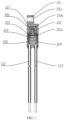
FIG. 1 is a cross-sectional view of a thermal cutoff according to Embodiment 1 of the present invention; -
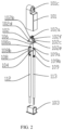
FIG. 2 is an exploded view of the thermal cutoff according to Embodiment 1 of the present invention; -
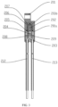
FIG. 3 is a cross-sectional view of a thermal cutoff according to Embodiment 2 of the present invention; and -
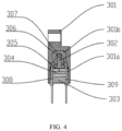
FIG. 4 is a cross-sectional view of a thermal cutoff according to Embodiment 3 of the present invention. - List of reference numerals:
- housing: 101, 201, 301
- first cavity: 101a, 201a, 301a
- second cavity: 101b, 201b, 301b
- mounting hole: 101c
- cover plate: 102, 202, 302
- bottom plate: 102e
- first partition plate: 102c
- second partition plate: 102d
- third partition plate: 102f
- undulating profiles: 102b, 102a
- sealant: 103, 203, 303
- current carrier: 104, 204, 304
- fuse link: 106, 206, 306
- fusing agent: 105, 205, 305
- arc extinguishing medium: 107, 207, 307
- first electrode plate: 108, 208, 308
- second electrode plate: 109, 209, 309
- one end of the first electrode plate: 108a
- one end of the second electrode plate: 109a
- first lead wire: 112, 212
- second lead wire: 113, 213
- clamping notch: 108b, 109b
- In order to make the objectives, technical solutions and advantages of the embodiments of the present invention clearer, the following embodiments of the present invention are described with reference to the drawings. The described embodiments are some rather than all of the embodiments of the present invention. Other embodiments obtained by those of ordinary skill in the art based on the embodiments presented without creative efforts shall fall within the protection scope of the present invention described, which is defined by the appended claims.
- The present invention provides the drawings to further illustrate the embodiments. The drawings, as a part of the disclosure of the present invention, are mainly used to illustrate the embodiments, and can explain the operating principles of the embodiments with reference to the related descriptions in this specification. With reference to such content, those of ordinary skill in the art can understand other possible implementations and the advantages of the present invention. Components in the drawings are not drawn to scale, and similar reference numerals generally represent similar components.
- The present invention is further described below with reference to the drawings and specific embodiments.
- To overcome the shortcomings of thermal cutoffs in the prior art, the present invention provides a thermal cutoff with an improved configuration as follows.
- As shown in
FIG. 1 andFIG. 2 , in the thermal cutoff of the present embodiment, a first fusible element and a second fusible element connected in parallel are provided as core functional devices in a closed cavity bounded by thehousing 101, thecover plate 102, and thesealant 103. Thehousing 101 has the first cavity (current-carrying fusing cavity) 101a and the second cavity (high-voltage fusing cavity) 101b corresponding to a current-carrying fusible element and a high-voltage fusible element, respectively. Thecover plate 102 is inserted into and fitted in an inner cavity of thehousing 101 to divide the inner cavity into thefirst cavity 101a and thesecond cavity 101b. A direction extending from a closed end to an open end of thehousing 101 is defined as a vertical direction. Thesecond cavity 101b and thefirst cavity 101a in the present embodiment are vertically arranged relatively to each other (as shown in the figure). As it should be recognized, in the present embodiment, thehousing 101 in a roughly rectangular shape connected to a semicircular piece is used as an example for description, while thecover plate 102 and thesealant 103 adapted to thehousing 101 also have matching shapes, but the shapes of thehousing 101, thecover plate 102 and thesealant 103 in the present embodiment should not be limited thereto. A person skilled in the art can adopt different shapes according to different applications and design requirements, but thehousing 101 is preferably in an elongated shape, such as a cylinder or a hexagonal prism. The direction extending along the length of thehousing 101 in an elongated shape is defined as the vertical direction. Thecover plate 102 is inserted into and matches the inner cavity of the housing 101 (where a gap between thecover plate 102 and thehousing 101 is also sealed by a small amount of sealant), and is located above thesealant 103 at the lower end, so that the inner cavity of thehousing 101 is divided and partitioned into thesecond cavity 101b and thefirst cavity 101a arranged vertically relatively to each other. Preferably, in the present embodiment, thehousing 101, thecover plate 102 and thesealant 103 are all made of materials with excellent insulation properties. For example, thehousing 101 and thecover plate 102 are made of ceramic, and thesealant 103 is made of epoxy resin. In addition, in the present embodiment, the mountinghole 101c is provided on the semicircular piece of thehousing 101, and the mountinghole 101c is configured for mounting and fixing to a protected device. - In the present embodiment, the first fusible element and the second fusible element serving as the core functional devices are described by taking a current-carrying fusible element and a high-voltage fusible element connected in parallel as an example. In the present embodiment, the current-carrying fusible element and the high-voltage fusible element are shown as the
U-shaped fuse link 106 and the straightcurrent carrier 104 arranged vertically relatively to each other. The melting point of thecurrent carrier 104 is lower than the melting point of thefuse link 106, and the internal resistance value of thecurrent carrier 104 is lower than the internal resistance value of thefuse link 106. Both ends of theU-shaped fuse link 106 have parallel segments. In this implementation, since the internal resistance value of thecurrent carrier 104 is lower than the internal resistance value of thefuse link 106, when a normal operating current is conducting, the current-carrying capacity is mainly provided by thecurrent carrier 104 serving as the current-carrying fusible element with a lower internal resistance value than thefuse link 106. Thecurrent carrier 104 is made of a fusible alloy. The fusible alloy generally refers to metal with a melting point of lower than 300°C and alloys thereof. For example, the fusible alloy is made of Bi, Sn, Pb, In and other metal elements with low melting points. The fuse link 106 also adopts an electrothermal heating element with a higher fusing temperature serving as a fusible element, such as a silver-copper alloy, a fusible alloy, a constantan wire, a Fe-Cr-Al heating element, or a nickel-chromium wire. - In the present embodiment, in the closed cavity bounded by the
housing 101, thecover plate 102, and thesealant 103, thefirst cavity 101a and thesecond cavity 101b are filled with the fusingagent 105 and thearc extinguishing medium 107, respectively. The fusingagent 105 contacts and wraps thecurrent carrier 104 provided in thefirst cavity 101a, while the arc extinguishing medium 107 contacts and wraps thefuse link 106 provided in thesecond cavity 101b. The fusingagent 105 is selected from substances capable of reducing the surface tension of an alloy to be fused, for example, a solder paste made of rosin substances (natural rosin, synthetic rosin, and the like). Thearc extinguishing medium 107 is selected from an arc extinguishing paste, quartz sand, sulfur hexafluoride, transformer oil, and the like. Under normal circumstances, the current mainly flows through thecurrent carrier 104. When a protected device has an abnormal temperature rise, the temperature is transferred to thecurrent carrier 104. When the temperature reaches the melting point of thecurrent carrier 104, thecurrent carrier 104 shrinks and breaks under the effect of the tension of thefusing agent 105, thereby breaking the parallel branch where thecurrent carrier 104 is located. At the moment when thecurrent carrier 104 fuses due to over-temperature, as the melting point of thefuse link 106 is higher than the melting point of thecurrent carrier 104, thefuse link 106 still maintains a conducting state, and the current is all loaded on thefuse link 106, making thefuse link 106 generate heat. Under a combined action of the increasing heat and the rising temperature, thefuse link 106 reaches its melting point, and then thefuse link 106 shrinks rapidly and fuses itself. An arc is inevitably generated during the breaking process. Due to the parallel segments formed by the U-shaped structure, an electric field with high strength is generated therebetween, in which electrons repel each other to elongate the arc and accelerate the recombination and diffusion of free electrons and positive ions, thereby quickly cutting off the arc and implementing high-voltage breaking. In addition, thesecond cavity 101b is filled with thearc extinguishing medium 107 for extinguishing the arc, thereby protecting the safety of the circuit. - It should be noted that similar to the current carrier, the fuse link in the present embodiment in some application scenarios is also a fusible alloy made of Bi, Sn, Pb, In and other metal elements with low melting points, provided that the fuse link meets the following requirements by adjusting ratios of the elements: the melting point of the fuse link is higher than the melting point of the current carrier, and the internal resistance value of the fuse link is higher than the internal resistance value of the current carrier. In such an application scenario, the arc extinguishing medium filled in the second cavity of the present embodiment is replaced with a fusing agent.
- In the present embodiment, the electrode for connecting the
current carrier 104 to thefuse link 106 includes thefirst electrode plate 108 and thesecond electrode plate 109. Thefirst electrode plate 108 and thesecond electrode plate 109 are of the same shape and are mirror-symmetric to facilitate mass production. Each of thefirst electrode plate 108 and thesecond electrode plate 109 is a roughly straight structure formed by stamping a conductive metal sheet. Oneend 108a (the upper end in the figure) of the straightfirst electrode plate 108 and oneend 109a (the upper end in the figure) of thesecond electrode plate 109 are bent to form small L-shaped segments, which form a welding table to be connected to the two ends of theU-shaped fuse link 106, respectively. Opposite sides (inner sides) at the middle positions of thefirst electrode plate 108 and thesecond electrode plate 109 are connected to the two ends of the straightcurrent carrier 104, respectively, to form an electrical parallel structure of thefuse link 106 and thecurrent carrier 104 arranged vertically relatively to each other, corresponding to thesecond cavity 101b and thefirst cavity 101a arranged vertically relatively to each other, respectively. - In the present embodiment, the
cover plate 102 includes thebottom plate 102e located at its lower end as well as thefirst partition plate 102c, thesecond partition plate 102d and thethird partition plate 102f that are perpendicular to thebottom plate 102e. Thefirst partition plate 102c and thesecond partition plate 102d are arranged in parallel at intervals, and thethird partition plate 102f is perpendicular to both thefirst partition plate 102c and thesecond partition plate 102d. Thethird partition plate 102f separates the parallel segments of theU-shaped fuse link 106, while thefirst partition plate 102c and thesecond partition plate 102d are configured to separate the two outer sides of thefuse link 106, respectively. Thefirst electrode plate 108 and thesecond electrode plate 109 are provided with the clampingnotches current carrier 104 and thefuse link 106 arranged vertically. Both sides of thebottom plate 102e of thecover plate 102 are provided with clamping grooves corresponding to the clampingnotches first electrode plate 108 and thesecond electrode plate 109, so that thecover plate 102 vertically separates thecurrent carrier 104 and thefuse link 106 relatively to each other. In addition, in order to increase the creepage distance to improve safety, the contours of each of thefirst partition plate 102c, thesecond partition plate 102d, and thethird partition plate 102f have the undulatingprofiles - To achieve better sealing protection performance to meet the requirements for use in the field of waterproofing, in the present embodiment, the other end (the lower end in the figure) of the
first electrode plate 108 is welded to thefirst lead wire 112, and the other end (the lower end in the figure) of thesecond electrode plate 109 is welded to thesecond lead wire 113, so as to form an electrical connection between thefirst lead wire 112, thefirst electrode plate 108, thecurrent carrier 104, thefuse link 106, thesecond electrode plate 109, and thesecond lead wire 113. In the present embodiment, thefirst lead wire 112 and thesecond lead wire 113 are welded to the inner sides of thefirst electrode plate 108 and thesecond electrode plate 109, respectively, and extend vertically downward. The welding between thefirst lead wire 112 and thefirst electrode plate 108 as well as the welding between thesecond electrode plate 109 and thesecond lead wire 113 are implemented by spot welding using tin solder, ultrasonic metal welding, or the like. Thefirst lead wire 112 and thesecond lead wire 113 are both multi-stranded wires, such as copper stranded wires, and thus can be bent more flexibly. Each of thefirst lead wire 112 and thesecond lead wire 113 is wrapped by an insulating sheath. The material of the insulating sheath is selected from Teflon, silicone rubber, a polyester material and other insulators with excellent insulation properties. In the present embodiment, thesealant 103 needs to meet filling requirements as follows: thesealant 103 at least covers the weld between thefirst lead wire 112 and thefirst electrode plate 108 and an end of thefirst lead wire 112, and also covers the weld between thesecond electrode plate 109 and thesecond lead wire 113 and an end of thesecond lead wire 113. - In addition, in the present embodiment, the
first lead wire 112 and thesecond lead wire 113 are led out from the same end and extend downward to form a package structure with a radial configuration. The package structure with the radial configuration is more suitable for the main circuit of the PTC heater than a package structure with axial configuration in the prior art, and does not need to fold back the wire harness at one end, which facilitates the mounting operation. In addition, the electrode plates are welded to the lead wires before being led out, and the welds and the ends of the lead wires are sealed with a sealant, so as to achieve an excellent sealing protection effect, which is in line with the requirements for use in the field of waterproofing. It should be noted that in other application scenarios, it is also feasible to replace the package structure with the radial configuration in Embodiment 1 by a package structure with an axial configuration similar to that in Chinese patent Nos.CN208093500U andCN206976273U in the prior art. - In addition, in Embodiment 1, since the first fusible element and the second fusible element (the current-carrying fusible element and the high-voltage fusible element) are arranged vertically relatively to each other, in such a structural configuration, the thermal cutoff in the present embodiment is longer and slimmer than the existing thermal cutoff with a parallel horizontal configuration, and is thus applicable to some occasions with specific needs. For example, in a heater of a liquid cooling system, due to the arrangement of the circuit board and other control parts, the space left for the thermal cutoff is relatively small. In this case, the prior parallel configuration is not suitable for positions with higher space requirements on compactness, and the thermal cutoff of the present embodiment can be used instead to meet such application requirements. In addition, Embodiment 1 adopts a sealed structural design to achieve an excellent sealing protection effect, which is in line with the requirements for use in the field of waterproofing. In addition, in the present embodiment, the current-carrying fusible element and the high-voltage fusible element are spaced apart, and the fuse link serving as the high-voltage fusible element is made of a material with higher voltage withstand capability and is filled with the arc extinguishing medium, so as to withstand a higher voltage level. The present embodiment adopts an elongated shape design while having a range of high-voltage applications, and is applicable to scenarios where the operating voltage is lower than 850-1000 VDC.
- As shown in
FIG. 3 , the thermal cutoff of Embodiment 2 is similar to that of Embodiment 1. In the thermal cutoff of the present embodiment, a current-carrying fusible element and a high-voltage fusible element connected in parallel are provided as core functional devices in a closed cavity bounded by thehousing 201, thecover plate 202, and thesealant 203. Thehousing 201 has the first cavity (current-carrying fusing cavity) 201a and the second cavity (high-voltage fusing cavity) 201b corresponding to the current-carrying fusible element and the high-voltage fusible element, respectively. Thecover plate 202 is inserted into and fitted in an inner cavity of thehousing 201 to divide the inner cavity into the first cavity 201a and thesecond cavity 201b arranged vertically relatively to each other. In the present embodiment, the current-carrying fusible element and the high-voltage fusible element connected in parallel are shown as theU-shaped fuse link 206 and the straightcurrent carrier 204 arranged vertically relatively to each other. The melting point of thecurrent carrier 204 is lower than the melting point of thefuse link 206, and the internal resistance value of thecurrent carrier 204 is lower than the internal resistance value of thefuse link 206. In the present embodiment, the first cavity 201a and thesecond cavity 201b are filled with the fusingagent 205 and the arc extinguishing medium 207 (which is alternatively a fusing agent depending on the material of the fuse link), respectively. The fusingagent 205 contacts and wraps thecurrent carrier 204 provided in the first cavity 201a, while the arc extinguishing medium 207 contacts and wraps thefuse link 206 provided in thesecond cavity 201b. - The difference between Embodiment 2 and Embodiment 1 is as follows. In the present embodiment, the
first electrode plate 208 and thesecond electrode plate 209 for connecting thecurrent carrier 204 to thefuse link 206 are roughly straight identical sheet structures that are mirror-symmetric and formed by stamping conductive metal sheets. The upper ends of thefirst electrode plate 208 and thesecond electrode plate 209 are not bent into a welding table similar to that in Embodiment 1, and theU-shaped fuse link 206 is directly welded to the upper ends thereof. In the present embodiment, thefirst electrode plate 208 and thesecond electrode plate 209 are less convenient to weld compared with Embodiment 1, but the stamping process of the electrode plate is simpler in manufacture and thus has certain cost advantages. In addition, another difference of the present embodiment is that the other end (the lower end in the figure) of thefirst electrode plate 208 is welded to thefirst lead wire 212 on the outer side, and the other end (the lower end in the figure) of thesecond electrode plate 209 is welded to thesecond lead wire 213 on the outer side. Compared with the welding operation at the inner sides in Embodiment 1, the welding operation in the present embodiment is simpler and more convenient while achieving the same sealing protection effect. - The thermal cutoff of Embodiment 3 is similar to that of Embodiment 1. In the thermal cutoff of the present embodiment, a current-carrying fusible element and a high-voltage fusible element connected in parallel are provided as core functional devices in a closed cavity bounded by the
housing 301, thecover plate 302, and thesealant 303. Thehousing 301 has the first cavity (current-carrying fusing cavity) 301a and the second cavity (high-voltage fusing cavity) 301b corresponding to the current-carrying fusible element and the high-voltage fusible element, respectively. Thecover plate 302 is inserted into and fitted in an inner cavity of thehousing 301 to divide the inner cavity into thefirst cavity 301a and thesecond cavity 301b arranged vertically relatively to each other. In the present embodiment, the current-carrying fusible element and the high-voltage fusible element connected in parallel are shown as theU-shaped fuse link 306 and the straightcurrent carrier 304 arranged vertically relatively to each other. The melting point of thecurrent carrier 304 is lower than the melting point of thefuse link 306, and the internal resistance value of thecurrent carrier 304 is lower than the internal resistance value of thefuse link 306. In the present embodiment, thefirst cavity 301a and thesecond cavity 301b are filled with the fusingagent 305 and the arc extinguishing medium 307 (which is alternatively a fusing agent depending on the material of the fuse link), respectively. The fusingagent 305 contacts and wraps thecurrent carrier 304 provided in thefirst cavity 301a, while the arc extinguishing medium 307 contacts and wraps thefuse link 306 provided in thesecond cavity 301b. - In the present embodiment, the electrode for connecting the
current carrier 304 to thefuse link 306 includes thefirst electrode plate 308 and thesecond electrode plate 309. Thefirst electrode plate 308 and thesecond electrode plate 309 are roughly straight structures formed by stamping conductive metal sheets, and are mirror-symmetric. One end (the upper end in the figure) of the straightfirst electrode plate 308 and one end (the upper end in the figure) of thesecond electrode plate 309 are bent to form small L-shaped segments, which form a welding table to be connected to the two ends of theU-shaped fuse link 306, respectively. Opposite sides (inner sides) at the middle positions of thefirst electrode plate 308 and thesecond electrode plate 309 are connected to the two ends of the straightcurrent carrier 304, respectively, to form an electrical parallel structure of thefuse link 306 and thecurrent carrier 304 arranged vertically relatively to each other, corresponding to thesecond cavity 301b and thefirst cavity 301a arranged vertically relatively to each other, respectively. The other ends (the lower ends in the figure) of thefirst electrode plate 308 and thesecond electrode plate 309 extend outside the opening of thehousing 301, such that thefirst electrode plate 308 and thesecond electrode plate 309 serve as electrode pins of the thermal cutoff and may be used as plug-in pins. - The difference between Embodiment 3 and Embodiment 1 is that in the present embodiment, the
first electrode plate 308 and thesecond electrode plate 309 for connecting thecurrent carrier 304 to thefuse link 306 extend outside the opening of thehousing 301 as electrode pins, while removing the two lead wires each wrapped by an insulating sheath as in Embodiment 1. Compared with Embodiment 1, the present embodiment has a lower protection rating, but is simpler in manufacture and economizes on materials, and thus has a certain cost advantage while meeting general protection requirements. - Additionally, it should be noted that in Embodiment 1 to Embodiment 3 above, the current-carrying fusible element and the high-voltage fusible element connected in parallel are as shown as examples of the fusible elements, and can be applied in high-voltage occasions. However, in other lower-voltage occasions, it is also feasible to implement the first fusible element and the second fusible element by adopting two parallel, vertically arranged (relatively to each other) fusible alloys made of metal elements with low melting points, such as Bi, Sn, Pb, and In (similar to
CN206976273U ) to form a thermal cutoff that has a more elongated shape (compared withCN206976273U ). - The embodiments of the device described above are merely illustrative, where units described as separate components may or may not be physically separated. Components displayed as units may or may not be physical units, that is, the components may be located in one place, or may be distributed to multiple network units. Some or all of the modules may be selected according to actual needs to achieve the objective of the solution of the embodiment. Those of ordinary skill in the art can understand and implement the present invention without creative efforts.
- The phrase "an/one embodiment", "embodiment" or "one or more embodiments" mentioned herein means that a specific feature, structure, or characteristic described in combination with the embodiment is included in at least one embodiment of the present invention. In addition, it should be noted that the phrase example "in an/one embodiment" herein does not necessarily refer to the same embodiment.
- In the specification provided herein, a large number of specific details are described. However, it can be understood that the embodiments of the present invention can be practiced without the specific details. In some embodiments, well-known methods, structures and techniques are not shown in detail to avoid obscuring the understanding of this specification.
- In the claims, any reference sign between brackets should not be constructed as a limitation to the claims. The word "include/comprise" does not exclude the presence of elements or steps not listed in the claims. The word "one" or "alan" preceding an element does not exclude the existence of multiple such elements. The present invention can be implemented with the assistance of hardware including several different components and the assistance of a properly programmed computer. In the claims of a unit where several devices are listed, several of the devices may be embodied by the same hardware item. The words such as first, second, and third are not used to indicate any order or sequence and may be interpreted as names.
- Finally, it should be noted that the foregoing embodiments are merely used to explain the technical solutions of the present invention, but are not intended to limit the same. Although the present invention is described in detail with reference to the foregoing embodiments, those of ordinary skill in the art should understand that they can still modify the technical solutions described in the foregoing embodiments, or make equivalent substitutions on some technical features therein.
Claims (3)
- A thermal cutoff having elongated shape with a vertical configuration, comprisinga first fusible element,a second fusible element, anda closed cavity bounded by a housing (101, 201, 301) with an open end, a cover plate (102, 202, 302), and a sealant (103, 203, 303), wherein a direction extending from a closed end of the housing to the open end of the housing is defined as the vertical direction; the first fusible element and the second fusible element are provided in the closed cavity and arranged relatively to each other in the vertical direction; two ends of the first fusible element and two ends of the second fusible element are connected in parallel to a first electrode plate (108, 208, 308) and a second electrode plate (109, 209, 309), respectively; the first fusible element is a current-carrying fusible element, and the second fusible element is a high-voltage fusible element; the current-carrying fusible element comprises a current carrier (104, 204, 304), and the high-voltage fusible element comprises a U-shaped fuse link (106, 206, 306) with parallel segments at two ends; wherein a melting point of the current carrier is lower than a melting point of the fuse link, and an internal resistance value of the current carrier is lower than an internal resistance value of the fuse link; whereinthe cover plate (102, 202, 302) is inserted and fitted in the closed cavity to divide the closed cavity into a first cavity (101a, 201a, 301a) and a second cavity (101b, 201b, 301b), wherein the first cavity (101a, 201a, 301a) and the second cavity (101b, 201b, 301b) are arranged relatively to each other in the vertical direction; and the first fusible element and second fusible element are arranged in the first cavity (101a, 201a, 301a) and the second cavity (101b, 201b, 301b), respectively;the cover plate (102, 202, 302) comprises a bottom plate (102e), a first partition plate (102c), a second partition plate (102d), and a third partition plate (102f); whereinthe bottom plate (102e) is located at a lower end of the cover plate (102, 202, 302);the first partition plate (102c), the second partition plate (102d), and the third partition plate (102f) are perpendicular to the bottom plate (102e);the first partition plate (102c) and the second partition plate (102d) are arranged in parallel at intervals;the third partition plate (102f) is perpendicular to both the first partition plate (102c) and the second partition plate (102d);the third partition plate (102f) separates parallel segments of the fuse link (106, 206, 306) from each other; andthe first partition plate (102c) and the second partition plate (102d) are configured for separating two outer sides of the fuse link (106, 206, 306), respectively.
- The thermal cutoff according to claim 1, whereinthe first electrode plate and the second electrode plate are provided with clamping notches (108b, 109b) between the current carrier and the fuse link arranged relatively to each other in the vertical direction;both sides of the bottom plate of the cover plate are provided with clamping grooves corresponding to the clamping notches of the first electrode plate and the second electrode plate, andthe cover plate vertically separates the current carrier and the fuse link relatively to each other.
- The thermal cutoff according to claim 2, wherein
the first partition plate, the second partition plate and the third partition plate each have undulating profiles (102b, 102a) to increase a creepage distance.
Applications Claiming Priority (2)
| Application Number | Priority Date | Filing Date | Title |
|---|---|---|---|
| CN201920354677.3U CN209434140U (en) | 2019-03-20 | 2019-03-20 | Thermal Cutoffs |
| PCT/CN2019/106809 WO2020186713A1 (en) | 2019-03-20 | 2019-09-19 | Thermal cutoff |
Publications (3)
| Publication Number | Publication Date |
|---|---|
| EP3910661A1 EP3910661A1 (en) | 2021-11-17 |
| EP3910661A4 EP3910661A4 (en) | 2022-03-23 |
| EP3910661B1 true EP3910661B1 (en) | 2023-04-12 |
Family
ID=67978751
Family Applications (1)
| Application Number | Title | Priority Date | Filing Date |
|---|---|---|---|
| EP19920100.5A Active EP3910661B1 (en) | 2019-03-20 | 2019-09-19 | Thermal cutoff |
Country Status (5)
| Country | Link |
|---|---|
| US (1) | US11574785B2 (en) |
| EP (1) | EP3910661B1 (en) |
| KR (1) | KR102574581B1 (en) |
| CN (1) | CN209434140U (en) |
| WO (1) | WO2020186713A1 (en) |
Family Cites Families (18)
| Publication number | Priority date | Publication date | Assignee | Title |
|---|---|---|---|---|
| JPH06504875A (en) | 1991-01-16 | 1994-06-02 | ダブ | Flat type fuse for high rated current |
| JP3194429B2 (en) * | 1998-06-02 | 2001-07-30 | オムロン株式会社 | Overcurrent cutoff structure |
| EP1274110A1 (en) * | 2001-07-02 | 2003-01-08 | Abb Research Ltd. | Fuse |
| JP4230194B2 (en) * | 2002-10-30 | 2009-02-25 | 内橋エステック株式会社 | Alloy type thermal fuse and wire for thermal fuse element |
| JP4514669B2 (en) * | 2005-07-29 | 2010-07-28 | エヌイーシー ショット コンポーネンツ株式会社 | Protection device using thermal fuse |
| US7741946B2 (en) * | 2007-07-25 | 2010-06-22 | Thinking Electronics Industrial Co., Ltd. | Metal oxide varistor with heat protection |
| CN101859665A (en) * | 2009-04-07 | 2010-10-13 | 厦门赛尔特电子有限公司 | A high ampacity alloy type thermal fuse |
| CN202094065U (en) * | 2010-06-18 | 2011-12-28 | 厦门赛尔特电子有限公司 | Heavy current fuse protector |
| CN102054636A (en) * | 2010-12-29 | 2011-05-11 | 徐周 | Temperature fuse |
| CN203839326U (en) * | 2014-05-07 | 2014-09-17 | 厦门赛尔特电子有限公司 | High-voltage direct-current temperature fuse |
| CA2892220C (en) * | 2014-06-30 | 2021-01-26 | Matthew Rain Darr | Pluggable touch-safe fuse module with built-in removal handle |
| CN205900482U (en) * | 2016-06-07 | 2017-01-18 | 厦门赛尔特电子有限公司 | Lamination type temperature safeties |
| CN109216128A (en) * | 2017-06-30 | 2019-01-15 | 厦门赛尔特电子有限公司 | A kind of high voltage direct current thermal cut-off |
| CN206976273U (en) | 2017-06-30 | 2018-02-06 | 厦门赛尔特电子有限公司 | A kind of HVDC thermal cut-off |
| CN207097772U (en) * | 2017-08-02 | 2018-03-13 | 厦门赛尔特电子有限公司 | Alloy-type temperature fuse |
| CN207320047U (en) * | 2017-10-24 | 2018-05-04 | 漳州雅宝电子有限公司 | A kind of Thermal Cutoffs of pin tape insulation casing |
| CN208173540U (en) * | 2018-03-21 | 2018-11-30 | 厦门赛尔特电子有限公司 | A kind of Thermal Cutoffs with arc-extinguishing medium |
| CN208093500U (en) | 2018-04-03 | 2018-11-13 | 厦门赛尔特电子有限公司 | A kind of high-tension fuse |
-
2019
- 2019-03-20 CN CN201920354677.3U patent/CN209434140U/en active Active
- 2019-09-19 WO PCT/CN2019/106809 patent/WO2020186713A1/en not_active Ceased
- 2019-09-19 EP EP19920100.5A patent/EP3910661B1/en active Active
- 2019-09-19 US US17/293,827 patent/US11574785B2/en active Active
- 2019-09-19 KR KR1020217022433A patent/KR102574581B1/en active Active
Also Published As
| Publication number | Publication date |
|---|---|
| US11574785B2 (en) | 2023-02-07 |
| EP3910661A4 (en) | 2022-03-23 |
| EP3910661A1 (en) | 2021-11-17 |
| WO2020186713A1 (en) | 2020-09-24 |
| US20220013319A1 (en) | 2022-01-13 |
| KR20210104120A (en) | 2021-08-24 |
| CN209434140U (en) | 2019-09-24 |
| KR102574581B1 (en) | 2023-09-04 |
Similar Documents
| Publication | Publication Date | Title |
|---|---|---|
| KR102622668B1 (en) | Bus bar and battery pack including the same | |
| US8133608B2 (en) | Battery pack with cell-level fusing | |
| US3261950A (en) | Time-lag fuses having high thermal efficiency | |
| US20030001716A1 (en) | Fusible link | |
| ES2493071T3 (en) | Circuit protection device for photovoltaic systems | |
| US4417224A (en) | Time delay fuse | |
| US11574787B2 (en) | Thermal cutoff | |
| US11621138B2 (en) | High-voltage fusing apparatus | |
| US9490096B2 (en) | Medium voltage controllable fuse | |
| US11710613B2 (en) | Melting conductor and fuse | |
| CN110310872B (en) | Multi-section lightning current-resistant fusing structure and fuse adopting same | |
| US4091353A (en) | Current limiting fuse | |
| CN214043586U (en) | Fuse protector | |
| US4058785A (en) | Current limiting fuse | |
| US11574785B2 (en) | Thermal cutoff | |
| CN211605081U (en) | A double-circuit cut-off temperature fuse | |
| KR20240166157A (en) | Fuse element | |
| CN213425414U (en) | Overvoltage protection element and component assembly for an overvoltage protection element | |
| JP3829692B2 (en) | Current limiter | |
| JP2025093239A (en) | Battery pack | |
| KR20170097711A (en) | Protective element | |
| IT202100008117A1 (en) | BI-PHASE EXTHERMIC REACTION CURRENT LIMITING FUSES, WITH HIGH BREAKING CAPACITY (HRC) FOR THE PROTECTION OF DIRECT CURRENT CIRCUITS FROM OVERCURRENT |
Legal Events
| Date | Code | Title | Description |
|---|---|---|---|
| STAA | Information on the status of an ep patent application or granted ep patent |
Free format text: STATUS: THE INTERNATIONAL PUBLICATION HAS BEEN MADE |
|
| PUAI | Public reference made under article 153(3) epc to a published international application that has entered the european phase |
Free format text: ORIGINAL CODE: 0009012 |
|
| STAA | Information on the status of an ep patent application or granted ep patent |
Free format text: STATUS: REQUEST FOR EXAMINATION WAS MADE |
|
| 17P | Request for examination filed |
Effective date: 20210810 |
|
| AK | Designated contracting states |
Kind code of ref document: A1 Designated state(s): AL AT BE BG CH CY CZ DE DK EE ES FI FR GB GR HR HU IE IS IT LI LT LU LV MC MK MT NL NO PL PT RO RS SE SI SK SM TR |
|
| A4 | Supplementary search report drawn up and despatched |
Effective date: 20220222 |
|
| RIC1 | Information provided on ipc code assigned before grant |
Ipc: H01H 85/38 20060101ALN20220216BHEP Ipc: H01H 85/18 20060101ALN20220216BHEP Ipc: H01H 85/08 20060101ALN20220216BHEP Ipc: H01H 85/175 20060101ALI20220216BHEP Ipc: H01H 85/12 20060101ALI20220216BHEP Ipc: H01H 37/76 20060101AFI20220216BHEP |
|
| STAA | Information on the status of an ep patent application or granted ep patent |
Free format text: STATUS: EXAMINATION IS IN PROGRESS |
|
| 17Q | First examination report despatched |
Effective date: 20220531 |
|
| DAV | Request for validation of the european patent (deleted) | ||
| DAX | Request for extension of the european patent (deleted) | ||
| REG | Reference to a national code |
Ref country code: DE Ref legal event code: R079 Ref document number: 602019027587 Country of ref document: DE Free format text: PREVIOUS MAIN CLASS: H01H0085060000 Ipc: H01H0037760000 |
|
| GRAP | Despatch of communication of intention to grant a patent |
Free format text: ORIGINAL CODE: EPIDOSNIGR1 |
|
| STAA | Information on the status of an ep patent application or granted ep patent |
Free format text: STATUS: GRANT OF PATENT IS INTENDED |
|
| RIC1 | Information provided on ipc code assigned before grant |
Ipc: H01H 85/38 20060101ALN20221116BHEP Ipc: H01H 85/18 20060101ALN20221116BHEP Ipc: H01H 85/08 20060101ALN20221116BHEP Ipc: H01H 85/175 20060101ALI20221116BHEP Ipc: H01H 85/12 20060101ALI20221116BHEP Ipc: H01H 37/76 20060101AFI20221116BHEP |
|
| INTG | Intention to grant announced |
Effective date: 20221208 |
|
| GRAS | Grant fee paid |
Free format text: ORIGINAL CODE: EPIDOSNIGR3 |
|
| GRAA | (expected) grant |
Free format text: ORIGINAL CODE: 0009210 |
|
| STAA | Information on the status of an ep patent application or granted ep patent |
Free format text: STATUS: THE PATENT HAS BEEN GRANTED |
|
| AK | Designated contracting states |
Kind code of ref document: B1 Designated state(s): AL AT BE BG CH CY CZ DE DK EE ES FI FR GB GR HR HU IE IS IT LI LT LU LV MC MK MT NL NO PL PT RO RS SE SI SK SM TR |
|
| REG | Reference to a national code |
Ref country code: GB Ref legal event code: FG4D |
|
| REG | Reference to a national code |
Ref country code: CH Ref legal event code: EP |
|
| REG | Reference to a national code |
Ref country code: DE Ref legal event code: R096 Ref document number: 602019027587 Country of ref document: DE |
|
| REG | Reference to a national code |
Ref country code: IE Ref legal event code: FG4D |
|
| REG | Reference to a national code |
Ref country code: AT Ref legal event code: REF Ref document number: 1560251 Country of ref document: AT Kind code of ref document: T Effective date: 20230515 |
|
| REG | Reference to a national code |
Ref country code: SE Ref legal event code: TRGR |
|
| PGFP | Annual fee paid to national office [announced via postgrant information from national office to epo] |
Ref country code: FR Payment date: 20230620 Year of fee payment: 5 |
|
| REG | Reference to a national code |
Ref country code: LT Ref legal event code: MG9D |
|
| REG | Reference to a national code |
Ref country code: NL Ref legal event code: MP Effective date: 20230412 |
|
| PGFP | Annual fee paid to national office [announced via postgrant information from national office to epo] |
Ref country code: SE Payment date: 20230620 Year of fee payment: 5 |
|
| REG | Reference to a national code |
Ref country code: AT Ref legal event code: MK05 Ref document number: 1560251 Country of ref document: AT Kind code of ref document: T Effective date: 20230412 |
|
| PG25 | Lapsed in a contracting state [announced via postgrant information from national office to epo] |
Ref country code: NL Free format text: LAPSE BECAUSE OF FAILURE TO SUBMIT A TRANSLATION OF THE DESCRIPTION OR TO PAY THE FEE WITHIN THE PRESCRIBED TIME-LIMIT Effective date: 20230412 |
|
| PG25 | Lapsed in a contracting state [announced via postgrant information from national office to epo] |
Ref country code: PT Free format text: LAPSE BECAUSE OF FAILURE TO SUBMIT A TRANSLATION OF THE DESCRIPTION OR TO PAY THE FEE WITHIN THE PRESCRIBED TIME-LIMIT Effective date: 20230814 Ref country code: NO Free format text: LAPSE BECAUSE OF FAILURE TO SUBMIT A TRANSLATION OF THE DESCRIPTION OR TO PAY THE FEE WITHIN THE PRESCRIBED TIME-LIMIT Effective date: 20230712 Ref country code: ES Free format text: LAPSE BECAUSE OF FAILURE TO SUBMIT A TRANSLATION OF THE DESCRIPTION OR TO PAY THE FEE WITHIN THE PRESCRIBED TIME-LIMIT Effective date: 20230412 Ref country code: AT Free format text: LAPSE BECAUSE OF FAILURE TO SUBMIT A TRANSLATION OF THE DESCRIPTION OR TO PAY THE FEE WITHIN THE PRESCRIBED TIME-LIMIT Effective date: 20230412 |
|
| PG25 | Lapsed in a contracting state [announced via postgrant information from national office to epo] |
Ref country code: RS Free format text: LAPSE BECAUSE OF FAILURE TO SUBMIT A TRANSLATION OF THE DESCRIPTION OR TO PAY THE FEE WITHIN THE PRESCRIBED TIME-LIMIT Effective date: 20230412 Ref country code: PL Free format text: LAPSE BECAUSE OF FAILURE TO SUBMIT A TRANSLATION OF THE DESCRIPTION OR TO PAY THE FEE WITHIN THE PRESCRIBED TIME-LIMIT Effective date: 20230412 Ref country code: LV Free format text: LAPSE BECAUSE OF FAILURE TO SUBMIT A TRANSLATION OF THE DESCRIPTION OR TO PAY THE FEE WITHIN THE PRESCRIBED TIME-LIMIT Effective date: 20230412 Ref country code: LT Free format text: LAPSE BECAUSE OF FAILURE TO SUBMIT A TRANSLATION OF THE DESCRIPTION OR TO PAY THE FEE WITHIN THE PRESCRIBED TIME-LIMIT Effective date: 20230412 Ref country code: IS Free format text: LAPSE BECAUSE OF FAILURE TO SUBMIT A TRANSLATION OF THE DESCRIPTION OR TO PAY THE FEE WITHIN THE PRESCRIBED TIME-LIMIT Effective date: 20230812 Ref country code: HR Free format text: LAPSE BECAUSE OF FAILURE TO SUBMIT A TRANSLATION OF THE DESCRIPTION OR TO PAY THE FEE WITHIN THE PRESCRIBED TIME-LIMIT Effective date: 20230412 Ref country code: GR Free format text: LAPSE BECAUSE OF FAILURE TO SUBMIT A TRANSLATION OF THE DESCRIPTION OR TO PAY THE FEE WITHIN THE PRESCRIBED TIME-LIMIT Effective date: 20230713 Ref country code: AL Free format text: LAPSE BECAUSE OF FAILURE TO SUBMIT A TRANSLATION OF THE DESCRIPTION OR TO PAY THE FEE WITHIN THE PRESCRIBED TIME-LIMIT Effective date: 20230412 |
|
| PG25 | Lapsed in a contracting state [announced via postgrant information from national office to epo] |
Ref country code: FI Free format text: LAPSE BECAUSE OF FAILURE TO SUBMIT A TRANSLATION OF THE DESCRIPTION OR TO PAY THE FEE WITHIN THE PRESCRIBED TIME-LIMIT Effective date: 20230412 |
|
| REG | Reference to a national code |
Ref country code: DE Ref legal event code: R097 Ref document number: 602019027587 Country of ref document: DE |
|
| PG25 | Lapsed in a contracting state [announced via postgrant information from national office to epo] |
Ref country code: SK Free format text: LAPSE BECAUSE OF FAILURE TO SUBMIT A TRANSLATION OF THE DESCRIPTION OR TO PAY THE FEE WITHIN THE PRESCRIBED TIME-LIMIT Effective date: 20230412 |
|
| PG25 | Lapsed in a contracting state [announced via postgrant information from national office to epo] |
Ref country code: SM Free format text: LAPSE BECAUSE OF FAILURE TO SUBMIT A TRANSLATION OF THE DESCRIPTION OR TO PAY THE FEE WITHIN THE PRESCRIBED TIME-LIMIT Effective date: 20230412 Ref country code: SK Free format text: LAPSE BECAUSE OF FAILURE TO SUBMIT A TRANSLATION OF THE DESCRIPTION OR TO PAY THE FEE WITHIN THE PRESCRIBED TIME-LIMIT Effective date: 20230412 Ref country code: RO Free format text: LAPSE BECAUSE OF FAILURE TO SUBMIT A TRANSLATION OF THE DESCRIPTION OR TO PAY THE FEE WITHIN THE PRESCRIBED TIME-LIMIT Effective date: 20230412 Ref country code: EE Free format text: LAPSE BECAUSE OF FAILURE TO SUBMIT A TRANSLATION OF THE DESCRIPTION OR TO PAY THE FEE WITHIN THE PRESCRIBED TIME-LIMIT Effective date: 20230412 Ref country code: DK Free format text: LAPSE BECAUSE OF FAILURE TO SUBMIT A TRANSLATION OF THE DESCRIPTION OR TO PAY THE FEE WITHIN THE PRESCRIBED TIME-LIMIT Effective date: 20230412 Ref country code: CZ Free format text: LAPSE BECAUSE OF FAILURE TO SUBMIT A TRANSLATION OF THE DESCRIPTION OR TO PAY THE FEE WITHIN THE PRESCRIBED TIME-LIMIT Effective date: 20230412 |
|
| PLBE | No opposition filed within time limit |
Free format text: ORIGINAL CODE: 0009261 |
|
| STAA | Information on the status of an ep patent application or granted ep patent |
Free format text: STATUS: NO OPPOSITION FILED WITHIN TIME LIMIT |
|
| 26N | No opposition filed |
Effective date: 20240115 |
|
| REG | Reference to a national code |
Ref country code: CH Ref legal event code: PL |
|
| PG25 | Lapsed in a contracting state [announced via postgrant information from national office to epo] |
Ref country code: SI Free format text: LAPSE BECAUSE OF FAILURE TO SUBMIT A TRANSLATION OF THE DESCRIPTION OR TO PAY THE FEE WITHIN THE PRESCRIBED TIME-LIMIT Effective date: 20230412 |
|
| PG25 | Lapsed in a contracting state [announced via postgrant information from national office to epo] |
Ref country code: LU Free format text: LAPSE BECAUSE OF NON-PAYMENT OF DUE FEES Effective date: 20230919 |
|
| REG | Reference to a national code |
Ref country code: BE Ref legal event code: MM Effective date: 20230930 |
|
| GBPC | Gb: european patent ceased through non-payment of renewal fee |
Effective date: 20230919 |
|
| PG25 | Lapsed in a contracting state [announced via postgrant information from national office to epo] |
Ref country code: SI Free format text: LAPSE BECAUSE OF FAILURE TO SUBMIT A TRANSLATION OF THE DESCRIPTION OR TO PAY THE FEE WITHIN THE PRESCRIBED TIME-LIMIT Effective date: 20230412 Ref country code: LU Free format text: LAPSE BECAUSE OF NON-PAYMENT OF DUE FEES Effective date: 20230919 Ref country code: IT Free format text: LAPSE BECAUSE OF FAILURE TO SUBMIT A TRANSLATION OF THE DESCRIPTION OR TO PAY THE FEE WITHIN THE PRESCRIBED TIME-LIMIT Effective date: 20230412 Ref country code: MC Free format text: LAPSE BECAUSE OF FAILURE TO SUBMIT A TRANSLATION OF THE DESCRIPTION OR TO PAY THE FEE WITHIN THE PRESCRIBED TIME-LIMIT Effective date: 20230412 |
|
| REG | Reference to a national code |
Ref country code: IE Ref legal event code: MM4A |
|
| PG25 | Lapsed in a contracting state [announced via postgrant information from national office to epo] |
Ref country code: IE Free format text: LAPSE BECAUSE OF NON-PAYMENT OF DUE FEES Effective date: 20230919 |
|
| PG25 | Lapsed in a contracting state [announced via postgrant information from national office to epo] |
Ref country code: GB Free format text: LAPSE BECAUSE OF NON-PAYMENT OF DUE FEES Effective date: 20230919 |
|
| PG25 | Lapsed in a contracting state [announced via postgrant information from national office to epo] |
Ref country code: CH Free format text: LAPSE BECAUSE OF NON-PAYMENT OF DUE FEES Effective date: 20230930 |
|
| PG25 | Lapsed in a contracting state [announced via postgrant information from national office to epo] |
Ref country code: IE Free format text: LAPSE BECAUSE OF NON-PAYMENT OF DUE FEES Effective date: 20230919 Ref country code: GB Free format text: LAPSE BECAUSE OF NON-PAYMENT OF DUE FEES Effective date: 20230919 Ref country code: CH Free format text: LAPSE BECAUSE OF NON-PAYMENT OF DUE FEES Effective date: 20230930 |
|
| PG25 | Lapsed in a contracting state [announced via postgrant information from national office to epo] |
Ref country code: BE Free format text: LAPSE BECAUSE OF NON-PAYMENT OF DUE FEES Effective date: 20230930 |
|
| PG25 | Lapsed in a contracting state [announced via postgrant information from national office to epo] |
Ref country code: BG Free format text: LAPSE BECAUSE OF FAILURE TO SUBMIT A TRANSLATION OF THE DESCRIPTION OR TO PAY THE FEE WITHIN THE PRESCRIBED TIME-LIMIT Effective date: 20230412 |
|
| PG25 | Lapsed in a contracting state [announced via postgrant information from national office to epo] |
Ref country code: BG Free format text: LAPSE BECAUSE OF FAILURE TO SUBMIT A TRANSLATION OF THE DESCRIPTION OR TO PAY THE FEE WITHIN THE PRESCRIBED TIME-LIMIT Effective date: 20230412 |
|
| REG | Reference to a national code |
Ref country code: SE Ref legal event code: EUG |
|
| PG25 | Lapsed in a contracting state [announced via postgrant information from national office to epo] |
Ref country code: FR Free format text: LAPSE BECAUSE OF NON-PAYMENT OF DUE FEES Effective date: 20240930 |
|
| PG25 | Lapsed in a contracting state [announced via postgrant information from national office to epo] |
Ref country code: CY Free format text: LAPSE BECAUSE OF FAILURE TO SUBMIT A TRANSLATION OF THE DESCRIPTION OR TO PAY THE FEE WITHIN THE PRESCRIBED TIME-LIMIT; INVALID AB INITIO Effective date: 20190919 |
|
| PG25 | Lapsed in a contracting state [announced via postgrant information from national office to epo] |
Ref country code: HU Free format text: LAPSE BECAUSE OF FAILURE TO SUBMIT A TRANSLATION OF THE DESCRIPTION OR TO PAY THE FEE WITHIN THE PRESCRIBED TIME-LIMIT; INVALID AB INITIO Effective date: 20190919 |
|
| PGFP | Annual fee paid to national office [announced via postgrant information from national office to epo] |
Ref country code: DE Payment date: 20250826 Year of fee payment: 7 |
|
| PG25 | Lapsed in a contracting state [announced via postgrant information from national office to epo] |
Ref country code: SE Free format text: LAPSE BECAUSE OF NON-PAYMENT OF DUE FEES Effective date: 20240920 |
|
| PG25 | Lapsed in a contracting state [announced via postgrant information from national office to epo] |
Ref country code: TR Free format text: LAPSE BECAUSE OF FAILURE TO SUBMIT A TRANSLATION OF THE DESCRIPTION OR TO PAY THE FEE WITHIN THE PRESCRIBED TIME-LIMIT Effective date: 20230412 |