EP3910657A1 - A switching apparatus for electric power distribution grids - Google Patents
A switching apparatus for electric power distribution grids Download PDFInfo
- Publication number
- EP3910657A1 EP3910657A1 EP20174616.1A EP20174616A EP3910657A1 EP 3910657 A1 EP3910657 A1 EP 3910657A1 EP 20174616 A EP20174616 A EP 20174616A EP 3910657 A1 EP3910657 A1 EP 3910657A1
- Authority
- EP
- European Patent Office
- Prior art keywords
- arc
- breaking
- switching apparatus
- breaking plates
- electric
- Prior art date
- Legal status (The legal status is an assumption and is not a legal conclusion. Google has not performed a legal analysis and makes no representation as to the accuracy of the status listed.)
- Granted
Links
Images




Classifications
-
- H—ELECTRICITY
- H01—ELECTRIC ELEMENTS
- H01H—ELECTRIC SWITCHES; RELAYS; SELECTORS; EMERGENCY PROTECTIVE DEVICES
- H01H33/00—High-tension or heavy-current switches with arc-extinguishing or arc-preventing means
- H01H33/02—Details
- H01H33/04—Means for extinguishing or preventing arc between current-carrying parts
- H01H33/08—Stationary parts for restricting or subdividing the arc, e.g. barrier plate
- H01H33/10—Metal parts
-
- H—ELECTRICITY
- H01—ELECTRIC ELEMENTS
- H01H—ELECTRIC SWITCHES; RELAYS; SELECTORS; EMERGENCY PROTECTIVE DEVICES
- H01H9/00—Details of switching devices, not covered by groups H01H1/00 - H01H7/00
- H01H9/30—Means for extinguishing or preventing arc between current-carrying parts
- H01H9/34—Stationary parts for restricting or subdividing the arc, e.g. barrier plate
- H01H9/36—Metal parts
-
- H—ELECTRICITY
- H01—ELECTRIC ELEMENTS
- H01H—ELECTRIC SWITCHES; RELAYS; SELECTORS; EMERGENCY PROTECTIVE DEVICES
- H01H9/00—Details of switching devices, not covered by groups H01H1/00 - H01H7/00
- H01H9/30—Means for extinguishing or preventing arc between current-carrying parts
- H01H9/34—Stationary parts for restricting or subdividing the arc, e.g. barrier plate
- H01H9/36—Metal parts
- H01H2009/365—Metal parts using U-shaped plates
-
- H—ELECTRICITY
- H01—ELECTRIC ELEMENTS
- H01H—ELECTRIC SWITCHES; RELAYS; SELECTORS; EMERGENCY PROTECTIVE DEVICES
- H01H9/00—Details of switching devices, not covered by groups H01H1/00 - H01H7/00
- H01H9/54—Circuit arrangements not adapted to a particular application of the switching device and for which no provision exists elsewhere
- H01H9/541—Contacts shunted by semiconductor devices
- H01H9/542—Contacts shunted by static switch means
- H01H2009/543—Contacts shunted by static switch means third parallel branch comprising an energy absorber, e.g. MOV, PTC, Zener
-
- H—ELECTRICITY
- H01—ELECTRIC ELEMENTS
- H01H—ELECTRIC SWITCHES; RELAYS; SELECTORS; EMERGENCY PROTECTIVE DEVICES
- H01H9/00—Details of switching devices, not covered by groups H01H1/00 - H01H7/00
- H01H9/54—Circuit arrangements not adapted to a particular application of the switching device and for which no provision exists elsewhere
- H01H9/541—Contacts shunted by semiconductor devices
- H01H9/542—Contacts shunted by static switch means
Definitions
- the present invention relates to a switching apparatus for electric power distribution grids, in particular for medium-voltage electric systems.
- Switching apparatuses for electric power distribution grids generally comprise one or more electrical poles, each including electric contacts that can be mutually coupled or uncoupled.
- switching apparatuses In order to break line currents circulating along the electric poles, such electric arcs have to be extinguished as quickly as possible.
- switching apparatuses often comprise an arc-chute arrangement positioned near the electric contacts of each electric pole.
- An arc-chute arrangement typically includes a stack of arc-breaking plates made of a metallic ferromagnetic material and arranged spaced one from another.
- the main aim of the present invention is to provide a switching apparatus for electric power distribution grids that allows overcoming the drawbacks of the known art.
- a purpose of the present invention is to provide a switching apparatus having electric poles provided with an arc-breaking assembly capable of preventing or reducing the bridging of electric arc segments on the top and along the sides of the arc-breaking plates during an opening manoeuvre.
- a further purpose of the present invention is to provide a switching apparatus, which shows improved commutation efficiency during an opening manoeuvre.
- a further purpose of the present invention is to provide a switching apparatus, which is relatively simple and cheap to be manufactured at industrial levels.
- the switching apparatus comprises:
- the arc-breaking plates comprise a first portion made of a ferromagnetic material and a second portion made of a metallic non-ferromagnetic material.
- the ferromagnetic and non-ferromagnetic portions of said arc-breaking plates are respectively in a proximal position and in a distal position with respect to the movable contact, during a manoeuvre of said switching apparatus.
- the arc-breaking plates comprise opposite first and second sides defining a first dimension of said arc-breaking plates and opposite third and fourth sides defining a second dimension of said arc-breaking plates.
- the first and second sides of said arc-breaking plates are respectively in a proximal position and in a distal position with respect to said movable contact, during a manoeuvre of said switching apparatus.
- the arc-breaking plates comprise, at said first side, a groove through which said movable contact passes, during a manoeuvre of said switching apparatus.
- the first and second portions of said arc-breaking plates are respectively in a proximal position and in a distal position with respect to said groove.
- the first portion of said arc-breaking plates includes at least a portion of the first side of said arc-breaking plates.
- the first portion of said arc-breaking plates includes the first side and at least a portion of the third and fourth sides of said arc-breaking plates.
- the first portion of said arc-breaking plates is configured surrounds the groove of said arc-breaking plates.
- the second portion of said arc-breaking plates surrounds the first portion of said arc-breaking plates
- the switching apparatus comprises, for each electric pole, an arc chamber including said fixed contact, said movable contact and said arc-breaking assembly.
- said arc chamber is filled with an insulating gas.
- the present invention relates to a switching apparatus 1 for electric power distribution grids.
- the switching apparatus 1 is particularly adapted for AC medium-voltage electric systems and it will be described with particular reference to this kind of applications. However, in principle, it may be used also in electric systems of different types, e.g. DC medium-voltage electric systems or low-voltage electric systems.
- the term “low voltage” relates to operating voltages lower than 1 kV AC and 1.5 kV DC whereas the term “medium voltage” (MV) relates to operating voltages higher than 1 kV up to some tens of kV, e.g. 70 kV AC and 100 kV DC.
- Figure 1 shows a schematic view the switching apparatus 1.
- the switching apparatus 1 comprises one or more electric poles 10, each comprising a pair of pole contacts 11, 12 that can be electrically coupled with corresponding line conductors 51, 52 of an electric line 50.
- the line conductors 51, 52 of the electric line 50 are, in turn, electrically connectable to an equivalent electric power source (e.g. an electric power feeding or generation system or a section of electric grid) and to an equivalent electric load (e.g. an electric system or apparatus or a section of electric grid).
- an equivalent electric power source e.g. an electric power feeding or generation system or a section of electric grid
- an equivalent electric load e.g. an electric system or apparatus or a section of electric grid
- the number of electric poles 10 of the switching apparatus 1 may vary, according to the needs.
- the switching apparatus 1 is of the three-phase type and it comprises three-electric poles.
- the switching apparatus 1 may include a different number of electric poles depending on the number of electric phases of the electric line 50.
- the switching apparatus 1 comprises, for each electric pole 10, at least a pair of electric contacts 2, 3 that can be mutually coupled or decoupled in order to allow or interrupt the flow of a current through said electric pole.
- the switching apparatus 1 comprises, for each electric pole 10, at least a fixed contact 2 and at least a movable contact 3.
- the switching apparatus 1 comprises, for each electric pole 10, a single fixed contact and a single movable contact that can be mutually coupled or decoupled (single current breaking configuration).
- the switching apparatus 1 comprises, for each electric pole 10, a pair of fixed contacts and a pair of movable contacts that can be mutually coupled or decoupled (double current breaking configuration).
- Each movable contact 3 of the switching apparatus is reversibly movable between a coupled position, at which it is coupled with the corresponding fixed contact 2, and an uncoupled position, at which it is separated from the corresponding fixed contact 2.
- the switching apparatus 1 When each movable 3 is in a coupled position, the switching apparatus 1 is in a closed state and line currents can flow along the electric poles 10 whereas, when each movable 3 is in an uncoupled position, the switching apparatus 1 is in an open state and no line currents can flow along the electric poles 10.
- a transition from a closed state to the open state forms an opening manoeuvre of the switching apparatus 1 whereas a transition from an open state to a closed state forms a closing manoeuvre of the switching apparatus 1.
- each movable contact 3 reversibly moves between the above-mentioned coupled and uncoupled positions by carrying out suitable opposite rotational movements.
- each movable contact 3 reversibly moves the above-mentioned coupled and uncoupled positions by carrying out suitable opposite linear movements.
- the switching apparatus 1 comprises actuating means (not shown) operatively coupled with the movable contacts 3 through suitable motion transmission means (not shown) and adapted to actuate said movable contacts during an opening or closing manoeuvre.
- the electric contacts 2, 3 and the above-mentioned actuating means and motion transmission means of the switching apparatus 1 may be realized according to solutions of known type and they will be described hereinafter in relation to the aspects of interest of the invention only, for the sake of brevity.
- the switching apparatus 1 may comprise a variety of additional components (most of them are not shown in the cited figures), which may be realized according to solutions of known type. Also, these additional components will be not described hereinafter, for the sake of brevity.
- the switching apparatus 1 comprises, for each electric pole 10, an arc-breaking assembly 4.
- the arc-breaking assembly 4 comprises a plurality of arc-breaking plates 40 arranged in proximity of the electric contacts 2, 3.
- the arc-breaking plates 40 are conveniently stacked side by side and spaced one from another along a given stack direction that is conveniently oriented according to the trajectory followed by the movable contact 3 during the manoeuvres of the switching apparatus.
- the arc-breaking plates 40 are thus arranged at positions having increasing relative distances with respect to the fixed contact 2.
- the arc-breaking plates 40 may be shaped according to the needs.
- each arc-breaking plate may have a rectangular shape (with rounded edges).
- the arc-breaking plates 40 comprise opposite a first (bottom) side and a second (top) side 41, 42 defining a first dimension (for example the length L) and opposite third and fourth (lateral) sides 43, 44 defining a second dimension (for example the width W).
- the arc-breaking plates have a rectangular shape, in which the opposite first and second sides 41, 42 and the opposite third and fourth sides 43, 44 define the height L and the width W of said plates.
- the first and second sides 41, 42 of the arc-breaking plates 40 are respectively in a proximal position and in a distal position with respect to the movable contact 3, in particular during a manoeuvre of the switching apparatus.
- the arc-breaking plates 40 comprises a groove 410 through which the movable contact 3 passes, during a manoeuvre of the switching apparatus.
- the movable contact 3 passes in proximity of the arc-breaking plates 40 through a channel formed by the aligned grooves 410.
- Such a solution is particularly useful to favor the diversion of electric arcs towards the arc-breaking plates 40 and the splitting of said electric arcs in arc segments once they have reached the arc-breaking plates.
- the shape of the grove 410 may be any according to the needs, e.g. rectangular with rounded edges as shown in the cited figures.
- the arc-breaking assembly 4 comprises one or more insulating support elements 45 operatively coupled with the arc-breaking plates 40 (e.g. at their second side 42 or at their third and fourth sides 43, 44).
- the insulating support elements 45 maintain the arc-breaking plates 40 in their stacked position and are fixable to a support (not shown) of the corresponding electric pole 10.
- the arc-breaking plates 40 are electrically disconnected from the electric contacts 2, 3 of the corresponding electric pole 10 and from other live parts of said electric pole. Therefore, they are normally at a floating voltage potential during the operation of the switching apparatus.
- the switching apparatus 1 is of the gas-insulated type, e.g. a gas-insulated medium-voltage circuit breaker.
- each electric pole 10 conveniently comprises an arc chamber (not shown) having an internal volume, in which the fixed contact 2, the movable contact 3 and the arc-breaking assembly are accommodated.
- such an arc chamber is filled with an insulating gas, for example SF6.
- said arc chamber may be filled with a more environment-friendly insulating gas.
- an insulating gas selected in a group including CO2, O2, N2, H2, air, N 2 O, a hydrocarbon compound (in particular CH4), a perfluorinated compound, a partially hydrogenated organofluorine compound, or mixture products thereof.
- an insulating gas including a background gas selected in a group including CO 2 , O 2 , N 2 , H 2 , air, in a mixture with an organofluorine compound selected in a group including fluoroether, oxirane, fluoramine, fluoroketone, fluoroolefin, fluoronitrile, and mixture and/or decomposition products thereof.
- the arc-breaking plates 40 comprise a first portion 40A made of a ferromagnetic material and a second portion 40B made of a metallic non-ferromagnetic material.
- the above-mentioned ferromagnetic material is a metallic material (e.g. mild steel, cobalt, nickel, iron and the like) optionally coated with an additional material, for example a material (like copper) having an improved electric conductivity.
- a metallic material e.g. mild steel, cobalt, nickel, iron and the like
- an additional material for example a material (like copper) having an improved electric conductivity.
- the above-mentioned non-ferromagnetic material is a metallic material, e.g. copper, stainless steel, brass, aluminum, and the like.
- the first portion 40A of ferromagnetic material and the second portion of non-ferromagnetic material 40B of the arc-breaking plates 40 are respectively in a proximal position and in a distal position with respect to the movable contact 3, in particular during a manoeuvre of said switching apparatus.
- the first portion 40A of ferromagnetic material and the second portion of non-ferromagnetic material 40B of the arc-breaking plates 40 are relatively positioned one to another in such a way that the movable contact 3 passes closer to the first portion 40A, during a manoeuvre of said switching apparatus.
- the first portion 40A of ferromagnetic material and the second portion of non-ferromagnetic material 40B of the arc-breaking plates 40 may have a variety of shapes, according to the needs.
- the first portion 40A of ferromagnetic material of the arc-breaking plates 40 is configured so as to include at least a portion of the first side 41 of the arc-breaking plates.
- the ferromagnetic first portion 40A of the arc-breaking plates 40 is configured so as to include the first side 41 of the arc-breaking plates and at least a portion of the third and fourth sides 43, 44 of the arc-breaking plates.
- the ferromagnetic first portion 40A and the non-ferromagnetic second portion 40B are arranged respectively in a proximal position and in a distal position with respect to said groove.
- the ferromagnetic first portion 40A is configured so as to surround the groove 410 of the arc-breaking plates.
- the non-ferromagnetic second portion 40B includes the regions of the arc-breaking plates 40, which are not part of the ferromagnetic first portion 40A.
- the second non-ferromagnetic portion 40B is configured so as to surround the first portion 40A of ferromagnetic material.
- Figure 3 shows an example of arc-breaking plate 40, according to the invention.
- the arc-breaking plate 40 comprises a groove 410 at the first side 40A.
- the ferromagnetic first portion 40A surrounds the groove 410 and it comprises the whole first side 41 and a portion of the third and fourth sides 43, 44.
- the non-ferromagnetic second portion 40B includes the complementary region of the arc-breaking plate 40, in particular the remaining portions of the third and fourth sides 43, 44 and the whole second side 42.
- the first and second portions 40A, 40B of the arc-breaking plate 40 are separated by a boundary. In figure 3 , such a boundary is shown as a rectilinear. However, in principle, it may have shapes of different type, according to the needs.
- FIG 4 shows another example of arc-breaking plate 40, according to the invention.
- the arc-breaking plate 40 comprises a groove 410 at the first side 40A.
- the ferromagnetic first portion 40A surrounds the groove 410 and it comprises only a portion of the first side 41 (namely the portion defining the groove 410).
- the second non-ferromagnetic portion 40B includes the complementary region of the arc-breaking plate 40, in particular the remaining portions of the first side 41 and the whole third and fourth sides 43, 44.
- the first and second portions 40A, 40B of the arc-breaking plate 40 are separated by a boundary following the profile of the groove 410.
- Figure 5 shows another example of arc-breaking plate 40, according to the invention.
- the arc-breaking plate 40 has no grooves at the first side 40A.
- the ferromagnetic first portion 40A comprises only a portion of the first side 41.
- the second non-ferromagnetic portion 40B includes the complementary region of the arc-breaking plate, in particular the remaining portions of the first side 41 and the whole third and fourth sides 43, 44.
- the first and second portions 40A, 40B of the arc-breaking plates 40 are separated by a curved boundary.
- Figure 6 shows an example of arc-breaking plate 40 according to the invention.
- Electric arc segments involving an arc-breaking plate 40 are however subject to additional forces due the current distribution in the splitter plate.
- Figure 7 shows some simulation results about the behavior of the arc-breaking plate 40 of figure 6 , during an opening manoeuvre of the switching apparatus.
- Figure 7 includes a plot indicative of spatial distribution of the net resulting Lorentz force (calculated as algebraic sum of its components of opposite sign) as a function of the distance z from the first side 41 of the arc-breaking plate 40 (a main longitudinal axis A of said arc-breaking plate is taken as a reference).
- the net resulting Lorentz force takes positive (reference is made to the oriented abscissas axis z) values (FL1) in proximity of the first side 41 of the arc-breaking plate 40 (the first side 41 is part of the ferromagnetic first portion 40A).
- the net resulting Lorentz is oriented in such a way to push electric arcs towards the second side 42 of the arc-breaking plate 40.
- the net resulting Lorentz force By moving from the first side 41 towards the second side 42, the net resulting Lorentz force progressively decreases and it takes negative values (FL2) in proximity of the boundary (distance z1) between the ferromagnetic and non- ferromagnetic portions 40A, 40B.
- the net resulting Lorentz is now oriented in such a way to push possible electric arcs towards the first side 41 of the arc-breaking plate 40.
- the net resulting Lorentz force reaches a negative peak at the boundary between the first and second portions 40A, 40B and, moving towards the second side 42, it still takes negative values in proximity of said boundary.
- Figure 7 includes a plot indicative of the distribution of the potential energy as a function of the distance z from the first side 41 of the arc-breaking plate 40, along the main longitudinal axis A of said arc-breaking plate.
- the potential energy By moving from the first side 41 towards the non-ferromagnetic second portion 40B of the arc-breaking plate, the potential energy progressively decreases and it takes a minimum value in proximity of the boundary between the first and second portions 40A, 40B, namely at the distance z1, in which the net resulting Lorentz force becomes negative, thereby inverting its orientation.
- Figure 8 shows some test results about the behavior of the arc-breaking plate 40 of figure 6 , during an opening manoeuvre of the switching apparatus.
- the switching apparatus 1 provides relevant advantages with respect to corresponding known switching systems of the state of the art.
- the switching apparatus 1 is provided with an arc-breaking assembly 4 having improved current breaking capabilities.
- arc-breaking plates 40 including adjacent ferromagnetic and non-ferromagnetic regions 40A-40B, which are relatively positioned as illustrated above, allows preventing or remarkably reducing possible bridging phenomena at the top side 42 of said arc-breaking plates during an opening manoeuvre of the switching apparatus.
- Electric arcs are forced to station at the ferromagnetic region 40A of the arc-breaking plates 40 thereby resulting confined in the gap between each pair of adjacent arc-breaking plates. This allows fully exploiting the quenching action (arc segmentation) provided by the arc-breaking plates.
- the arrangement of arc-breaking plates 40 with a non-ferromagnetic region 40B allows cooling down the insulating gas between said arc-breaking plates, thereby improving the dielectric properties of said insulating gas (it becomes less conductive) and preventing the formation of decomposition products.
- Arc breaking plates 40 may be easily manufactured at industrial level with traditional metallurgic techniques, e.g. suitable moulding processes.
- the switching apparatus 1 is relatively easy and cheap to manufacture at industrial level with well-established manufacturing techniques. It may therefore be manufactured at competitive costs with similar switching systems of the state of the art.
- the switching apparatus 1 is particularly adapted for use in AC medium-voltage applications. However, it may be conveniently used also in applications of different type.
Landscapes
- Arc-Extinguishing Devices That Are Switches (AREA)
Abstract
- one or more electric poles;
- for each electric pole, at least a fixed contact and a movable contact. The movable contact is reversibly movable between a coupled position, at which said movable contact is coupled with said fixed contact, and an uncoupled position, at which said movable contact is separated from said fixed contact;
- for each electric pole, an arc-breaking assembly comprising an arc-chute arrangement including a plurality of arc-breaking plates. Said arc-breaking plates are electrically disconnected from said fixed contact, said movable contact and other live parts of said electric pole, so that they normally are at a floating voltage potential.
Description
- The present invention relates to a switching apparatus for electric power distribution grids, in particular for medium-voltage electric systems.
- Switching apparatuses for electric power distribution grids (e.g. gas-insulated circuit breakers) generally comprise one or more electrical poles, each including electric contacts that can be mutually coupled or uncoupled.
- As is known, during an opening operation of the switching apparatus, electric arcs may occur between the above-mentioned electric contacts under separation, particularly when high line currents (e.g. overload currents or short-circuit currents) are interrupted.
- In order to break line currents circulating along the electric poles, such electric arcs have to be extinguished as quickly as possible. To this aim, switching apparatuses often comprise an arc-chute arrangement positioned near the electric contacts of each electric pole.
- An arc-chute arrangement typically includes a stack of arc-breaking plates made of a metallic ferromagnetic material and arranged spaced one from another.
- When the electric contacts of the electric pole separate, the resulting electric arcs are driven to the arc-breaking plates, which favour the quench of the electric arcs by splitting these latter in smaller portions between adjacent arc-breaking plates.
- Experimental tests have shown that, during an opening manoeuvre of the switching apparatus, electric arc segments between adjacent arc-breaking plates trend to move towards a top side of said arc-breaking plates, in distal position with respect to the movable contact. Such a phenomenon, which is mainly due to the electromagnetic forces generated by the currents circulating along the arc-breaking plates, often causes the bridging of the electric arc segments on the top and along the sides of the arc-breaking plates, thereby making less effective the quenching action exerted by the arc-breaking assembly.
- The main aim of the present invention is to provide a switching apparatus for electric power distribution grids that allows overcoming the drawbacks of the known art.
- Within this aim, a purpose of the present invention is to provide a switching apparatus having electric poles provided with an arc-breaking assembly capable of preventing or reducing the bridging of electric arc segments on the top and along the sides of the arc-breaking plates during an opening manoeuvre.
- A further purpose of the present invention is to provide a switching apparatus, which shows improved commutation efficiency during an opening manoeuvre.
- A further purpose of the present invention is to provide a switching apparatus, which is relatively simple and cheap to be manufactured at industrial levels.
- The above aim and purposes, as well as other purposes that will emerge clearly from the following description and attached drawings, are provided, according to the invention, by a switching apparatus for electric power distribution grids, according to the following
claim 1 and the related dependent claims. - In a general definition, the switching apparatus, according to the invention comprises:
- one or more electric poles;
- for each electric pole, at least a fixed contact and a movable contact. The movable contact is reversibly movable between a coupled position, at which said movable contact is coupled with said fixed contact, and an uncoupled position, at which said movable contact is separated from said fixed contact;
- for each electric pole, an arc-breaking assembly comprising an arc-chute arrangement including a plurality of arc-breaking plates.
- According to the invention, the arc-breaking plates comprise a first portion made of a ferromagnetic material and a second portion made of a metallic non-ferromagnetic material. The ferromagnetic and non-ferromagnetic portions of said arc-breaking plates are respectively in a proximal position and in a distal position with respect to the movable contact, during a manoeuvre of said switching apparatus.
- Preferably, the arc-breaking plates comprise opposite first and second sides defining a first dimension of said arc-breaking plates and opposite third and fourth sides defining a second dimension of said arc-breaking plates.
- Preferably, the first and second sides of said arc-breaking plates are respectively in a proximal position and in a distal position with respect to said movable contact, during a manoeuvre of said switching apparatus.
- Preferably, the arc-breaking plates comprise, at said first side, a groove through which said movable contact passes, during a manoeuvre of said switching apparatus.
- Preferably, the first and second portions of said arc-breaking plates are respectively in a proximal position and in a distal position with respect to said groove.
- Preferably, the first portion of said arc-breaking plates includes at least a portion of the first side of said arc-breaking plates.
- Preferably, the first portion of said arc-breaking plates includes the first side and at least a portion of the third and fourth sides of said arc-breaking plates.
- Preferably, the first portion of said arc-breaking plates is configured surrounds the groove of said arc-breaking plates.
- Preferably, the second portion of said arc-breaking plates surrounds the first portion of said arc-breaking plates
- Preferably, the switching apparatus comprises, for each electric pole, an arc chamber including said fixed contact, said movable contact and said arc-breaking assembly. Conveniently, said arc chamber is filled with an insulating gas.
- Further features and advantages of the present invention will be more apparent from the description of preferred but not exclusive embodiments of the arc chamber for a low-voltage switching apparatus of the present invention, shown by way of examples in the accompanying drawings, wherein:
-
Figure 1 schematically represents a switching apparatus, according to the present invention; -
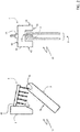
Figure 2 shows different schematic views of an electric pole of the switching apparatus, according to some embodiments of the invention; -
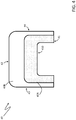
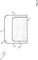
Figure 3-5 schematically shows an arc-breaking plate of an arc-breaking assembly included in the electric poles of the switching apparatus, according to different embodiments of the invention; -
Figures 6-8 schematically show the behavior of an arc-breaking plate included in an arc-breaking assembly of the switching apparatus, according to the invention. - With reference to the attached figures, the present invention relates to a
switching apparatus 1 for electric power distribution grids. - The
switching apparatus 1 is particularly adapted for AC medium-voltage electric systems and it will be described with particular reference to this kind of applications. However, in principle, it may be used also in electric systems of different types, e.g. DC medium-voltage electric systems or low-voltage electric systems. - For the purposes of the present invention, the term "low voltage" (LV) relates to operating voltages lower than 1 kV AC and 1.5 kV DC whereas the term "medium voltage" (MV) relates to operating voltages higher than 1 kV up to some tens of kV, e.g. 70 kV AC and 100 kV DC.
-
Figure 1 shows a schematic view theswitching apparatus 1. - The
switching apparatus 1 comprises one or moreelectric poles 10, each comprising a pair ofpole contacts corresponding line conductors electric line 50. - The
line conductors electric line 50 are, in turn, electrically connectable to an equivalent electric power source (e.g. an electric power feeding or generation system or a section of electric grid) and to an equivalent electric load (e.g. an electric system or apparatus or a section of electric grid). - The number of
electric poles 10 of theswitching apparatus 1 may vary, according to the needs. In the embodiments shown in the cited figures, theswitching apparatus 1 is of the three-phase type and it comprises three-electric poles. However, according to other embodiments of the invention (not shown), theswitching apparatus 1 may include a different number of electric poles depending on the number of electric phases of theelectric line 50. - According to the invention, the
switching apparatus 1 comprises, for eachelectric pole 10, at least a pair ofelectric contacts - In particular, the
switching apparatus 1 comprises, for eachelectric pole 10, at least a fixedcontact 2 and at least amovable contact 3. - According to some embodiments of the invention (
figure 2 ), theswitching apparatus 1 comprises, for eachelectric pole 10, a single fixed contact and a single movable contact that can be mutually coupled or decoupled (single current breaking configuration). - According to other embodiments of the invention (not shown), the
switching apparatus 1 comprises, for eachelectric pole 10, a pair of fixed contacts and a pair of movable contacts that can be mutually coupled or decoupled (double current breaking configuration). - Each
movable contact 3 of the switching apparatus is reversibly movable between a coupled position, at which it is coupled with the correspondingfixed contact 2, and an uncoupled position, at which it is separated from the correspondingfixed contact 2. - When each movable 3 is in a coupled position, the
switching apparatus 1 is in a closed state and line currents can flow along theelectric poles 10 whereas, when each movable 3 is in an uncoupled position, theswitching apparatus 1 is in an open state and no line currents can flow along theelectric poles 10. - A transition from a closed state to the open state forms an opening manoeuvre of the
switching apparatus 1 whereas a transition from an open state to a closed state forms a closing manoeuvre of theswitching apparatus 1. - According to some embodiments of the invention (
figure 2 ), eachmovable contact 3 reversibly moves between the above-mentioned coupled and uncoupled positions by carrying out suitable opposite rotational movements. - According to other embodiments of the invention (not shown), each
movable contact 3 reversibly moves the above-mentioned coupled and uncoupled positions by carrying out suitable opposite linear movements. - Conveniently, the
switching apparatus 1 comprises actuating means (not shown) operatively coupled with themovable contacts 3 through suitable motion transmission means (not shown) and adapted to actuate said movable contacts during an opening or closing manoeuvre. - In general, the
electric contacts apparatus 1 may be realized according to solutions of known type and they will be described hereinafter in relation to the aspects of interest of the invention only, for the sake of brevity. - Besides, the
switching apparatus 1 may comprise a variety of additional components (most of them are not shown in the cited figures), which may be realized according to solutions of known type. Also, these additional components will be not described hereinafter, for the sake of brevity. - The
switching apparatus 1 comprises, for eachelectric pole 10, an arc-breakingassembly 4. - The arc-breaking
assembly 4 comprises a plurality of arc-breakingplates 40 arranged in proximity of theelectric contacts - The arc-breaking
plates 40 are conveniently stacked side by side and spaced one from another along a given stack direction that is conveniently oriented according to the trajectory followed by themovable contact 3 during the manoeuvres of the switching apparatus. - The arc-breaking
plates 40 are thus arranged at positions having increasing relative distances with respect to the fixedcontact 2. - In principle, the arc-
breaking plates 40 may be shaped according to the needs. - As an example, each arc-breaking plate may have a rectangular shape (with rounded edges).
- Preferably (
figure 3 ), the arc-breakingplates 40 comprise opposite a first (bottom) side and a second (top)side - Preferably, the arc-breaking plates have a rectangular shape, in which the opposite first and
second sides fourth sides - Preferably, the first and
second sides plates 40 are respectively in a proximal position and in a distal position with respect to themovable contact 3, in particular during a manoeuvre of the switching apparatus. - Preferably (
figures 3 and4 ), at theirfirst side 41, the arc-breakingplates 40 comprises agroove 410 through which themovable contact 3 passes, during a manoeuvre of the switching apparatus. In practice, when a manoeuvre is carried out, themovable contact 3 passes in proximity of the arc-breakingplates 40 through a channel formed by the alignedgrooves 410. Such a solution is particularly useful to favor the diversion of electric arcs towards the arc-breakingplates 40 and the splitting of said electric arcs in arc segments once they have reached the arc-breaking plates. - The shape of the
grove 410 may be any according to the needs, e.g. rectangular with rounded edges as shown in the cited figures. - Preferably, the arc-breaking
assembly 4 comprises one or moreinsulating support elements 45 operatively coupled with the arc-breaking plates 40 (e.g. at theirsecond side 42 or at their third andfourth sides 43, 44). Conveniently, the insulatingsupport elements 45 maintain the arc-breakingplates 40 in their stacked position and are fixable to a support (not shown) of the correspondingelectric pole 10. - Preferably, the arc-breaking
plates 40 are electrically disconnected from theelectric contacts electric pole 10 and from other live parts of said electric pole. Therefore, they are normally at a floating voltage potential during the operation of the switching apparatus. Preferably, theswitching apparatus 1 is of the gas-insulated type, e.g. a gas-insulated medium-voltage circuit breaker. In this case, eachelectric pole 10 conveniently comprises an arc chamber (not shown) having an internal volume, in which the fixedcontact 2, themovable contact 3 and the arc-breaking assembly are accommodated. - Preferably, such an arc chamber is filled with an insulating gas, for example SF6. However, said arc chamber may be filled with a more environment-friendly insulating gas.
- For example, it may be used an insulating gas selected in a group including CO2, O2, N2, H2, air, N2O, a hydrocarbon compound (in particular CH4), a perfluorinated compound, a partially hydrogenated organofluorine compound, or mixture products thereof.
- As another example, it may be used an insulating gas including a background gas selected in a group including CO2, O2, N2, H2, air, in a mixture with an organofluorine compound selected in a group including fluoroether, oxirane, fluoramine, fluoroketone, fluoroolefin, fluoronitrile, and mixture and/or decomposition products thereof.
- According to the invention, the arc-breaking
plates 40 comprise afirst portion 40A made of a ferromagnetic material and asecond portion 40B made of a metallic non-ferromagnetic material. - Preferably, the above-mentioned ferromagnetic material is a metallic material (e.g. mild steel, cobalt, nickel, iron and the like) optionally coated with an additional material, for example a material (like copper) having an improved electric conductivity.
- The above-mentioned non-ferromagnetic material is a metallic material, e.g. copper, stainless steel, brass, aluminum, and the like.
- According to the invention, the
first portion 40A of ferromagnetic material and the second portion ofnon-ferromagnetic material 40B of the arc-breakingplates 40 are respectively in a proximal position and in a distal position with respect to themovable contact 3, in particular during a manoeuvre of said switching apparatus. - In practice, the
first portion 40A of ferromagnetic material and the second portion ofnon-ferromagnetic material 40B of the arc-breakingplates 40 are relatively positioned one to another in such a way that themovable contact 3 passes closer to thefirst portion 40A, during a manoeuvre of said switching apparatus. - Provided that they are arranged as illustrate above, the
first portion 40A of ferromagnetic material and the second portion ofnon-ferromagnetic material 40B of the arc-breakingplates 40 may have a variety of shapes, according to the needs. - Conveniently, the
first portion 40A of ferromagnetic material of the arc-breakingplates 40 is configured so as to include at least a portion of thefirst side 41 of the arc-breaking plates. - According to some embodiments of the invention, the ferromagnetic
first portion 40A of the arc-breakingplates 40 is configured so as to include thefirst side 41 of the arc-breaking plates and at least a portion of the third andfourth sides - Preferably, when the arc-breaking plates are provided with a
groove 410, the ferromagneticfirst portion 40A and the non-ferromagneticsecond portion 40B are arranged respectively in a proximal position and in a distal position with respect to said groove. - Preferably, the ferromagnetic
first portion 40A is configured so as to surround thegroove 410 of the arc-breaking plates. - Preferably, the non-ferromagnetic
second portion 40B includes the regions of the arc-breakingplates 40, which are not part of the ferromagneticfirst portion 40A. - Preferably, the second
non-ferromagnetic portion 40B is configured so as to surround thefirst portion 40A of ferromagnetic material. -
Figure 3 shows an example of arc-breakingplate 40, according to the invention. The arc-breakingplate 40 comprises agroove 410 at thefirst side 40A. In this case, the ferromagneticfirst portion 40A surrounds thegroove 410 and it comprises the wholefirst side 41 and a portion of the third andfourth sides second portion 40B includes the complementary region of the arc-breakingplate 40, in particular the remaining portions of the third andfourth sides second side 42. The first andsecond portions plate 40 are separated by a boundary. Infigure 3 , such a boundary is shown as a rectilinear. However, in principle, it may have shapes of different type, according to the needs. -
Figure 4 shows another example of arc-breakingplate 40, according to the invention. The arc-breakingplate 40 comprises agroove 410 at thefirst side 40A. The ferromagneticfirst portion 40A surrounds thegroove 410 and it comprises only a portion of the first side 41 (namely the portion defining the groove 410). The secondnon-ferromagnetic portion 40B includes the complementary region of the arc-breakingplate 40, in particular the remaining portions of thefirst side 41 and the whole third andfourth sides second portions plate 40 are separated by a boundary following the profile of thegroove 410. -
Figure 5 shows another example of arc-breakingplate 40, according to the invention. In this case, the arc-breakingplate 40 has no grooves at thefirst side 40A. The ferromagneticfirst portion 40A comprises only a portion of thefirst side 41. The secondnon-ferromagnetic portion 40B includes the complementary region of the arc-breaking plate, in particular the remaining portions of thefirst side 41 and the whole third andfourth sides second portions plates 40 are separated by a curved boundary. - As the skilled person will certainly appreciate, further configurations of the ferromagnetic and
non-ferromagnetic portions plates 40 are possible, provided that they are respectively in a proximal position and in a distal position with respect to themovable contact 3, during a manoeuvre of said switching apparatus. - The operating principle of the invention during an opening manoeuvre of the
switching apparatus 1 is now described referring tofigures 6-8 . -
Figure 6 shows an example of arc-breakingplate 40 according to the invention. - During an opening manoeuvre of the
switching apparatus 1, when themovable contact 3 separates from the fixedcontact 2, an electric arc arises between theelectric contacts electric contacts movable contact 3. - When the
movable contact 3 passes in proximity of the arc-breakingplates 40, the electric arc is attracted in the gaps between the arc-breaking plates, since the ferromagneticfirst portion 40A of each arc-breakingplate 40 is subject to magnetization. The electric arc undergoes splitting into different arc segments between the arc-breaking plates. - Electric arc segments involving an arc-breaking
plate 40 are however subject to additional forces due the current distribution in the splitter plate. - Initially, they are subject to a net resulting Lorentz force FL1 directed in such a way to push them towards the
second side 42 of said arc-breaking plate. Therefore, they move towards thesecond side 42 of the arc-breaking plate until they come in proximity of the boundary between the ferromagneticfirst portion 40A and the non-ferromagneticsecond portion 40B of the arc-breakingplate 40. - In this situation, electric arc segments are subject to a net resulting Lorentz force FL2 directed in such a way to push them away from the
second side 42 of the arc-breaking plate. Therefore, they are kept confined in the ferromagneticfirst portion 40A and they cannot reach thesecond side 42 in distal position from themovable contact 3. - Bridging phenomena of electric arc segments at the
second side 42 of the arc-breakingplate 40 are therefore prevented. - In the embodiments of the invention shown in
figures 4-5 , bridging phenomena of electric arc segments at the third andfourth sides plate 40 are prevented as well, for similar reasons. -
Figure 7 shows some simulation results about the behavior of the arc-breakingplate 40 offigure 6 , during an opening manoeuvre of the switching apparatus. -
Figure 7 includes a plot indicative of spatial distribution of the net resulting Lorentz force (calculated as algebraic sum of its components of opposite sign) as a function of the distance z from thefirst side 41 of the arc-breaking plate 40 (a main longitudinal axis A of said arc-breaking plate is taken as a reference). - The net resulting Lorentz force takes positive (reference is made to the oriented abscissas axis z) values (FL1) in proximity of the
first side 41 of the arc-breaking plate 40 (thefirst side 41 is part of the ferromagneticfirst portion 40A). The net resulting Lorentz is oriented in such a way to push electric arcs towards thesecond side 42 of the arc-breakingplate 40. - By moving from the
first side 41 towards thesecond side 42, the net resulting Lorentz force progressively decreases and it takes negative values (FL2) in proximity of the boundary (distance z1) between the ferromagnetic and non-ferromagnetic portions first side 41 of the arc-breakingplate 40. - The net resulting Lorentz force reaches a negative peak at the boundary between the first and
second portions second side 42, it still takes negative values in proximity of said boundary. - By moving again towards the
second side 42 of the arc-breaking plate, the net resulting Lorentz force progressively increases and it takes again positive values in proximity of thesecond side 42. - It is evident from the above how the net resulting Lorentz force takes negative values FL2 in a neighbourhood of the boundary (distance z2) between the ferromagnetic and
non-ferromagnetic portions portions first side 41 of the arc-breaking plate are thus forced to remain confined withinfirst portion 40A without further moving towards thesecond side 42 of the arc-breaking plate. -
Figure 7 includes a plot indicative of the distribution of the potential energy as a function of the distance z from thefirst side 41 of the arc-breakingplate 40, along the main longitudinal axis A of said arc-breaking plate. - By moving from the
first side 41 towards the non-ferromagneticsecond portion 40B of the arc-breaking plate, the potential energy progressively decreases and it takes a minimum value in proximity of the boundary between the first andsecond portions - This is a further confirmation that possible electric arcs coming from the
first side 41 of the arc-breaking plate are forced to remain confined within the ferromagneticfirst portion 40A without further moving towards thesecond side 42 of the arc-breaking plate. Besides the presence of a potential energy minimum suggests that possible electric arcs will be confined station in proximity of the boundary between the first andsecond portions -
Figure 8 shows some test results about the behavior of the arc-breakingplate 40 offigure 6 , during an opening manoeuvre of the switching apparatus. - In
figure 8 , the foot-prints of the electric arcs affecting the arc-breaking plate during an opening manoeuvre of the switching apparatus are clearly visible. This experimental evidence clearly proves how electric arcs are confined in theferromagnetic region 40A in proximity of the boundary with thenon-ferromagnetic region 40B without moving towards thesecond side 42, as it was predictable by observing the plots offigure 7 . - The
switching apparatus 1, according to the invention, provides relevant advantages with respect to corresponding known switching systems of the state of the art. - The
switching apparatus 1 is provided with an arc-breakingassembly 4 having improved current breaking capabilities. - The arrangement of arc-breaking
plates 40 including adjacent ferromagnetic andnon-ferromagnetic regions 40A-40B, which are relatively positioned as illustrated above, allows preventing or remarkably reducing possible bridging phenomena at thetop side 42 of said arc-breaking plates during an opening manoeuvre of the switching apparatus. - Electric arcs are forced to station at the
ferromagnetic region 40A of the arc-breakingplates 40 thereby resulting confined in the gap between each pair of adjacent arc-breaking plates. This allows fully exploiting the quenching action (arc segmentation) provided by the arc-breaking plates. - In addition to the advantages above, the arrangement of arc-breaking
plates 40 with anon-ferromagnetic region 40B allows cooling down the insulating gas between said arc-breaking plates, thereby improving the dielectric properties of said insulating gas (it becomes less conductive) and preventing the formation of decomposition products. -
Arc breaking plates 40 may be easily manufactured at industrial level with traditional metallurgic techniques, e.g. suitable moulding processes. - The
switching apparatus 1 is relatively easy and cheap to manufacture at industrial level with well-established manufacturing techniques. It may therefore be manufactured at competitive costs with similar switching systems of the state of the art. - The
switching apparatus 1 is particularly adapted for use in AC medium-voltage applications. However, it may be conveniently used also in applications of different type.
Claims (11)
- A switching apparatus (1) for electric power distribution grids comprising:- one or more electric poles (10);- for each electric pole, at least a fixed contact (2) and a movable contact (3), said movable contact being reversibly movable between a coupled position, at which said movable contact is coupled with said fixed contact, and an uncoupled position, at which said movable contact is separated from said fixed contact;- for each electric pole, an arc-breaking assembly (4) comprising a plurality of arc-breaking plates (40);characterised in that said arc-breaking plates (40) comprise a first portion (40A) made of a ferromagnetic material and a second portion (40B) made of a metallic non-ferromagnetic material, wherein the first portion (40A) and the second portion (40B) of said arc-breaking plates are arranged so as to be respectively in a proximal position and in a distal position with respect to said movable contact (3), during a manoeuvre of said switching apparatus.
- Switching apparatus, according to claim 1, characterised in that said arc-breaking plates (40) comprise opposite first and second sides (41, 42) defining a first dimension (L) of said arc-breaking plates and opposite third and fourth sides defining a second dimension (W) of said arc-breaking plates, wherein the first and second sides (41, 42) of said arc-breaking plates are arranged so as to be respectively in a proximal position and in a distal position with respect to said movable contact (3), during a manoeuvre of said switching apparatus.
- Switching apparatus, according to claim 2, characterised in that said arc-breaking plates (40) comprise, at said first side (41), a groove (410) through which said movable contact (3) passes, during a manoeuvre of said switching apparatus.
- Switching apparatus, according to one or more of the previous claims, characterised in that the first portion (40A) of said arc-breaking plates (40) is configured so as to include at least a portion of the first side (41) of said arc-breaking plates.
- Switching apparatus, according to claim 4, characterised in that the first portion (40A) of said arc-breaking plates (40) is configured so as to include the first side (41) and at least a portion of the third and fourth sides (43, 44) of said arc-breaking plates.
- Switching apparatus, according to one of the claims from 3 to 5, characterised in that the first and second portions (40A, 40B) of said arc-breaking plates are arranged respectively in a proximal position and in a distal position with respect to said groove (410).
- Switching apparatus, according to claim 6, characterised in that the first portion (40A) of said arc-breaking plates is configured so as to surround the groove (410) of said arc-breaking plates.
- Switching apparatus, according to one of the claims from 4 to 7, characterised in that the second portion (40B) of said arc-breaking plates (40) is configured so as to surround the first portion (40A) of said arc-breaking plates (40)
- A switching apparatus, according to one or more of the previous claims, characterised in that it comprises, for each electric pole, an arc chamber (5) including said fixed contact (2), said movable contact (3) and said arc-breaking assembly (4), said arc chamber being filled with an insulating gas.
- A switching apparatus, according to one or more of the previous claims, characterised in that it is a medium-voltage circuit breaker.
- A medium-voltage electric system comprising a switching apparatus (1), according to one or more of the previous claims.
Priority Applications (1)
| Application Number | Priority Date | Filing Date | Title |
|---|---|---|---|
| EP20174616.1A EP3910657B1 (en) | 2020-05-14 | 2020-05-14 | A switching apparatus for electric power distribution grids |
Applications Claiming Priority (1)
| Application Number | Priority Date | Filing Date | Title |
|---|---|---|---|
| EP20174616.1A EP3910657B1 (en) | 2020-05-14 | 2020-05-14 | A switching apparatus for electric power distribution grids |
Publications (2)
| Publication Number | Publication Date |
|---|---|
| EP3910657A1 true EP3910657A1 (en) | 2021-11-17 |
| EP3910657B1 EP3910657B1 (en) | 2023-01-18 |
Family
ID=70736679
Family Applications (1)
| Application Number | Title | Priority Date | Filing Date |
|---|---|---|---|
| EP20174616.1A Active EP3910657B1 (en) | 2020-05-14 | 2020-05-14 | A switching apparatus for electric power distribution grids |
Country Status (1)
| Country | Link |
|---|---|
| EP (1) | EP3910657B1 (en) |
Citations (3)
| Publication number | Priority date | Publication date | Assignee | Title |
|---|---|---|---|---|
| WO2011147458A1 (en) * | 2010-05-28 | 2011-12-01 | Abb Research Ltd | A dc switching device |
| CN105405707B (en) * | 2015-12-03 | 2018-04-03 | 上海天灵开关厂有限公司 | Gas insulated load switch and its arc-control device |
| US10483068B1 (en) * | 2018-12-11 | 2019-11-19 | Eaton Intelligent Power Limited | Switch disconnector systems suitable for molded case circuit breakers and related methods |
-
2020
- 2020-05-14 EP EP20174616.1A patent/EP3910657B1/en active Active
Patent Citations (3)
| Publication number | Priority date | Publication date | Assignee | Title |
|---|---|---|---|---|
| WO2011147458A1 (en) * | 2010-05-28 | 2011-12-01 | Abb Research Ltd | A dc switching device |
| CN105405707B (en) * | 2015-12-03 | 2018-04-03 | 上海天灵开关厂有限公司 | Gas insulated load switch and its arc-control device |
| US10483068B1 (en) * | 2018-12-11 | 2019-11-19 | Eaton Intelligent Power Limited | Switch disconnector systems suitable for molded case circuit breakers and related methods |
Also Published As
| Publication number | Publication date |
|---|---|
| EP3910657B1 (en) | 2023-01-18 |
Similar Documents
| Publication | Publication Date | Title |
|---|---|---|
| AU2011253907B2 (en) | Single direct current arc chamber, and bi-directional direct current electrical switching apparatus employing the same | |
| DE102013114260A1 (en) | Double contact switch with vacuum interrupters | |
| CA3040399C (en) | Electrical interruption device | |
| US9502195B2 (en) | Switching device | |
| US9543086B2 (en) | Power circuit breaker | |
| MXPA97007781A (en) | Electrical current switch apparatus with arc tornad extinguishing mechanism | |
| US20190198278A1 (en) | High voltage compact fused disconnect switch device with bi-directional magnetic arc deflection assembly | |
| EP3910657B1 (en) | A switching apparatus for electric power distribution grids | |
| EP3910658A1 (en) | A switching apparatus for electric power distribution grids | |
| EP3933866B1 (en) | A switching apparatus for electric power distribution grids | |
| US11688570B2 (en) | Switching device | |
| CN113196432B (en) | Electrical switch system | |
| CN216435773U (en) | Contact system, circuit breaker and isolator with increase magnetic component | |
| EP4300529B1 (en) | Medium voltage or high voltage switch system with a magnetic system applying a transverse field to a vacuum switch | |
| RU214912U1 (en) | Magnetic contactor | |
| EP4089704B1 (en) | A medium voltage switching apparatus | |
| CN219778737U (en) | Arc extinguishing system capable of pulling arc to move by external magnetic field and circuit breaker | |
| EP4738409A1 (en) | Switchgear, method and use | |
| CN223108763U (en) | breaker | |
| EP4435815A1 (en) | A switching apparatus for medium voltage electrical systems | |
| CN116313678A (en) | A bidirectional non-polar DC arc extinguishing system and miniature circuit breaker | |
| EP4089705A1 (en) | A medium voltage switching apparatus | |
| JP4693736B2 (en) | Gas insulated disconnect switch | |
| CN120833986A (en) | Switchgear for electrical systems | |
| EP3073501A1 (en) | Multipole lineal switch |
Legal Events
| Date | Code | Title | Description |
|---|---|---|---|
| PUAI | Public reference made under article 153(3) epc to a published international application that has entered the european phase |
Free format text: ORIGINAL CODE: 0009012 |
|
| STAA | Information on the status of an ep patent application or granted ep patent |
Free format text: STATUS: THE APPLICATION HAS BEEN PUBLISHED |
|
| AK | Designated contracting states |
Kind code of ref document: A1 Designated state(s): AL AT BE BG CH CY CZ DE DK EE ES FI FR GB GR HR HU IE IS IT LI LT LU LV MC MK MT NL NO PL PT RO RS SE SI SK SM TR |
|
| B565 | Issuance of search results under rule 164(2) epc |
Effective date: 20201102 |
|
| STAA | Information on the status of an ep patent application or granted ep patent |
Free format text: STATUS: REQUEST FOR EXAMINATION WAS MADE |
|
| 17P | Request for examination filed |
Effective date: 20220509 |
|
| RBV | Designated contracting states (corrected) |
Designated state(s): AL AT BE BG CH CY CZ DE DK EE ES FI FR GB GR HR HU IE IS IT LI LT LU LV MC MK MT NL NO PL PT RO RS SE SI SK SM TR |
|
| GRAP | Despatch of communication of intention to grant a patent |
Free format text: ORIGINAL CODE: EPIDOSNIGR1 |
|
| STAA | Information on the status of an ep patent application or granted ep patent |
Free format text: STATUS: GRANT OF PATENT IS INTENDED |
|
| INTG | Intention to grant announced |
Effective date: 20220909 |
|
| RIN1 | Information on inventor provided before grant (corrected) |
Inventor name: ABPLANALP, MARKUS Inventor name: LANTZ, GABRIEL Inventor name: RAGER, FELIX Inventor name: BABOU, YACINE Inventor name: RANJAN, NITESH |
|
| GRAS | Grant fee paid |
Free format text: ORIGINAL CODE: EPIDOSNIGR3 |
|
| GRAA | (expected) grant |
Free format text: ORIGINAL CODE: 0009210 |
|
| STAA | Information on the status of an ep patent application or granted ep patent |
Free format text: STATUS: THE PATENT HAS BEEN GRANTED |
|
| AK | Designated contracting states |
Kind code of ref document: B1 Designated state(s): AL AT BE BG CH CY CZ DE DK EE ES FI FR GB GR HR HU IE IS IT LI LT LU LV MC MK MT NL NO PL PT RO RS SE SI SK SM TR |
|
| REG | Reference to a national code |
Ref country code: GB Ref legal event code: FG4D |
|
| REG | Reference to a national code |
Ref country code: CH Ref legal event code: EP |
|
| REG | Reference to a national code |
Ref country code: DE Ref legal event code: R096 Ref document number: 602020007618 Country of ref document: DE |
|
| REG | Reference to a national code |
Ref country code: AT Ref legal event code: REF Ref document number: 1545143 Country of ref document: AT Kind code of ref document: T Effective date: 20230215 Ref country code: IE Ref legal event code: FG4D |
|
| REG | Reference to a national code |
Ref country code: LT Ref legal event code: MG9D |
|
| REG | Reference to a national code |
Ref country code: NL Ref legal event code: MP Effective date: 20230118 |
|
| REG | Reference to a national code |
Ref country code: AT Ref legal event code: MK05 Ref document number: 1545143 Country of ref document: AT Kind code of ref document: T Effective date: 20230118 |
|
| PG25 | Lapsed in a contracting state [announced via postgrant information from national office to epo] |
Ref country code: NL Free format text: LAPSE BECAUSE OF FAILURE TO SUBMIT A TRANSLATION OF THE DESCRIPTION OR TO PAY THE FEE WITHIN THE PRESCRIBED TIME-LIMIT Effective date: 20230118 |
|
| PG25 | Lapsed in a contracting state [announced via postgrant information from national office to epo] |
Ref country code: RS Free format text: LAPSE BECAUSE OF FAILURE TO SUBMIT A TRANSLATION OF THE DESCRIPTION OR TO PAY THE FEE WITHIN THE PRESCRIBED TIME-LIMIT Effective date: 20230118 Ref country code: PT Free format text: LAPSE BECAUSE OF FAILURE TO SUBMIT A TRANSLATION OF THE DESCRIPTION OR TO PAY THE FEE WITHIN THE PRESCRIBED TIME-LIMIT Effective date: 20230518 Ref country code: NO Free format text: LAPSE BECAUSE OF FAILURE TO SUBMIT A TRANSLATION OF THE DESCRIPTION OR TO PAY THE FEE WITHIN THE PRESCRIBED TIME-LIMIT Effective date: 20230418 Ref country code: LV Free format text: LAPSE BECAUSE OF FAILURE TO SUBMIT A TRANSLATION OF THE DESCRIPTION OR TO PAY THE FEE WITHIN THE PRESCRIBED TIME-LIMIT Effective date: 20230118 Ref country code: LT Free format text: LAPSE BECAUSE OF FAILURE TO SUBMIT A TRANSLATION OF THE DESCRIPTION OR TO PAY THE FEE WITHIN THE PRESCRIBED TIME-LIMIT Effective date: 20230118 Ref country code: HR Free format text: LAPSE BECAUSE OF FAILURE TO SUBMIT A TRANSLATION OF THE DESCRIPTION OR TO PAY THE FEE WITHIN THE PRESCRIBED TIME-LIMIT Effective date: 20230118 Ref country code: ES Free format text: LAPSE BECAUSE OF FAILURE TO SUBMIT A TRANSLATION OF THE DESCRIPTION OR TO PAY THE FEE WITHIN THE PRESCRIBED TIME-LIMIT Effective date: 20230118 Ref country code: AT Free format text: LAPSE BECAUSE OF FAILURE TO SUBMIT A TRANSLATION OF THE DESCRIPTION OR TO PAY THE FEE WITHIN THE PRESCRIBED TIME-LIMIT Effective date: 20230118 |
|
| PG25 | Lapsed in a contracting state [announced via postgrant information from national office to epo] |
Ref country code: SE Free format text: LAPSE BECAUSE OF FAILURE TO SUBMIT A TRANSLATION OF THE DESCRIPTION OR TO PAY THE FEE WITHIN THE PRESCRIBED TIME-LIMIT Effective date: 20230118 Ref country code: PL Free format text: LAPSE BECAUSE OF FAILURE TO SUBMIT A TRANSLATION OF THE DESCRIPTION OR TO PAY THE FEE WITHIN THE PRESCRIBED TIME-LIMIT Effective date: 20230118 Ref country code: IS Free format text: LAPSE BECAUSE OF FAILURE TO SUBMIT A TRANSLATION OF THE DESCRIPTION OR TO PAY THE FEE WITHIN THE PRESCRIBED TIME-LIMIT Effective date: 20230518 Ref country code: GR Free format text: LAPSE BECAUSE OF FAILURE TO SUBMIT A TRANSLATION OF THE DESCRIPTION OR TO PAY THE FEE WITHIN THE PRESCRIBED TIME-LIMIT Effective date: 20230419 Ref country code: FI Free format text: LAPSE BECAUSE OF FAILURE TO SUBMIT A TRANSLATION OF THE DESCRIPTION OR TO PAY THE FEE WITHIN THE PRESCRIBED TIME-LIMIT Effective date: 20230118 |
|
| REG | Reference to a national code |
Ref country code: DE Ref legal event code: R097 Ref document number: 602020007618 Country of ref document: DE |
|
| PG25 | Lapsed in a contracting state [announced via postgrant information from national office to epo] |
Ref country code: SM Free format text: LAPSE BECAUSE OF FAILURE TO SUBMIT A TRANSLATION OF THE DESCRIPTION OR TO PAY THE FEE WITHIN THE PRESCRIBED TIME-LIMIT Effective date: 20230118 Ref country code: RO Free format text: LAPSE BECAUSE OF FAILURE TO SUBMIT A TRANSLATION OF THE DESCRIPTION OR TO PAY THE FEE WITHIN THE PRESCRIBED TIME-LIMIT Effective date: 20230118 Ref country code: EE Free format text: LAPSE BECAUSE OF FAILURE TO SUBMIT A TRANSLATION OF THE DESCRIPTION OR TO PAY THE FEE WITHIN THE PRESCRIBED TIME-LIMIT Effective date: 20230118 Ref country code: DK Free format text: LAPSE BECAUSE OF FAILURE TO SUBMIT A TRANSLATION OF THE DESCRIPTION OR TO PAY THE FEE WITHIN THE PRESCRIBED TIME-LIMIT Effective date: 20230118 Ref country code: CZ Free format text: LAPSE BECAUSE OF FAILURE TO SUBMIT A TRANSLATION OF THE DESCRIPTION OR TO PAY THE FEE WITHIN THE PRESCRIBED TIME-LIMIT Effective date: 20230118 |
|
| PLBE | No opposition filed within time limit |
Free format text: ORIGINAL CODE: 0009261 |
|
| STAA | Information on the status of an ep patent application or granted ep patent |
Free format text: STATUS: NO OPPOSITION FILED WITHIN TIME LIMIT |
|
| PG25 | Lapsed in a contracting state [announced via postgrant information from national office to epo] |
Ref country code: SK Free format text: LAPSE BECAUSE OF FAILURE TO SUBMIT A TRANSLATION OF THE DESCRIPTION OR TO PAY THE FEE WITHIN THE PRESCRIBED TIME-LIMIT Effective date: 20230118 |
|
| 26N | No opposition filed |
Effective date: 20231019 |
|
| REG | Reference to a national code |
Ref country code: CH Ref legal event code: PL |
|
| PG25 | Lapsed in a contracting state [announced via postgrant information from national office to epo] |
Ref country code: MC Free format text: LAPSE BECAUSE OF FAILURE TO SUBMIT A TRANSLATION OF THE DESCRIPTION OR TO PAY THE FEE WITHIN THE PRESCRIBED TIME-LIMIT Effective date: 20230118 |
|
| REG | Reference to a national code |
Ref country code: BE Ref legal event code: MM Effective date: 20230531 |
|
| PG25 | Lapsed in a contracting state [announced via postgrant information from national office to epo] |
Ref country code: SI Free format text: LAPSE BECAUSE OF FAILURE TO SUBMIT A TRANSLATION OF THE DESCRIPTION OR TO PAY THE FEE WITHIN THE PRESCRIBED TIME-LIMIT Effective date: 20230118 Ref country code: MC Free format text: LAPSE BECAUSE OF FAILURE TO SUBMIT A TRANSLATION OF THE DESCRIPTION OR TO PAY THE FEE WITHIN THE PRESCRIBED TIME-LIMIT Effective date: 20230118 Ref country code: LU Free format text: LAPSE BECAUSE OF NON-PAYMENT OF DUE FEES Effective date: 20230514 Ref country code: LI Free format text: LAPSE BECAUSE OF NON-PAYMENT OF DUE FEES Effective date: 20230531 Ref country code: CH Free format text: LAPSE BECAUSE OF NON-PAYMENT OF DUE FEES Effective date: 20230531 |
|
| REG | Reference to a national code |
Ref country code: IE Ref legal event code: MM4A |
|
| PG25 | Lapsed in a contracting state [announced via postgrant information from national office to epo] |
Ref country code: IE Free format text: LAPSE BECAUSE OF NON-PAYMENT OF DUE FEES Effective date: 20230514 |
|
| PG25 | Lapsed in a contracting state [announced via postgrant information from national office to epo] |
Ref country code: IE Free format text: LAPSE BECAUSE OF NON-PAYMENT OF DUE FEES Effective date: 20230514 |
|
| PG25 | Lapsed in a contracting state [announced via postgrant information from national office to epo] |
Ref country code: IT Free format text: LAPSE BECAUSE OF FAILURE TO SUBMIT A TRANSLATION OF THE DESCRIPTION OR TO PAY THE FEE WITHIN THE PRESCRIBED TIME-LIMIT Effective date: 20230118 Ref country code: BE Free format text: LAPSE BECAUSE OF NON-PAYMENT OF DUE FEES Effective date: 20230531 |
|
| PG25 | Lapsed in a contracting state [announced via postgrant information from national office to epo] |
Ref country code: BG Free format text: LAPSE BECAUSE OF FAILURE TO SUBMIT A TRANSLATION OF THE DESCRIPTION OR TO PAY THE FEE WITHIN THE PRESCRIBED TIME-LIMIT Effective date: 20230118 |
|
| PG25 | Lapsed in a contracting state [announced via postgrant information from national office to epo] |
Ref country code: BG Free format text: LAPSE BECAUSE OF FAILURE TO SUBMIT A TRANSLATION OF THE DESCRIPTION OR TO PAY THE FEE WITHIN THE PRESCRIBED TIME-LIMIT Effective date: 20230118 |
|
| GBPC | Gb: european patent ceased through non-payment of renewal fee |
Effective date: 20240514 |
|
| PG25 | Lapsed in a contracting state [announced via postgrant information from national office to epo] |
Ref country code: GB Free format text: LAPSE BECAUSE OF NON-PAYMENT OF DUE FEES Effective date: 20240514 |
|
| PGFP | Annual fee paid to national office [announced via postgrant information from national office to epo] |
Ref country code: DE Payment date: 20250521 Year of fee payment: 6 |
|
| PGFP | Annual fee paid to national office [announced via postgrant information from national office to epo] |
Ref country code: FR Payment date: 20250528 Year of fee payment: 6 |
|
| PG25 | Lapsed in a contracting state [announced via postgrant information from national office to epo] |
Ref country code: CY Free format text: LAPSE BECAUSE OF FAILURE TO SUBMIT A TRANSLATION OF THE DESCRIPTION OR TO PAY THE FEE WITHIN THE PRESCRIBED TIME-LIMIT; INVALID AB INITIO Effective date: 20200514 |
|
| PG25 | Lapsed in a contracting state [announced via postgrant information from national office to epo] |
Ref country code: HU Free format text: LAPSE BECAUSE OF FAILURE TO SUBMIT A TRANSLATION OF THE DESCRIPTION OR TO PAY THE FEE WITHIN THE PRESCRIBED TIME-LIMIT; INVALID AB INITIO Effective date: 20200514 |
|
| PG25 | Lapsed in a contracting state [announced via postgrant information from national office to epo] |
Ref country code: TR Free format text: LAPSE BECAUSE OF FAILURE TO SUBMIT A TRANSLATION OF THE DESCRIPTION OR TO PAY THE FEE WITHIN THE PRESCRIBED TIME-LIMIT Effective date: 20230118 |