EP3910523A1 - Machine learning program, method and device for estimating the electromagnetic wave radiation situation of an electronic circuit - Google Patents
Machine learning program, method and device for estimating the electromagnetic wave radiation situation of an electronic circuit Download PDFInfo
- Publication number
- EP3910523A1 EP3910523A1 EP21163962.0A EP21163962A EP3910523A1 EP 3910523 A1 EP3910523 A1 EP 3910523A1 EP 21163962 A EP21163962 A EP 21163962A EP 3910523 A1 EP3910523 A1 EP 3910523A1
- Authority
- EP
- European Patent Office
- Prior art keywords
- electronic circuit
- resonance frequency
- machine learning
- analyzed
- circuit
- Prior art date
- Legal status (The legal status is an assumption and is not a legal conclusion. Google has not performed a legal analysis and makes no representation as to the accuracy of the status listed.)
- Granted
Links
Images






Classifications
-
- G—PHYSICS
- G06—COMPUTING OR CALCULATING; COUNTING
- G06N—COMPUTING ARRANGEMENTS BASED ON SPECIFIC COMPUTATIONAL MODELS
- G06N3/00—Computing arrangements based on biological models
- G06N3/02—Neural networks
- G06N3/08—Learning methods
- G06N3/084—Backpropagation, e.g. using gradient descent
-
- G—PHYSICS
- G06—COMPUTING OR CALCULATING; COUNTING
- G06N—COMPUTING ARRANGEMENTS BASED ON SPECIFIC COMPUTATIONAL MODELS
- G06N20/00—Machine learning
-
- G—PHYSICS
- G06—COMPUTING OR CALCULATING; COUNTING
- G06F—ELECTRIC DIGITAL DATA PROCESSING
- G06F30/00—Computer-aided design [CAD]
- G06F30/30—Circuit design
- G06F30/36—Circuit design at the analogue level
- G06F30/367—Design verification, e.g. using simulation, simulation program with integrated circuit emphasis [SPICE], direct methods or relaxation methods
-
- G—PHYSICS
- G06—COMPUTING OR CALCULATING; COUNTING
- G06F—ELECTRIC DIGITAL DATA PROCESSING
- G06F30/00—Computer-aided design [CAD]
- G06F30/30—Circuit design
- G06F30/36—Circuit design at the analogue level
- G06F30/373—Design optimisation
-
- G—PHYSICS
- G06—COMPUTING OR CALCULATING; COUNTING
- G06F—ELECTRIC DIGITAL DATA PROCESSING
- G06F30/00—Computer-aided design [CAD]
- G06F30/30—Circuit design
- G06F30/39—Circuit design at the physical level
-
- G—PHYSICS
- G06—COMPUTING OR CALCULATING; COUNTING
- G06F—ELECTRIC DIGITAL DATA PROCESSING
- G06F30/00—Computer-aided design [CAD]
- G06F30/30—Circuit design
- G06F30/39—Circuit design at the physical level
- G06F30/398—Design verification or optimisation, e.g. using design rule check [DRC], layout versus schematics [LVS] or finite element methods [FEM]
-
- G—PHYSICS
- G06—COMPUTING OR CALCULATING; COUNTING
- G06N—COMPUTING ARRANGEMENTS BASED ON SPECIFIC COMPUTATIONAL MODELS
- G06N5/00—Computing arrangements using knowledge-based models
- G06N5/04—Inference or reasoning models
-
- G—PHYSICS
- G06—COMPUTING OR CALCULATING; COUNTING
- G06F—ELECTRIC DIGITAL DATA PROCESSING
- G06F2111/00—Details relating to CAD techniques
- G06F2111/10—Numerical modelling
Definitions
- the embodiment discussed herein is related to a machine learning estimation program, a machine learning estimation method, and an information processing device.
- the electromagnetic wave radiation situation indicates a situation of a far electromagnetic field, and is also referred to as a far field.
- the electromagnetic wave radiation situation is estimated based on an electronic circuit to be analyzed, by using a learning model generated from learning data in which a learning electronic circuit and a simulation result of electromagnetic wave analysis for the electronic circuit are paired.
- a situation of a near electromagnetic field (near field) generated by various values of elements including an inductor (L), a capacitor (C), and a resistor (R) may not be accurately approximated, and thus there is a problem in that it is difficult to accurately estimate a far field in some cases.
- LCR element L, C, and R elements
- the near field may be approximated based on a total length of the respective lines.
- the values of L, C, and R are small and the reflection is small is exactly the same as a case where the LCR element is not present, so that it is difficult to accurately approximate an approximation field.
- an object is to provide an estimation technique which may support accurate estimation of an electromagnetic wave radiation situation.
- a machine learning estimation program causes a computer to execute a process, the process comprising identifying, for an electronic circuit to be analyzed, a resonance frequency of a current and a spatial distribution of the current that flows through the electronic circuit to be analyzed at the resonance frequency, generating a machine learning model using a training data set in which arrangements of circuit elements in respective electronic circuits differ from each other, the training data set being a set of training data in each of which a specific value of a resonance frequency for a specific electronic circuit and information of a spatial distribution of a current that flows through the specific electronic circuit at the resonance frequency of the specific value are used as input data and an electromagnetic wave radiation situation of the specific electronic circuit is set as a label, inputting, as input data, a frequency value of the identified resonance frequency and information of the identified spatial distribution to the generated machine learning model, and estimating an electromagnetic wave radiation situation of the electronic circuit to be analyzed, based on an output from the machine learning model according to the inputting.
- an electromagnetic wave radiation situation in an electronic circuit to be analyzed, will be described.
- One point of interest in the present embodiment is that a far field of electromagnetic wave radiation in the electronic circuit to be analyzed is determined by an approximation field, and a near field is determined by a current flowing through the circuit.
- wiring serves as an antenna to generate an electromagnetic field, and a part of energy of the electromagnetic field is radiated as the EMI.
- An intensity of the electromagnetic field is determined by the amount of current flowing through the wiring. Therefore, the near field may be approximated by using a spatial distribution (hereinafter, also referred to as a current distribution) of the current flowing through the electronic circuit to be analyzed.
- a spatial distribution hereinafter, also referred to as a current distribution
- the current flowing through the electronic circuit differs for each frequency.
- the current distribution has a distribution over the frequency.
- machine learning is performed on a relationship between the current distributions at all frequencies and the EMI intensity, there is a problem in that the number of pieces of data to be learned becomes unrealistic.
- the peak of the EMI spectrum is obtained as a frequency at which a maximum value of the current distribution is the highest.
- a peak frequency is referred to as a resonance frequency.
- another point of interest in the present embodiment is to perform machine learning by focusing on the current distribution at the resonance frequency.
- a value of the resonance frequency of the electronic circuit and the current distribution of the electronic circuit at the resonance frequency are set as feature quantities, and the machine learning is performed on a relationship of the EMI intensity with respect to the feature quantities, so that an estimation model is generated.
- the value of the resonance frequency and the current distribution at the resonance frequency are identified for the electronic circuit to be analyzed, and the value of the identified resonance frequency and the current distribution are input to the estimation model, so that the estimated value of the EMI intensity is obtained based on the output from the estimation model.
- FIG. 1 is an explanatory diagram for explaining an overview of the learning phase and the estimation phase according to the embodiment.
- circuit information in an electronic circuit of each case is acquired from a training data set including cases to be learned in which arrangements of circuit elements in the electronic circuit differ from each other (S1).
- the circuit information includes, for example, information on a circuit network (for example, a network list) of the circuit element (LCR element) included in the electronic circuit, a physical property value (a resistance value, inductance, or electrostatic capacitance) of each circuit element, and the like.
- the current distribution at each frequency in the electronic circuit is calculated by a circuit simulator such as a simulation program with integrated circuit emphasis (SPICE) (S2).
- SPICE simulation program with integrated circuit emphasis
- an output in S2 is an image on which coloring processing is performed such that the color becomes lighter as being far away from lines based on intensity information of the current distribution.
- the output in S2 is information (image information) indicating an intensity of the current distribution that approximates the near field of the electronic circuit.
- the resonance frequency (f1) is input to the estimation model as Ch. 1
- the current distribution at the resonance frequency (f1) is input to the estimation model as Ch. 2.
- the resonance frequency (f2) is input to the estimation model as Ch. 1
- the current distribution at the resonance frequency (f2) is input to the estimation model as Ch. 2.
- parameters of the estimation model are learned (learned by using an error back propagation method) so that the output from the estimation model for the inputs of Ch. 1 and Ch. 2 approaches a correct answer label (EMI intensity) included in the training data set (S5).
- EMI intensity correct answer label
- the circuit information of the electronic circuit to be analyzed is acquired and the processes in S1 to S4 are performed.
- the circuit information in the electronic circuit to be analyzed is acquired by an input from a user, or the like (S1).
- the current distribution at each frequency in the electronic circuit is calculated by the circuit simulator such as SPICE (S2).
- the resonance frequency (f1, f2) at which the maximum value of the calculated current distribution is the highest is identified, and the current distribution for each resonance frequency (f1, f2) is obtained (S3).
- the information on the identified frequency (the value of the resonance frequency) is input as the input data of the channel 1 (Ch. 1), and the information on the current distribution at the frequency (the image indicating the current distribution) is input as the input data of the channel 2 (Ch. 2) to the estimation model such as the deep learning
- the estimated value of the EMI intensity is obtained based on the output from the estimation model (S5).
- FIG. 2 is a block diagram illustrating an example of a functional configuration of the information processing device according to the embodiment.
- the information processing device 1 is a computer that includes a communication unit 10, a storage unit 20, and a control unit 30, and that executes the learning phase and the estimation phase which are described above.
- a personal computer (PC) or the like may be applied to the information processing device 1.
- the information processing device 1 is an example of an estimation device or a model generation device.
- the communication unit 10 communicates with input devices, such as a keyboard and a mouse, and other information processing devices via a LAN, a communication cable, or the like under the control of the control unit 30.
- the information processing device 1 receives, for example, an input of a training data set 21 for training the estimation model and an input of circuit information of the electronic circuit to be analyzed via the communication unit 10.
- the storage unit 20 is, for example, a semiconductor memory element, such as a random-access memory (RAM) or a flash memory, or a storage device such as a hard disk or an optical disk.
- the storage unit 20 includes the training data set 21, estimation model information 22, and estimation result information 23.
- the training data set 21 is a data set of training data including cases to be learned in which the arrangements of the circuit elements in the electronic circuit differ from each other.
- the training data of the training data set 21 includes the circuit information and the correct answer label (EMI intensity) in each case.
- the estimation model information 22 is a parameter or the like for constructing a machine learning model (estimation model) generated by the machine learning.
- the estimation result information 23 is an estimation result obtained by using the estimation model of the estimation model information 22 for the circuit information of the electronic circuit to be analyzed.
- the estimation result information 23 is a value of the EMI intensity for each resonance frequency in the electronic circuit to be analyzed.
- the control unit 30 corresponds to the electronic circuit such as a central processing unit (CPU).
- the control unit 30 includes an internal memory for storing programs defining various processing procedures and control data, and executes various processing by using the programs and the control data.
- control unit 30 includes an input unit 31, an input data creation unit 32, a learning unit 33, and an estimation unit 34.
- the input data creation unit 32 is an example of an identification unit or an acquisition unit.
- the learning unit 33 is an example of a model generation unit.
- the input unit 31 is a processing unit that receives input of various information such as the training data set 21 and the circuit information of the electronic circuit to be analyzed. For example, the input unit 31 stores the training data set 21 input via the communication unit 10 in the storage unit 20. The input unit 31 outputs the circuit information of the electronic circuit to be analyzed input via the communication unit 10 to the input data creation unit 32.
- the input data creation unit 32 is a processing unit that generates the input data to be input to the estimation model. For example, the input data creation unit 32 calculates the current distribution at each frequency in the electronic circuit by the circuit simulator such as SPICE based on the circuit information. Next, the input data creation unit 32 identifies the resonance frequency at which the maximum value of the calculated current distribution is the highest, and identifies the current distribution for each resonance frequency. Next, the input data creation unit 32 generates the input data in which the identified resonance frequency is set to Ch. 1 and the current distribution at the resonance frequency is set to Ch. 2.
- the learning unit 33 is a processing unit that learns the parameters of the estimation model by the machine learning (learning by using the error back propagation method). For example, the learning unit 33 learns the parameters of the estimation model such that the output from the estimation model for the input data (Ch. 1: the value of the resonance frequency, Ch. 2: the current distribution at the resonance frequency) generated by the input data creation unit 32 for the case to be learned approaches the correct answer label (EMI intensity) of the case. Next, the learning unit 33 stores the parameters of the estimation model obtained by the learning in the storage unit 20 as the estimation model information 22.
- the estimation unit 34 is a processing unit that estimates the electromagnetic wave radiation situation in the electronic circuit to be analyzed by using the estimation model generated by the machine learning of the learning unit 33. For example, the estimation unit 34 inputs the input data (Ch. 1: the value of the resonance frequency, Ch. 2: the current distribution at the resonance frequency) generated by the input data creation unit 32 for the electronic circuit to be analyzed to the estimation model based on the estimation model information 22. Next, the estimation unit 34 obtains the estimated value (estimation result) of the EMI intensity based on the output from the estimation model according to the input. Next, the estimation unit 34 stores the obtained estimation result in the storage unit 20 as the estimation result information 23, together with, for example, the electronic circuit to be analyzed.
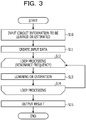
- FIG. 3 is a flowchart illustrating an example of an operation of the information processing device according to the embodiment.
- the input unit 31 receives input of the circuit information to be learned or estimated via the communication unit 10 or the like (S10).
- the input data creation unit 32 creates the input data (Ch. 1: the value of the resonance frequency, Ch. 2: the current distribution at the resonance frequency) to be input to the estimation model (S11).
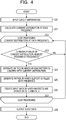
- FIG. 4 is a flowchart illustrating an example of input data generation processing.
- FIG. 5 is an explanatory diagram for explaining an overview of the input data generation processing.
- the input data creation unit 32 receives the input of the circuit information which is a processing target of the learning or the estimation (S20), and calculates the current distribution over the circuit at each frequency by using the circuit simulator such as SPICE (S21).
- circuit information D1 of the electronic circuit in which the circuit elements of R (100 ⁇ ) and C (100 pF) are coupled in parallel, is input.
- the input data creation unit 32 calculates the current distribution at each frequency by the circuit simulator (for example, SPICE) based on the circuit information D1.
- the input data creation unit 32 executes loop processing (S22 to S27) in the current distribution at each frequency.
- the input data creation unit 32 determines whether or not the maximum value of the current distribution is the highest (resonance frequency) (S23). In a case where the frequency is not the resonance frequency (S23: No), the input data creation unit 32 returns the process to S22, and continues the loop processing related to the current distribution at a subsequent frequency.
- the input data creation unit 32 In a case where the frequency is the resonance frequency (S23: Yes), the input data creation unit 32 generates a two-dimensional matrix, in which a wiring pattern of the electronic circuit is colored with the current distribution in order to approximate the near field, for example, an image indicating the current distribution (S24).
- the input data creation unit 32 generates a matrix filled with the elements using the resonance frequency (S25). For example, the input data creation unit 32 creates a matrix having the same size as the matrix generated in S24, and assigns the value of the resonance frequency to each of the elements of the matrix.
- the input data creation unit 32 obtains the matrix filled with the value of the resonance frequency and an image (matrix) of the current distribution at the resonance frequency.
- the input data creation unit 32 creates input data in which the two matrices in S24 and S25 are stored in Ch. 1 and Ch. 2 (S26). For example, as illustrated in FIG. 5 , the input data creation unit 32 creates input data D2 of Ch. 1 relating to information (matrix) on the resonance frequency and input data D3 of Ch. 2 relating to information (matrix) on the current distribution at the resonance frequency. Next, the input data creation unit 32 returns the process to S22 until processing for the current distribution at all the frequencies is completed, and continues the loop processing.
- the input data creation unit 32 outputs the input data D2 and D3 to be input to the estimation model to the learning unit 33 or the estimation unit 34 (S28).
- the information processing device 1 executes estimation using learning of the estimation model and learned estimation model by performing the loop processing (S12 to S14) for the input data D2 and D3 created by the input data creation unit 32 for each resonance frequency.
- the learning unit 33 learns the parameters such that the output from the estimation model for the input data D2 (Ch. 1: the value of the resonance frequency) and the input data D3 (Ch. 2: the current distribution at the resonance frequency) approaches the correct answer label.
- the estimation unit 34 obtains an estimated value (estimation result) of the EMI intensity by using the output from the estimation model for the input data D2 (Ch. 1: the value of the resonance frequency) and the input data D3 (Ch. 2: the current distribution at the resonance frequency).
- the information processing device 1 outputs a result of the estimation or the learning (S15).
- the learning unit 33 stores the parameters of the estimation model, which are obtained by the learning, in the storage unit 20 as the estimation model information 22.
- the estimation unit 34 stores the estimation result information 23, which includes the obtained estimation result, in the storage unit 20.
- the information processing device 1 learns the estimation model with the training data set 21 having a simple circuit configuration using LCR elements.
- the information processing device 1 inputs, to the estimation model, a result of division performed on the current distributions for each configuration of the circuit element included in the electronic circuit to be analyzed.
- the information processing device 1 may estimate the electromagnetic wave radiation situation of the electronic circuit to be analyzed by adding the output from the estimation model.
- FIG. 6 is an explanatory diagram for explaining a case where the division is performed on the current distribution.
- the information processing device 1 learns the estimation model using learning cases P1a, P1b, Pic, P1d ... having a simple circuit configuration.
- the learning case P1a is a case of the current distribution and a correct answer label (EMI intensity at the resonance frequency) in a case where the circuit configuration does not include an element.
- the learning case P1b is a case of a circuit configuration of C: 10 pF
- the learning case Pic is a case of a circuit configuration of C: 100 pF
- the learning case P1d is a case of a circuit configuration of R: 100 ⁇ .
- the input data creation unit 32 identifies a current distribution D4 at the resonance frequency (S11a). With respect to the identified current distribution D4, the estimation unit 34 performs division on the current distribution for each configuration of the circuit element included in the electronic circuit (S11b). For example, the estimation unit 34 performs division on the current distribution D4 at a point of a circuit branch in the circuit information, and obtains current distributions D4a and D4b.
- the estimation unit 34 individually inputs the obtained current distributions D4a and D4b to the estimation model to obtain respective outputs thereof (estimated values of the EMI intensity) (S13a).
- the estimation unit 34 adds the obtained outputs (S13b) to estimate the electromagnetic wave radiation situation of the electronic circuit to be analyzed.
- the information processing device 1 may estimate the electromagnetic wave radiation situation by using the estimation model learned with the training data set 21 having the simple circuit configuration.
- the information processing device 1 includes the input data creation unit 32 and the estimation unit 34.
- the input data creation unit 32 identifies, for the electronic circuit to be analyzed, the resonance frequency of the current and the spatial distribution (current distribution) of the current flowing through the electronic circuit to be analyzed at the resonance frequency.
- the estimation unit 34 inputs the value of the identified resonance frequency and the current distribution of the identified electronic circuit to be analyzed to the estimation model (machine learning model) of the estimation model information 22 as the input data.
- the estimation unit 34 estimates the electromagnetic wave radiation situation of the electronic circuit to be analyzed based on the output from the machine learning model.
- the estimation model information 22 related to the machine learning model is generated by using the training data set in which the arrangements of the circuit elements in the electronic circuit differ from each other, the training data set being a set of the training data in which the value of the resonance frequency for the electronic circuit and the current distribution of the electronic circuit at the resonance frequency are used as the input data and the electromagnetic wave radiation situation of the electronic circuit is set as a label.
- the spatial distribution (current distribution) of the current generated using various values of the LCR element included in the electronic circuit to be analyzed may be identified, and the near field of the electronic circuit to be analyzed may be accurately approximated. Therefore, in the information processing device 1, the electromagnetic wave radiation situation (EMI) in the electronic circuit to be analyzed may be estimated with high accuracy by using the machine learning model in which machine learning is performed on the electromagnetic wave radiation situation of the electronic circuit using the resonance frequency of the current in the electronic circuit and the current distribution at the resonance frequency as the feature quantities.
- EMI electromagnetic wave radiation situation
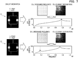
- FIG. 7 is an explanatory diagram for explaining an example of the estimation by using the circuit information.
- FIG. 7 illustrates an example of estimation of the EMI intensity by the information processing device 1 based on the circuit information of the electronic circuit to be analyzed.
- a solid line graph indicates a correct answer of the EMI intensity (EMI spectrum) at each frequency.
- a dotted line indicates the resonance frequency.
- a black dot indicates the correct answer of the EMI intensity at the resonance frequency, and a white dot indicates an estimated value of the EMI intensity by the information processing device 1.
- a case C1 and a case C2 have the same circuit configuration, but values of the circuit elements thereof are different from each other.
- C 100 pF and L: 10 nH
- C 100 pF and L: 100 pH
- the case C2 is a case where the value of L is smaller and the reflection is smaller.
- the resonance frequency and the current distribution generated using the various values of the LCR element at the resonance frequency are identified as the feature quantities of the electronic circuit to be analyzed. Therefore, for example, as in the case C2, even in a case where the value of L is sufficiently small and thus the reflection is small, the near field may be accurately approximated. Therefore, as the same as in the case C1, also in the case C2, the EMI intensity may be accurately estimated by estimating the EMI intensity by using the machine learning model based on the identified feature quantity.
- FIG. 8 is an explanatory diagram for explaining verification of the estimation result.
- FIG. 8 illustrates a verification result by using a holdout method for the estimation of the EMI intensity by the information processing device 1 using the machine learning model by 5000 epoch learning.
- an estimation result R of the information processing device 1 is close to a correct answer graph G and may be estimated with high accuracy.
- the input data creation unit 32 identifies the frequency, at which the maximum value of the current distribution of the electronic circuit to be analyzed is the highest, as the resonance frequency. Therefore, in the information processing device 1, the electromagnetic wave radiation situation (EMI intensity) may be estimated at the resonance frequency at which the maximum value of the current distribution is the highest in the electronic circuit to be analyzed. In circuit design, there is an interest in reducing the peak of the EMI spectrum. Therefore, it is sufficient in a case where the peak EMI intensity (the maximum value of the current distribution is the highest) may be predicted.
- the input data creation unit 32 identifies the resonance frequency and the current distribution for the electronic circuit to be analyzed by using the circuit simulator.
- the resonance frequency and the current distribution may be identified in the electronic circuit to be analyzed by the circuit simulator such as SPICE.
- the estimation unit 34 inputs, to the machine learning model, the value of the identified resonance frequency and the current distribution obtained through division performed on the identified current distribution of the electronic circuit to be analyzed for each configuration of the circuit element included in the electronic circuit as the input data. Next, the estimation unit 34 estimates the electromagnetic wave radiation situation of the electronic circuit to be analyzed by adding the output from the machine learning model according to the input of the current distributions obtained through division for each configuration of the circuit element. Accordingly, even in the case where the electronic circuit to be analyzed has the complex circuit configuration, the information processing device 1 may estimate the electromagnetic wave radiation situation by using the machine learning model in which machine learning is performed with the training data having the simple circuit configuration.
- each of the components of each of the devices illustrated in the drawing is not demanded to be physically configured as illustrated in the drawing.
- specific forms of the separation and integration of each of the devices are not limited to the illustrated drawing. All or some of the devices may be functionally or physically separated and integrated in an arbitrary unit according to various loads, usage situations, and the like.
- the information processing device 1 may include one of a configuration (the input unit 31, the input data creation unit 32, and the learning unit 33) that executes the learning phase and a configuration (the input unit 31, the input data creation unit 32, and the estimation unit 34) that executes the estimation phase. For example, learning of the estimation model and estimation using the learned estimation model may be performed by different information processing devices.
- All or some of the various processing functions performed in the information processing device 1 may be executed over the CPU (or a microcomputer such as a microprocessor unit (MPU) or a micro controller unit (MCU)) or a graphics processing unit (GPU). Further, it is apparent that all or some of the various processing functions may be executed over programs, which are analyzed and executed by the CPU (or the microcomputer such as the MPU or the MCU) or the GPU, or over hardware by using a wired logic. The various processing functions performed in the information processing device 1 may be executed in such a way that a plurality of computers cooperate via cloud computing.
- MPU microprocessor unit
- MCU micro controller unit
- GPU graphics processing unit
- FIG. 9 is a block diagram illustrating an example of a configuration of the computer.
- a computer 200 includes a CPU 201 that executes various arithmetic processing, a GPU 201a that is specialized for predetermined arithmetic processing such as the image processing or the machine learning processing, an input device 202 that receives data input, a monitor 203, and a speaker 204.
- the computer 200 also includes a medium reading device 205 that reads a program or the like from a storage medium, an interface device 206 that couples various devices, and a communication device 207 that performs communication coupling with an external device in wired or wireless manner.
- the computer 200 also includes a RAM 208 that temporarily stores various information, and a hard disk device 209. Each of the units (201 to 209) in the computer 200 is coupled to a bus 210.
- the hard disk device 209 stores programs 211 for executing various processing in the input unit 31, the input data creation unit 32, the learning unit 33, the estimation unit 34, and the like which are described in the embodiment.
- the hard disk device 209 stores various data 212 such as the training data set 21 and the estimation model information 22 to which the programs 211 refers.
- the input device 202 receives input of operation information from, for example, an operator.
- the monitor 203 displays various screens operated by, for example, the operator.
- a printer or the like is coupled to the interface device 206.
- the communication device 207 is coupled to a communication network such as a local area network (LAN), and exchanges various information with the external device via the communication network.
- LAN local area network
- the CPU 201 or the GPU 201a reads the programs 211 stored in the hard disk device 209 and deploys and executes the programs 211 in the RAM 208, thereby performing various processing related to the input unit 31, the input data creation unit 32, the learning unit 33, the estimation unit 34, and the like.
- the programs 211 may not be stored in the hard disk device 209.
- the programs 211 stored in the storage medium, which is readable by the computer 200, may be read and executed.
- the storage medium which is readable by the computer 200 corresponds to, for example, a portable recording medium, such as a compact disc read-only memory (CD-ROM), a Digital Versatile Disc (DVD), or a Universal Serial Bus (USB) memory, a semiconductor memory such as a flash memory, a hard disk drive, or the like.
- the programs 211 may be stored in a device coupled to a public network, the Internet, a LAN, or the like, and the computer 200 may read and execute the programs 211 from the device.
Landscapes
- Engineering & Computer Science (AREA)
- Theoretical Computer Science (AREA)
- Computer Hardware Design (AREA)
- Physics & Mathematics (AREA)
- General Engineering & Computer Science (AREA)
- Evolutionary Computation (AREA)
- General Physics & Mathematics (AREA)
- Geometry (AREA)
- Software Systems (AREA)
- Computing Systems (AREA)
- Mathematical Physics (AREA)
- Data Mining & Analysis (AREA)
- Artificial Intelligence (AREA)
- Computational Linguistics (AREA)
- Microelectronics & Electronic Packaging (AREA)
- Medical Informatics (AREA)
- Computer Vision & Pattern Recognition (AREA)
- Health & Medical Sciences (AREA)
- Life Sciences & Earth Sciences (AREA)
- Biomedical Technology (AREA)
- Biophysics (AREA)
- General Health & Medical Sciences (AREA)
- Molecular Biology (AREA)
- Shielding Devices Or Components To Electric Or Magnetic Fields (AREA)
- Management, Administration, Business Operations System, And Electronic Commerce (AREA)
Abstract
Description
- The embodiment discussed herein is related to a machine learning estimation program, a machine learning estimation method, and an information processing device.
- In recent years, estimation of an electromagnetic wave radiation situation (EMI), which is radiated from a circuit, is performed using a machine learning technology such as deep learning (DL). The electromagnetic wave radiation situation indicates a situation of a far electromagnetic field, and is also referred to as a far field. For example, in an estimation method by using the DL, the electromagnetic wave radiation situation is estimated based on an electronic circuit to be analyzed, by using a learning model generated from learning data in which a learning electronic circuit and a simulation result of electromagnetic wave analysis for the electronic circuit are paired.
- Related techniques are disclosed in, for example, Japanese National Publication of International Patent Application No.
2009-534854 - However, in the related art described above, a situation of a near electromagnetic field (near field) generated by various values of elements including an inductor (L), a capacitor (C), and a resistor (R) may not be accurately approximated, and thus there is a problem in that it is difficult to accurately estimate a far field in some cases.
- For example, in a case where the values of L, C, and R are sufficiently large, reflection occurs due to the L, C, and R elements (hereinafter, referred to as an LCR element). Therefore, in a case where the circuit is regarded as two lines obtained by being cut at the LCR element, the near field may be approximated based on a total length of the respective lines. However, a case where the values of L, C, and R are small and the reflection is small is exactly the same as a case where the LCR element is not present, so that it is difficult to accurately approximate an approximation field.
- In one aspect, an object is to provide an estimation technique which may support accurate estimation of an electromagnetic wave radiation situation.
- According to an aspect of the embodiment, a machine learning estimation program causes a computer to execute a process, the process comprising identifying, for an electronic circuit to be analyzed, a resonance frequency of a current and a spatial distribution of the current that flows through the electronic circuit to be analyzed at the resonance frequency, generating a machine learning model using a training data set in which arrangements of circuit elements in respective electronic circuits differ from each other, the training data set being a set of training data in each of which a specific value of a resonance frequency for a specific electronic circuit and information of a spatial distribution of a current that flows through the specific electronic circuit at the resonance frequency of the specific value are used as input data and an electromagnetic wave radiation situation of the specific electronic circuit is set as a label, inputting, as input data, a frequency value of the identified resonance frequency and information of the identified spatial distribution to the generated machine learning model, and estimating an electromagnetic wave radiation situation of the electronic circuit to be analyzed, based on an output from the machine learning model according to the inputting.
- According to an aspect of the embodiment, accurate estimation of an electromagnetic wave radiation situation may be supported.
-
-
FIG. 1 is an explanatory diagram for explaining an overview of a learning phase and an estimation phase according to an embodiment; -
FIG. 2 is a block diagram illustrating an example of a functional configuration of an information processing device according to the embodiment; -
FIG. 3 is a flowchart illustrating an example of an operation of the information processing device according to the embodiment; -
FIG. 4 is a flowchart illustrating an example of input data generation processing; -
FIG. 5 is an explanatory diagram for explaining an overview of the input data generation processing; -
FIG. 6 is an explanatory diagram for explaining a case where division is performed on current distribution; -
FIG. 7 is an explanatory diagram for explaining an example of estimation by using circuit information; -
FIG. 8 is an explanatory diagram for explaining verification of an estimation result; and -
FIG. 9 is a block diagram illustrating an example of a configuration of a computer. - Hereinafter, an estimation technique according to an embodiment will be described with reference to the accompanying drawings. In the embodiment, the same reference numeral is attached to a component having the same function, and the description thereof will not be repeated. The estimation program, the model generation program, the estimation method, the model generation method, the estimation device, and the model generation device, which will be described in the embodiment below, are merely examples and do not limit the embodiment. Further, the embodiment below may be appropriately combined in a scope which is not inconsistent.
- First, an overview of the present embodiment, in which an electromagnetic wave radiation situation (EMI intensity) in an electronic circuit to be analyzed, will be described. One point of interest in the present embodiment is that a far field of electromagnetic wave radiation in the electronic circuit to be analyzed is determined by an approximation field, and a near field is determined by a current flowing through the circuit.
- For example, in the electronic circuit, wiring serves as an antenna to generate an electromagnetic field, and a part of energy of the electromagnetic field is radiated as the EMI. An intensity of the electromagnetic field is determined by the amount of current flowing through the wiring. Therefore, the near field may be approximated by using a spatial distribution (hereinafter, also referred to as a current distribution) of the current flowing through the electronic circuit to be analyzed.
- The current flowing through the electronic circuit differs for each frequency. For example, the current distribution has a distribution over the frequency. However, in a case where machine learning is performed on a relationship between the current distributions at all frequencies and the EMI intensity, there is a problem in that the number of pieces of data to be learned becomes unrealistic.
- In circuit design, there is an interest in reducing a peak of an EMI spectrum. The peak of the EMI spectrum is obtained as a frequency at which a maximum value of the current distribution is the highest. A peak frequency is referred to as a resonance frequency.
- Therefore, another point of interest in the present embodiment is to perform machine learning by focusing on the current distribution at the resonance frequency. For example, in a learning phase, a value of the resonance frequency of the electronic circuit and the current distribution of the electronic circuit at the resonance frequency are set as feature quantities, and the machine learning is performed on a relationship of the EMI intensity with respect to the feature quantities, so that an estimation model is generated. In an estimation phase, the value of the resonance frequency and the current distribution at the resonance frequency are identified for the electronic circuit to be analyzed, and the value of the identified resonance frequency and the current distribution are input to the estimation model, so that the estimated value of the EMI intensity is obtained based on the output from the estimation model.
-
FIG. 1 is an explanatory diagram for explaining an overview of the learning phase and the estimation phase according to the embodiment. As illustrated inFIG. 1 , in the learning phase, circuit information in an electronic circuit of each case is acquired from a training data set including cases to be learned in which arrangements of circuit elements in the electronic circuit differ from each other (S1). The circuit information includes, for example, information on a circuit network (for example, a network list) of the circuit element (LCR element) included in the electronic circuit, a physical property value (a resistance value, inductance, or electrostatic capacitance) of each circuit element, and the like. - Next, in the learning phase, based on the circuit information, the current distribution at each frequency in the electronic circuit is calculated by a circuit simulator such as a simulation program with integrated circuit emphasis (SPICE) (S2).
- In order to approximate the near field of the electronic circuit, an output in S2 is an image on which coloring processing is performed such that the color becomes lighter as being far away from lines based on intensity information of the current distribution. For example, the output in S2 is information (image information) indicating an intensity of the current distribution that approximates the near field of the electronic circuit. The current distribution over a two-dimensional circuit has a smaller amount of calculation, compared to a three-dimensional electromagnetic field, so that the current distribution may be calculated in a much short time.
- Next, in the learning phase, a resonance frequency (f1, f2) at which the maximum value of the calculated current distribution is the highest is identified, and the current distribution for each resonance frequency (f1, f2) is obtained (S3).
- Next, in the learning phase, information on the identified frequency (value of the resonance frequency) is input as input data of a channel 1 (Ch. 1), and information on the current distribution at the frequency (image indicating the current distribution) is input as input data of a channel 2 (Ch. 2) to the estimation model such as deep learning (S4). For example, in S4, the resonance frequency (f1) is input to the estimation model as Ch. 1, and the current distribution at the resonance frequency (f1) is input to the estimation model as Ch. 2. Alternatively, the resonance frequency (f2) is input to the estimation model as Ch. 1, and the current distribution at the resonance frequency (f2) is input to the estimation model as Ch. 2.
- Next, in the learning phase, parameters of the estimation model are learned (learned by using an error back propagation method) so that the output from the estimation model for the inputs of Ch. 1 and Ch. 2 approaches a correct answer label (EMI intensity) included in the training data set (S5).
- In the estimation phase, instead of the circuit information of the electronic circuit to be learned, the circuit information of the electronic circuit to be analyzed is acquired and the processes in S1 to S4 are performed.
- For example, in the estimation phase, the circuit information in the electronic circuit to be analyzed is acquired by an input from a user, or the like (S1). Next, in the estimation phase, based on the circuit information, the current distribution at each frequency in the electronic circuit is calculated by the circuit simulator such as SPICE (S2). Next, in the estimation phase, the resonance frequency (f1, f2) at which the maximum value of the calculated current distribution is the highest is identified, and the current distribution for each resonance frequency (f1, f2) is obtained (S3).
- Next, in the estimation phase, the information on the identified frequency (the value of the resonance frequency) is input as the input data of the channel 1 (Ch. 1), and the information on the current distribution at the frequency (the image indicating the current distribution) is input as the input data of the channel 2 (Ch. 2) to the estimation model such as the deep learning
- (S4). Thus, in the estimation phase, the estimated value of the EMI intensity is obtained based on the output from the estimation model (S5).
-
FIG. 2 is a block diagram illustrating an example of a functional configuration of the information processing device according to the embodiment. As illustrated inFIG. 2 , theinformation processing device 1 is a computer that includes acommunication unit 10, astorage unit 20, and acontrol unit 30, and that executes the learning phase and the estimation phase which are described above. For example, a personal computer (PC) or the like may be applied to theinformation processing device 1. For example, theinformation processing device 1 is an example of an estimation device or a model generation device. - The
communication unit 10 communicates with input devices, such as a keyboard and a mouse, and other information processing devices via a LAN, a communication cable, or the like under the control of thecontrol unit 30. Theinformation processing device 1 receives, for example, an input of atraining data set 21 for training the estimation model and an input of circuit information of the electronic circuit to be analyzed via thecommunication unit 10. - The
storage unit 20 is, for example, a semiconductor memory element, such as a random-access memory (RAM) or a flash memory, or a storage device such as a hard disk or an optical disk. Thestorage unit 20 includes thetraining data set 21,estimation model information 22, and estimation resultinformation 23. - The
training data set 21 is a data set of training data including cases to be learned in which the arrangements of the circuit elements in the electronic circuit differ from each other. For example, the training data of thetraining data set 21 includes the circuit information and the correct answer label (EMI intensity) in each case. - The
estimation model information 22 is a parameter or the like for constructing a machine learning model (estimation model) generated by the machine learning. - The estimation result
information 23 is an estimation result obtained by using the estimation model of theestimation model information 22 for the circuit information of the electronic circuit to be analyzed. For example, the estimation resultinformation 23 is a value of the EMI intensity for each resonance frequency in the electronic circuit to be analyzed. - The
control unit 30 corresponds to the electronic circuit such as a central processing unit (CPU). Thecontrol unit 30 includes an internal memory for storing programs defining various processing procedures and control data, and executes various processing by using the programs and the control data. - For example, the
control unit 30 includes aninput unit 31, an inputdata creation unit 32, alearning unit 33, and anestimation unit 34. The inputdata creation unit 32 is an example of an identification unit or an acquisition unit. Thelearning unit 33 is an example of a model generation unit. - The
input unit 31 is a processing unit that receives input of various information such as thetraining data set 21 and the circuit information of the electronic circuit to be analyzed. For example, theinput unit 31 stores thetraining data set 21 input via thecommunication unit 10 in thestorage unit 20. Theinput unit 31 outputs the circuit information of the electronic circuit to be analyzed input via thecommunication unit 10 to the inputdata creation unit 32. - The input
data creation unit 32 is a processing unit that generates the input data to be input to the estimation model. For example, the inputdata creation unit 32 calculates the current distribution at each frequency in the electronic circuit by the circuit simulator such as SPICE based on the circuit information. Next, the inputdata creation unit 32 identifies the resonance frequency at which the maximum value of the calculated current distribution is the highest, and identifies the current distribution for each resonance frequency. Next, the inputdata creation unit 32 generates the input data in which the identified resonance frequency is set to Ch. 1 and the current distribution at the resonance frequency is set to Ch. 2. - The
learning unit 33 is a processing unit that learns the parameters of the estimation model by the machine learning (learning by using the error back propagation method). For example, thelearning unit 33 learns the parameters of the estimation model such that the output from the estimation model for the input data (Ch. 1: the value of the resonance frequency, Ch. 2: the current distribution at the resonance frequency) generated by the inputdata creation unit 32 for the case to be learned approaches the correct answer label (EMI intensity) of the case. Next, thelearning unit 33 stores the parameters of the estimation model obtained by the learning in thestorage unit 20 as theestimation model information 22. - The
estimation unit 34 is a processing unit that estimates the electromagnetic wave radiation situation in the electronic circuit to be analyzed by using the estimation model generated by the machine learning of thelearning unit 33. For example, theestimation unit 34 inputs the input data (Ch. 1: the value of the resonance frequency, Ch. 2: the current distribution at the resonance frequency) generated by the inputdata creation unit 32 for the electronic circuit to be analyzed to the estimation model based on theestimation model information 22. Next, theestimation unit 34 obtains the estimated value (estimation result) of the EMI intensity based on the output from the estimation model according to the input. Next, theestimation unit 34 stores the obtained estimation result in thestorage unit 20 as the estimation resultinformation 23, together with, for example, the electronic circuit to be analyzed. -
FIG. 3 is a flowchart illustrating an example of an operation of the information processing device according to the embodiment. As illustrated inFIG. 3 , in a case where the processing is started, theinput unit 31 receives input of the circuit information to be learned or estimated via thecommunication unit 10 or the like (S10). - Next, based on the circuit information to be learned or estimated, the input
data creation unit 32 creates the input data (Ch. 1: the value of the resonance frequency, Ch. 2: the current distribution at the resonance frequency) to be input to the estimation model (S11). -
FIG. 4 is a flowchart illustrating an example of input data generation processing.FIG. 5 is an explanatory diagram for explaining an overview of the input data generation processing. - As illustrated in
FIG. 4 , in a case where the input data generation processing is started, the inputdata creation unit 32 receives the input of the circuit information which is a processing target of the learning or the estimation (S20), and calculates the current distribution over the circuit at each frequency by using the circuit simulator such as SPICE (S21). - For example, in the example of
FIG. 5 , in S20, circuit information D1 of the electronic circuit, in which the circuit elements of R (100 Ω) and C (100 pF) are coupled in parallel, is input. The inputdata creation unit 32 calculates the current distribution at each frequency by the circuit simulator (for example, SPICE) based on the circuit information D1. - Next, the input
data creation unit 32 executes loop processing (S22 to S27) in the current distribution at each frequency. - For example, in a case where the loop processing is started, the input
data creation unit 32 determines whether or not the maximum value of the current distribution is the highest (resonance frequency) (S23). In a case where the frequency is not the resonance frequency (S23: No), the inputdata creation unit 32 returns the process to S22, and continues the loop processing related to the current distribution at a subsequent frequency. - In a case where the frequency is the resonance frequency (S23: Yes), the input
data creation unit 32 generates a two-dimensional matrix, in which a wiring pattern of the electronic circuit is colored with the current distribution in order to approximate the near field, for example, an image indicating the current distribution (S24). - Next, the input
data creation unit 32 generates a matrix filled with the elements using the resonance frequency (S25). For example, the inputdata creation unit 32 creates a matrix having the same size as the matrix generated in S24, and assigns the value of the resonance frequency to each of the elements of the matrix. - In a case where a plurality of channels (Ch. 1 and Ch. 2) are input to the estimation model, types of the matrices of the respective channels are demanded to be the same. Therefore, in S25, in a case where scalar (the value of the resonance frequency) is converted into the matrix, handling as a standard neural network model (estimation model) is possible.
- As illustrated in
FIG. 5 , in S23 to S25, the inputdata creation unit 32 obtains the matrix filled with the value of the resonance frequency and an image (matrix) of the current distribution at the resonance frequency. - Next, the input
data creation unit 32 creates input data in which the two matrices in S24 and S25 are stored in Ch. 1 and Ch. 2 (S26). For example, as illustrated inFIG. 5 , the inputdata creation unit 32 creates input data D2 of Ch. 1 relating to information (matrix) on the resonance frequency and input data D3 of Ch. 2 relating to information (matrix) on the current distribution at the resonance frequency. Next, the inputdata creation unit 32 returns the process to S22 until processing for the current distribution at all the frequencies is completed, and continues the loop processing. - After the loop processing, the input
data creation unit 32 outputs the input data D2 and D3 to be input to the estimation model to thelearning unit 33 or the estimation unit 34 (S28). - Returning to
FIG. 3 , theinformation processing device 1 executes estimation using learning of the estimation model and learned estimation model by performing the loop processing (S12 to S14) for the input data D2 and D3 created by the inputdata creation unit 32 for each resonance frequency. - For example, in a case of the learning (learning phase) of the estimation model based on the circuit information of the electronic circuit to be learned, the
learning unit 33 learns the parameters such that the output from the estimation model for the input data D2 (Ch. 1: the value of the resonance frequency) and the input data D3 (Ch. 2: the current distribution at the resonance frequency) approaches the correct answer label. - In a case of the estimation (estimation phase) based on the circuit information of the electronic circuit to be analyzed, the
estimation unit 34 obtains an estimated value (estimation result) of the EMI intensity by using the output from the estimation model for the input data D2 (Ch. 1: the value of the resonance frequency) and the input data D3 (Ch. 2: the current distribution at the resonance frequency). - Next, the
information processing device 1 outputs a result of the estimation or the learning (S15). For example, in a case of the learning phase, thelearning unit 33 stores the parameters of the estimation model, which are obtained by the learning, in thestorage unit 20 as theestimation model information 22. In a case of the estimation phase, theestimation unit 34 stores the estimation resultinformation 23, which includes the obtained estimation result, in thestorage unit 20. - In the learning phase, the
information processing device 1 learns the estimation model with thetraining data set 21 having a simple circuit configuration using LCR elements. In the estimation phase, theinformation processing device 1 inputs, to the estimation model, a result of division performed on the current distributions for each configuration of the circuit element included in the electronic circuit to be analyzed. Next, theinformation processing device 1 may estimate the electromagnetic wave radiation situation of the electronic circuit to be analyzed by adding the output from the estimation model. -
FIG. 6 is an explanatory diagram for explaining a case where the division is performed on the current distribution. As illustrated inFIG. 6 , in a learning phase P1, theinformation processing device 1 learns the estimation model using learning cases P1a, P1b, Pic, P1d ... having a simple circuit configuration. - For example, the learning case P1a is a case of the current distribution and a correct answer label (EMI intensity at the resonance frequency) in a case where the circuit configuration does not include an element. Similarly, the learning case P1b is a case of a circuit configuration of C: 10 pF, the learning case Pic is a case of a circuit configuration of C: 100 pF, and the learning case P1d is a case of a circuit configuration of R: 100 Ω.
- In an estimation phase P2, the input
data creation unit 32 identifies a current distribution D4 at the resonance frequency (S11a). With respect to the identified current distribution D4, theestimation unit 34 performs division on the current distribution for each configuration of the circuit element included in the electronic circuit (S11b). For example, theestimation unit 34 performs division on the current distribution D4 at a point of a circuit branch in the circuit information, and obtains current distributions D4a and D4b. - Next, the
estimation unit 34 individually inputs the obtained current distributions D4a and D4b to the estimation model to obtain respective outputs thereof (estimated values of the EMI intensity) (S13a). Next, theestimation unit 34 adds the obtained outputs (S13b) to estimate the electromagnetic wave radiation situation of the electronic circuit to be analyzed. - Accordingly, even in a case where the electronic circuit to be analyzed has a complex circuit configuration, the
information processing device 1 may estimate the electromagnetic wave radiation situation by using the estimation model learned with thetraining data set 21 having the simple circuit configuration. - As described above, the
information processing device 1 includes the inputdata creation unit 32 and theestimation unit 34. The inputdata creation unit 32 identifies, for the electronic circuit to be analyzed, the resonance frequency of the current and the spatial distribution (current distribution) of the current flowing through the electronic circuit to be analyzed at the resonance frequency. Theestimation unit 34 inputs the value of the identified resonance frequency and the current distribution of the identified electronic circuit to be analyzed to the estimation model (machine learning model) of theestimation model information 22 as the input data. Next, theestimation unit 34 estimates the electromagnetic wave radiation situation of the electronic circuit to be analyzed based on the output from the machine learning model. Theestimation model information 22 related to the machine learning model is generated by using the training data set in which the arrangements of the circuit elements in the electronic circuit differ from each other, the training data set being a set of the training data in which the value of the resonance frequency for the electronic circuit and the current distribution of the electronic circuit at the resonance frequency are used as the input data and the electromagnetic wave radiation situation of the electronic circuit is set as a label. - Therefore, in the
information processing device 1, the spatial distribution (current distribution) of the current generated using various values of the LCR element included in the electronic circuit to be analyzed may be identified, and the near field of the electronic circuit to be analyzed may be accurately approximated. Therefore, in theinformation processing device 1, the electromagnetic wave radiation situation (EMI) in the electronic circuit to be analyzed may be estimated with high accuracy by using the machine learning model in which machine learning is performed on the electromagnetic wave radiation situation of the electronic circuit using the resonance frequency of the current in the electronic circuit and the current distribution at the resonance frequency as the feature quantities. -
FIG. 7 is an explanatory diagram for explaining an example of the estimation by using the circuit information. For example,FIG. 7 illustrates an example of estimation of the EMI intensity by theinformation processing device 1 based on the circuit information of the electronic circuit to be analyzed. InFIG. 7 , a solid line graph indicates a correct answer of the EMI intensity (EMI spectrum) at each frequency. A dotted line indicates the resonance frequency. A black dot indicates the correct answer of the EMI intensity at the resonance frequency, and a white dot indicates an estimated value of the EMI intensity by theinformation processing device 1. - A case C1 and a case C2 have the same circuit configuration, but values of the circuit elements thereof are different from each other. For example, in the case C1, C: 100 pF and L: 10 nH, and, in the case C2, C: 100 pF and L: 100 pH. For example, the case C2 is a case where the value of L is smaller and the reflection is smaller.
- As illustrated in
FIG. 7 , in theinformation processing device 1, based on the circuit information in the electronic circuit to be analyzed, the resonance frequency and the current distribution generated using the various values of the LCR element at the resonance frequency are identified as the feature quantities of the electronic circuit to be analyzed. Therefore, for example, as in the case C2, even in a case where the value of L is sufficiently small and thus the reflection is small, the near field may be accurately approximated. Therefore, as the same as in the case C1, also in the case C2, the EMI intensity may be accurately estimated by estimating the EMI intensity by using the machine learning model based on the identified feature quantity. -
FIG. 8 is an explanatory diagram for explaining verification of the estimation result. For example,FIG. 8 illustrates a verification result by using a holdout method for the estimation of the EMI intensity by theinformation processing device 1 using the machine learning model by 5000 epoch learning. As illustrated inFIG. 8 , an estimation result R of theinformation processing device 1 is close to a correct answer graph G and may be estimated with high accuracy. - The input
data creation unit 32 identifies the frequency, at which the maximum value of the current distribution of the electronic circuit to be analyzed is the highest, as the resonance frequency. Therefore, in theinformation processing device 1, the electromagnetic wave radiation situation (EMI intensity) may be estimated at the resonance frequency at which the maximum value of the current distribution is the highest in the electronic circuit to be analyzed. In circuit design, there is an interest in reducing the peak of the EMI spectrum. Therefore, it is sufficient in a case where the peak EMI intensity (the maximum value of the current distribution is the highest) may be predicted. - The input
data creation unit 32 identifies the resonance frequency and the current distribution for the electronic circuit to be analyzed by using the circuit simulator. Thus, in theinformation processing device 1, for example, the resonance frequency and the current distribution may be identified in the electronic circuit to be analyzed by the circuit simulator such as SPICE. - The
estimation unit 34 inputs, to the machine learning model, the value of the identified resonance frequency and the current distribution obtained through division performed on the identified current distribution of the electronic circuit to be analyzed for each configuration of the circuit element included in the electronic circuit as the input data. Next, theestimation unit 34 estimates the electromagnetic wave radiation situation of the electronic circuit to be analyzed by adding the output from the machine learning model according to the input of the current distributions obtained through division for each configuration of the circuit element. Accordingly, even in the case where the electronic circuit to be analyzed has the complex circuit configuration, theinformation processing device 1 may estimate the electromagnetic wave radiation situation by using the machine learning model in which machine learning is performed with the training data having the simple circuit configuration. - Note that, each of the components of each of the devices illustrated in the drawing is not demanded to be physically configured as illustrated in the drawing. For example, specific forms of the separation and integration of each of the devices are not limited to the illustrated drawing. All or some of the devices may be functionally or physically separated and integrated in an arbitrary unit according to various loads, usage situations, and the like.
- The
information processing device 1 may include one of a configuration (theinput unit 31, the inputdata creation unit 32, and the learning unit 33) that executes the learning phase and a configuration (theinput unit 31, the inputdata creation unit 32, and the estimation unit 34) that executes the estimation phase. For example, learning of the estimation model and estimation using the learned estimation model may be performed by different information processing devices. - All or some of the various processing functions performed in the
information processing device 1 may be executed over the CPU (or a microcomputer such as a microprocessor unit (MPU) or a micro controller unit (MCU)) or a graphics processing unit (GPU). Further, it is apparent that all or some of the various processing functions may be executed over programs, which are analyzed and executed by the CPU (or the microcomputer such as the MPU or the MCU) or the GPU, or over hardware by using a wired logic. The various processing functions performed in theinformation processing device 1 may be executed in such a way that a plurality of computers cooperate via cloud computing. - The various processing described in the embodiment may be realized in such a way that the computer executes a program prepared in advance. Hereinafter, an example of the computer (hardware) that executes the program having the same function as in the above-described embodiment will be described below.
FIG. 9 is a block diagram illustrating an example of a configuration of the computer. - As illustrated in
FIG. 9 , acomputer 200 includes aCPU 201 that executes various arithmetic processing, aGPU 201a that is specialized for predetermined arithmetic processing such as the image processing or the machine learning processing, aninput device 202 that receives data input, amonitor 203, and aspeaker 204. Thecomputer 200 also includes amedium reading device 205 that reads a program or the like from a storage medium, aninterface device 206 that couples various devices, and acommunication device 207 that performs communication coupling with an external device in wired or wireless manner. Thecomputer 200 also includes aRAM 208 that temporarily stores various information, and ahard disk device 209. Each of the units (201 to 209) in thecomputer 200 is coupled to abus 210. - The
hard disk device 209 stores programs 211 for executing various processing in theinput unit 31, the inputdata creation unit 32, thelearning unit 33, theestimation unit 34, and the like which are described in the embodiment. Thehard disk device 209 storesvarious data 212 such as thetraining data set 21 and theestimation model information 22 to which the programs 211 refers. Theinput device 202 receives input of operation information from, for example, an operator. Themonitor 203 displays various screens operated by, for example, the operator. For example, a printer or the like is coupled to theinterface device 206. Thecommunication device 207 is coupled to a communication network such as a local area network (LAN), and exchanges various information with the external device via the communication network. - The
CPU 201 or theGPU 201a reads the programs 211 stored in thehard disk device 209 and deploys and executes the programs 211 in theRAM 208, thereby performing various processing related to theinput unit 31, the inputdata creation unit 32, thelearning unit 33, theestimation unit 34, and the like. The programs 211 may not be stored in thehard disk device 209. For example, the programs 211 stored in the storage medium, which is readable by thecomputer 200, may be read and executed. The storage medium which is readable by thecomputer 200 corresponds to, for example, a portable recording medium, such as a compact disc read-only memory (CD-ROM), a Digital Versatile Disc (DVD), or a Universal Serial Bus (USB) memory, a semiconductor memory such as a flash memory, a hard disk drive, or the like. The programs 211 may be stored in a device coupled to a public network, the Internet, a LAN, or the like, and thecomputer 200 may read and execute the programs 211 from the device.
Claims (14)
- A machine learning estimation program that causes a computer to execute a process, the process comprising:identifying, for an electronic circuit to be analyzed, a resonance frequency of a current and a spatial distribution of the current that flows through the electronic circuit to be analyzed at the resonance frequency;generating a machine learning model using a training data set in which arrangements of circuit elements in respective electronic circuits differ from each other, the training data set being a set of training data in each of which a specific value of a resonance frequency for a specific electronic circuit and information of a spatial distribution of a current that flows through the specific electronic circuit at the resonance frequency of the specific value are used as input data and an electromagnetic wave radiation situation of the specific electronic circuit is set as a label;inputting, as input data, a frequency value of the identified resonance frequency and information of the identified spatial distribution to the generated machine learning model; andestimating an electromagnetic wave radiation situation of the electronic circuit to be analyzed, based on an output from the machine learning model according to the inputting.
- The machine learning estimation program according to claim 1, wherein
the identifying includes identifying, as the resonance frequency, a frequency at which a maximum value of the spatial distribution of the current that flows through the electronic circuit to be analyzed is highest. - The machine learning estimation program according to claim 1 or 2, wherein
the identifying includes identifying the resonance frequency and the spatial distribution for the electronic circuit to be analyzed by using a circuit simulator. - The machine learning estimation program according to any one of claims 1 to 3, the process further comprising:dividing the identified spatial distribution into several spatial distributions in accordance with configurations of respective circuit elements included in the electronic circuit to be analyzed,whereinthe inputting includes inputting, as the input data, the value of the identified resonance frequency and each of the several spatial distributions to the machine learning model, andthe estimating includes estimating the electromagnetic wave radiation situation of the electronic circuit to be analyzed by adding the output from the machine learning model according to the input of each of the several spatial distributions.
- A machine learning estimation method for analyzing electronic circuits, the machine learning estimation method comprising:identifying by a computer, for an electronic circuit to be analyzed, a resonance frequency of a current and a spatial distribution of the current that flows through the electronic circuit to be analyzed at the resonance frequency;generating a machine learning model using a training data set in which arrangements of circuit elements in respective electronic circuits differ from each other, the training data set being a set of training data in each of which a specific value of a resonance frequency for a specific electronic circuit and information of a spatial distribution of a current that flows through the specific electronic circuit at the resonance frequency of the specific value are used as input data and an electromagnetic wave radiation situation of the specific electronic circuit is set as a label;inputting, as input data, a frequency value of the identified resonance frequency and information of the identified spatial distribution to the generated machine learning model; andestimating an electromagnetic wave radiation situation of the electronic circuit to be analyzed, based on an output from the machine learning model according to the inputting.
- The machine learning estimation method according to claim 5, wherein
the identifying includes identifying, as the resonance frequency, a frequency at which a maximum value of the spatial distribution of the current that flows through the electronic circuit to be analyzed is highest. - The machine learning estimation method according to claim 5 or 6, wherein
the identifying includes identifying the resonance frequency and the spatial distribution for the electronic circuit to be analyzed by using a circuit simulator. - The machine learning estimation method according to any one of claims 5 to 7, further comprising:dividing the identified spatial distribution into several spatial distributions in accordance with configurations of respective circuit elements included in the electronic circuit to be analyzed,whereinthe inputting includes inputting, as the input data, the value of the identified resonance frequency and each of the several spatial distributions to the machine learning model, andthe estimating includes estimating the electromagnetic wave radiation situation of the electronic circuit to be analyzed by adding the output from the machine learning model according to the input of each of the several spatial distributions.
- An information processing device, comprising:an identification unit configured to identify, for an electronic circuit to be analyzed, a resonance frequency of a current and a spatial distribution of the current that flows through the electronic circuit to be analyzed at the resonance frequency;a model generation unit configured to generate a machine learning model using a training data set in which arrangements of circuit elements in respective electronic circuits differ from each other, the training data set being a set of training data in each of which a specific value of a resonance frequency for a specific electronic circuit and information of a spatial distribution of a current that flows through the specific electronic circuit at the specific value of the resonance frequency are used as input data and an electromagnetic wave radiation situation of the specific electronic circuit is set as a label; andan estimation unit configured to:input, as input data, a frequency value of the identified resonance frequency and information of the identified spatial distribution to the generated machine learning model; andestimate an electromagnetic wave radiation situation of the electronic circuit to be analyzed, based on an output from the machine learning model according to the inputting.
- The information processing device according to claim 9, wherein
the identification unit is configured to:
identify, as the resonance frequency, a frequency at which a maximum value of the spatial distribution of the current that flows through the electronic circuit to be analyzed is highest. - The information processing device according to claim 9 or 10, wherein
the identification unit is configured to:
identify the resonance frequency and the spatial distribution for the electronic circuit to be analyzed by using a circuit simulator. - The information processing device according to any one of claims 9 to 11, wherein
the estimation unit is further configured to:divide the identified spatial distribution into several spatial distributions in accordance with configurations of respective circuit elements included in the electronic circuit to be analyzed;input, as the input data, the value of the identified resonance frequency and each of the several spatial distributions to the machine learning model; andestimate the electromagnetic wave radiation situation of the electronic circuit to be analyzed by adding the output from the machine learning model according to the input of each of the several spatial distributions. - The machine learning estimation program according to any one of claims 1 to 4, wherein
a far field of the estimated electromagnetic wave radiation in the electronic circuit to be analyzed is determined by an approximation field, and a near field of the estimated electromagnetic wave radiation is determined by the current flowing through the electronic circuit. - The machine learning estimation program according to any one of claims 1 to 4 and 13, further comprising:
creating a two-dimensional matrix in which a wiring pattern of the electronic circuit is colored based on the spatial distribution of the current in order to represent the electromagnetic wave radiation situation.
Applications Claiming Priority (1)
| Application Number | Priority Date | Filing Date | Title |
|---|---|---|---|
| JP2020084147A JP7409220B2 (en) | 2020-05-12 | 2020-05-12 | Estimation program, model generation program, estimation method, model generation method, estimation device, and model generation device |
Publications (2)
| Publication Number | Publication Date |
|---|---|
| EP3910523A1 true EP3910523A1 (en) | 2021-11-17 |
| EP3910523B1 EP3910523B1 (en) | 2025-07-16 |
Family
ID=75143520
Family Applications (1)
| Application Number | Title | Priority Date | Filing Date |
|---|---|---|---|
| EP21163962.0A Active EP3910523B1 (en) | 2020-05-12 | 2021-03-22 | Machine learning program, method and device for estimating the electromagnetic wave radiation situation of an electronic circuit |
Country Status (3)
| Country | Link |
|---|---|
| US (1) | US20210357811A1 (en) |
| EP (1) | EP3910523B1 (en) |
| JP (1) | JP7409220B2 (en) |
Families Citing this family (2)
| Publication number | Priority date | Publication date | Assignee | Title |
|---|---|---|---|---|
| KR20220148913A (en) * | 2020-03-14 | 2022-11-07 | 시놉시스, 인크. | Machine Learning Based Metric Prediction in Early Stage Circuit Design |
| WO2025134410A1 (en) * | 2023-12-19 | 2025-06-26 | 株式会社デンソー | Analysis device, analysis program, method, semiconductor device, and semiconductor wafer |
Citations (1)
| Publication number | Priority date | Publication date | Assignee | Title |
|---|---|---|---|---|
| JP2009534854A (en) | 2006-04-21 | 2009-09-24 | アプライド マテリアルズ インコーポレイテッド | Neural network method and apparatus for monitoring substrate processing |
Family Cites Families (4)
| Publication number | Priority date | Publication date | Assignee | Title |
|---|---|---|---|---|
| JP3348709B2 (en) | 1999-11-24 | 2002-11-20 | 日本電気株式会社 | Printed circuit board design support apparatus and control program recording medium |
| JP5825197B2 (en) | 2012-05-18 | 2015-12-02 | 株式会社デンソー | Noise analysis apparatus, noise analysis method, and noise analysis program |
| WO2018140983A1 (en) | 2017-01-30 | 2018-08-02 | NeuSpera Medical Inc. | Midfield transmitter and injectable midfield receiver |
| WO2020095362A1 (en) | 2018-11-06 | 2020-05-14 | 三菱電機株式会社 | Design assistance device, design assistance method, and machine learning device |
-
2020
- 2020-05-12 JP JP2020084147A patent/JP7409220B2/en active Active
-
2021
- 2021-03-22 EP EP21163962.0A patent/EP3910523B1/en active Active
- 2021-03-29 US US17/216,262 patent/US20210357811A1/en active Pending
Patent Citations (1)
| Publication number | Priority date | Publication date | Assignee | Title |
|---|---|---|---|---|
| JP2009534854A (en) | 2006-04-21 | 2009-09-24 | アプライド マテリアルズ インコーポレイテッド | Neural network method and apparatus for monitoring substrate processing |
Non-Patent Citations (3)
| Title |
|---|
| JIN HANG ET AL: "EMI Radiation Prediction and Structure Optimization of Packages by Deep Learning", IEEE ACCESS, vol. 7, 10 July 2019 (2019-07-10), pages 93772 - 93780, XP011736497, DOI: 10.1109/ACCESS.2019.2927160 * |
| JIN HANG ET AL: "Machine learning for complex EMI prediction, optimization and localization", 2017 IEEE ELECTRICAL DESIGN OF ADVANCED PACKAGING AND SYSTEMS SYMPOSIUM (EDAPS), IEEE, 14 December 2017 (2017-12-14), pages 1 - 3, XP033308279, DOI: 10.1109/EDAPS.2017.8276967 * |
| YAO S ET AL: "An Equivalent Radiation Source Based on Artificial Neural Network for EMI Prediction", 2018 INTERNATIONAL SYMPOSIUM ON ELECTROMAGNETIC COMPATIBILITY (EMC EUROPE), IEEE, 27 August 2018 (2018-08-27), pages 556 - 560, XP033416235, DOI: 10.1109/EMCEUROPE.2018.8485100 * |
Also Published As
| Publication number | Publication date |
|---|---|
| JP7409220B2 (en) | 2024-01-09 |
| EP3910523B1 (en) | 2025-07-16 |
| US20210357811A1 (en) | 2021-11-18 |
| JP2021179749A (en) | 2021-11-18 |
Similar Documents
| Publication | Publication Date | Title |
|---|---|---|
| US10025696B2 (en) | System and method for equivalence class analysis-based automated requirements-based test case generation | |
| US11675951B2 (en) | Methods and systems for congestion prediction in logic synthesis using graph neural networks | |
| CN107679466B (en) | Information output method and device | |
| US20190042940A1 (en) | Information processing apparatus and component estimation method | |
| CN111831114B (en) | Driving voltage generation method and device, storage medium and electronic equipment | |
| JP6599057B1 (en) | Design support device, design support method, and machine learning device | |
| EP3910523B1 (en) | Machine learning program, method and device for estimating the electromagnetic wave radiation situation of an electronic circuit | |
| CN113627107A (en) | Method, apparatus, electronic device and medium for determining supply voltage data | |
| US12393750B2 (en) | Computer-readable recording medium storing machine learning program, information processing apparatus, and machine learning method | |
| US7110929B1 (en) | System and method of providing additional circuit analysis using simulation templates | |
| JP7658152B2 (en) | EMI calculation program, EMI calculation method, and EMI calculation device | |
| CN111385601B (en) | Video auditing method, system and equipment | |
| KR100999016B1 (en) | A method of estimating jitter based on simultaneous operation signal noise for a semiconductor device, a method of calculating the amount of simultaneous operation signal noise to jitter amount used for the estimation, a recording medium recording a program for realizing these, and a semiconductor device and How to design a printed circuit board on which it is mounted | |
| KR20170126312A (en) | Apparatus and Method for designing automation using FEM | |
| US9135376B2 (en) | Input space reduction for verification test set generation | |
| US20180101294A1 (en) | Information generating system, information generating device, information generating method, and information generating program | |
| JP2020030702A (en) | Learning device, learning method and learning program | |
| CN110135583B (en) | Method and device for generating label information and electronic equipment | |
| US20230237381A1 (en) | Non-transitory computer-readable recording medium storing training data generation program, training data generation method, and training data generation device | |
| CN112489030A (en) | Neural network training method for circuit board glue quality detection | |
| CN114186043B (en) | Pre-training method, device, equipment and storage medium | |
| KR102694598B1 (en) | System and method of improving predictions of images by adapting features of test images | |
| CN116205154B (en) | Aerodynamic coefficient generation method and device, terminal equipment and storage medium | |
| US12039238B1 (en) | Blackbox reduced order models of thermal systems | |
| US20250022548A1 (en) | Computer readable storage medium storing a machine learning program, machine learning method, and information processing apparatus |
Legal Events
| Date | Code | Title | Description |
|---|---|---|---|
| PUAI | Public reference made under article 153(3) epc to a published international application that has entered the european phase |
Free format text: ORIGINAL CODE: 0009012 |
|
| STAA | Information on the status of an ep patent application or granted ep patent |
Free format text: STATUS: THE APPLICATION HAS BEEN PUBLISHED |
|
| STAA | Information on the status of an ep patent application or granted ep patent |
Free format text: STATUS: REQUEST FOR EXAMINATION WAS MADE |
|
| AK | Designated contracting states |
Kind code of ref document: A1 Designated state(s): AL AT BE BG CH CY CZ DE DK EE ES FI FR GB GR HR HU IE IS IT LI LT LU LV MC MK MT NL NO PL PT RO RS SE SI SK SM TR |
|
| B565 | Issuance of search results under rule 164(2) epc |
Effective date: 20210819 |
|
| 17P | Request for examination filed |
Effective date: 20211021 |
|
| RBV | Designated contracting states (corrected) |
Designated state(s): AL AT BE BG CH CY CZ DE DK EE ES FI FR GB GR HR HU IE IS IT LI LT LU LV MC MK MT NL NO PL PT RO RS SE SI SK SM TR |
|
| STAA | Information on the status of an ep patent application or granted ep patent |
Free format text: STATUS: EXAMINATION IS IN PROGRESS |
|
| 17Q | First examination report despatched |
Effective date: 20230712 |
|
| REG | Reference to a national code |
Ref country code: DE Ref legal event code: R079 Free format text: PREVIOUS MAIN CLASS: G06F0030390000 Ipc: G06N0003084000 Ref country code: DE Ref legal event code: R079 Ref document number: 602021034057 Country of ref document: DE Free format text: PREVIOUS MAIN CLASS: G06F0030390000 Ipc: G06N0003084000 |
|
| GRAP | Despatch of communication of intention to grant a patent |
Free format text: ORIGINAL CODE: EPIDOSNIGR1 |
|
| STAA | Information on the status of an ep patent application or granted ep patent |
Free format text: STATUS: GRANT OF PATENT IS INTENDED |
|
| RIC1 | Information provided on ipc code assigned before grant |
Ipc: G06N 3/084 20230101AFI20250124BHEP |
|
| INTG | Intention to grant announced |
Effective date: 20250218 |
|
| GRAS | Grant fee paid |
Free format text: ORIGINAL CODE: EPIDOSNIGR3 |
|
| GRAA | (expected) grant |
Free format text: ORIGINAL CODE: 0009210 |
|
| STAA | Information on the status of an ep patent application or granted ep patent |
Free format text: STATUS: THE PATENT HAS BEEN GRANTED |
|
| AK | Designated contracting states |
Kind code of ref document: B1 Designated state(s): AL AT BE BG CH CY CZ DE DK EE ES FI FR GB GR HR HU IE IS IT LI LT LU LV MC MK MT NL NO PL PT RO RS SE SI SK SM TR |
|
| REG | Reference to a national code |
Ref country code: GB Ref legal event code: FG4D |
|
| REG | Reference to a national code |
Ref country code: CH Ref legal event code: EP |
|
| REG | Reference to a national code |
Ref country code: DE Ref legal event code: R096 Ref document number: 602021034057 Country of ref document: DE |
|
| REG | Reference to a national code |
Ref country code: IE Ref legal event code: FG4D |
|
| REG | Reference to a national code |
Ref country code: NL Ref legal event code: MP Effective date: 20250716 |
|
| PG25 | Lapsed in a contracting state [announced via postgrant information from national office to epo] |
Ref country code: PT Free format text: LAPSE BECAUSE OF FAILURE TO SUBMIT A TRANSLATION OF THE DESCRIPTION OR TO PAY THE FEE WITHIN THE PRESCRIBED TIME-LIMIT Effective date: 20251117 |
|
| PG25 | Lapsed in a contracting state [announced via postgrant information from national office to epo] |
Ref country code: NL Free format text: LAPSE BECAUSE OF FAILURE TO SUBMIT A TRANSLATION OF THE DESCRIPTION OR TO PAY THE FEE WITHIN THE PRESCRIBED TIME-LIMIT Effective date: 20250716 |
|
| REG | Reference to a national code |
Ref country code: AT Ref legal event code: MK05 Ref document number: 1814725 Country of ref document: AT Kind code of ref document: T Effective date: 20250716 |
|
| PG25 | Lapsed in a contracting state [announced via postgrant information from national office to epo] |
Ref country code: IS Free format text: LAPSE BECAUSE OF FAILURE TO SUBMIT A TRANSLATION OF THE DESCRIPTION OR TO PAY THE FEE WITHIN THE PRESCRIBED TIME-LIMIT Effective date: 20251116 |
|
| PG25 | Lapsed in a contracting state [announced via postgrant information from national office to epo] |
Ref country code: NO Free format text: LAPSE BECAUSE OF FAILURE TO SUBMIT A TRANSLATION OF THE DESCRIPTION OR TO PAY THE FEE WITHIN THE PRESCRIBED TIME-LIMIT Effective date: 20251016 |
|
| REG | Reference to a national code |
Ref country code: LT Ref legal event code: MG9D |
|
| PG25 | Lapsed in a contracting state [announced via postgrant information from national office to epo] |
Ref country code: AT Free format text: LAPSE BECAUSE OF FAILURE TO SUBMIT A TRANSLATION OF THE DESCRIPTION OR TO PAY THE FEE WITHIN THE PRESCRIBED TIME-LIMIT Effective date: 20250716 |
|
| PG25 | Lapsed in a contracting state [announced via postgrant information from national office to epo] |
Ref country code: FI Free format text: LAPSE BECAUSE OF FAILURE TO SUBMIT A TRANSLATION OF THE DESCRIPTION OR TO PAY THE FEE WITHIN THE PRESCRIBED TIME-LIMIT Effective date: 20250716 |
|
| PG25 | Lapsed in a contracting state [announced via postgrant information from national office to epo] |
Ref country code: HR Free format text: LAPSE BECAUSE OF FAILURE TO SUBMIT A TRANSLATION OF THE DESCRIPTION OR TO PAY THE FEE WITHIN THE PRESCRIBED TIME-LIMIT Effective date: 20250716 |
|
| PG25 | Lapsed in a contracting state [announced via postgrant information from national office to epo] |
Ref country code: GR Free format text: LAPSE BECAUSE OF FAILURE TO SUBMIT A TRANSLATION OF THE DESCRIPTION OR TO PAY THE FEE WITHIN THE PRESCRIBED TIME-LIMIT Effective date: 20251017 |
|
| PG25 | Lapsed in a contracting state [announced via postgrant information from national office to epo] |
Ref country code: SE Free format text: LAPSE BECAUSE OF FAILURE TO SUBMIT A TRANSLATION OF THE DESCRIPTION OR TO PAY THE FEE WITHIN THE PRESCRIBED TIME-LIMIT Effective date: 20250716 |
|
| PG25 | Lapsed in a contracting state [announced via postgrant information from national office to epo] |
Ref country code: LV Free format text: LAPSE BECAUSE OF FAILURE TO SUBMIT A TRANSLATION OF THE DESCRIPTION OR TO PAY THE FEE WITHIN THE PRESCRIBED TIME-LIMIT Effective date: 20250716 |
|
| PG25 | Lapsed in a contracting state [announced via postgrant information from national office to epo] |
Ref country code: BG Free format text: LAPSE BECAUSE OF FAILURE TO SUBMIT A TRANSLATION OF THE DESCRIPTION OR TO PAY THE FEE WITHIN THE PRESCRIBED TIME-LIMIT Effective date: 20250716 Ref country code: PL Free format text: LAPSE BECAUSE OF FAILURE TO SUBMIT A TRANSLATION OF THE DESCRIPTION OR TO PAY THE FEE WITHIN THE PRESCRIBED TIME-LIMIT Effective date: 20250716 |
|
| PG25 | Lapsed in a contracting state [announced via postgrant information from national office to epo] |
Ref country code: RS Free format text: LAPSE BECAUSE OF FAILURE TO SUBMIT A TRANSLATION OF THE DESCRIPTION OR TO PAY THE FEE WITHIN THE PRESCRIBED TIME-LIMIT Effective date: 20251016 |
|
| PG25 | Lapsed in a contracting state [announced via postgrant information from national office to epo] |
Ref country code: ES Free format text: LAPSE BECAUSE OF FAILURE TO SUBMIT A TRANSLATION OF THE DESCRIPTION OR TO PAY THE FEE WITHIN THE PRESCRIBED TIME-LIMIT Effective date: 20250716 |
|
| PG25 | Lapsed in a contracting state [announced via postgrant information from national office to epo] |
Ref country code: SM Free format text: LAPSE BECAUSE OF FAILURE TO SUBMIT A TRANSLATION OF THE DESCRIPTION OR TO PAY THE FEE WITHIN THE PRESCRIBED TIME-LIMIT Effective date: 20250716 |
|
| PGFP | Annual fee paid to national office [announced via postgrant information from national office to epo] |
Ref country code: GB Payment date: 20260323 Year of fee payment: 6 |
|
| PG25 | Lapsed in a contracting state [announced via postgrant information from national office to epo] |
Ref country code: DK Free format text: LAPSE BECAUSE OF FAILURE TO SUBMIT A TRANSLATION OF THE DESCRIPTION OR TO PAY THE FEE WITHIN THE PRESCRIBED TIME-LIMIT Effective date: 20250716 |
|
| PGFP | Annual fee paid to national office [announced via postgrant information from national office to epo] |
Ref country code: DE Payment date: 20260323 Year of fee payment: 6 |
|
| PG25 | Lapsed in a contracting state [announced via postgrant information from national office to epo] |
Ref country code: IT Free format text: LAPSE BECAUSE OF FAILURE TO SUBMIT A TRANSLATION OF THE DESCRIPTION OR TO PAY THE FEE WITHIN THE PRESCRIBED TIME-LIMIT Effective date: 20250716 |
|
| PGFP | Annual fee paid to national office [announced via postgrant information from national office to epo] |
Ref country code: FR Payment date: 20260323 Year of fee payment: 6 |
|
| PG25 | Lapsed in a contracting state [announced via postgrant information from national office to epo] |
Ref country code: CZ Free format text: LAPSE BECAUSE OF FAILURE TO SUBMIT A TRANSLATION OF THE DESCRIPTION OR TO PAY THE FEE WITHIN THE PRESCRIBED TIME-LIMIT Effective date: 20250716 |
|
| PG25 | Lapsed in a contracting state [announced via postgrant information from national office to epo] |
Ref country code: SK Free format text: LAPSE BECAUSE OF FAILURE TO SUBMIT A TRANSLATION OF THE DESCRIPTION OR TO PAY THE FEE WITHIN THE PRESCRIBED TIME-LIMIT Effective date: 20250716 Ref country code: EE Free format text: LAPSE BECAUSE OF FAILURE TO SUBMIT A TRANSLATION OF THE DESCRIPTION OR TO PAY THE FEE WITHIN THE PRESCRIBED TIME-LIMIT Effective date: 20250716 |