EP3910436B1 - Signal automatic degrading method for fully electronic interlocking, and system - Google Patents
Signal automatic degrading method for fully electronic interlocking, and system Download PDFInfo
- Publication number
- EP3910436B1 EP3910436B1 EP20785893.7A EP20785893A EP3910436B1 EP 3910436 B1 EP3910436 B1 EP 3910436B1 EP 20785893 A EP20785893 A EP 20785893A EP 3910436 B1 EP3910436 B1 EP 3910436B1
- Authority
- EP
- European Patent Office
- Prior art keywords
- signal
- command
- clear
- module
- indication
- Prior art date
- Legal status (The legal status is an assumption and is not a legal conclusion. Google has not performed a legal analysis and makes no representation as to the accuracy of the status listed.)
- Active
Links
Images



Classifications
-
- G—PHYSICS
- G05—CONTROLLING; REGULATING
- G05B—CONTROL OR REGULATING SYSTEMS IN GENERAL; FUNCTIONAL ELEMENTS OF SUCH SYSTEMS; MONITORING OR TESTING ARRANGEMENTS FOR SUCH SYSTEMS OR ELEMENTS
- G05B23/00—Testing or monitoring of control systems or parts thereof
- G05B23/02—Electric testing or monitoring
- G05B23/0205—Electric testing or monitoring by means of a monitoring system capable of detecting and responding to faults
- G05B23/0208—Electric testing or monitoring by means of a monitoring system capable of detecting and responding to faults characterized by the configuration of the monitoring system
- G05B23/0213—Modular or universal configuration of the monitoring system, e.g. monitoring system having modules that may be combined to build monitoring program; monitoring system that can be applied to legacy systems; adaptable monitoring system; using different communication protocols
-
- B—PERFORMING OPERATIONS; TRANSPORTING
- B61—RAILWAYS
- B61L—GUIDING RAILWAY TRAFFIC; ENSURING THE SAFETY OF RAILWAY TRAFFIC
- B61L27/00—Central railway traffic control systems; Trackside control; Communication systems specially adapted therefor
- B61L27/10—Operations, e.g. scheduling or time tables
- B61L27/16—Trackside optimisation of vehicle or train operation
-
- B—PERFORMING OPERATIONS; TRANSPORTING
- B61—RAILWAYS
- B61L—GUIDING RAILWAY TRAFFIC; ENSURING THE SAFETY OF RAILWAY TRAFFIC
- B61L5/00—Local operating mechanisms for points or track-mounted scotch-blocks; Visible or audible signals; Local operating mechanisms for visible or audible signals
- B61L5/12—Visible signals
- B61L5/18—Light signals; Mechanisms associated therewith, e.g. blinders
- B61L5/1809—Daylight signals
- B61L5/1881—Wiring diagrams for power supply, control or testing
-
- B—PERFORMING OPERATIONS; TRANSPORTING
- B61—RAILWAYS
- B61L—GUIDING RAILWAY TRAFFIC; ENSURING THE SAFETY OF RAILWAY TRAFFIC
- B61L7/00—Remote control of local operating means for points, signals, or track-mounted scotch-blocks
- B61L7/06—Remote control of local operating means for points, signals, or track-mounted scotch-blocks using electrical transmission
- B61L7/08—Circuitry
- B61L7/10—Circuitry for light signals, e.g. for supervision, back-signalling
- B61L7/103—Electric control of the setting of signals
-
- B—PERFORMING OPERATIONS; TRANSPORTING
- B61—RAILWAYS
- B61L—GUIDING RAILWAY TRAFFIC; ENSURING THE SAFETY OF RAILWAY TRAFFIC
- B61L27/00—Central railway traffic control systems; Trackside control; Communication systems specially adapted therefor
- B61L27/30—Trackside multiple control systems, e.g. switch-over between different systems
- B61L27/33—Backup systems, e.g. switching when failures occur
-
- G—PHYSICS
- G05—CONTROLLING; REGULATING
- G05B—CONTROL OR REGULATING SYSTEMS IN GENERAL; FUNCTIONAL ELEMENTS OF SUCH SYSTEMS; MONITORING OR TESTING ARRANGEMENTS FOR SUCH SYSTEMS OR ELEMENTS
- G05B2219/00—Program-control systems
- G05B2219/20—Pc systems
- G05B2219/24—Pc safety
- G05B2219/24065—Real time diagnostics
Definitions
- the present invention relates to the field of rail transport technology, and more particularly, to an automatic degradation method and system for a full electronic interlocking signal.
- the full electronic interlocking uses the signal control module instead of the traditional relay circuit to control clearing of the signal.
- the DS6-60 full electronic interlocking system adopts the prior mature interlocking computer of the DS6-60 system as the safe operation logic platform, and the full electronic modules (the signal module, the switch module, the universal input output module) as the execution unit to complete direct control over signal devices, the system structure is shown in FIG. 1 .
- the interlocking computer (the safe logic operation computer) sends a control command to the execution unit, the signal module executes the command to control a light point of the signal to be lightened or extinguished, meanwhile it sends the clearing state of the signal to the interlocking computer.
- the clearing state of the signal is abnormal, for example, the interlocking computer requires the green light to be cleared by the signal, but the green light bulb cannot be lightened, the signal module will feed back to the interlocking computer that the green light cannot be lightened, the interlocking computer determines that the state does not meet expectations and then it changes the control command.
- the delay time may be relatively long when the communication is interfered, especially when the signal fails in the case where the prohibition light needs to be lightened urgently (such as lightening a red light point), a too long delay time will seriously reduce safety and availability of the system.
- the present invention provides an automatic degradation method for a full electronic interlocking signal according to claim 1.
- control command includes: a signal clearing command, a signal lower-level clearing command, and a signal clearing command plus a signal lower-level clearing command.
- managing, by the signal module, a signal according to the control command specifically is: supplying, by the signal module, power to a target light point of the signal according to the control command, meanwhile stopping power supply of other light points of the signal.
- determining, by the signal module, whether to perform signal automatic degradation according to the indication state cleared by the signal specifically is:
- determining a type of signal automatic degradation specifically is:
- the abnormality protection degradation specifically is: directly converting, by the signal module, the signal to a safe indication state.
- the availability degradation includes:
- the availability degradation further includes: directly and actively using, by the signal module, the signal lower-level clearing command to supply power to a new target light point of the signal, meanwhile stopping power supply of other light points of the signal.
- auxiliary information includes command execution state and failure information.
- control command includes: a signal clearing command, a signal lower-level clearing command, and a signal clearing command plus a signal lower-level clearing command.
- managing a signal according to the control command specifically is: supplying, by the signal module, power to a target light point of the signal according to the control command, meanwhile stopping power supply of other light points of the signal.
- determining whether to perform signal automatic degradation according to the indication state cleared by the signal specifically is:
- determining a type of signal automatic degradation specifically is:
- the abnormality protection degradation specifically is: directly converting, by the signal module, the signal to a safe indication state.
- the availability degradation includes:
- the availability degradation further includes: directly and actively using, by the signal module, the signal lower-level clearing command to supply power to a new target light point of the signal, meanwhile stopping power supply of other light points of the signal.
- auxiliary information includes command execution state and failure information.
- the present invention makes a division into abnormality protection degradation and availability degradation.
- abnormality protection degradation respond can be made quickly when danger indication is found, which improves the processing speed and avoids the time delay caused by a system failure or external factors;
- availability degradation degradation response time is reduced through an additional command mode, which improves safety and availability.
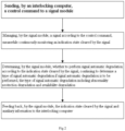
- FIG. 2 shows a schematic diagram of an automatic degradation method for a full electronic interlocking signal according to an embodiment of the present invention. As shown in FIG. 2 , the method includes:
- the abnormality protection degradation specifically is: directly converting, by the signal module, the signal to a safe indication state.
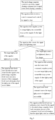
- FIG. 3 shows a flow chart of abnormality protection degradation according to an embodiment of the present invention, as shown in FIG. 3 :
- the availability degradation includes:
- the above-described availability degradation means that the signal module passively performs availability degradation.
- FIG. 4 shows a flow chart of passively performing availability degradation according to an embodiment of the present invention, as shown in FIG. 4 :
- the availability degradation further includes: directly and actively using, by the signal module, the signal lower-level clearing command to supply power to a new target light point of the signal, meanwhile stopping power supply of other light points of the signal.
- the availability degradation means that the signal module actively performs availability degradation, which is suitable for scenarios that require a response speed for availability degradation.
- FIG. 5 shows a flowchart of actively performing availability degradation which is not according to the invention and shown for illustration purposes only:
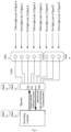
- FIG. 6 shows a schematic diagram of a system structure according to an embodiment of the present invention.
- the signal A there are five light points in the signal A, which sequentially are the yellow light point, the green light point, the red light point, the yellow light point, and the white light point; for railway lines having less information that need to indicate, the signal B can be used to direct traffic, there are three light points in the signal B, which sequentially are the green light point, the red light point, and the yellow light point.
- the interlocking computer sends commands and information to the signal module through the Ethernet, and the signal module controls the light point in the signal to indicate through the cable.
- light point setting of the above-described signal may also adopt other different types.
- indication of both the green light and the yellow light being concurrently cleared by the signal A is taken as an example, after receiving the command from the interlocking computer, the signal module cuts off power supply of other light points, meanwhile it supplies power to the yellow light, supplies power to the green light after the yellow light is lightened.
- the signal module feeds back to the interlocking computer an indication state that the green light and the yellow light are already cleared by the signal, feeds back execution success of the command, feeds back information that the light point is normal. After the green light and the yellow light are lightened, the signal module continuously monitors lightening of the light point.
- the signal module determines that the signal indication is abnormal and there is a safety risk, power supply to the yellow light and the green light is stopped immediately, power is supplied to the red light instead, meanwhile the signal module feeds back to the interlocking computer an indication state that the red light is cleared by the signal A, feeds back execution failure of the command, feeds back information that the yellow light point has a failure, so as to realize rapid protection against dangerous failure.
- the interlocking computer receives the failure information, switches the signal command to a red light command, and alarms the operation and maintenance personnel at the same time. After the green light and the yellow light are lightened, the signal module continuously monitors lightening of the light point. If the green light is found to be accidentally extinguished and the yellow light remains lightened, the interlocking computer only performs a corresponding availability degradation.
- the yellow light is defined as a lower-level signal command of the green light in practical applications.
- the signal module After receiving the command from the interlocking computer, the signal module cuts off power supply of other light points and meanwhile supplies power to the green light. After the green light is lightened, the signal module feeds back to the interlocking computer an indication state that the green light is already cleared by the signal, feeds back execution success of the command, feeds back information that the light point is normal. After the green light is lightened, the signal module continuously monitors lightening of the light point.
- the signal module feeds back to the interlocking computer an indication state that the signal A stops, feeds back execution failure of the command, feeds back information that the green light point has a failure.
- the interlocking computer receives the failure information, switches the signal command to a lower-level yellow light command, and alarms the operation and maintenance personnel at the same time; after the signal module receives the yellow light command, the signal module cuts off power supply of the green light and supplies power to the yellow light instead, after the yellow light is lightened, the signal module feeds back to the interlocking computer an indication state that the yellow light is already cleared by the signal, feeds back success execution of the command, and continues to feed back information that the green light has a failure.
- a wait time timing is set when the signal module is waiting for the interlocking computer to switch the command, the signal module actively lightens the prohibition light of the signal, the red light, if the interlocking computer does not switch the command after the timing ends.
- the signal module When the signal module actively performs availability degradation: For scenarios that require a response speed of availability degradation, when the interlocking computer sends a control command, it will also send a lower-level signal command as an additional command to the signal module, the signal module can directly and actively use the signal lower-level clearing command to lighten the new target light point.
- the yellow light is defined as a lower-level signal command of the green light in practical applications.
- the interlocking computer sends a green light clearing command to the signal module, it also sends a yellow light clearing command as an additional command to the signal module.
- the signal module cuts off power supply of other light points and supplies power to the green light.
- the signal module feeds back to the interlocking computer an indication state that the green light is already cleared by the signal, feeds back execution success of the command, feeds back information that the light point is normal.
- the signal module After the green light is lightened, the signal module continuously monitors lightening of the light point, the signal module will cut off power supply of the green light and start to supply power to the yellow light if the green light is found to be accidentally extinguished. After the yellow light is cleared, the signal module feeds back to the interlocking computer an indication state that the yellow light is cleared by the signal A, feeds back execution success of the command, feeds back information of that the green light point has a failure; the interlocking computer receives the signal information, switches the signal command to the lower-level yellow light command, and alarms the operation and maintenance personnel at the same time.
- the present invention further provides an automatic degradation system for a full electronic interlocking signal, as shown in FIG. 6 , the system includes an interlocking computer, a signal module, and a signal, wherein
- the interlocking computer and the signal module transmit information through the Ethernet, the interlocking computer sends control commands to the signal module through the Ethernet, the signal module feeds back an indication state cleared by the signal and auxiliary information to the interlocking computer through the Ethernet; the signal module is connected to the signal through the cable, and controls the light point in the signal to be lightened or extinguished.
- the present invention makes a division into abnormality protection degradation and availability degradation.
- abnormality protection degradation respond can be made quickly when danger indication is found, which improves the processing speed and avoids the time delay caused by a system failure or external factors;
- availability degradation degradation response time is reduced through an additional command mode, which improves safety and availability.
Landscapes
- Engineering & Computer Science (AREA)
- Mechanical Engineering (AREA)
- Physics & Mathematics (AREA)
- General Physics & Mathematics (AREA)
- Automation & Control Theory (AREA)
- Circuit Arrangement For Electric Light Sources In General (AREA)
- Controls And Circuits For Display Device (AREA)
- Train Traffic Observation, Control, And Security (AREA)
- Power Sources (AREA)
Description
- The present invention relates to the field of rail transport technology, and more particularly, to an automatic degradation method and system for a full electronic interlocking signal.
- The full electronic interlocking uses the signal control module instead of the traditional relay circuit to control clearing of the signal. The DS6-60 full electronic interlocking system adopts the prior mature interlocking computer of the DS6-60 system as the safe operation logic platform, and the full electronic modules (the signal module, the switch module, the universal input output module) as the execution unit to complete direct control over signal devices, the system structure is shown in
FIG. 1 . - The interlocking computer (the safe logic operation computer) sends a control command to the execution unit, the signal module executes the command to control a light point of the signal to be lightened or extinguished, meanwhile it sends the clearing state of the signal to the interlocking computer. When the clearing state of the signal is abnormal, for example, the interlocking computer requires the green light to be cleared by the signal, but the green light bulb cannot be lightened, the signal module will feed back to the interlocking computer that the green light cannot be lightened, the interlocking computer determines that the state does not meet expectations and then it changes the control command. Usually the signal module and the interlocking computer use Ethernet to communicate, there is a certain delay in the information exchange process, the delay time may be relatively long when the communication is interfered, especially when the signal fails in the case where the prohibition light needs to be lightened urgently (such as lightening a red light point), a too long delay time will seriously reduce safety and availability of the system.
- Therefore, how to control the signal to switch the signal state in time and improve safety and availability of the system has become an urgent problem to be solved.
- In view of the above problem, the present invention provides an automatic degradation method for a full electronic interlocking signal according to claim 1.
- Further, the control command includes: a signal clearing command, a signal lower-level clearing command, and a signal clearing command plus a signal lower-level clearing command.
- Further, managing, by the signal module, a signal according to the control command specifically is:
supplying, by the signal module, power to a target light point of the signal according to the control command, meanwhile stopping power supply of other light points of the signal. - Further, determining, by the signal module, whether to perform signal automatic degradation according to the indication state cleared by the signal specifically is:
- if the indication state cleared by the signal is normal indication, not performing signal automatic degradation;
- if the indication state cleared by the signal is abnormal indication or that optimal indication cannot be lightened normally, performing signal automatic degradation.
- Further, determining a type of signal automatic degradation specifically is:
- when the indication state cleared by the signal is abnormal indication, performing abnormality protection degradation;
- when the indication state cleared by the signal is that optimal indication cannot be normally lightened, performing availability degradation.
- Further, the abnormality protection degradation specifically is:
directly converting, by the signal module, the signal to a safe indication state. - Further, the availability degradation includes:
- feeding back, by the signal module, the indication state cleared by the signal to the interlocking computer;
- switching, by the interlocking computer, the control command to a signal lower-level clearing command according to the indication state cleared by the signal as received and sending it to the signal module;
- if the signal module receives the signal lower-level clearing command within a set time period, supplying, by the signal module, power to a new target light point of the signal according to the signal lower-level clearing command, meanwhile stopping power supply of other light points of the signal;
- if the signal module does not receive the signal lower-level clearing command within a set time period, lightening, by the signal module, a prohibition light point of the signal.
- Further, the availability degradation further includes:
directly and actively using, by the signal module, the signal lower-level clearing command to supply power to a new target light point of the signal, meanwhile stopping power supply of other light points of the signal. - Further, the auxiliary information includes command execution state and failure information.
- There is further provided an automatic degradation system for a full electronic interlocking signal according to claim 5.
- Further, the control command includes: a signal clearing command, a signal lower-level clearing command, and a signal clearing command plus a signal lower-level clearing command.
- Further, managing a signal according to the control command specifically is:
supplying, by the signal module, power to a target light point of the signal according to the control command, meanwhile stopping power supply of other light points of the signal. - Further, determining whether to perform signal automatic degradation according to the indication state cleared by the signal specifically is:
- if the indication state cleared by the signal is normal indication, not performing signal automatic degradation;
- if the indication state cleared by the signal is abnormal indication or that optimal indication cannot be lightened normally, performing signal automatic degradation.
- Further, determining a type of signal automatic degradation specifically is:
- when the indication state cleared by the signal is abnormal indication, performing abnormality protection degradation;
- when the indication state cleared by the signal is that optimal indication cannot be normally lightened, performing availability degradation.
- Further, the abnormality protection degradation specifically is:
directly converting, by the signal module, the signal to a safe indication state. - Further, the availability degradation includes:
- feeding back, by the signal module, the indication state cleared by the signal to the interlocking computer;
- switching, by the interlocking computer, the control command to a signal lower-level clearing command according to the indication state cleared by the signal as received and sending it to the signal module;
- if the signal module receives the signal lower-level clearing command within a set time period, supplying, by the signal module, power to a new target light point of the signal according to the signal lower-level clearing command, meanwhile stopping power supply of other light points of the signal;
- if the signal module does not receive the signal lower-level clearing command within a set time period, lightening, by the signal module, a prohibition light point of the signal.
- Further, the availability degradation further includes:
directly and actively using, by the signal module, the signal lower-level clearing command to supply power to a new target light point of the signal, meanwhile stopping power supply of other light points of the signal. - Further, the auxiliary information includes command execution state and failure information.
- By differentiating the degradation function, the present invention makes a division into abnormality protection degradation and availability degradation. For abnormality protection degradation, respond can be made quickly when danger indication is found, which improves the processing speed and avoids the time delay caused by a system failure or external factors; for availability degradation, degradation response time is reduced through an additional command mode, which improves safety and availability.
- Other features and advantages of the present invention will be discribed in the following description, some of them will become obvious from the description or will be understood by implementing the present invention. The objects and other advantages of the present invention can be realized and obtained through the structures indicated in the specification, claims and drawings.
- In order to more clearly illustrate the technical solutions in the embodiments of the present invention or in the prior art, the drawings necessary for description of the embodiments or the prior art will be briefly introduced below, obviously, the drawings in the following description are some embodiments of the present invention, other drawings can be obtained by those of ordinary skill in the art based on these drawings without paying creative efforts.
-
FIG. 1 shows a structure diagram of the DS6-60 full electronic interlocking system according to the prior art; -
FIG. 2 shows a schematic diagram of an automatic degradation method for a full electronic interlocking signal according to an embodiment of the present invention; -
FIG. 3 shows a flow chart of abnormality protection degradation according to an embodiment of the present invention; -
FIG. 4 shows a flow chart of passively performing availability degradation according to an embodiment of the present invention; -
FIG. 5 shows a flow chart of actively performing availability degradation not according to the invention and shown for illustration purposes only; -
FIG. 6 shows a schematic diagram of a system structure according to an embodiment of the present invention. - In order to make the objects, technical solutions and advantages of the embodiments of the present invention more clear, the technical solutions in the embodiments of the present invention will be described clearly and completely in conjunction with the accompanying drawings in the embodiments of the present invention, obviously, the described embodiments are only part of the embodiments of the present invention, not all the embodiments.
- The present invention provides an automatic degradation method for a full electronic interlocking signal, exemplarily,
FIG. 2 shows a schematic diagram of an automatic degradation method for a full electronic interlocking signal according to an embodiment of the present invention. As shown inFIG. 2 , the method includes: - sending, by an interlocking computer, a control command to a signal module;
- specifically, the control command includes: a signal clearing command, a signal lower-level clearing command, and a signal clearing command plus a signal lower-level clearing command;
- managing, by the signal module, a signal according to the control command, meanwhile continuously monitoring an indication state cleared by the signal;
- specifically, supplying, by the signal module, power to a target light point of the signal according to the control command, meanwhile stopping power supply of other light points of the signal.
- determining, by the signal module, whether to perform signal automatic degradation according to the indication state cleared by the signal, continuing to determine a type of signal automatic degradation if signal automatic degradation is to be performed, the type of signal automatic degradation including abnormality protection degradation and availability degradation; and feeding back, by the signal module, the indication state cleared by the signal and auxiliary information to the interlocking computer; wherein the auxiliary information includes command execution state and failure information;
- specifically, if the indication state cleared by the signal is normal indication, not performing signal automatic degradation;
- if the indication state cleared by the signal is abnormal indication or that optimal indication cannot be lightened normally, performing signal automatic degradation.
- further, when the indication state cleared by the signal is abnormal indication, performing abnormality protection degradation;
- when the indication state cleared by the signal is that optimal indication cannot be normally lightened, performing availability degradation.
- The abnormality protection degradation specifically is: directly converting, by the signal module, the signal to a safe indication state.
- Exemplarily,
FIG. 3 shows a flow chart of abnormality protection degradation according to an embodiment of the present invention, as shown inFIG. 3 : - S1: the interlocking computer controls to provide a signal clearing command, so as to control the signal to clear;
- S2: the signal module receives a control command and controls the signal to clear;
- S3: the signal module supplies power to a target light point, meanwhile stops power supply of other light points of the signal;
- S4: the signal module continuously monitors a light point lightening state of the signal;
- S51: the target light point of the signal is successfully lightened;
- S52: the signal module feeds back an indication state cleared by the signal to the interlocking computer, feeds back execution success of the command, feeds back information that the light point of the signal has no failure;
- S61: the indication state cleared by the signal is indication abnormality, that is, a danger light point of the signal is lightened;
- S62: the signal module immediately cuts off power supply of a relevant light point, and supplies power to a prohibition light point, converts the signal into a safe indication state;
- S63: the signal module feeds back the state that the prohibition light point is cleared by the signal to the interlocking computer, feeds back execution failure of the command, feeds back information that the signal light point has a failure.
- The availability degradation includes:
- feeding back, by the signal module, the indication state cleared by the signal to the interlocking computer;
- switching, by the interlocking computer, the control command to a signal lower-level clearing command according to the indication state cleared by the signal as received and sending it to the signal module;
- if the signal module receives the signal lower-level clearing command within a set time period, supplying, by the signal module, power to a new target light point of the signal according to the signal lower-level clearing command, meanwhile stopping power supply of other light points of the signal;
- if the signal module does not receive the signal lower-level clearing command within a set time period, lightening, by the signal module, a prohibition light point of the signal.
- The above-described availability degradation means that the signal module passively performs availability degradation.
- Exemplarily,
FIG. 4 shows a flow chart of passively performing availability degradation according to an embodiment of the present invention, as shown inFIG. 4 : - S1: the interlocking computer controls to provide a signal clearing command, so as to control the signal to clear;
- S2: the signal module receives a control command and controls the signal to clear;
- S3: the signal module supplies power to a target light point, meanwhile stops power supply of other light points;
- S4: the signal module continuously monitors a light point lightening state of the signal;
- S51: the target light point of the signal is successfully lightened;
- S52: the signal module feeds back an indication state cleared by the signal to the interlocking computer, feeds back execution success of the command, feeds back information that the light point of the signal has no failure;
- S61: optimal indication cannot be lightened, that is, the target light point is not lightened, there is no danger;
- S62: the signal module feeds back to the interlocking computer that the signal is in an at-stop state, feeds back execution failure of the command, feeds back information that the signal light point has a failure;
- S63: the interlocking computer provides a signal lower-level clearing command;
- S64: the signal module receives a new command and controls the signal to clear;
- S65: the signal module supplies power to a new target light point, meanwhile stops power supply of other light points;
- S66: the signal module checks a signal light point lightening state;
- S67: the target light point of the signal is successfully lightened;
- S68: the signal module feeds back an indication state cleared by the signal to the interlocking computer, feeds back execution success of the command, feeds back information that the signal light point has a failure.
- Alternatively not according to the invention, the availability degradation further includes:
directly and actively using, by the signal module, the signal lower-level clearing command to supply power to a new target light point of the signal, meanwhile stopping power supply of other light points of the signal. - As used herein, the availability degradation means that the signal module actively performs availability degradation, which is suitable for scenarios that require a response speed for availability degradation.
- Exemplarily,
FIG. 5 shows a flowchart of actively performing availability degradation which is not according to the invention and shown for illustration purposes only: - S1: the interlocking computer controls to provide a signal clearing command plus a signal lower-level clearing command, so as to control the signal to clear;
- S2: the signal module receives a control command and controls the signal to clear;
- S3: the signal module supplies power to a target light point, meanwhile stops power supply of other light points;
- S4: the signal module continuously monitors the signal light point lightening state;
- S51: the target light point of the signal is lightened successfully;
- S52: the signal module feeds back an indication state cleared by the signal to the interlocking computer, feeds back execution success of the command, feeds back information that the light point of the signal has no failure;
- S61: optimal indication cannot be lightened normally, that is, the target light point is not lightened, there is no danger;
- S62: the signal module actively uses the lower-level command, supplies power to a new target light point, meanwhile stops power supply of other light points of the signal;
- S63: the signal lower-level command causes the target light point to be lightened successfully;
- S64: the signal module feeds back an indication state cleared by the signal to the interlocking computer, feeds back execution success of the command, feeds back information that the signal light point has a failure.
- The embodiment of the present invention takes two signals as an example for description. Illustratively,
FIG. 6 shows a schematic diagram of a system structure according to an embodiment of the present invention. As shown inFIG. 6 , there are five light points in the signal A, which sequentially are the yellow light point, the green light point, the red light point, the yellow light point, and the white light point; for railway lines having less information that need to indicate, the signal B can be used to direct traffic, there are three light points in the signal B, which sequentially are the green light point, the red light point, and the yellow light point. The interlocking computer sends commands and information to the signal module through the Ethernet, and the signal module controls the light point in the signal to indicate through the cable. - It should be noted that light point setting of the above-described signal may also adopt other different types.
- Exemplarily, indication of both the green light and the yellow light being concurrently cleared by the signal A is taken as an example, after receiving the command from the interlocking computer, the signal module cuts off power supply of other light points, meanwhile it supplies power to the yellow light, supplies power to the green light after the yellow light is lightened. When both the green light and the yellow light are lightened, the signal module feeds back to the interlocking computer an indication state that the green light and the yellow light are already cleared by the signal, feeds back execution success of the command, feeds back information that the light point is normal. After the green light and the yellow light are lightened, the signal module continuously monitors lightening of the light point. If the yellow light is accidentally extinguished and the green light remains lightened, the signal module determines that the signal indication is abnormal and there is a safety risk, power supply to the yellow light and the green light is stopped immediately, power is supplied to the red light instead, meanwhile the signal module feeds back to the interlocking computer an indication state that the red light is cleared by the signal A, feeds back execution failure of the command, feeds back information that the yellow light point has a failure, so as to realize rapid protection against dangerous failure. Correspondingly, the interlocking computer receives the failure information, switches the signal command to a red light command, and alarms the operation and maintenance personnel at the same time. After the green light and the yellow light are lightened, the signal module continuously monitors lightening of the light point. If the green light is found to be accidentally extinguished and the yellow light remains lightened, the interlocking computer only performs a corresponding availability degradation.
- When the signal module passively performs availability degradation:
Exemplarily, indication of the green light being cleared by the signal A is taken as an example, the yellow light is defined as a lower-level signal command of the green light in practical applications. After receiving the command from the interlocking computer, the signal module cuts off power supply of other light points and meanwhile supplies power to the green light. After the green light is lightened, the signal module feeds back to the interlocking computer an indication state that the green light is already cleared by the signal, feeds back execution success of the command, feeds back information that the light point is normal. After the green light is lightened, the signal module continuously monitors lightening of the light point. If the green light is found to be accidentally extinguished, the signal module feeds back to the interlocking computer an indication state that the signal A stops, feeds back execution failure of the command, feeds back information that the green light point has a failure. The interlocking computer receives the failure information, switches the signal command to a lower-level yellow light command, and alarms the operation and maintenance personnel at the same time; after the signal module receives the yellow light command, the signal module cuts off power supply of the green light and supplies power to the yellow light instead, after the yellow light is lightened, the signal module feeds back to the interlocking computer an indication state that the yellow light is already cleared by the signal, feeds back success execution of the command, and continues to feed back information that the green light has a failure. A wait time timing is set when the signal module is waiting for the interlocking computer to switch the command, the signal module actively lightens the prohibition light of the signal, the red light, if the interlocking computer does not switch the command after the timing ends. - When the signal module actively performs availability degradation:
For scenarios that require a response speed of availability degradation, when the interlocking computer sends a control command, it will also send a lower-level signal command as an additional command to the signal module, the signal module can directly and actively use the signal lower-level clearing command to lighten the new target light point. - Exemplarily, taking that the green light is cleared by the signal A as an example, the yellow light is defined as a lower-level signal command of the green light in practical applications. When the interlocking computer sends a green light clearing command to the signal module, it also sends a yellow light clearing command as an additional command to the signal module. After receiving the command from the interlocking computer, the signal module cuts off power supply of other light points and supplies power to the green light. After the green light is lightened, the signal module feeds back to the interlocking computer an indication state that the green light is already cleared by the signal, feeds back execution success of the command, feeds back information that the light point is normal. After the green light is lightened, the signal module continuously monitors lightening of the light point, the signal module will cut off power supply of the green light and start to supply power to the yellow light if the green light is found to be accidentally extinguished. After the yellow light is cleared, the signal module feeds back to the interlocking computer an indication state that the yellow light is cleared by the signal A, feeds back execution success of the command, feeds back information of that the green light point has a failure; the interlocking computer receives the signal information, switches the signal command to the lower-level yellow light command, and alarms the operation and maintenance personnel at the same time.
- The present invention further provides an automatic degradation system for a full electronic interlocking signal, as shown in
FIG. 6 , the system includes an interlocking computer, a signal module, and a signal, wherein - the interlocking computer is for sending a control command to the signal module;
- the signal module is for managing a signal according to the control command, meanwhile continuously monitoring an indication state cleared by the signal, determining whether to perform signal automatic degradation according to the indication state cleared by the signal, and further feeding back the indication state cleared by the signal and auxiliary information to the interlocking computer.
- the signal is for signal indication.
- Specifically, the interlocking computer and the signal module transmit information through the Ethernet, the interlocking computer sends control commands to the signal module through the Ethernet, the signal module feeds back an indication state cleared by the signal and auxiliary information to the interlocking computer through the Ethernet; the signal module is connected to the signal through the cable, and controls the light point in the signal to be lightened or extinguished.
- By differentiating the degradation function, the present invention makes a division into abnormality protection degradation and availability degradation. For abnormality protection degradation, respond can be made quickly when danger indication is found, which improves the processing speed and avoids the time delay caused by a system failure or external factors; for availability degradation, degradation response time is reduced through an additional command mode, which improves safety and availability.
- Although the present invention has been described in detail with reference to the foregoing embodiments, those of ordinary skill in the art should understand that they can still modify the technical solutions described in the foregoing embodiments, or equivalently replace some of the technical features as long as these modifications do not deviate from the scope defined in the appended claims.
Claims (8)
- An automatic degradation method for a full electronic interlocking signal, comprising:sending, by an interlocking computer, a control command to a signal module;managing, by the signal module, a signal according to the control command, meanwhile continuously monitoring an indication state of the signal at clear;determining, by the signal module, whether to perform signal automatic degradation according to the indication state of the signal at clear,if it is determined to perform a signal automatic degradation, continuing to determine a type of signal automatic degradation, and performing the type of signal automatic degradation, including:when the indication state of the signal at clear is that the signal indication is abnormal and there is a safety risk, performing a first type of signal automatic degradation, wherein the first type of signal automatic degradation is directly converting, by the signal module, the signal to a safe indication state;when the indication state of the signal at clear is that the optimal indication cannot be normally lightened and there is no danger, performing a second type of signal automatic degradation, wherein the second type of signal automatic degradation including:feeding back, by the signal module, the indication state of the signal at clear to the interlocking computer;switching, by the interlocking computer, the control command to a command of lower-level clear signal according to the indication state of the signal at clear as received and sending it to the signal module;if the signal module receives the command of lower-level clear signal within a set time period, supplying, by the signal module, power to a new target light point of the signal according to the command of lower-level clear signal, meanwhile stopping power supply of other light points of the signal;if the signal module does not receive a command of lower-level clear signal within a set time period, lightening, by the signal module, a prohibition light point of the signal;feeding back, by the signal module, the indication state of the signal at clear and auxiliary information to the interlocking computer,wherein the auxiliary information includes command execution state and failure information.
- The automatic degradation method for a full electronic interlocking signal according to claim 1, wherein
the control command includes: a signal clearing command, a command of lower-level clear signal, or a signal clearing command plus a command of lower-level clear signal. - The automatic degradation method for a full electronic interlocking signal according to claim 1, wherein
managing, by the signal module, a signal according to the control command specifically is:
supplying, by the signal module, power to a target light point of the signal according to the control command, meanwhile stopping power supply of other light points of the signal. - The automatic degradation method for a full electronic interlocking signal according to claim 1, wherein
determining, by the signal module, whether to perform signal automatic degradation according to the indication state of the signal at clear specifically is:if the indication state of the signal at clear is normal indication, not performing signal automatic degradation;if the indication state of the signal at clear is abnormal indication or that the optimal indication cannot be lightened normally, performing signal automatic degradation. - An automatic degradation system for a full electronic interlocking signal, comprising:an interlocking computer configured to send a control command to a signal module;the signal module configured to manage a signal according to the control command, meanwhile configured to continuously monitor an indication state of the signal at clear, to determine whether to perform signal automatic degradation according to the indication state of the signal at clear, to continue to determine a type of signal automatic degradation if signal automatic degradation is to be performed, and to feed back the indication state of the signal at clear and auxiliary information to the interlocking computer,wherein the auxiliary information includes command execution state and failure information;wherein the signal module configured to determine a type of signal automatic degradation is that:when the indication state of the signal at clear is that the signal indication is abnormal and there is a safety risk, the signal module is configured to perform a first type of signal automatic degradation, including that the signal module is configured to directly convert the signal to a safe indication state;when the indication state of the signal at clear is that the optimal indication cannot be normally lightened and there is no danger, the signal module is configured to perform a second type of signal automatic degradation, including that:the signal module is configured to feed back the indication state of the signal at clear to the interlocking computer;the interlocking computer is configured to switch the control command to a command of lower-level clear signal according to the indication state of the signal at clear as received and to send it to the signal module;if the signal module receives the command of lower-level clear signal within a set time period, the signal module is configured to supply power to a new target light point of the signal according to the command of lower-level clear signal, meanwhile to stop power supply of other light points of the signal;if the signal module does not receive the command of lower-level clear signal within a set time period, the signal module is configured to lighten a prohibition light point of the signal.
- The automatic degradation system for a full electronic interlocking signal according to claim 5, wherein
the control command includes: a signal clearing command, a command of lower-level clear signal, or a signal clearing command plus a command of lower-level clear signal. - The automatic degradation system for a full electronic interlocking signal according to claim 5, wherein
the signal module configured to manage a signal according to the control command is that:
the signal module is configured to supply, by the signal module, power to a target light point of the signal according to the control command, meanwhile to stop power supply of other light points of the signal. - The automatic degradation system for a full electronic interlocking signal according to claim 5, whereinthe signal module configured to determine whether to perform signal automatic degradation according to the indication state of the signal at clear specifically is that:if the indication state of the signal at clear is normal indication, the signal module is configured not to perform signal automatic degradation;if the indication state of the signal at clear is abnormal indication or that optimal indication cannot be lightened normally, the signal module is configured to perform signal automatic degradation.
Priority Applications (1)
| Application Number | Priority Date | Filing Date | Title |
|---|---|---|---|
| RS20250428A RS66764B1 (en) | 2020-04-03 | 2020-08-14 | Signal automatic degrading method for fully electronic interlocking, and system |
Applications Claiming Priority (2)
| Application Number | Priority Date | Filing Date | Title |
|---|---|---|---|
| CN202010257259.XA CN111142507B (en) | 2020-04-03 | 2020-04-03 | Full-electronic interlocking signal automatic degradation method and system |
| PCT/CN2020/109263 WO2021196499A1 (en) | 2020-04-03 | 2020-08-14 | Signal automatic downgrade method for fully electronic interlocking, and system |
Publications (4)
| Publication Number | Publication Date |
|---|---|
| EP3910436A1 EP3910436A1 (en) | 2021-11-17 |
| EP3910436A4 EP3910436A4 (en) | 2022-04-20 |
| EP3910436C0 EP3910436C0 (en) | 2025-02-19 |
| EP3910436B1 true EP3910436B1 (en) | 2025-02-19 |
Family
ID=70528773
Family Applications (1)
| Application Number | Title | Priority Date | Filing Date |
|---|---|---|---|
| EP20785893.7A Active EP3910436B1 (en) | 2020-04-03 | 2020-08-14 | Signal automatic degrading method for fully electronic interlocking, and system |
Country Status (5)
| Country | Link |
|---|---|
| EP (1) | EP3910436B1 (en) |
| CN (1) | CN111142507B (en) |
| HU (1) | HUE070600T2 (en) |
| RS (1) | RS66764B1 (en) |
| WO (1) | WO2021196499A1 (en) |
Families Citing this family (6)
| Publication number | Priority date | Publication date | Assignee | Title |
|---|---|---|---|---|
| CN111142507B (en) * | 2020-04-03 | 2020-07-31 | 北京全路通信信号研究设计院集团有限公司 | Full-electronic interlocking signal automatic degradation method and system |
| CN115394092B (en) * | 2022-08-03 | 2024-03-12 | 卡斯柯信号有限公司 | A priority-based multi-lamp position signal driving method |
| CN115973221A (en) * | 2022-12-27 | 2023-04-18 | 合肥工大高科信息科技股份有限公司 | A combined control method, system, device and medium for a train signal machine |
| CN116039706A (en) * | 2023-02-24 | 2023-05-02 | 卡斯柯信号有限公司 | A signal control method and system |
| CN116001851B (en) * | 2023-03-24 | 2023-06-20 | 北京全路通信信号研究设计院集团有限公司 | Display method and device of console train annunciator in transition period |
| CN116923506B (en) * | 2023-06-09 | 2026-03-24 | 通号城市轨道交通技术有限公司 | Data Anomaly Detection Method and System for All-Electronic Modules |
Family Cites Families (12)
| Publication number | Priority date | Publication date | Assignee | Title |
|---|---|---|---|---|
| US5307050A (en) * | 1992-06-03 | 1994-04-26 | Honeywell Inc. | Display apparatus for a first out type of fault status annunciator having a series of interlock switches |
| JP4848991B2 (en) * | 2007-03-28 | 2011-12-28 | アイシン・エィ・ダブリュ株式会社 | Driving support method and driving support device |
| EP2030862A1 (en) * | 2007-08-30 | 2009-03-04 | Bombardier Transportation GmbH | Signal lamp arrangement for railway and other track bound traffic |
| CN102320316B (en) * | 2011-05-16 | 2013-10-09 | 铁道部运输局 | CTCS-3-level train control center system |
| CN103569161B (en) * | 2012-07-30 | 2015-11-04 | 北京西南交大盛阳科技有限公司 | Railway signals equipment based on comparing and logic analysis runs alarm method |
| CN104077922B (en) * | 2014-07-02 | 2016-07-13 | 杭州鼎鹏交通科技有限公司 | System and method for automatic fault detection and processing of traffic signal lights |
| CN204303170U (en) * | 2014-12-17 | 2015-04-29 | 上海宝康电子控制工程有限公司 | Automatic degradation monitoring treating apparatus |
| CN107993460A (en) * | 2017-11-29 | 2018-05-04 | 卡斯柯信号有限公司 | A kind of complexity level crossing tramcar signal priority control device and method |
| CN107831751B (en) * | 2017-12-05 | 2024-03-26 | 北京和利时系统工程有限公司 | All-electronic signal control module |
| CN108001483A (en) * | 2017-12-07 | 2018-05-08 | 通号万全信号设备有限公司 | A kind of Safty electronic drives framework |
| CN109270373A (en) * | 2018-09-14 | 2019-01-25 | 北京全路通信信号研究设计院集团有限公司 | Full-electronic interlocking test system and method |
| CN111142507B (en) * | 2020-04-03 | 2020-07-31 | 北京全路通信信号研究设计院集团有限公司 | Full-electronic interlocking signal automatic degradation method and system |
-
2020
- 2020-04-03 CN CN202010257259.XA patent/CN111142507B/en active Active
- 2020-08-14 RS RS20250428A patent/RS66764B1/en unknown
- 2020-08-14 EP EP20785893.7A patent/EP3910436B1/en active Active
- 2020-08-14 WO PCT/CN2020/109263 patent/WO2021196499A1/en not_active Ceased
- 2020-08-14 HU HUE20785893A patent/HUE070600T2/en unknown
Also Published As
| Publication number | Publication date |
|---|---|
| CN111142507B (en) | 2020-07-31 |
| EP3910436A4 (en) | 2022-04-20 |
| CN111142507A (en) | 2020-05-12 |
| RS66764B1 (en) | 2025-05-30 |
| EP3910436A1 (en) | 2021-11-17 |
| WO2021196499A1 (en) | 2021-10-07 |
| EP3910436C0 (en) | 2025-02-19 |
| HUE070600T2 (en) | 2025-06-28 |
Similar Documents
| Publication | Publication Date | Title |
|---|---|---|
| EP3910436A1 (en) | Signal automatic downgrade method for fully electronic interlocking, and system | |
| US11964677B2 (en) | Platform door control apparatus based on double 2-vote-2 architecture | |
| CN215244703U (en) | Automatic driving vehicle with multiple safety redundancy mechanisms and automatic driving system | |
| JP7114753B2 (en) | Multi-module optical fiber laser with real-time monitoring of optical module anomalies | |
| EP2101237B1 (en) | System for monitoring a plurality of sensors | |
| JP2000174706A (en) | Method and device for automatically controlling output power of optical signal | |
| CN110932645A (en) | High-voltage frequency converter dual-control machine redundancy topology structure and control method | |
| US7164965B2 (en) | Numerical controller and servomotor control system | |
| US20120224848A1 (en) | Optical fiber transmission system and power control method of the same | |
| CN118282842A (en) | Rail vehicle marshalling and reconnecting network system and fault processing method | |
| KR102016595B1 (en) | Smart LED Airfield Lighting with Built-in Communication Function | |
| JP5281566B2 (en) | Railway security system | |
| US20210257830A1 (en) | Method, device and system for protecting parallel-connected topology units | |
| CN112462594B (en) | 10M1553B bus controller backup method based on star topology | |
| OA20669A (en) | Automatic degradation method and system for full electronic interlocking signal. | |
| US20210119406A1 (en) | Multi-module fiber laser capable of monitoring abnormalities of optical modules in real time | |
| JP6252476B2 (en) | Multi-failure optical node, optical communication system using the same, and wavelength path switching method | |
| CN112874574A (en) | Distributed intelligent switch machine control system | |
| KR20200030822A (en) | Module for supplying power and system for supplying power | |
| KR102515332B1 (en) | Module for supplying power, system for supplying power and method for controlling system for supplying power | |
| CN113401169A (en) | Control method, device and system based on signal lamp control circuit | |
| CN116938628A (en) | Method and system for equipment redundancy synchronization switching of regional controller | |
| CN107623330A (en) | A kind of control method of valve base control system | |
| JP2004175186A (en) | Electronic interlocking device | |
| KR100673535B1 (en) | Transfer system and method by multiplexing information processing module of train track side |
Legal Events
| Date | Code | Title | Description |
|---|---|---|---|
| STAA | Information on the status of an ep patent application or granted ep patent |
Free format text: STATUS: UNKNOWN |
|
| STAA | Information on the status of an ep patent application or granted ep patent |
Free format text: STATUS: THE INTERNATIONAL PUBLICATION HAS BEEN MADE |
|
| PUAI | Public reference made under article 153(3) epc to a published international application that has entered the european phase |
Free format text: ORIGINAL CODE: 0009012 |
|
| STAA | Information on the status of an ep patent application or granted ep patent |
Free format text: STATUS: REQUEST FOR EXAMINATION WAS MADE |
|
| 17P | Request for examination filed |
Effective date: 20201014 |
|
| AK | Designated contracting states |
Kind code of ref document: A1 Designated state(s): AL AT BE BG CH CY CZ DE DK EE ES FI FR GB GR HR HU IE IS IT LI LT LU LV MC MK MT NL NO PL PT RO RS SE SI SK SM TR |
|
| A4 | Supplementary search report drawn up and despatched |
Effective date: 20220321 |
|
| RIC1 | Information provided on ipc code assigned before grant |
Ipc: B61L 5/18 20060101ALI20220315BHEP Ipc: B61L 27/16 20220101ALI20220315BHEP Ipc: B61L 7/10 20060101ALI20220315BHEP Ipc: G05B 23/02 20060101AFI20220315BHEP |
|
| DAV | Request for validation of the european patent (deleted) | ||
| DAX | Request for extension of the european patent (deleted) | ||
| GRAP | Despatch of communication of intention to grant a patent |
Free format text: ORIGINAL CODE: EPIDOSNIGR1 |
|
| STAA | Information on the status of an ep patent application or granted ep patent |
Free format text: STATUS: GRANT OF PATENT IS INTENDED |
|
| INTG | Intention to grant announced |
Effective date: 20240919 |
|
| GRAS | Grant fee paid |
Free format text: ORIGINAL CODE: EPIDOSNIGR3 |
|
| GRAA | (expected) grant |
Free format text: ORIGINAL CODE: 0009210 |
|
| STAA | Information on the status of an ep patent application or granted ep patent |
Free format text: STATUS: THE PATENT HAS BEEN GRANTED |
|
| AK | Designated contracting states |
Kind code of ref document: B1 Designated state(s): AL AT BE BG CH CY CZ DE DK EE ES FI FR GB GR HR HU IE IS IT LI LT LU LV MC MK MT NL NO PL PT RO RS SE SI SK SM TR |
|
| REG | Reference to a national code |
Ref country code: GB Ref legal event code: FG4D |
|
| REG | Reference to a national code |
Ref country code: CH Ref legal event code: EP |
|
| REG | Reference to a national code |
Ref country code: IE Ref legal event code: FG4D |
|
| REG | Reference to a national code |
Ref country code: DE Ref legal event code: R096 Ref document number: 602020046368 Country of ref document: DE |
|
| U01 | Request for unitary effect filed |
Effective date: 20250311 |
|
| U07 | Unitary effect registered |
Designated state(s): AT BE BG DE DK EE FI FR IT LT LU LV MT NL PT RO SE SI Effective date: 20250319 |
|
| REG | Reference to a national code |
Ref country code: HU Ref legal event code: AG4A Ref document number: E070600 Country of ref document: HU |
|
| PG25 | Lapsed in a contracting state [announced via postgrant information from national office to epo] |
Ref country code: PL Free format text: LAPSE BECAUSE OF FAILURE TO SUBMIT A TRANSLATION OF THE DESCRIPTION OR TO PAY THE FEE WITHIN THE PRESCRIBED TIME-LIMIT Effective date: 20250219 |
|
| PG25 | Lapsed in a contracting state [announced via postgrant information from national office to epo] |
Ref country code: ES Free format text: LAPSE BECAUSE OF FAILURE TO SUBMIT A TRANSLATION OF THE DESCRIPTION OR TO PAY THE FEE WITHIN THE PRESCRIBED TIME-LIMIT Effective date: 20250219 |
|
| PG25 | Lapsed in a contracting state [announced via postgrant information from national office to epo] |
Ref country code: NO Free format text: LAPSE BECAUSE OF FAILURE TO SUBMIT A TRANSLATION OF THE DESCRIPTION OR TO PAY THE FEE WITHIN THE PRESCRIBED TIME-LIMIT Effective date: 20250519 Ref country code: IS Free format text: LAPSE BECAUSE OF FAILURE TO SUBMIT A TRANSLATION OF THE DESCRIPTION OR TO PAY THE FEE WITHIN THE PRESCRIBED TIME-LIMIT Effective date: 20250619 |
|
| PG25 | Lapsed in a contracting state [announced via postgrant information from national office to epo] |
Ref country code: HR Free format text: LAPSE BECAUSE OF FAILURE TO SUBMIT A TRANSLATION OF THE DESCRIPTION OR TO PAY THE FEE WITHIN THE PRESCRIBED TIME-LIMIT Effective date: 20250219 |
|
| PG25 | Lapsed in a contracting state [announced via postgrant information from national office to epo] |
Ref country code: GR Free format text: LAPSE BECAUSE OF FAILURE TO SUBMIT A TRANSLATION OF THE DESCRIPTION OR TO PAY THE FEE WITHIN THE PRESCRIBED TIME-LIMIT Effective date: 20250520 |
|
| U20 | Renewal fee for the european patent with unitary effect paid |
Year of fee payment: 6 Effective date: 20250709 |
|
| PGFP | Annual fee paid to national office [announced via postgrant information from national office to epo] |
Ref country code: HU Payment date: 20250827 Year of fee payment: 6 |
|
| PG25 | Lapsed in a contracting state [announced via postgrant information from national office to epo] |
Ref country code: SM Free format text: LAPSE BECAUSE OF FAILURE TO SUBMIT A TRANSLATION OF THE DESCRIPTION OR TO PAY THE FEE WITHIN THE PRESCRIBED TIME-LIMIT Effective date: 20250219 |
|
| PG25 | Lapsed in a contracting state [announced via postgrant information from national office to epo] |
Ref country code: CZ Free format text: LAPSE BECAUSE OF FAILURE TO SUBMIT A TRANSLATION OF THE DESCRIPTION OR TO PAY THE FEE WITHIN THE PRESCRIBED TIME-LIMIT Effective date: 20250219 |
|
| PGFP | Annual fee paid to national office [announced via postgrant information from national office to epo] |
Ref country code: RS Payment date: 20250704 Year of fee payment: 6 |
|
| PG25 | Lapsed in a contracting state [announced via postgrant information from national office to epo] |
Ref country code: SK Free format text: LAPSE BECAUSE OF FAILURE TO SUBMIT A TRANSLATION OF THE DESCRIPTION OR TO PAY THE FEE WITHIN THE PRESCRIBED TIME-LIMIT Effective date: 20250219 |
|
| PLBE | No opposition filed within time limit |
Free format text: ORIGINAL CODE: 0009261 |
|
| STAA | Information on the status of an ep patent application or granted ep patent |
Free format text: STATUS: NO OPPOSITION FILED WITHIN TIME LIMIT |
|
| REG | Reference to a national code |
Ref country code: CH Ref legal event code: L10 Free format text: ST27 STATUS EVENT CODE: U-0-0-L10-L00 (AS PROVIDED BY THE NATIONAL OFFICE) Effective date: 20251231 |
|
| 26N | No opposition filed |
Effective date: 20251120 |
|
| REG | Reference to a national code |
Ref country code: CH Ref legal event code: H13 Free format text: ST27 STATUS EVENT CODE: U-0-0-H10-H13 (AS PROVIDED BY THE NATIONAL OFFICE) Effective date: 20260324 |
|
| PG25 | Lapsed in a contracting state [announced via postgrant information from national office to epo] |
Ref country code: MC Free format text: LAPSE BECAUSE OF FAILURE TO SUBMIT A TRANSLATION OF THE DESCRIPTION OR TO PAY THE FEE WITHIN THE PRESCRIBED TIME-LIMIT Effective date: 20250219 |
|
| PG25 | Lapsed in a contracting state [announced via postgrant information from national office to epo] |
Ref country code: CH Free format text: LAPSE BECAUSE OF NON-PAYMENT OF DUE FEES Effective date: 20250831 |
|
| GBPC | Gb: european patent ceased through non-payment of renewal fee |
Effective date: 20250814 |