EP3910433A1 - Methods of performing a plurality of operations within a region of a part utilizing an end effector of a robot and robots that perform the methods - Google Patents
Methods of performing a plurality of operations within a region of a part utilizing an end effector of a robot and robots that perform the methods Download PDFInfo
- Publication number
- EP3910433A1 EP3910433A1 EP21170172.7A EP21170172A EP3910433A1 EP 3910433 A1 EP3910433 A1 EP 3910433A1 EP 21170172 A EP21170172 A EP 21170172A EP 3910433 A1 EP3910433 A1 EP 3910433A1
- Authority
- EP
- European Patent Office
- Prior art keywords
- predetermined
- raster scan
- scan pattern
- end effector
- defining
- Prior art date
- Legal status (The legal status is an assumption and is not a legal conclusion. Google has not performed a legal analysis and makes no representation as to the accuracy of the status listed.)
- Granted
Links
Images




Classifications
-
- G—PHYSICS
- G05—CONTROLLING; REGULATING
- G05B—CONTROL OR REGULATING SYSTEMS IN GENERAL; FUNCTIONAL ELEMENTS OF SUCH SYSTEMS; MONITORING OR TESTING ARRANGEMENTS FOR SUCH SYSTEMS OR ELEMENTS
- G05B19/00—Program-control systems
- G05B19/02—Program-control systems electric
- G05B19/18—Numerical control [NC], i.e. automatically operating machines, in particular machine tools, e.g. in a manufacturing environment, so as to execute positioning, movement or co-ordinated operations by means of program data in numerical form
- G05B19/401—Numerical control [NC], i.e. automatically operating machines, in particular machine tools, e.g. in a manufacturing environment, so as to execute positioning, movement or co-ordinated operations by means of program data in numerical form characterised by control arrangements for measuring, e.g. calibration and initialisation, measuring workpiece for machining purposes
-
- B—PERFORMING OPERATIONS; TRANSPORTING
- B25—HAND TOOLS; PORTABLE POWER-DRIVEN TOOLS; MANIPULATORS
- B25J—MANIPULATORS; CHAMBERS PROVIDED WITH MANIPULATION DEVICES
- B25J9/00—Program-controlled manipulators
- B25J9/16—Program controls
-
- B—PERFORMING OPERATIONS; TRANSPORTING
- B25—HAND TOOLS; PORTABLE POWER-DRIVEN TOOLS; MANIPULATORS
- B25J—MANIPULATORS; CHAMBERS PROVIDED WITH MANIPULATION DEVICES
- B25J11/00—Manipulators not otherwise provided for
-
- B—PERFORMING OPERATIONS; TRANSPORTING
- B25—HAND TOOLS; PORTABLE POWER-DRIVEN TOOLS; MANIPULATORS
- B25J—MANIPULATORS; CHAMBERS PROVIDED WITH MANIPULATION DEVICES
- B25J15/00—Gripping heads and other end effectors
- B25J15/0019—End effectors other than grippers
-
- B—PERFORMING OPERATIONS; TRANSPORTING
- B25—HAND TOOLS; PORTABLE POWER-DRIVEN TOOLS; MANIPULATORS
- B25J—MANIPULATORS; CHAMBERS PROVIDED WITH MANIPULATION DEVICES
- B25J19/00—Accessories fitted to manipulators, e.g. for monitoring, for viewing; Safety devices combined with or specially adapted for use in connection with manipulators
- B25J19/02—Sensing devices
- B25J19/021—Optical sensing devices
-
- B—PERFORMING OPERATIONS; TRANSPORTING
- B25—HAND TOOLS; PORTABLE POWER-DRIVEN TOOLS; MANIPULATORS
- B25J—MANIPULATORS; CHAMBERS PROVIDED WITH MANIPULATION DEVICES
- B25J9/00—Program-controlled manipulators
- B25J9/02—Program-controlled manipulators characterised by movement of the arms, e.g. cartesian coordinate type
- B25J9/04—Program-controlled manipulators characterised by movement of the arms, e.g. cartesian coordinate type by rotating at least one arm, excluding the head movement itself, e.g. cylindrical coordinate type or polar coordinate type
- B25J9/041—Cylindrical coordinate type
-
- B—PERFORMING OPERATIONS; TRANSPORTING
- B25—HAND TOOLS; PORTABLE POWER-DRIVEN TOOLS; MANIPULATORS
- B25J—MANIPULATORS; CHAMBERS PROVIDED WITH MANIPULATION DEVICES
- B25J9/00—Program-controlled manipulators
- B25J9/16—Program controls
- B25J9/1612—Program controls characterised by the hand, wrist, grip control
-
- B—PERFORMING OPERATIONS; TRANSPORTING
- B25—HAND TOOLS; PORTABLE POWER-DRIVEN TOOLS; MANIPULATORS
- B25J—MANIPULATORS; CHAMBERS PROVIDED WITH MANIPULATION DEVICES
- B25J9/00—Program-controlled manipulators
- B25J9/16—Program controls
- B25J9/1679—Program controls characterised by the tasks executed
-
- B—PERFORMING OPERATIONS; TRANSPORTING
- B25—HAND TOOLS; PORTABLE POWER-DRIVEN TOOLS; MANIPULATORS
- B25J—MANIPULATORS; CHAMBERS PROVIDED WITH MANIPULATION DEVICES
- B25J9/00—Program-controlled manipulators
- B25J9/16—Program controls
- B25J9/1679—Program controls characterised by the tasks executed
- B25J9/1684—Tracking a line or surface by means of sensors
-
- B—PERFORMING OPERATIONS; TRANSPORTING
- B25—HAND TOOLS; PORTABLE POWER-DRIVEN TOOLS; MANIPULATORS
- B25J—MANIPULATORS; CHAMBERS PROVIDED WITH MANIPULATION DEVICES
- B25J9/00—Program-controlled manipulators
- B25J9/16—Program controls
- B25J9/1694—Program controls characterised by use of sensors other than normal servo-feedback from position, speed or acceleration sensors, perception control, multi-sensor controlled systems, sensor fusion
-
- B—PERFORMING OPERATIONS; TRANSPORTING
- B25—HAND TOOLS; PORTABLE POWER-DRIVEN TOOLS; MANIPULATORS
- B25J—MANIPULATORS; CHAMBERS PROVIDED WITH MANIPULATION DEVICES
- B25J9/00—Program-controlled manipulators
- B25J9/16—Program controls
- B25J9/1694—Program controls characterised by use of sensors other than normal servo-feedback from position, speed or acceleration sensors, perception control, multi-sensor controlled systems, sensor fusion
- B25J9/1697—Vision controlled systems
-
- B—PERFORMING OPERATIONS; TRANSPORTING
- B64—AIRCRAFT; AVIATION; COSMONAUTICS
- B64F—GROUND OR AIRCRAFT-CARRIER-DECK INSTALLATIONS SPECIALLY ADAPTED FOR USE IN CONNECTION WITH AIRCRAFT; DESIGNING, MANUFACTURING, ASSEMBLING, CLEANING, MAINTAINING OR REPAIRING AIRCRAFT, NOT OTHERWISE PROVIDED FOR; HANDLING, TRANSPORTING, TESTING OR INSPECTING AIRCRAFT COMPONENTS, NOT OTHERWISE PROVIDED FOR
- B64F5/00—Designing, manufacturing, assembling, cleaning, maintaining or repairing aircraft, not otherwise provided for; Handling, transporting, testing or inspecting aircraft components, not otherwise provided for
- B64F5/10—Manufacturing or assembling aircraft, e.g. jigs therefor
-
- B—PERFORMING OPERATIONS; TRANSPORTING
- B64—AIRCRAFT; AVIATION; COSMONAUTICS
- B64F—GROUND OR AIRCRAFT-CARRIER-DECK INSTALLATIONS SPECIALLY ADAPTED FOR USE IN CONNECTION WITH AIRCRAFT; DESIGNING, MANUFACTURING, ASSEMBLING, CLEANING, MAINTAINING OR REPAIRING AIRCRAFT, NOT OTHERWISE PROVIDED FOR; HANDLING, TRANSPORTING, TESTING OR INSPECTING AIRCRAFT COMPONENTS, NOT OTHERWISE PROVIDED FOR
- B64F5/00—Designing, manufacturing, assembling, cleaning, maintaining or repairing aircraft, not otherwise provided for; Handling, transporting, testing or inspecting aircraft components, not otherwise provided for
- B64F5/60—Testing or inspecting aircraft components or systems
-
- G—PHYSICS
- G01—MEASURING; TESTING
- G01B—MEASURING LENGTH, THICKNESS OR SIMILAR LINEAR DIMENSIONS; MEASURING ANGLES; MEASURING AREAS; MEASURING IRREGULARITIES OF SURFACES OR CONTOURS
- G01B17/00—Measuring arrangements characterised by the use of infrasonic, sonic or ultrasonic vibrations
- G01B17/02—Measuring arrangements characterised by the use of infrasonic, sonic or ultrasonic vibrations for measuring thickness
- G01B17/025—Measuring arrangements characterised by the use of infrasonic, sonic or ultrasonic vibrations for measuring thickness for measuring thickness of coating
-
- G—PHYSICS
- G01—MEASURING; TESTING
- G01N—INVESTIGATING OR ANALYSING MATERIALS BY DETERMINING THEIR CHEMICAL OR PHYSICAL PROPERTIES
- G01N29/00—Investigating or analysing materials by the use of ultrasonic, sonic or infrasonic waves; Visualisation of the interior of objects by transmitting ultrasonic or sonic waves through the object
- G01N29/02—Analysing fluids
-
- G—PHYSICS
- G01—MEASURING; TESTING
- G01N—INVESTIGATING OR ANALYSING MATERIALS BY DETERMINING THEIR CHEMICAL OR PHYSICAL PROPERTIES
- G01N29/00—Investigating or analysing materials by the use of ultrasonic, sonic or infrasonic waves; Visualisation of the interior of objects by transmitting ultrasonic or sonic waves through the object
- G01N29/04—Analysing solids
- G01N29/041—Analysing solids on the surface of the material, e.g. using Lamb, Rayleigh or shear waves
-
- G—PHYSICS
- G01—MEASURING; TESTING
- G01N—INVESTIGATING OR ANALYSING MATERIALS BY DETERMINING THEIR CHEMICAL OR PHYSICAL PROPERTIES
- G01N29/00—Investigating or analysing materials by the use of ultrasonic, sonic or infrasonic waves; Visualisation of the interior of objects by transmitting ultrasonic or sonic waves through the object
- G01N29/22—Details, e.g. general constructional or apparatus details
- G01N29/24—Probes
- G01N29/2418—Probes using optoacoustic interaction with the material, e.g. laser radiation, photoacoustics
-
- G—PHYSICS
- G01—MEASURING; TESTING
- G01N—INVESTIGATING OR ANALYSING MATERIALS BY DETERMINING THEIR CHEMICAL OR PHYSICAL PROPERTIES
- G01N29/00—Investigating or analysing materials by the use of ultrasonic, sonic or infrasonic waves; Visualisation of the interior of objects by transmitting ultrasonic or sonic waves through the object
- G01N29/22—Details, e.g. general constructional or apparatus details
- G01N29/24—Probes
- G01N29/2437—Piezoelectric probes
-
- G—PHYSICS
- G01—MEASURING; TESTING
- G01N—INVESTIGATING OR ANALYSING MATERIALS BY DETERMINING THEIR CHEMICAL OR PHYSICAL PROPERTIES
- G01N29/00—Investigating or analysing materials by the use of ultrasonic, sonic or infrasonic waves; Visualisation of the interior of objects by transmitting ultrasonic or sonic waves through the object
- G01N29/22—Details, e.g. general constructional or apparatus details
- G01N29/24—Probes
- G01N29/2462—Probes with waveguides, e.g. SAW devices
-
- G—PHYSICS
- G01—MEASURING; TESTING
- G01N—INVESTIGATING OR ANALYSING MATERIALS BY DETERMINING THEIR CHEMICAL OR PHYSICAL PROPERTIES
- G01N29/00—Investigating or analysing materials by the use of ultrasonic, sonic or infrasonic waves; Visualisation of the interior of objects by transmitting ultrasonic or sonic waves through the object
- G01N29/22—Details, e.g. general constructional or apparatus details
- G01N29/26—Arrangements for orientation or scanning by relative movement of the head and the sensor
-
- G—PHYSICS
- G01—MEASURING; TESTING
- G01N—INVESTIGATING OR ANALYSING MATERIALS BY DETERMINING THEIR CHEMICAL OR PHYSICAL PROPERTIES
- G01N29/00—Investigating or analysing materials by the use of ultrasonic, sonic or infrasonic waves; Visualisation of the interior of objects by transmitting ultrasonic or sonic waves through the object
- G01N29/34—Generating the ultrasonic, sonic or infrasonic waves, e.g. electronic circuits specially adapted therefor
-
- G—PHYSICS
- G01—MEASURING; TESTING
- G01N—INVESTIGATING OR ANALYSING MATERIALS BY DETERMINING THEIR CHEMICAL OR PHYSICAL PROPERTIES
- G01N29/00—Investigating or analysing materials by the use of ultrasonic, sonic or infrasonic waves; Visualisation of the interior of objects by transmitting ultrasonic or sonic waves through the object
- G01N29/44—Processing the detected response signal, e.g. electronic circuits specially adapted therefor
- G01N29/4454—Signal recognition, e.g. specific values or portions, signal events, signatures
-
- G—PHYSICS
- G05—CONTROLLING; REGULATING
- G05B—CONTROL OR REGULATING SYSTEMS IN GENERAL; FUNCTIONAL ELEMENTS OF SUCH SYSTEMS; MONITORING OR TESTING ARRANGEMENTS FOR SUCH SYSTEMS OR ELEMENTS
- G05B19/00—Program-control systems
- G05B19/02—Program-control systems electric
- G05B19/18—Numerical control [NC], i.e. automatically operating machines, in particular machine tools, e.g. in a manufacturing environment, so as to execute positioning, movement or co-ordinated operations by means of program data in numerical form
- G05B19/402—Numerical control [NC], i.e. automatically operating machines, in particular machine tools, e.g. in a manufacturing environment, so as to execute positioning, movement or co-ordinated operations by means of program data in numerical form characterised by control arrangements for positioning, e.g. centring a tool relative to a hole in the workpiece, additional detection means to correct position
-
- G—PHYSICS
- G05—CONTROLLING; REGULATING
- G05B—CONTROL OR REGULATING SYSTEMS IN GENERAL; FUNCTIONAL ELEMENTS OF SUCH SYSTEMS; MONITORING OR TESTING ARRANGEMENTS FOR SUCH SYSTEMS OR ELEMENTS
- G05B19/00—Program-control systems
- G05B19/02—Program-control systems electric
- G05B19/18—Numerical control [NC], i.e. automatically operating machines, in particular machine tools, e.g. in a manufacturing environment, so as to execute positioning, movement or co-ordinated operations by means of program data in numerical form
- G05B19/4155—Numerical control [NC], i.e. automatically operating machines, in particular machine tools, e.g. in a manufacturing environment, so as to execute positioning, movement or co-ordinated operations by means of program data in numerical form characterised by program execution, i.e. part program or machine function execution, e.g. selection of a program
-
- G—PHYSICS
- G06—COMPUTING OR CALCULATING; COUNTING
- G06N—COMPUTING ARRANGEMENTS BASED ON SPECIFIC COMPUTATIONAL MODELS
- G06N20/00—Machine learning
-
- G—PHYSICS
- G06—COMPUTING OR CALCULATING; COUNTING
- G06T—IMAGE DATA PROCESSING OR GENERATION, IN GENERAL
- G06T7/00—Image analysis
- G06T7/0002—Inspection of images, e.g. flaw detection
- G06T7/0004—Industrial image inspection
- G06T7/001—Industrial image inspection using an image reference approach
-
- G—PHYSICS
- G06—COMPUTING OR CALCULATING; COUNTING
- G06T—IMAGE DATA PROCESSING OR GENERATION, IN GENERAL
- G06T7/00—Image analysis
- G06T7/30—Determination of transform parameters for the alignment of images, i.e. image registration
- G06T7/33—Determination of transform parameters for the alignment of images, i.e. image registration using feature-based methods
-
- G—PHYSICS
- G06—COMPUTING OR CALCULATING; COUNTING
- G06T—IMAGE DATA PROCESSING OR GENERATION, IN GENERAL
- G06T7/00—Image analysis
- G06T7/70—Determining position or orientation of objects or cameras
- G06T7/73—Determining position or orientation of objects or cameras using feature-based methods
- G06T7/74—Determining position or orientation of objects or cameras using feature-based methods involving reference images or patches
-
- G—PHYSICS
- G05—CONTROLLING; REGULATING
- G05B—CONTROL OR REGULATING SYSTEMS IN GENERAL; FUNCTIONAL ELEMENTS OF SUCH SYSTEMS; MONITORING OR TESTING ARRANGEMENTS FOR SUCH SYSTEMS OR ELEMENTS
- G05B2219/00—Program-control systems
- G05B2219/30—Nc systems
- G05B2219/37—Measurements
- G05B2219/37108—Rasters, grid on xy-plane
-
- G—PHYSICS
- G05—CONTROLLING; REGULATING
- G05B—CONTROL OR REGULATING SYSTEMS IN GENERAL; FUNCTIONAL ELEMENTS OF SUCH SYSTEMS; MONITORING OR TESTING ARRANGEMENTS FOR SUCH SYSTEMS OR ELEMENTS
- G05B2219/00—Program-control systems
- G05B2219/30—Nc systems
- G05B2219/37—Measurements
- G05B2219/37208—Vision, visual inspection of workpiece
-
- G—PHYSICS
- G05—CONTROLLING; REGULATING
- G05B—CONTROL OR REGULATING SYSTEMS IN GENERAL; FUNCTIONAL ELEMENTS OF SUCH SYSTEMS; MONITORING OR TESTING ARRANGEMENTS FOR SUCH SYSTEMS OR ELEMENTS
- G05B2219/00—Program-control systems
- G05B2219/30—Nc systems
- G05B2219/37—Measurements
- G05B2219/37555—Camera detects orientation, position workpiece, points of workpiece
-
- G—PHYSICS
- G05—CONTROLLING; REGULATING
- G05B—CONTROL OR REGULATING SYSTEMS IN GENERAL; FUNCTIONAL ELEMENTS OF SUCH SYSTEMS; MONITORING OR TESTING ARRANGEMENTS FOR SUCH SYSTEMS OR ELEMENTS
- G05B2219/00—Program-control systems
- G05B2219/30—Nc systems
- G05B2219/39—Robotics, robotics to robotics hand
- G05B2219/39006—Move end effector in a plane, describing a raster, meander
-
- G—PHYSICS
- G05—CONTROLLING; REGULATING
- G05B—CONTROL OR REGULATING SYSTEMS IN GENERAL; FUNCTIONAL ELEMENTS OF SUCH SYSTEMS; MONITORING OR TESTING ARRANGEMENTS FOR SUCH SYSTEMS OR ELEMENTS
- G05B2219/00—Program-control systems
- G05B2219/30—Nc systems
- G05B2219/45—Nc applications
- G05B2219/45066—Inspection robot
-
- G—PHYSICS
- G05—CONTROLLING; REGULATING
- G05B—CONTROL OR REGULATING SYSTEMS IN GENERAL; FUNCTIONAL ELEMENTS OF SUCH SYSTEMS; MONITORING OR TESTING ARRANGEMENTS FOR SUCH SYSTEMS OR ELEMENTS
- G05B2219/00—Program-control systems
- G05B2219/30—Nc systems
- G05B2219/49—Nc machine tool, till multiple
- G05B2219/49112—Compensation alignment of cylindrical workpiece
-
- G—PHYSICS
- G05—CONTROLLING; REGULATING
- G05B—CONTROL OR REGULATING SYSTEMS IN GENERAL; FUNCTIONAL ELEMENTS OF SUCH SYSTEMS; MONITORING OR TESTING ARRANGEMENTS FOR SUCH SYSTEMS OR ELEMENTS
- G05B2219/00—Program-control systems
- G05B2219/30—Nc systems
- G05B2219/50—Machine tool, machine tool null till machine tool work handling
- G05B2219/50356—Tool perpendicular, normal to 3-D surface
-
- G—PHYSICS
- G05—CONTROLLING; REGULATING
- G05B—CONTROL OR REGULATING SYSTEMS IN GENERAL; FUNCTIONAL ELEMENTS OF SUCH SYSTEMS; MONITORING OR TESTING ARRANGEMENTS FOR SUCH SYSTEMS OR ELEMENTS
- G05B2219/00—Program-control systems
- G05B2219/30—Nc systems
- G05B2219/50—Machine tool, machine tool null till machine tool work handling
- G05B2219/50391—Robot
-
- G—PHYSICS
- G06—COMPUTING OR CALCULATING; COUNTING
- G06T—IMAGE DATA PROCESSING OR GENERATION, IN GENERAL
- G06T2207/00—Indexing scheme for image analysis or image enhancement
- G06T2207/30—Subject of image; Context of image processing
- G06T2207/30108—Industrial image inspection
- G06T2207/30164—Workpiece; Machine component
Definitions
- the present disclosure relates generally to methods of performing a plurality of operations within a region of a part utilizing an end effector of a robot and/or to robots that perform the methods.
- Robots may be utilized to perform a variety of different operations with and/or on a part.
- robots may be utilized to assemble one or more components of an aircraft.
- robots are effective at performing operations on a part with a well-defined, and quantitatively known, geometry.
- numeric descriptions of the part may be provided to the robot, and the robot may utilize this information to control motion of the robot, locations at which the operations are performed, and the like.
- Utilizing a robot on parts, or in environments, that are not well-defined and quantitatively known presents unique operational challenges and may increase costs substantially.
- it may be necessary to manually train the robot to navigate to various locations on the part and/or to perform desired operations at the various locations.
- the methods include collecting a spatial representation of the part.
- the collecting may include collecting with an imaging device that may be associated with the robot.
- the methods also include aligning a predetermined raster scan pattern for movement of the end effector relative to the part with the spatial representation of the part.
- the methods further include defining a plurality of normality vectors for the part at a plurality of predetermined operation locations for operation of the end effector. The defining may be based, at least in part, on the spatial representation of the part, and each operation location may be defined along the predetermined raster scan pattern.
- the methods also include moving the end effector relative to the part and along the predetermined raster scan pattern.
- the methods further include orienting the end effector such that an operation device of the end effector faces toward each operation location along a corresponding normality vector.
- the methods also include executing a corresponding operation of the plurality of operations with the operation device and at each operation location.
- Figs. 1-12 provide illustrative, non-exclusive examples of robots 10 that include end effectors 20 and/or of methods 300, according to the present disclosure. Elements that serve a similar, or at least substantially similar, purpose are labeled with like numbers in each of Figs. 1-12 , and these elements may not be discussed in detail herein with reference to each of Figs. 1-12 . Similarly, all elements may not be labeled in each of Figs. 1-12 , but reference numerals associated therewith may be utilized herein for consistency. Elements, components, and/or features that are discussed herein with reference to one or more of Figs. 1-12 may be included in and/or utilized with any of Figs. 1-12 without departing from the scope of the present disclosure.
- Fig. 1 is a schematic illustration of an example of an aircraft 700 that may be utilized with the robots (such as robot 10 as shown in Fig. 3 ) and/or methods (such as methods 300 as shown in Fig. 3 ) according to the present disclosure
- Fig. 2 is a schematic illustration of an example of a wing 740 of an aircraft 700 that may be utilized with the robots and methods according to the present disclosure.
- aircraft 700 may include an airframe 710 that includes a fuselage 720, which may be formed from a plurality of fuselage barrel segments 730.
- aircraft 700 may include wings 740 and a stabilizer 750.
- Aircraft 700 further may include a plurality of skin segments 790, which may be supported by a plurality of stringers 770 and/or frames 780.
- wings 740 may include a plurality of wing stringers 742 and/or a plurality of ribs, or spars, 744, which may form and/or define an inner support structure 746 thereof. Wings 740 also may include skin segments 790, and an inner surface 748 of skin segments 790 may be attached to and/or supported by inner support structure 746.
- robots 10 which are discussed in more detail herein, to perform one or more operations on the aircraft.
- conventional robots have required detailed numeric descriptions, such as computer aided drawings, of the aircraft in order to perform such operations and/or have relied upon time-consuming teaching operations to teach the robot how to perform the operations. While effective, such conventional robots also have been costly to implement.
- robots 10 and/or methods 300 may be utilized to perform the one or more operations on the aircraft, or on another part, without the need for such detailed numeric descriptions and/or teaching operations, thereby improving the efficiency of the operations.
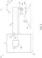
- Fig. 3 is a schematic illustration of examples of robot 10 that may perform methods 300, according to the present disclosure.
- robot 10 includes an end effector 20, an imaging device 30, and a controller 40.
- End effector 20 includes an operation device 70, which may be configured to perform a plurality of operations within a region of a part 100.
- Imaging device 30 may be configured to collect a spatial representation of part 100.
- Controller 40 may be configured to control the operation of at least one component of the robot according to methods 300, which are discussed in more detail herein. This may include controlling the operation of robot 10, of end effector 20, and/or of imaging device 30, such as via one or more control signals 42.
- robot 10 may include an actuator 50 and/or end effector 20 may include an actuator 60.
- Actuator 50 of robot 10 when present, may be configured to move, to operatively translate, and/or to operatively rotate robot 10 relative to part 100, such as during methods 300.
- actuator 60 of end effector 20, when present, may be configured to move, to operatively translate, and/or to rotate at least a subset of end effector 20, such as imaging device 30 and/or operation device 70, relative to part 100.
- Actuators 50/60 may, for example, be configured to operatively translate corresponding structures along the X, Y, and/or Z-axes of Fig. 3 and/or to rotate the corresponding structures about the X, Y, and/or Z-axes.
- Examples of actuators 50/60 include any suitable linear actuator, rotary actuator, mechanical actuator, electric actuator, pneumatic actuator, and/or hydraulic actuator.
- operation device 70 may, in some examples, include an inspection device 72.
- inspection device 72 examples of the inspection device are disclosed herein. Additional examples of operation device 70 and/or of inspection device 72 include a transducer, a sensor, a non-destructive tester, a non-contact inspection device, a painting device, a sanding device, an ultrasound transmitter, an ultrasound receiver, an infrared transmitter, an infrared receiver, and/or an optical imagining device.
- Imaging device 30 may be associated with robot 10 in any suitable manner. As an example, and as illustrated in solid lines in Fig. 4 , imaging device 30 may be associated with and/or operatively attached to a main body 12 of robot 10 and/or end effector 20. In a specific example, imaging device 30 may be operatively attached to and/or may form a portion of operation device 70. In another specific example, actuator 60 may be configured to move imaging device 30 with operation device 70. As another example, imaging device 30 may be spaced-apart from a remainder of robot 10 and also from part 100, as illustrated in dash-dot lines in Fig. 4 . Examples of imaging device 30 include a camera, a still camera, a video camera, an infrared imaging device, a laser-based imaging device, a 3-dimensional camera, and/or an acoustic imaging device.
- imaging device 30 may collect one or more spatial representations of part 100 and/or of a region 110 of the part.
- Robot 10 and/or controller 40 thereof then may utilize the one or more spatial representations of part 100 to conform a predetermined raster scan pattern for movement of end effector 20 to the spatial representation of the part.
- Robot 10 and/or controller 40 additionally or alternatively may define a plurality of normality vectors 120 for the part. The plurality of normality vectors may be based, at least in part, on the spatial representation of the part.
- Robot 10 then may perform a plurality of operations on the part utilizing operation device 70. The operations may be performed such that operation device 70 faces along a corresponding normality vector 120 at each location where an operation is performed.
- Controller 40 may include and/or be any suitable structure, device, and/or devices that may be adapted, configured, designed, constructed, and/or programmed to perform the functions discussed herein.
- controller 40 may include one or more of an electronic controller, a dedicated controller, a special-purpose controller, a personal computer, a special-purpose computer, a display device, a logic device, a memory device, and/or a memory device having computer-readable storage media 44.
- the computer-readable storage media when present, also may be referred to herein as non-transitory computer readable storage media.
- This non-transitory computer readable storage media may include, define, house, and/or store computer-executable instructions, programs, and/or code; and these computer-executable instructions may direct robot 10 and/or controller 40 thereof to perform any suitable portion, or subset, of methods 300. Examples of such non-transitory computer-readable storage media include CD-ROMs, disks, hard drives, flash memory, etc.
- storage, or memory, devices and/or media having computer-executable instructions, as well as computer-implemented methods and other methods according to the present disclosure are considered to be within the scope of subject matter deemed patentable in accordance with Section 101 of Title 35 of the United States Code.
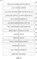
- Fig. 4 is flowchart depicting examples of methods 300 of performing a plurality of operations within a region of a part utilizing an end effector of a robot, according to the present disclosure.
- Figs. 5-12 illustrate various process steps that may be performed by robots 10 and/or during methods 300, according to the present disclosure.
- Methods 300 may include defining a predetermined raster scan pattern at 305, defining operation locations at 310, and/or overlapping a part and the predetermined raster scan pattern at 315.
- Methods 300 also may include positioning the part within a field-of-view of an imaging device at 320 and include collecting a spatial representation of the part at 325.
- Methods 300 further include aligning the predetermined raster scan pattern at 330, may include adjusting the predetermined raster scan pattern at 335, and include defining a plurality of normality vectors at 340 and moving an end effector at 345. Methods 300 also include orienting the end effector at 350 and executing a corresponding operation at 355 and may include triggering an inspection device at 360, displaying displayed information at 365, and/or identifying a part characteristic at 370.
- Defining the predetermined raster scan pattern at 305 may include defining any suitable predetermined raster scan pattern along which the end effector will be moved during the moving at 345.
- the defining at 305 may include defining the predetermined raster scan pattern without, or independent from, any dimensional information of the part.
- the defining at 305 may include defining the predetermined raster scan pattern without prior knowledge of the part and/or without prior knowledge of the part's dimensions. Such a configuration may be beneficial, for example, when methods 300 are performed on older parts, such as older aircraft, for which detailed dimensional information may not readily be available.
- the defining at 305 may include defining the predetermined raster scan pattern based on rough measurements of the part and/or rough measurements of a desired size for the region of the part within which methods 300 will be performed.
- the defining at 305 may include defining the predetermined raster scan patter based, at least in part, or based solely, upon a length of the region of the part, a width of the region of the part, a length of the part, a width of the part, one or more internal dimensions of the part, and/or one or more external dimensions of the part.
- the defining at 305 may include defining the predetermined raster scan pattern based, at least in part, on the detailed dimensional information for the part.
- the predetermined raster scan pattern may include and/or may be defined by a plurality of point-to-point moves that progress, in a raster scan pattern, among a plurality of points 204.
- the defining at 305 may be performed with any suitable timing and/or sequence during methods 300. As examples, the defining at 305 may be performed prior to the defining at 310, prior to the overlapping at 315, prior to the positioning at 320, prior to the collecting at 325, prior to the aligning at 330, and/or prior to the adjusting at 335.
- Defining operation locations at 310 may include defining a plurality of predetermined operation locations at which the plurality of operations will be performed by the end effector and/or during the executing at 355. In some examples, the defining at 310 may include defining the plurality of predetermined operation locations independent from any dimensional information of the part. In some examples, the defining at 310 may include defining the plurality of predetermined operation locations without, or independent from, any dimensional information of the part. Stated another way, the defining at 310 may include defining the plurality of predetermined operation locations without prior knowledge of the part and/or without prior knowledge of the part's dimensions. Similar to the defining at 305, such a configuration may be beneficial, for example, when methods 300 are performed on older parts, such as older aircraft, for which detailed dimensional information may not readily be available.
- the defining at 310 may include defining the plurality of predetermined operation locations based on rough measurements of the part and/or rough measurements of a desired size for the region of the part within which methods 300 will be performed. As more specific examples, the defining at 310 may include defining the plurality of predetermined operation locations based, at least in part, or based solely, upon a length of the region of the part, a width of the region of the part, a length of the part, a width of the part, one or more internal dimensions of the part, and/or one or more external dimensions of the part. When the detailed dimensional information for the part readily may be available, the defining at 310 may include defining the plurality of predetermined operation locations based, at least in part, on the detailed dimensional information for the part.
- the plurality of predetermined operation locations may include and/or may be a subset of points 204 that define the plurality of point-to-point moves of predetermined raster scan pattern 200.
- the defining at 310 may be performed with any suitable timing and/or sequence during methods 300. As examples, the defining at 310 may be performed prior to the defining at 305, prior to the overlapping at 315, prior to the positioning at 320, prior to the collecting at 325, prior to the aligning at 330, and/or prior to the adjusting at 335.
- the predetermined raster scan pattern may be configured to be performed and/or carried out within a defined region in space and/or may be configured to be performed and/or carried out based upon one or more predetermined reference locations. Additionally or alternatively, the predetermined raster scan pattern may be configured to be performed and/or carried out in a predetermined direction relative to a current, or a given, location of the robot. In some such examples, methods 300 further may include overlapping the part and the predetermined raster scan pattern at 315. In some examples, the overlapping at 315 may include positioning the part such that the part is within the predetermined raster scan pattern. In some examples, the overlapping at 315 may include positioning the robot and/or the end effector such that the part is within the predetermined raster scan pattern.
- the overlapping at 315 may be performed with any suitable timing and/or sequence during methods 300. As examples, the overlapping at 315 may be performed subsequent to the defining at 305, subsequent to the defining at 310, prior to the positioning at 320, subsequent to the positioning at 320, responsive to the positioning at 320, prior to the collecting at 325, prior to the aligning at 330, and/or prior to the adjusting at 335.
- Positioning the part within the field-of-view of an imaging device at 320 may include moving the part, the end effector, the imaging device, and/or the robot in any suitable manner to position the part and the imaging device such that the part is in the field-of-view of the imaging device.
- the predetermined raster scan pattern may extend within the field-of-view of the imaging device.
- the positioning at 320 may be responsive to and/or a result of the overlapping at 315.
- the positioning at 320 may be performed with any suitable timing and/or sequence during methods 300. As examples, the positioning at 320 may be performed subsequent to the defining at 305, subsequent to the defining at 310, prior to the overlapping at 315, subsequent to the overlapping at 315, prior to the collecting at 325, prior to the aligning at 330, and/or prior to the adjusting at 335.
- Collecting the spatial representation of the part at 325 may include collecting any suitable spatial representation of the part and may be performed with, via, and/or utilizing the imaging device.
- the spatial representation of the part may include and/or be an image of the part.
- Examples of the image of the part include an optical image of the part and/or an acoustic image of the part.
- a spatial representation that may be collected during the collecting at 325 is schematically illustrated in Fig. 7 and indicated at 102.
- the spatial representation may include spatial information regarding the part, or a surface of the part, in three dimensions.
- the collecting at 325 may be performed with any suitable timing and/or sequence during methods 300. As examples, the collecting at 325 may be performed subsequent to the defining at 305, subsequent to the defining at 310, subsequent to the overlapping at 315, subsequent to the positioning at 320, prior to the aligning at 330, prior to the adjusting at 335, prior to the defining at 340, prior to the moving at 345, prior to the orienting at 350, prior to the executing at 355, prior to the displaying at 365, and/or prior to the identifying at 370.
- Aligning the predetermined raster scan pattern at 330 may include aligning the predetermined raster scan pattern, which describes movement of the end effector relative to the part, with the spatial representation of the part.
- the aligning at 330 may be accomplished in any suitable manner.
- the aligning at 330 may include physically orienting the robot, and the part, relative to one another and/or such that the predetermined raster scan pattern extends within and/or encompasses the region of the part.
- the aligning at 330 may include utilizing an actuator of the robot, such as actuator 50 of Fig. 3 , and/or an actuator of the end effector, such as actuator 60 of Fig. 3 , to align the predetermined raster scan pattern with the spatial representation of the part.
- the aligning at 330 may include moving, translating, and/or rotating at least a portion of the robot relative to the part, moving, translating, and/or rotating at least a portion of the part relative to the robot, and/or adjusting a reference point of the predetermined raster scan pattern, such as a start location 206 for the predetermined raster scan pattern and/or an end location 208 for the predetermined raster scan pattern, which are illustrated in Fig. 8 , such that the predetermined raster scan pattern encompasses the region of the part.
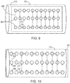
- the aligning at 330 is illustrated by the transition from Fig. 8 to Fig. 9 .
- predetermined raster scan pattern 200 and/or points 204 thereof may not be aligned with spatial representation 102.
- points 204, or all points 204 may not be positioned on and/or within spatial representation 102, which may represent region 110 of the part.
- predetermined raster scan pattern 200 and/or points 204 thereof may be aligned with spatial representation 102 and/or may extend within region 110.
- the aligning at 330 may be performed with any suitable timing and/or sequence during methods 300.
- the aligning at 330 may be performed subsequent to the defining at 305, subsequent to the defining at 310, subsequent to the overlapping at 315, subsequent to the positioning at 320, subsequent to the collecting at 325, subsequent to the adjusting at 335, concurrently with the adjusting at 335, responsive to the adjusting at 335, as a result of the adjusting at 335, prior to the adjusting at 335, prior to the defining at 340, prior to the moving at 345, prior to the orienting at 350, prior to the executing at 355, prior to the displaying at 365, and/or prior to the identifying at 370.
- Adjusting the predetermined raster scan pattern at 335 may include adjusting the predetermined raster scan pattern to produce and/or generate an adjusted raster scan pattern 202 that may be based, at least in part, on the spatial representation of the part that was collected during the collecting at 325. Stated another way, the adjusting at 335 may include adjusting the predetermined raster scan pattern such that the predetermined raster scan pattern conforms to the spatial representation of the part. Stated yet another way, the adjusting at 335 may include adjusting the predetermined raster scan pattern such that the adjusted raster scan pattern extends entirely within the region of the part where the plurality of operations are to be performed.
- the adjusting at 335 may include adjusting the predetermined raster scan pattern such that the predetermined raster scan pattern is representative of, or extends within a representative region of, the spatial representation of the part.
- the moving at 345 may include moving the end effector relative to the part along the adjusted raster scan pattern.
- the adjusting at 335 may include adjusting the predetermined raster scan pattern in any suitable manner.
- the adjusting at 335 may include scaling at least one portion and/or region of the predetermined raster scan pattern to produce and/or generate the adjusted raster scan pattern.
- the adjusting at 335 may include truncating and/or shrinking at least one portion and/or region of the predetermined raster scan pattern to produce and/or generate the adjusted raster scan pattern.
- the adjusting at 335 may include extending and/or stretching at least one portion and/or region of the predetermined raster scan pattern to produce and/or generate the adjusted raster scan pattern.
- the adjusting at 335 is illustrated by the transition from Fig. 9 to Fig. 10 .
- predetermined raster scan pattern 200 is smaller than and/or does not conform entirely to region 110 of the part.
- adjusted raster scan pattern 202 is comparable in size to region 110, more fully encompasses region 110, and/or more fully fills region 110.
- the adjusting at 335 includes scaling, or expanding, predetermined raster scan pattern 200 along two axes to generate adjusted raster scan pattern 202.
- a location of points 204 also may be changed and/or adjusted during the adjusting at 335 such that adjusted raster scan pattern 202 still is defined by a plurality of point-to-point moves among points 204.
- the adjusting at 335 also may be referred to herein as adjusting the plurality of points 204 and/or as adjusting the plurality of predetermined operation locations 210, such as to produce and/or generated an adjusted plurality of predetermined operation locations 212.
- the defining at 340 may include defining the plurality of normality vectors at each adjusted operation location of the adjusted plurality of operation locations. Additionally or alternatively, the orienting at 350 may include orienting the end effector such that the operation device faces toward each adjusted operation location along a corresponding normality vector of the plurality of normality vectors.
- the adjusting at 335 may be performed with any suitable timing and/or sequence during methods 300. As examples, the adjusting at 335 may be performed subsequent to the defining at 305, subsequent to the defining at 310, subsequent to the overlapping at 315, subsequent to the positioning at 320, subsequent to the collecting at 325, subsequent to the aligning at 330, prior to the defining at340, prior to the moving at 345, prior to the orienting at 350, prior to the executing at 355, prior to the displaying at 365, and/or prior to the identifying at 370.
- Defining the plurality of normality vectors at 340 may include defining the plurality of normality vectors for the part and/or at the plurality of predetermined operation locations.
- the defining at 340 may be based, at least in part, on the spatial representation of the part that was collected during the collecting at 325.
- each operation location may be defined along the predetermined raster scan pattern and/or may be a selected point of a plurality of points that define the predetermined raster scan pattern.
- the defining at 340 may be accomplished in any suitable manner.
- the defining at 340 may include quantifying a surface curvature of the part at each operation location.
- the quantifying the surface curvature may include fitting a surface to the spatial representation of the part at each operation location.
- the defining at 340 may include calculating the surface normal vector based, at least in part, on the surface curvature and/or the fitted surface at each operation location.
- the defining at 340 may include calculating a surface normal direction at each operation location.
- the defining at 340 may be performed utilizing a controller of the robot, such as controller 40 of Fig. 3 , and/or utilizing a computing device that is in communication with the robot.
- Figs. 3 and 12 illustrate a side view of normality vectors 120 at points 204 and/or predetermined operation locations 210
- Fig. 11 illustrates a top view of normality vectors 120 (illustrated as X's).
- the defining at 340 may be performed with any suitable timing and/or sequence during methods 300. As examples, the defining at 340 may be performed subsequent to the defining at 305, subsequent to the defining at 310, subsequent to the overlapping at 315, subsequent to the positioning at 320, subsequent to the collecting at 325, subsequent to the aligning at 330, subsequent to the adjusting at 335, prior to the moving at 345, prior to the orienting at 350, prior to the executing at 355, prior to the displaying at 365, and/or prior to the identifying at 370.
- Moving the end effector at 345 may include moving the end effector relative to the part and/or along the predetermined raster scan pattern.
- the moving at 345 may include performing a plurality of point-to-point moves with the end effector and/or along the predetermined raster scan pattern.
- a length of each point-to-point move may be relatively small.
- the length of each point-to-point move may be at least 0.1 millimeter (mm), at least 0.2 mm, at least 0.4 mm, at least 0.6 mm, at least 0.8 mm, at least 1 mm, at least 1.2 mm, at least 1.4 mm, at least 1.6 mm, at least 1.8 mm, at least 2 mm, at least 2.2 mm, at least 2.4 mm, at least 2.6 mm, at least 2.8 mm, at least 3 mm, at least 4 mm, at least 5 mm, at least 6 mm, at least 8 mm, at least 10 mm, at least 15 mm, at least 20 mm, at least 25 mm, at most 100 mm, at most 90 mm, at most 80 mm, at most 70 mm, at most 60 mm, at most 50 mm, at most 40 mm, at most 30 mm, at most 25 mm, at most 20 mm, at most 15 mm, at most 10 mm, at most 5 mm, and/
- the short distance between successive point-to-point moves may permit and/or facilitate improved measurement resolution.
- the short distance between successive point-to-point moves may permit and/or facilitate more uniform modification to the part, may provide a greater number of options regarding where, on the part, the modifications may be performed, and/or may provide a greater number of options regarding spacing between adjacent modifications.
- the moving at 345 is illustrated in Fig. 11 by the arrows illustrating the path taken for predetermined raster scan pattern 200.
- the moving at 345 also is illustrated in Fig. 12 by the transition from the configuration illustrated in solid lines to the configuration illustrated in dashed lines to the configuration illustrated in dotted lines, with the progression of these configurations occurring along predetermined raster scan pattern 200.
- the moving at 345 may be accomplished in any suitable manner.
- the moving at 345 may be accomplished with, via, and/or utilizing an actuator of the robot and/or an actuator of the end effector, examples of which are disclosed herein.
- the moving at 345 may include continuously, or at least substantially continuously, moving the end effector along the predetermined raster scan pattern, at least until the end effector traverses an entirety of the predetermined raster scan pattern. Stated another way, and subsequent to initiating the moving at 345, methods 300 may include continuously, or at least substantially continuously moving the end effector along the predetermined raster scan pattern until the end effector has moved along the entire raster scan pattern.
- the moving at 345 may include intermittently moving the end effector along the predetermined raster scan pattern.
- the moving at 345 may include moving the end effector along the predetermined raster scan pattern until the end effector reaches a given operation location of the plurality of operation locations. Upon reaching the given operation location, the end effector may stop at the given operation location, such as to permit the end effector to perform the corresponding operation at the given operation location.
- the moving at 345 may be performed with any suitable timing and/or sequence during methods 300.
- the moving at 345 may be performed subsequent to the defining at 305, subsequent to the defining at 310, subsequent to the overlapping at 315, subsequent to the positioning at 320, subsequent to the collecting at 325, subsequent to the aligning at 330, subsequent to the adjusting at 335, subsequent to the defining at 340, prior to the orienting at 350, during the orienting at 350, at least partially concurrently with the orienting at 350, prior to the executing at 355, prior to the displaying at 365, and/or prior to the identifying at 370.
- Orienting the end effector at 350 may be performed at each operation location of the plurality of predetermined operation locations and/or along the predetermined raster scan pattern.
- the orienting at 350 may include orienting the end effector such that the operation device of the end effector faces toward each operation location along a corresponding normality vector of the plurality of normality vectors.
- the orienting at 350 includes aligning the operation device along the corresponding normality vector at each operation location. As discussed in more detail herein, such a configuration may improve an efficiency of, an effectiveness of, a reproducibility of, and/or a uniformity of the corresponding operation that is performed at each operation location.
- the orienting at 350 may be performed in any suitable manner.
- the orienting at 350 may include operatively translating the operation device, such as relative to the part, in at least one, at least two, or three orthogonal directions.
- the orienting at 350 may include operatively rotating the operating device, such as relative to the part, about at least one, at least two, or three orthogonal axes.
- the orienting at 350 may include establishing a predetermined device-to-part distance between the operation device and the part.
- the establishing the predetermined device-to-part distance may include establishing a spaced-apart relationship between the operation device and the part.
- the predetermined device-to-part distance may be constant, or at least substantially constant, at each operation location.
- a first predetermined device-to-part distance associated with a first operation location of the plurality of operation locations may differ from a second predetermined device-to-part distance associated with a second operation location of the plurality of operation locations.
- the orienting at 350 may be accomplished in any suitable manner. As examples, the orienting at 350 may be performed utilizing the actuator of the robot and/or utilizing the actuator of the end effector.
- Fig. 12 The orienting at 350 is illustrated in Fig. 12 .
- operation device 70 is oriented, relative to part 100, such that the operation device faces toward the part along a corresponding normality vector 120.
- Fig. 12 also illustrates a configuration in which the predetermined device-to-part distance is constant, or at least substantially constant, at each predetermined operation location 210.
- the orienting at 350 may be performed with any suitable timing and/or sequence during methods 300.
- the orienting at 350 may be performed subsequent to the defining at 305, subsequent to the defining at 310, subsequent to the overlapping at 315, subsequent to the positioning at 320, subsequent to the collecting at 325, subsequent to the aligning at 330, subsequent to the adjusting at 335, subsequent to the defining at 340, subsequent to the moving at 345, during the moving at 345, at least partially concurrently with the moving at 345, prior to the executing at 355, prior to the displaying at 365, and/or prior to the identifying at 370.
- Executing the corresponding operation at 355 may be performed at each operation location of the plurality of predetermined operation locations and/or along the predetermined raster scan pattern.
- the executing at 355 may include executing a corresponding operation of the plurality of operations with, via, and/or utilizing the operation device.
- the plurality of operations may include and/or be any suitable operation that may be performed on the part and/or by the operation device.
- the plurality of operations may include a plurality of measurements of the part. In such examples, the measurements of the part and/or a reproducibility of the measurements of the part may be improved by the orienting at 350.
- Examples of the plurality of measurements of the part include evaluating the part, performing a non-destructive test on the part, performing a non-contact inspection of the part, performing an ultrasound evaluation of the part, performing an infrared evaluation of the part, and/or performing an optical evaluation of the part.
- the plurality of operations may include a plurality of modifications to the part.
- the modifications to the part, a reproducibility of the modifications to the part, and/or a uniformity of the modifications to the part may be improved by the orienting at 350.
- Examples of the plurality of modifications to the part include painting the part, sanding the part, machining the part, and/or drilling holes in the part.
- the executing at 355 may include performing an ultrasound inspection of the part, such as at each operation location.
- the operation device may include and/or be an ultrasound device.
- the executing at 355 may include initiating an ultrasonic vibration in the part at each operation location and detecting an emitted ultrasonic vibration emitted from the part at each operation location. The initiating may be performed in any suitable manner, such as utilizing any suitable laser ultrasound device and/or mechanical actuator.
- the initiating the ultrasonic vibration may include initiating with a laser of the operation device.
- the orienting at 350 may include positioning a focal point of the laser within each operation location and/or directing the laser incident upon the part along the corresponding normality vector.
- the detecting the emitted ultrasonic vibration may include detecting with an ultrasonic detector.
- the orienting at 350 may include positioning the ultrasonic detector along the corresponding normality vector and/or positioning the ultrasonic detector such that the emitted ultrasonic vibration is incident upon the ultrasonic detector from the corresponding normality direction.
- the plurality of operation locations may include any suitable portion, fraction, and/or subset of the plurality of points that defines the plurality of point-to-point moves of the predetermined raster scan pattern.
- Examples of the subset of the plurality of points include at least 1%, at least 5%, at least 10%, at least 20%, at least 30%, at least 40%, at least 50%, at least 60%, at least 70%, at least 80%, at least 90%, at least 95%, at least 99%, 100%, at most 100%, at most 90%, at most 80%, at most 70%, at most 60%, at most 50%, at most 40%, at most 30%, at most 20%, and/or at most 10% of the plurality of points.
- Triggering the inspection device at 360 may include triggering any suitable inspection device, examples of which are disclosed herein.
- the triggering at 360 may include generating a trigger event, such as may indicate that the event device is at a corresponding predetermined operation location and/or that the event device is oriented along the corresponding normality vector.
- the triggering at 360 also may include providing the trigger event to the inspection device, such as to indicate to the inspection device that an inspection is to be performed.
- the triggering at 360 also may include performing an inspection with the inspection device, such as responsive to receipt of the trigger event.
- the triggering at 360 may include triggering with, via, and/or utilizing any suitable trigger methodology and/or algorithm. This may include any suitable predetermined trigger algorithm, which may be utilized to establish and/or determine the plurality of operation locations.
- the adjusting at 335 further may include adjusting the predetermined trigger algorithm.
- the predetermined trigger algorithm may indicate a fixed number of trigger events.
- the adjusting may include scaling a location of the trigger events in a manner that may be similar to the scaling of the predetermined raster scan pattern.
- the predetermined trigger algorithm may indicate a fixed distance between trigger events.
- the adjusting may include increasing a number of trigger events performed along a given axis responsive to an increase in a size of the predetermined raster scan pattern along the given axis and/or decreasing the number of trigger events performed along the give axis responsive to a decrease in the size of the predetermined raster scan pattern along the given axis.
- Displaying displayed information at 365 may include displaying any suitable information, such as to an operator of the robot, that may be obtained via methods 300 and/or that may be produced as a result of methods 300.
- the displaying at 365 may include displaying displayed information that may be based, at least in part, on the emitted ultrasonic vibration emitted from the part at each operation location. Examples of such displayed information include an A-scan at a location on the part, a B-scan along a line on the part, a C-scan of an area the part, and/or a three dimensional or Voxel-based ultrasonic display, image, or volumetric image of the part.
- Identifying the part characteristic at 370 may include identifying any suitable part characteristic based, at least in part, on the displaying at 365.
- the identifying at 370 may include identifying a defect in the part, damage to the part, degradation of the part, a physical dimension of the part, and/or a coating thickness of a coating that coats the part.
- the terms “adapted” and “configured” mean that the element, component, or other subject matter is designed and/or intended to perform a given function. Thus, the use of the terms “adapted” and “configured” should not be construed to mean that a given element, component, or other subject matter is simply “capable of” performing a given function but that the element, component, and/or other subject matter is specifically selected, created, implemented, utilized, programmed, and/or designed for the purpose of performing the function. It is also within the scope of the present disclosure that elements, components, and/or other recited subject matter that is recited as being adapted to perform a particular function may additionally or alternatively be described as being configured to perform that function, and vice versa. Similarly, subject matter that is recited as being configured to perform a particular function may additionally or alternatively be described as being operative to perform that function.
- the phrase "at least one,” in reference to a list of one or more entities should be understood to mean at least one entity selected from any one or more of the entities in the list of entities, but not necessarily including at least one of each and every entity specifically listed within the list of entities and not excluding any combinations of entities in the list of entities.
- This definition also allows that entities may optionally be present other than the entities specifically identified within the list of entities to which the phrase "at least one" refers, whether related or unrelated to those entities specifically identified.
- At least one of A and B may refer, in one embodiment, to at least one, optionally including more than one, A, with no B present (and optionally including entities other than B); in another embodiment, to at least one, optionally including more than one, B, with no A present (and optionally including entities other than A); in yet another embodiment, to at least one, optionally including more than one, A, and at least one, optionally including more than one, B (and optionally including other entities).
- each of the expressions “at least one of A, B, and C,” “at least one of A, B, or C,” “one or more of A, B, and C,” “one or more of A, B, or C” and “A, B, and/or C” may mean A alone, B alone, C alone, A and B together, A and C together, B and C together, A, B, and C together, and optionally any of the above in combination with at least one other entity.
- the phrase, "for example,” the phrase, “as an example,” and/or simply the term “example,” when used with reference to one or more components, features, details, structures, embodiments, and/or methods according to the present disclosure, are intended to convey that the described component, feature, detail, structure, embodiment, and/or method is an illustrative, non-exclusive example of components, features, details, structures, embodiments, and/or methods according to the present disclosure.
- an object that is at least substantially formed from a material includes objects for which at least 75% of the objects are formed from the material and also includes objects that are completely formed from the material.
- a first length that is at least substantially as long as a second length includes first lengths that are within 75% of the second length and also includes first lengths that are as long as the second length.
Landscapes
- Engineering & Computer Science (AREA)
- Physics & Mathematics (AREA)
- General Physics & Mathematics (AREA)
- Mechanical Engineering (AREA)
- Robotics (AREA)
- General Health & Medical Sciences (AREA)
- Health & Medical Sciences (AREA)
- Pathology (AREA)
- Life Sciences & Earth Sciences (AREA)
- Chemical & Material Sciences (AREA)
- Analytical Chemistry (AREA)
- Biochemistry (AREA)
- Immunology (AREA)
- Manufacturing & Machinery (AREA)
- Theoretical Computer Science (AREA)
- Computer Vision & Pattern Recognition (AREA)
- Automation & Control Theory (AREA)
- Human Computer Interaction (AREA)
- Software Systems (AREA)
- Aviation & Aerospace Engineering (AREA)
- Transportation (AREA)
- Acoustics & Sound (AREA)
- Medical Informatics (AREA)
- Data Mining & Analysis (AREA)
- Evolutionary Computation (AREA)
- Signal Processing (AREA)
- Artificial Intelligence (AREA)
- Computing Systems (AREA)
- General Engineering & Computer Science (AREA)
- Mathematical Physics (AREA)
- Orthopedic Medicine & Surgery (AREA)
- Quality & Reliability (AREA)
- Optics & Photonics (AREA)
- Manipulator (AREA)
Abstract
Description
- The present disclosure relates generally to methods of performing a plurality of operations within a region of a part utilizing an end effector of a robot and/or to robots that perform the methods.
- Robots may be utilized to perform a variety of different operations with and/or on a part. As an example, robots may be utilized to assemble one or more components of an aircraft. Historically, robots are effective at performing operations on a part with a well-defined, and quantitatively known, geometry. In such examples, numeric descriptions of the part may be provided to the robot, and the robot may utilize this information to control motion of the robot, locations at which the operations are performed, and the like. Utilizing a robot on parts, or in environments, that are not well-defined and quantitatively known presents unique operational challenges and may increase costs substantially. As an example, it may be necessary to manually train the robot to navigate to various locations on the part and/or to perform desired operations at the various locations. Thus, there exists a need for improved methods of performing a plurality of operations within a region of a part utilizing an end effector of a robot and/or for robots that perform the methods.
- Methods of performing a plurality of operations within a region of a part utilizing an end effector of a robot and robots that perform the methods are disclosed herein. The methods include collecting a spatial representation of the part. The collecting may include collecting with an imaging device that may be associated with the robot. The methods also include aligning a predetermined raster scan pattern for movement of the end effector relative to the part with the spatial representation of the part. The methods further include defining a plurality of normality vectors for the part at a plurality of predetermined operation locations for operation of the end effector. The defining may be based, at least in part, on the spatial representation of the part, and each operation location may be defined along the predetermined raster scan pattern. The methods also include moving the end effector relative to the part and along the predetermined raster scan pattern. The methods further include orienting the end effector such that an operation device of the end effector faces toward each operation location along a corresponding normality vector. The methods also include executing a corresponding operation of the plurality of operations with the operation device and at each operation location.
-
-
Fig. 1 is a schematic illustration of an example of an aircraft that may be utilized with the robots and methods according to the present disclosure. -
Fig. 2 is a schematic illustration of an example of a wing of an aircraft that may be utilized with the robots and methods according to the present disclosure. -
Fig. 3 is a schematic illustration of examples of a robot that may perform methods, according to the present disclosure. -
Fig. 4 is flowchart depicting examples of methods of performing a plurality of operations within a region of a part utilizing an end effector of a robot, according to the present disclosure. -
Fig. 5 is a schematic illustration of an example of a predetermined raster scan patter according to the present disclosure. -
Fig. 6 is a schematic illustration of examples of a plurality of predetermined event locations within a predetermined raster scan patter, according to the present disclosure. -
Fig. 7 is a schematic illustration of an example of a spatial representation of a part that may be utilized with the robots and methods according to the present disclosure. -
Fig. 8 is a schematic illustration an example of an initial orientation between a predetermined raster scan pattern and a spatial representation of a part, according to the present disclosure. -
Fig. 9 illustrates an example of alignment between the predetermined raster scan pattern ofFig. 8 and the spatial representation of the part ofFig. 8 . -
Fig. 10 is a schematic illustration of an example of an adjusted raster scan pattern, according to the present disclosure. -
Fig. 11 is a schematic illustration of an example of a plurality of normality vectors, according to the present disclosure. -
Fig. 12 is a schematic illustration of examples of motion of an end effector of a robot relative to a part while performing methods, according to the present disclosure. -
Figs. 1-12 provide illustrative, non-exclusive examples ofrobots 10 that includeend effectors 20 and/or ofmethods 300, according to the present disclosure. Elements that serve a similar, or at least substantially similar, purpose are labeled with like numbers in each ofFigs. 1-12 , and these elements may not be discussed in detail herein with reference to each ofFigs. 1-12 . Similarly, all elements may not be labeled in each ofFigs. 1-12 , but reference numerals associated therewith may be utilized herein for consistency. Elements, components, and/or features that are discussed herein with reference to one or more ofFigs. 1-12 may be included in and/or utilized with any ofFigs. 1-12 without departing from the scope of the present disclosure. - In general, elements that are likely to be included in a given (i.e., a particular) embodiment are illustrated in solid lines, while elements that are optional to a given embodiment are illustrated in dashed lines. However, elements that are shown in solid lines are not essential to all embodiments, and an element shown in solid lines may be omitted from a particular embodiment without departing from the scope of the present disclosure.
-
Fig. 1 is a schematic illustration of an example of anaircraft 700 that may be utilized with the robots (such asrobot 10 as shown inFig. 3 ) and/or methods (such asmethods 300 as shown inFig. 3 ) according to the present disclosure; andFig. 2 is a schematic illustration of an example of awing 740 of anaircraft 700 that may be utilized with the robots and methods according to the present disclosure. As illustrated inFig. 1 ,aircraft 700 may include anairframe 710 that includes afuselage 720, which may be formed from a plurality offuselage barrel segments 730. As also illustrated inFig. 1 ,aircraft 700 may includewings 740 and astabilizer 750.Aircraft 700 further may include a plurality ofskin segments 790, which may be supported by a plurality ofstringers 770 and/orframes 780. - Turning to
Fig. 2 ,wings 740 may include a plurality ofwing stringers 742 and/or a plurality of ribs, or spars, 744, which may form and/or define aninner support structure 746 thereof.Wings 740 also may includeskin segments 790, and aninner surface 748 ofskin segments 790 may be attached to and/or supported byinner support structure 746. - During assembly, testing, and/or inspection of
aircraft 700, it may be desirable to utilize a robot, such asrobots 10, which are discussed in more detail herein, to perform one or more operations on the aircraft. As discussed, conventional robots have required detailed numeric descriptions, such as computer aided drawings, of the aircraft in order to perform such operations and/or have relied upon time-consuming teaching operations to teach the robot how to perform the operations. While effective, such conventional robots also have been costly to implement. In contrast to conventional robots, and as discussed in more detail herein,robots 10 and/ormethods 300, according to the present disclosure, may be utilized to perform the one or more operations on the aircraft, or on another part, without the need for such detailed numeric descriptions and/or teaching operations, thereby improving the efficiency of the operations. -
Fig. 3 is a schematic illustration of examples ofrobot 10 that may performmethods 300, according to the present disclosure. As illustrated in solid lines inFig. 3 ,robot 10 includes anend effector 20, animaging device 30, and acontroller 40.End effector 20 includes anoperation device 70, which may be configured to perform a plurality of operations within a region of apart 100.Imaging device 30 may be configured to collect a spatial representation ofpart 100.Controller 40 may be configured to control the operation of at least one component of the robot according tomethods 300, which are discussed in more detail herein. This may include controlling the operation ofrobot 10, ofend effector 20, and/or ofimaging device 30, such as via one ormore control signals 42. - As illustrated in dashed lines in
Fig. 3 ,robot 10 may include anactuator 50 and/orend effector 20 may include anactuator 60.Actuator 50 ofrobot 10, when present, may be configured to move, to operatively translate, and/or to operatively rotaterobot 10 relative topart 100, such as duringmethods 300. Similarly,actuator 60 ofend effector 20, when present, may be configured to move, to operatively translate, and/or to rotate at least a subset ofend effector 20, such asimaging device 30 and/oroperation device 70, relative topart 100.Actuators 50/60 may, for example, be configured to operatively translate corresponding structures along the X, Y, and/or Z-axes ofFig. 3 and/or to rotate the corresponding structures about the X, Y, and/or Z-axes. Examples ofactuators 50/60 include any suitable linear actuator, rotary actuator, mechanical actuator, electric actuator, pneumatic actuator, and/or hydraulic actuator. - As illustrated in dashed lines in
Fig. 3 ,operation device 70 may, in some examples, include aninspection device 72. Examples of the inspection device are disclosed herein. Additional examples ofoperation device 70 and/or ofinspection device 72 include a transducer, a sensor, a non-destructive tester, a non-contact inspection device, a painting device, a sanding device, an ultrasound transmitter, an ultrasound receiver, an infrared transmitter, an infrared receiver, and/or an optical imagining device. -
Imaging device 30 may be associated withrobot 10 in any suitable manner. As an example, and as illustrated in solid lines inFig. 4 ,imaging device 30 may be associated with and/or operatively attached to amain body 12 ofrobot 10 and/orend effector 20. In a specific example,imaging device 30 may be operatively attached to and/or may form a portion ofoperation device 70. In another specific example,actuator 60 may be configured to moveimaging device 30 withoperation device 70. As another example,imaging device 30 may be spaced-apart from a remainder ofrobot 10 and also frompart 100, as illustrated in dash-dot lines inFig. 4 . Examples ofimaging device 30 include a camera, a still camera, a video camera, an infrared imaging device, a laser-based imaging device, a 3-dimensional camera, and/or an acoustic imaging device. - During operation of
robots 10, and as discussed in more detail herein with reference tomethods 300,imaging device 30 may collect one or more spatial representations ofpart 100 and/or of aregion 110 of the part.Robot 10 and/orcontroller 40 thereof then may utilize the one or more spatial representations ofpart 100 to conform a predetermined raster scan pattern for movement ofend effector 20 to the spatial representation of the part.Robot 10 and/orcontroller 40 additionally or alternatively may define a plurality ofnormality vectors 120 for the part. The plurality of normality vectors may be based, at least in part, on the spatial representation of the part.Robot 10 then may perform a plurality of operations on the part utilizingoperation device 70. The operations may be performed such thatoperation device 70 faces along a correspondingnormality vector 120 at each location where an operation is performed. -
Controller 40 may include and/or be any suitable structure, device, and/or devices that may be adapted, configured, designed, constructed, and/or programmed to perform the functions discussed herein. As examples,controller 40 may include one or more of an electronic controller, a dedicated controller, a special-purpose controller, a personal computer, a special-purpose computer, a display device, a logic device, a memory device, and/or a memory device having computer-readable storage media 44. - The computer-readable storage media, when present, also may be referred to herein as non-transitory computer readable storage media. This non-transitory computer readable storage media may include, define, house, and/or store computer-executable instructions, programs, and/or code; and these computer-executable instructions may direct
robot 10 and/orcontroller 40 thereof to perform any suitable portion, or subset, ofmethods 300. Examples of such non-transitory computer-readable storage media include CD-ROMs, disks, hard drives, flash memory, etc. As used herein, storage, or memory, devices and/or media having computer-executable instructions, as well as computer-implemented methods and other methods according to the present disclosure, are considered to be within the scope of subject matter deemed patentable in accordance with Section 101 of Title 35 of the United States Code. -
Fig. 4 is flowchart depicting examples ofmethods 300 of performing a plurality of operations within a region of a part utilizing an end effector of a robot, according to the present disclosure.Figs. 5-12 illustrate various process steps that may be performed byrobots 10 and/or duringmethods 300, according to the present disclosure.Methods 300 may include defining a predetermined raster scan pattern at 305, defining operation locations at 310, and/or overlapping a part and the predetermined raster scan pattern at 315.Methods 300 also may include positioning the part within a field-of-view of an imaging device at 320 and include collecting a spatial representation of the part at 325.Methods 300 further include aligning the predetermined raster scan pattern at 330, may include adjusting the predetermined raster scan pattern at 335, and include defining a plurality of normality vectors at 340 and moving an end effector at 345.Methods 300 also include orienting the end effector at 350 and executing a corresponding operation at 355 and may include triggering an inspection device at 360, displaying displayed information at 365, and/or identifying a part characteristic at 370. - Defining the predetermined raster scan pattern at 305 may include defining any suitable predetermined raster scan pattern along which the end effector will be moved during the moving at 345. In some examples, the defining at 305 may include defining the predetermined raster scan pattern without, or independent from, any dimensional information of the part. Stated another way, the defining at 305 may include defining the predetermined raster scan pattern without prior knowledge of the part and/or without prior knowledge of the part's dimensions. Such a configuration may be beneficial, for example, when
methods 300 are performed on older parts, such as older aircraft, for which detailed dimensional information may not readily be available. - In some examples, the defining at 305 may include defining the predetermined raster scan pattern based on rough measurements of the part and/or rough measurements of a desired size for the region of the part within which
methods 300 will be performed. As more specific examples, the defining at 305 may include defining the predetermined raster scan patter based, at least in part, or based solely, upon a length of the region of the part, a width of the region of the part, a length of the part, a width of the part, one or more internal dimensions of the part, and/or one or more external dimensions of the part. - In some examples, and while not required, detailed dimensional information for the part readily may be available. Examples of such detailed dimensional information include numerical descriptions of the part, such as computer-aided design (CAD) and/or computer-aided manufacturing (CAM) drawings of the part. In such examples, the defining at 305 may include defining the predetermined raster scan pattern based, at least in part, on the detailed dimensional information for the part.
- An example of the predetermined raster scan pattern is illustrated in
Fig. 5 and indicated at 200. As illustrated, the predetermined raster scan pattern may include and/or may be defined by a plurality of point-to-point moves that progress, in a raster scan pattern, among a plurality ofpoints 204. - The defining at 305 may be performed with any suitable timing and/or sequence during
methods 300. As examples, the defining at 305 may be performed prior to the defining at 310, prior to the overlapping at 315, prior to the positioning at 320, prior to the collecting at 325, prior to the aligning at 330, and/or prior to the adjusting at 335. - Defining operation locations at 310 may include defining a plurality of predetermined operation locations at which the plurality of operations will be performed by the end effector and/or during the executing at 355. In some examples, the defining at 310 may include defining the plurality of predetermined operation locations independent from any dimensional information of the part. In some examples, the defining at 310 may include defining the plurality of predetermined operation locations without, or independent from, any dimensional information of the part. Stated another way, the defining at 310 may include defining the plurality of predetermined operation locations without prior knowledge of the part and/or without prior knowledge of the part's dimensions. Similar to the defining at 305, such a configuration may be beneficial, for example, when
methods 300 are performed on older parts, such as older aircraft, for which detailed dimensional information may not readily be available. - In some examples, the defining at 310 may include defining the plurality of predetermined operation locations based on rough measurements of the part and/or rough measurements of a desired size for the region of the part within which
methods 300 will be performed. As more specific examples, the defining at 310 may include defining the plurality of predetermined operation locations based, at least in part, or based solely, upon a length of the region of the part, a width of the region of the part, a length of the part, a width of the part, one or more internal dimensions of the part, and/or one or more external dimensions of the part. When the detailed dimensional information for the part readily may be available, the defining at 310 may include defining the plurality of predetermined operation locations based, at least in part, on the detailed dimensional information for the part. - An example of the plurality of predetermined operation locations is illustrated in
Fig. 6 and indicated at 210. As illustrated, the plurality of predetermined operation locations may include and/or may be a subset ofpoints 204 that define the plurality of point-to-point moves of predeterminedraster scan pattern 200. - The defining at 310 may be performed with any suitable timing and/or sequence during
methods 300. As examples, the defining at 310 may be performed prior to the defining at 305, prior to the overlapping at 315, prior to the positioning at 320, prior to the collecting at 325, prior to the aligning at 330, and/or prior to the adjusting at 335. - In some examples, the predetermined raster scan pattern may be configured to be performed and/or carried out within a defined region in space and/or may be configured to be performed and/or carried out based upon one or more predetermined reference locations. Additionally or alternatively, the predetermined raster scan pattern may be configured to be performed and/or carried out in a predetermined direction relative to a current, or a given, location of the robot. In some such examples,
methods 300 further may include overlapping the part and the predetermined raster scan pattern at 315. In some examples, the overlapping at 315 may include positioning the part such that the part is within the predetermined raster scan pattern. In some examples, the overlapping at 315 may include positioning the robot and/or the end effector such that the part is within the predetermined raster scan pattern. - The overlapping at 315 may be performed with any suitable timing and/or sequence during
methods 300. As examples, the overlapping at 315 may be performed subsequent to the defining at 305, subsequent to the defining at 310, prior to the positioning at 320, subsequent to the positioning at 320, responsive to the positioning at 320, prior to the collecting at 325, prior to the aligning at 330, and/or prior to the adjusting at 335. - Positioning the part within the field-of-view of an imaging device at 320 may include moving the part, the end effector, the imaging device, and/or the robot in any suitable manner to position the part and the imaging device such that the part is in the field-of-view of the imaging device. In some examples, the predetermined raster scan pattern may extend within the field-of-view of the imaging device. In some such examples, the positioning at 320 may be responsive to and/or a result of the overlapping at 315.
- The positioning at 320 may be performed with any suitable timing and/or sequence during
methods 300. As examples, the positioning at 320 may be performed subsequent to the defining at 305, subsequent to the defining at 310, prior to the overlapping at 315, subsequent to the overlapping at 315, prior to the collecting at 325, prior to the aligning at 330, and/or prior to the adjusting at 335. - Collecting the spatial representation of the part at 325 may include collecting any suitable spatial representation of the part and may be performed with, via, and/or utilizing the imaging device. In some examples the spatial representation of the part may include and/or be an image of the part. Examples of the image of the part include an optical image of the part and/or an acoustic image of the part.
- An example of a spatial representation that may be collected during the collecting at 325 is schematically illustrated in
Fig. 7 and indicated at 102. As illustrated, the spatial representation may include spatial information regarding the part, or a surface of the part, in three dimensions. - The collecting at 325 may be performed with any suitable timing and/or sequence during
methods 300. As examples, the collecting at 325 may be performed subsequent to the defining at 305, subsequent to the defining at 310, subsequent to the overlapping at 315, subsequent to the positioning at 320, prior to the aligning at 330, prior to the adjusting at 335, prior to the defining at 340, prior to the moving at 345, prior to the orienting at 350, prior to the executing at 355, prior to the displaying at 365, and/or prior to the identifying at 370. - Aligning the predetermined raster scan pattern at 330 may include aligning the predetermined raster scan pattern, which describes movement of the end effector relative to the part, with the spatial representation of the part. The aligning at 330 may be accomplished in any suitable manner. As an example, the aligning at 330 may include physically orienting the robot, and the part, relative to one another and/or such that the predetermined raster scan pattern extends within and/or encompasses the region of the part. As anther example, the aligning at 330 may include utilizing an actuator of the robot, such as
actuator 50 ofFig. 3 , and/or an actuator of the end effector, such asactuator 60 ofFig. 3 , to align the predetermined raster scan pattern with the spatial representation of the part. As additional examples, the aligning at 330 may include moving, translating, and/or rotating at least a portion of the robot relative to the part, moving, translating, and/or rotating at least a portion of the part relative to the robot, and/or adjusting a reference point of the predetermined raster scan pattern, such as astart location 206 for the predetermined raster scan pattern and/or anend location 208 for the predetermined raster scan pattern, which are illustrated inFig. 8 , such that the predetermined raster scan pattern encompasses the region of the part. - The aligning at 330 is illustrated by the transition from
Fig. 8 to Fig. 9 . As illustrated inFig. 8 , and prior to the aligning at 330, predeterminedraster scan pattern 200 and/or points 204 thereof may not be aligned withspatial representation 102. As an example, points 204, or allpoints 204, may not be positioned on and/or withinspatial representation 102, which may representregion 110 of the part. However, as illustrated inFig. 9 , and subsequent to the aligning at 330, predeterminedraster scan pattern 200 and/or points 204 thereof may be aligned withspatial representation 102 and/or may extend withinregion 110. - The aligning at 330 may be performed with any suitable timing and/or sequence during
methods 300. As examples, the aligning at 330 may be performed subsequent to the defining at 305, subsequent to the defining at 310, subsequent to the overlapping at 315, subsequent to the positioning at 320, subsequent to the collecting at 325, subsequent to the adjusting at 335, concurrently with the adjusting at 335, responsive to the adjusting at 335, as a result of the adjusting at 335, prior to the adjusting at 335, prior to the defining at 340, prior to the moving at 345, prior to the orienting at 350, prior to the executing at 355, prior to the displaying at 365, and/or prior to the identifying at 370. - Adjusting the predetermined raster scan pattern at 335 may include adjusting the predetermined raster scan pattern to produce and/or generate an adjusted
raster scan pattern 202 that may be based, at least in part, on the spatial representation of the part that was collected during the collecting at 325. Stated another way, the adjusting at 335 may include adjusting the predetermined raster scan pattern such that the predetermined raster scan pattern conforms to the spatial representation of the part. Stated yet another way, the adjusting at 335 may include adjusting the predetermined raster scan pattern such that the adjusted raster scan pattern extends entirely within the region of the part where the plurality of operations are to be performed. Stated another way, the adjusting at 335 may include adjusting the predetermined raster scan pattern such that the predetermined raster scan pattern is representative of, or extends within a representative region of, the spatial representation of the part. Whenmethods 300 include the adjusting at 335, the moving at 345 may include moving the end effector relative to the part along the adjusted raster scan pattern. - The adjusting at 335 may include adjusting the predetermined raster scan pattern in any suitable manner. As an example, the adjusting at 335 may include scaling at least one portion and/or region of the predetermined raster scan pattern to produce and/or generate the adjusted raster scan pattern. As another example, the adjusting at 335 may include truncating and/or shrinking at least one portion and/or region of the predetermined raster scan pattern to produce and/or generate the adjusted raster scan pattern. As yet another example, the adjusting at 335 may include extending and/or stretching at least one portion and/or region of the predetermined raster scan pattern to produce and/or generate the adjusted raster scan pattern.
- The adjusting at 335 is illustrated by the transition from
Fig. 9 to Fig. 10 . InFig. 9 , and prior to the adjusting at 335, predeterminedraster scan pattern 200 is smaller than and/or does not conform entirely toregion 110 of the part. InFig. 10 , and subsequent to the adjusting at 335, adjustedraster scan pattern 202 is comparable in size toregion 110, more fully encompassesregion 110, and/or more fully fillsregion 110. In the transition fromFig. 9 to Fig. 10 , the adjusting at 335 includes scaling, or expanding, predeterminedraster scan pattern 200 along two axes to generate adjustedraster scan pattern 202. - As illustrated by the transition from
Fig. 9 to Fig. 10 , a location ofpoints 204 also may be changed and/or adjusted during the adjusting at 335 such that adjustedraster scan pattern 202 still is defined by a plurality of point-to-point moves amongpoints 204. With this in mind, the adjusting at 335 also may be referred to herein as adjusting the plurality ofpoints 204 and/or as adjusting the plurality ofpredetermined operation locations 210, such as to produce and/or generated an adjusted plurality ofpredetermined operation locations 212. - When
methods 300 include the adjusting at 335, the defining at 340 may include defining the plurality of normality vectors at each adjusted operation location of the adjusted plurality of operation locations. Additionally or alternatively, the orienting at 350 may include orienting the end effector such that the operation device faces toward each adjusted operation location along a corresponding normality vector of the plurality of normality vectors. - The adjusting at 335 may be performed with any suitable timing and/or sequence during
methods 300. As examples, the adjusting at 335 may be performed subsequent to the defining at 305, subsequent to the defining at 310, subsequent to the overlapping at 315, subsequent to the positioning at 320, subsequent to the collecting at 325, subsequent to the aligning at 330, prior to the defining at340, prior to the moving at 345, prior to the orienting at 350, prior to the executing at 355, prior to the displaying at 365, and/or prior to the identifying at 370. - Defining the plurality of normality vectors at 340 may include defining the plurality of normality vectors for the part and/or at the plurality of predetermined operation locations. The defining at 340 may be based, at least in part, on the spatial representation of the part that was collected during the collecting at 325. As discussed, each operation location may be defined along the predetermined raster scan pattern and/or may be a selected point of a plurality of points that define the predetermined raster scan pattern.
- The defining at 340 may be accomplished in any suitable manner. As an example, the defining at 340 may include quantifying a surface curvature of the part at each operation location. In some such examples, the quantifying the surface curvature may include fitting a surface to the spatial representation of the part at each operation location. In some such examples, the defining at 340 may include calculating the surface normal vector based, at least in part, on the surface curvature and/or the fitted surface at each operation location. As another example, the defining at 340 may include calculating a surface normal direction at each operation location. The defining at 340 may be performed utilizing a controller of the robot, such as
controller 40 ofFig. 3 , and/or utilizing a computing device that is in communication with the robot. - The defining at 340 is illustrated in
Figs. 3 ,11 , and12 .Figs. 3 and12 illustrate a side view ofnormality vectors 120 atpoints 204 and/orpredetermined operation locations 210, andFig. 11 illustrates a top view of normality vectors 120 (illustrated as X's). - The defining at 340 may be performed with any suitable timing and/or sequence during
methods 300. As examples, the defining at 340 may be performed subsequent to the defining at 305, subsequent to the defining at 310, subsequent to the overlapping at 315, subsequent to the positioning at 320, subsequent to the collecting at 325, subsequent to the aligning at 330, subsequent to the adjusting at 335, prior to the moving at 345, prior to the orienting at 350, prior to the executing at 355, prior to the displaying at 365, and/or prior to the identifying at 370. - Moving the end effector at 345 may include moving the end effector relative to the part and/or along the predetermined raster scan pattern. In some examples, the moving at 345 may include performing a plurality of point-to-point moves with the end effector and/or along the predetermined raster scan pattern. In some examples, a length of each point-to-point move may be relatively small. As examples, the length of each point-to-point move may be at least 0.1 millimeter (mm), at least 0.2 mm, at least 0.4 mm, at least 0.6 mm, at least 0.8 mm, at least 1 mm, at least 1.2 mm, at least 1.4 mm, at least 1.6 mm, at least 1.8 mm, at least 2 mm, at least 2.2 mm, at least 2.4 mm, at least 2.6 mm, at least 2.8 mm, at least 3 mm, at least 4 mm, at least 5 mm, at least 6 mm, at least 8 mm, at least 10 mm, at least 15 mm, at least 20 mm, at least 25 mm, at most 100 mm, at most 90 mm, at most 80 mm, at most 70 mm, at most 60 mm, at most 50 mm, at most 40 mm, at most 30 mm, at most 25 mm, at most 20 mm, at most 15 mm, at most 10 mm, at most 5 mm, and/or at most 2.5 mm. Such a short distance between successive point-to-point moves may provide a large number of locations for the plurality of operations to be performed and/or may provide a high resolution for the plurality of operations within the region of the part.
- Stated another way, and when the plurality of operations includes a plurality of sampling events and/or measurements, examples of which are disclosed herein, the short distance between successive point-to-point moves may permit and/or facilitate improved measurement resolution. Stated yet another way, and when the plurality of operations includes a plurality of modifications to the part, examples of which are disclosed herein, the short distance between successive point-to-point moves may permit and/or facilitate more uniform modification to the part, may provide a greater number of options regarding where, on the part, the modifications may be performed, and/or may provide a greater number of options regarding spacing between adjacent modifications.
- The moving at 345 is illustrated in
Fig. 11 by the arrows illustrating the path taken for predeterminedraster scan pattern 200. The moving at 345 also is illustrated inFig. 12 by the transition from the configuration illustrated in solid lines to the configuration illustrated in dashed lines to the configuration illustrated in dotted lines, with the progression of these configurations occurring along predeterminedraster scan pattern 200. - The moving at 345 may be accomplished in any suitable manner. As an example, the moving at 345 may be accomplished with, via, and/or utilizing an actuator of the robot and/or an actuator of the end effector, examples of which are disclosed herein.
- In some examples of
methods 300, the moving at 345 may include continuously, or at least substantially continuously, moving the end effector along the predetermined raster scan pattern, at least until the end effector traverses an entirety of the predetermined raster scan pattern. Stated another way, and subsequent to initiating the moving at 345,methods 300 may include continuously, or at least substantially continuously moving the end effector along the predetermined raster scan pattern until the end effector has moved along the entire raster scan pattern. - In some examples of
methods 300, the moving at 345 may include intermittently moving the end effector along the predetermined raster scan pattern. As an example, the moving at 345 may include moving the end effector along the predetermined raster scan pattern until the end effector reaches a given operation location of the plurality of operation locations. Upon reaching the given operation location, the end effector may stop at the given operation location, such as to permit the end effector to perform the corresponding operation at the given operation location. - The moving at 345 may be performed with any suitable timing and/or sequence during
methods 300. As examples, the moving at 345 may be performed subsequent to the defining at 305, subsequent to the defining at 310, subsequent to the overlapping at 315, subsequent to the positioning at 320, subsequent to the collecting at 325, subsequent to the aligning at 330, subsequent to the adjusting at 335, subsequent to the defining at 340, prior to the orienting at 350, during the orienting at 350, at least partially concurrently with the orienting at 350, prior to the executing at 355, prior to the displaying at 365, and/or prior to the identifying at 370. - Orienting the end effector at 350 may be performed at each operation location of the plurality of predetermined operation locations and/or along the predetermined raster scan pattern. The orienting at 350 may include orienting the end effector such that the operation device of the end effector faces toward each operation location along a corresponding normality vector of the plurality of normality vectors. Stated another way, the orienting at 350 includes aligning the operation device along the corresponding normality vector at each operation location. As discussed in more detail herein, such a configuration may improve an efficiency of, an effectiveness of, a reproducibility of, and/or a uniformity of the corresponding operation that is performed at each operation location.
- The orienting at 350 may be performed in any suitable manner. As an example, the orienting at 350 may include operatively translating the operation device, such as relative to the part, in at least one, at least two, or three orthogonal directions. As another example, the orienting at 350 may include operatively rotating the operating device, such as relative to the part, about at least one, at least two, or three orthogonal axes.
- In some examples, the orienting at 350 may include establishing a predetermined device-to-part distance between the operation device and the part. In some examples, the establishing the predetermined device-to-part distance may include establishing a spaced-apart relationship between the operation device and the part. In some examples, the predetermined device-to-part distance may be constant, or at least substantially constant, at each operation location. In some examples, a first predetermined device-to-part distance associated with a first operation location of the plurality of operation locations may differ from a second predetermined device-to-part distance associated with a second operation location of the plurality of operation locations.
- The orienting at 350 may be accomplished in any suitable manner. As examples, the orienting at 350 may be performed utilizing the actuator of the robot and/or utilizing the actuator of the end effector.
- The orienting at 350 is illustrated in
Fig. 12 . As illustrated therein, at eachpredetermined operation location 210,operation device 70 is oriented, relative topart 100, such that the operation device faces toward the part along a correspondingnormality vector 120.Fig. 12 also illustrates a configuration in which the predetermined device-to-part distance is constant, or at least substantially constant, at eachpredetermined operation location 210. - The orienting at 350 may be performed with any suitable timing and/or sequence during
methods 300. As examples, the orienting at 350 may be performed subsequent to the defining at 305, subsequent to the defining at 310, subsequent to the overlapping at 315, subsequent to the positioning at 320, subsequent to the collecting at 325, subsequent to the aligning at 330, subsequent to the adjusting at 335, subsequent to the defining at 340, subsequent to the moving at 345, during the moving at 345, at least partially concurrently with the moving at 345, prior to the executing at 355, prior to the displaying at 365, and/or prior to the identifying at 370. - Executing the corresponding operation at 355 may be performed at each operation location of the plurality of predetermined operation locations and/or along the predetermined raster scan pattern. The executing at 355 may include executing a corresponding operation of the plurality of operations with, via, and/or utilizing the operation device. The plurality of operations may include and/or be any suitable operation that may be performed on the part and/or by the operation device. In some examples, the plurality of operations may include a plurality of measurements of the part. In such examples, the measurements of the part and/or a reproducibility of the measurements of the part may be improved by the orienting at 350. Examples of the plurality of measurements of the part include evaluating the part, performing a non-destructive test on the part, performing a non-contact inspection of the part, performing an ultrasound evaluation of the part, performing an infrared evaluation of the part, and/or performing an optical evaluation of the part.
- In some examples, the plurality of operations may include a plurality of modifications to the part. In such examples, the modifications to the part, a reproducibility of the modifications to the part, and/or a uniformity of the modifications to the part may be improved by the orienting at 350. Examples of the plurality of modifications to the part include painting the part, sanding the part, machining the part, and/or drilling holes in the part.
- In a specific example, the executing at 355 may include performing an ultrasound inspection of the part, such as at each operation location. In such examples, the operation device may include and/or be an ultrasound device. In some such examples, the executing at 355 may include initiating an ultrasonic vibration in the part at each operation location and detecting an emitted ultrasonic vibration emitted from the part at each operation location. The initiating may be performed in any suitable manner, such as utilizing any suitable laser ultrasound device and/or mechanical actuator.
- In some such examples, the initiating the ultrasonic vibration may include initiating with a laser of the operation device. In some such examples, the orienting at 350 may include positioning a focal point of the laser within each operation location and/or directing the laser incident upon the part along the corresponding normality vector. In some such examples, the detecting the emitted ultrasonic vibration may include detecting with an ultrasonic detector. In some such examples, the orienting at 350 may include positioning the ultrasonic detector along the corresponding normality vector and/or positioning the ultrasonic detector such that the emitted ultrasonic vibration is incident upon the ultrasonic detector from the corresponding normality direction.
- The plurality of operation locations may include any suitable portion, fraction, and/or subset of the plurality of points that defines the plurality of point-to-point moves of the predetermined raster scan pattern. Examples of the subset of the plurality of points include at least 1%, at least 5%, at least 10%, at least 20%, at least 30%, at least 40%, at least 50%, at least 60%, at least 70%, at least 80%, at least 90%, at least 95%, at least 99%, 100%, at most 100%, at most 90%, at most 80%, at most 70%, at most 60%, at most 50%, at most 40%, at most 30%, at most 20%, and/or at most 10% of the plurality of points.
- Triggering the inspection device at 360 may include triggering any suitable inspection device, examples of which are disclosed herein. The triggering at 360 may include generating a trigger event, such as may indicate that the event device is at a corresponding predetermined operation location and/or that the event device is oriented along the corresponding normality vector. The triggering at 360 also may include providing the trigger event to the inspection device, such as to indicate to the inspection device that an inspection is to be performed. The triggering at 360 also may include performing an inspection with the inspection device, such as responsive to receipt of the trigger event.
- The triggering at 360 may include triggering with, via, and/or utilizing any suitable trigger methodology and/or algorithm. This may include any suitable predetermined trigger algorithm, which may be utilized to establish and/or determine the plurality of operation locations. When
methods 300 include the adjusting at 335, the adjusting at 335 further may include adjusting the predetermined trigger algorithm. As an example, the predetermined trigger algorithm may indicate a fixed number of trigger events. In this example, the adjusting may include scaling a location of the trigger events in a manner that may be similar to the scaling of the predetermined raster scan pattern. As another example, the predetermined trigger algorithm may indicate a fixed distance between trigger events. In this example, the adjusting may include increasing a number of trigger events performed along a given axis responsive to an increase in a size of the predetermined raster scan pattern along the given axis and/or decreasing the number of trigger events performed along the give axis responsive to a decrease in the size of the predetermined raster scan pattern along the given axis. - Displaying displayed information at 365 may include displaying any suitable information, such as to an operator of the robot, that may be obtained via
methods 300 and/or that may be produced as a result ofmethods 300. As an example, and when the executing at 355 includes performing the ultrasound inspection, the displaying at 365 may include displaying displayed information that may be based, at least in part, on the emitted ultrasonic vibration emitted from the part at each operation location. Examples of such displayed information include an A-scan at a location on the part, a B-scan along a line on the part, a C-scan of an area the part, and/or a three dimensional or Voxel-based ultrasonic display, image, or volumetric image of the part. - Identifying the part characteristic at 370 may include identifying any suitable part characteristic based, at least in part, on the displaying at 365. As examples, the identifying at 370 may include identifying a defect in the part, damage to the part, degradation of the part, a physical dimension of the part, and/or a coating thickness of a coating that coats the part.
- Illustrative, non-exclusive examples of inventive subject matter according to the present disclosure are described in the following enumerated paragraphs:
- A1. A method of performing a plurality of operations within a region of a part utilizing an end effector of a robot, the method comprising:
- collecting, with an imaging device associated with the robot, a spatial representation of the part;
- aligning a predetermined raster scan pattern for movement of the end effector relative to the part with the spatial representation of the part;
- defining a plurality of normality vectors for the part at a plurality of predetermined operation locations for operation of the end effector, wherein the defining is based, at least in part, on the spatial representation of the part, and further wherein each operation location of the plurality of predetermined operation locations is defined along the predetermined raster scan pattern;
- moving the end effector relative to the part and along the predetermined raster scan pattern; and
- at each operation location:
- (i) orienting the end effector such that an operation device of the end effector faces toward each operation location along a corresponding normality vector of the plurality of normality vectors; and
- (ii) executing, with the operation device, a corresponding operation of the plurality of operations.
- A2. The method of paragraph A1, wherein the collecting the spatial representation of the part includes collecting an image of the part.
- A3. The method of paragraph A2, wherein the image of the part includes at least one of:
- (i) an optical image of the part; and
- (ii) an acoustic image of the part.
- A4. The method of any of paragraphs A1-A3, wherein the imaging device includes at least one of:
(i) a camera; (ii) a still camera; (iii) a video camera; (iv) an infrared imaging device; (v) a laser-based imaging device; (vi) a 3-dimensional imaging device; and (vii) an acoustic imaging device. - A5. The method of any of paragraphs A1-A4, wherein the aligning includes physically orienting the robot and the part, relative to one another, such that the predetermined raster scan pattern encompasses the region of the part.
- A6. The method of any of paragraphs A1-A5, wherein the aligning includes at least one of:
- (i) moving at least a portion of the robot relative to the part; and
- (ii) moving at least a portion of the part relative to the robot.
- A7. The method of any of paragraphs A1-A6, wherein the aligning includes adjusting a reference point of the predetermined raster scan pattern such that the predetermined raster scan pattern encompasses the region of the part.
- A8. The method of any of paragraphs A1-A7, wherein the aligning is performed at least one of:
- (i) utilizing an actuator of the robot; and
- (ii) utilizing an actuator of the end effector.
- A9. The method of any of paragraphs A1-A8, wherein the defining the plurality of normality vectors includes quantifying a surface curvature of the part at each operation location.
- A10. The method of any of paragraphs A1-A9, wherein the defining the plurality of normality vectors includes calculating a surface normal direction at each operation location.
- A11. The method of any of paragraphs A1-A10, wherein the defining is performed at least one of:
- (i) utilizing a controller of the robot; and
- (ii) utilizing a computing device that is in communication with the robot.
- A12. The method of any of paragraphs A1-A11, wherein the moving includes performing a plurality of point-to-point moves with the end effector and along the predetermined raster scan pattern.
- A13. The method of paragraph A12, wherein a length of each point-to-point move is at least one of:
- (i) at least 0.1 millimeter (mm), at least 0.2 mm, at least 0.4 mm, at least 0.6 mm, at least 0.8 mm, at least 1 mm, at least 1.2 mm, at least 1.4 mm, at least 1.6 mm, at least 1.8 mm, at least 2 mm, at least 2.2 mm, at least 2.4 mm, at least 2.6 mm, at least 2.8 mm, at least 3 mm, at least 4 mm, at least 5 mm, at least 6 mm, at least 8 mm, at least 10 mm, at least 15 mm, at least 20 mm, or at least 25 mm; and
- (ii) at most 100 mm, at most 90 mm, at most 80 mm, at most 70 mm, at most 60 mm, at most 50 mm, at most 40 mm, at most 30 mm, at most 25 mm, at most 20 mm, at most 15 mm, at most 10 mm, at most 5 mm, or at most 2.5 mm.
- A14. The method of any of paragraphs A1-A13, wherein the moving is performed at least one of:
- (i) utilizing an/the actuator of the robot; and
- (ii) utilizing an/the actuator of the end effector.
- A15. The method of any of paragraphs A1-A14, wherein the orienting is performed during the moving.
A15.1 The method of any of paragraphs A1-A15, wherein the orienting includes operatively translating the operation device in at least one direction, optionally in at least two orthogonal directions, and further optionally in three orthogonal directions. - A16. The method of any of paragraphs A1-A15.1, wherein the orienting includes operatively rotating the operation device about at least one axis, optionally at least two orthogonal axes, and further optionally three orthogonal axes.
- A17. The method of any of paragraphs A1-A16, wherein the orienting includes establishing a predetermined device-to-part distance between the operation device and the part.
- A18. The method of paragraph A17, wherein the predetermined device-to-part distance is constant, or at least substantially constant, at each operation location.
- A19. The method of any of paragraphs A17-A18, wherein a first predetermined device-to-part distance associated with a first operation location of the plurality of operation locations differs from a second predetermined device-to-part distance associated with a second operation location of the plurality of operation locations.
- A20. The method of any of paragraphs A1-A19, wherein the orienting is performed at least one of:
- (i) utilizing an/the actuator of the robot; and
- (ii) utilizing an/the actuator of the end effector.
- A21. The method of any of paragraphs A1-A20, wherein the executing is performed during the moving.
A21.1 The method of any of paragraphs A1-A21, wherein the plurality of operations includes at least one of:
(i) evaluating the part; (ii) performing a non-destructive test on the part; (iii)
performing a non-contact inspection of the part; (iv) painting the part; (v) sanding the part; (vi) performing an ultrasound evaluation of the part; (vii) performing an infrared evaluation of the part; and (viii) performing an optical evaluation of the part. - A22. The method of any of paragraphs A1-A21.1, wherein the operation device includes at least one of:
(i) a transducer; (ii) a sensor; (iii) a non-destructive tester; (iv) a non-contact inspection device; (v) a painting device; (vi) a sanding device; (vii) an ultrasound transmitter; (viii) an ultrasound receiver; (ix) an infrared transmitter; (x) an infrared receiver; and (xi) an optical imaging device. - A23. The method of any of paragraphs A1-A22, wherein the executing the corresponding operation includes performing an ultrasound inspection of the part at each operation location, optionally wherein the operation device includes an ultrasound device.
- A24. The method of paragraph A23, wherein the executing the operation further includes:
- (i) initiating an ultrasonic vibration in the part at each operation location; and
- (ii) detecting an emitted ultrasonic vibration emitted from the part at each operation location.
- A25. The method of paragraph A24, wherein the initiating the ultrasonic vibration includes initiating with a laser of the operation device, and further wherein the orienting includes positioning a focal point of the laser within each operation location.
- A26. The method of any of paragraphs A24-A25, wherein the detecting the emitted ultrasonic vibration includes detecting with an ultrasonic detector, and further wherein the orienting includes positioning the ultrasonic detector along the corresponding normality vector.
- A27. The method of any of paragraphs A24-A26, wherein the method further includes displaying displayed information that is based upon the emitted ultrasonic vibration emitted from the part at each operation location.
- A28. The method of paragraph A27, wherein the display information includes at least one of:
(i) an A-scan of the part; (ii) a B-scan of the part; (iii) a C-scan of the part; and (iv) a three-dimensional volumetric image of the part. - A29. The method of any of paragraphs A27-A28, wherein, based, at least in part on the displaying, the method further includes identifying at least one of:
(i) a defect in the part; (ii) damage to the part; (iii) degradation of the part; (iv) a physical dimension of the part; and (v) a coating thickness of a coating that coats the part.- A29.1 The method of any of paragraphs A1-A29, wherein, at each operation location, the method further includes generating a trigger event.
- A29.2 The method of paragraph A29.1, wherein the method further includes providing the trigger event to an inspection device, optionally of the end effector.
- A29.3 The method of paragraph A29.2, wherein, responsive to receipt of the trigger event, the method further includes performing an inspection with the inspection device.
- A30. The method of any of paragraphs A1-A29.3, wherein, prior to the collecting, the method further includes defining the predetermined raster scan pattern.
- A31. The method of paragraph A30, wherein the defining the predetermined raster scan pattern includes defining the predetermined raster scan pattern independent from any dimensional information of the part.
- A32. The method of any of paragraphs A30-A31, wherein the defining the predetermined raster scan pattern includes defining the predetermined raster scan pattern based, at least in part, and optionally based solely upon, on at least one of a length of the region and a width of the region.
- A33. The method of any of paragraphs A30-A32, wherein the defining the predetermined raster scan pattern includes defining the predetermined raster scan pattern based upon detailed dimensional information of the part.
- A34. The method of any of paragraphs A1-A33, wherein the plurality of predetermined operation locations includes a subset of a plurality of points that defines a/the plurality of point-to-point moves of the predetermined raster scan pattern.
- A35. The method of paragraph A34, wherein the subset of the plurality of points includes at least one of:
- (i) at least 1%, at least 5%, at least 10%, at least 20%, at least 30%, at least 40%, at least 50%, at least 60%, at least 70%, at least 80%, at least 90%, at least 95%, at least 99%, or 100% of the plurality of points; and
- (ii) at most 100%, at most 90%, at most 80%, at most 70%, at most 60%, at most 50%, at most 40%, at most 30%, at most 20%, or at most 10% of the plurality of points.
- A36. The method of any of paragraphs A1-A29, wherein, prior to the collecting, the method further includes defining the plurality of predetermined operation locations.
- A37. The method of paragraph A36, wherein the defining the plurality of predetermined operation locations includes defining the plurality of predetermined operation locations independent from any dimensional information of the part.
- A38. The method of any of paragraphs A36-A37, wherein the defining the plurality of predetermined operation locations includes defining the plurality of predetermined operation locations based, at least in part, and optionally based solely upon, on at least one of a length of the region and a width of the region.
- A39. The method of any of paragraphs A36-A38, wherein the defining the plurality of predetermined operation locations includes defining the plurality of predetermined operation locations based upon detailed dimensional information of the part.
- A40. The method of any of paragraphs A1-A39, wherein, prior to the collecting the spatial representation of the part, the method further includes overlapping the part and the predetermined raster scan pattern.
- A41. The method of paragraph A40, wherein the overlapping includes at least one of:
- (i) positioning the part such that the part is within the predetermined raster scan pattern; and
- (ii) positioning the end effector such that the part is within the predetermined raster scan pattern.
- A42. The method of any of paragraphs A1-A41, wherein, prior to the collecting the spatial representation of the part, the method further includes positioning the part within a field-of-view of the imaging device.
- A43. The method of any of paragraphs A1-A42, wherein, subsequent to the collecting the spatial representation of the part and prior to the moving, the method further includes adjusting the predetermined raster scan pattern to generate an adjusted raster scan pattern, wherein the adjusted raster scan pattern is based, at least in part, on the spatial representation of the part, and further wherein the moving includes moving the end effector relative to the part and along the adjusted raster scan pattern.
- A44. The method of paragraph A43, wherein the adjusting the predetermined raster scan pattern includes at least one of:
- (i) scaling at least one portion of the predetermined raster scan pattern;
- (ii) truncating at least one portion of the predetermined raster scan pattern; and
- (iii) extending at least one portion of the predetermined raster scan pattern.
- A45. The method of any of paragraphs A43-A44, wherein the method further includes adjusting the plurality of predetermined operation locations based, at least in part, on the adjusted raster scan pattern, to generate an adjusted plurality of operation locations.
- A46. The method of paragraph A45, wherein the adjusting the plurality of predetermined operation locations includes adjusting such that the adjusted plurality of operation locations is defined along the adjusted raster scan pattern.
- A47. The method of any of paragraphs A45-A46, wherein:
- (i) the defining the plurality of normality vectors includes defining the plurality of normality vectors at each adjusted operation location of the adjusted plurality of operation locations; and
- (ii) the orienting includes orienting the end effector such that the operation device faces toward each adjusted operation location along a corresponding normality vector of the plurality of normality vectors.
- A48. The method of any of paragraphs A1-A47, wherein the part includes at least a portion of at least one of:
(i) an aircraft; (ii) a wing of the aircraft; (iii) a fuselage of the aircraft; and (iv) a tail of the aircraft. - B1. A robot configured to perform a plurality of operations within a region of a part, the robot comprising:
- an end effector, wherein the end effector includes an operation device configured to perform the plurality of operations;
- an imaging device; and
- a controller programmed to control the operation of the robot according to the method of any of paragraphs A1-A48.
- C1. Non-transitory computer readable storage media including computer-executable instructions that, when executed, direct a robot to perform the method of any of paragraphs A1-A48.
- D1. The use of a robot, which includes an end effector, an imaging device, and an operation device, to perform a plurality of operations within a region of a part without detailed prior dimensional information about the part.
- As used herein, the terms "selective" and "selectively," when modifying an action, movement, configuration, or other activity of one or more components or characteristics of an apparatus, mean that the specific action, movement, configuration, or other activity is a direct or indirect result of user manipulation of an aspect of, or one or more components of, the apparatus.
- As used herein, the terms "adapted" and "configured" mean that the element, component, or other subject matter is designed and/or intended to perform a given function. Thus, the use of the terms "adapted" and "configured" should not be construed to mean that a given element, component, or other subject matter is simply "capable of" performing a given function but that the element, component, and/or other subject matter is specifically selected, created, implemented, utilized, programmed, and/or designed for the purpose of performing the function. It is also within the scope of the present disclosure that elements, components, and/or other recited subject matter that is recited as being adapted to perform a particular function may additionally or alternatively be described as being configured to perform that function, and vice versa. Similarly, subject matter that is recited as being configured to perform a particular function may additionally or alternatively be described as being operative to perform that function.
- As used herein, the phrase "at least one," in reference to a list of one or more entities should be understood to mean at least one entity selected from any one or more of the entities in the list of entities, but not necessarily including at least one of each and every entity specifically listed within the list of entities and not excluding any combinations of entities in the list of entities. This definition also allows that entities may optionally be present other than the entities specifically identified within the list of entities to which the phrase "at least one" refers, whether related or unrelated to those entities specifically identified. Thus, as a non-limiting example, "at least one of A and B" (or, equivalently, "at least one of A or B," or, equivalently "at least one of A and/or B") may refer, in one embodiment, to at least one, optionally including more than one, A, with no B present (and optionally including entities other than B); in another embodiment, to at least one, optionally including more than one, B, with no A present (and optionally including entities other than A); in yet another embodiment, to at least one, optionally including more than one, A, and at least one, optionally including more than one, B (and optionally including other entities). In other words, the phrases "at least one," "one or more," and "and/or" are open-ended expressions that are both conjunctive and disjunctive in operation. For example, each of the expressions "at least one of A, B, and C," "at least one of A, B, or C," "one or more of A, B, and C," "one or more of A, B, or C" and "A, B, and/or C" may mean A alone, B alone, C alone, A and B together, A and C together, B and C together, A, B, and C together, and optionally any of the above in combination with at least one other entity.
- The various disclosed elements of apparatuses and steps of methods disclosed herein are not required to all apparatuses and methods according to the present disclosure, and the present disclosure includes all novel and non-obvious combinations and subcombinations of the various elements and steps disclosed herein. Moreover, one or more of the various elements and steps disclosed herein may define independent inventive subject matter that is separate and apart from the whole of a disclosed apparatus or method. Accordingly, such inventive subject matter is not required to be associated with the specific apparatuses and methods that are expressly disclosed herein, and such inventive subject matter may find utility in apparatuses and/or methods that are not expressly disclosed herein.
- As used herein, the phrase, "for example," the phrase, "as an example," and/or simply the term "example," when used with reference to one or more components, features, details, structures, embodiments, and/or methods according to the present disclosure, are intended to convey that the described component, feature, detail, structure, embodiment, and/or method is an illustrative, non-exclusive example of components, features, details, structures, embodiments, and/or methods according to the present disclosure. Thus, the described component, feature, detail, structure, embodiment, and/or method is not intended to be limiting, required, or exclusive/exhaustive; and other components, features, details, structures, embodiments, and/or methods, including structurally and/or functionally similar and/or equivalent components, features, details, structures, embodiments, and/or methods, are also within the scope of the present disclosure.
- As used herein, "at least substantially," when modifying a degree or relationship, may include not only the recited "substantial" degree or relationship, but also the full extent of the recited degree or relationship. A substantial amount of a recited degree or relationship may include at least 75% of the recited degree or relationship. For example, an object that is at least substantially formed from a material includes objects for which at least 75% of the objects are formed from the material and also includes objects that are completely formed from the material. As another example, a first length that is at least substantially as long as a second length includes first lengths that are within 75% of the second length and also includes first lengths that are as long as the second length.
Claims (15)
- A method (300) of performing a plurality of operations within a region (110) of a part (100) utilizing an end effector (20) of a robot (10), the method (300) comprising:collecting (325), with an imaging device (30) associated with the robot (10), a spatial representation (102) of the part (100);aligning (330) a predetermined raster scan pattern (200) for movement of the end effector (20) relative to the part (100) with the spatial representation (102) of the part (100);defining (340) a plurality of normality vectors (120) for the part (100) at a plurality of predetermined operation locations (210) for operation of the end effector (20), wherein the defining (340) is based, at least in part, on the spatial representation (102) of the part (100), and further wherein each operation location of the plurality of predetermined operation locations (210) is defined along the predetermined raster scan pattern (200);moving (345) the end effector (20) relative to the part (100) and along the predetermined raster scan pattern (200);at each operation location:(i) orienting (350) the end effector (20) such that an operation device (70) of the end effector (20) faces toward each operation location along a corresponding normality vector (120) of the plurality of normality vectors (120); and(ii) executing (355), with the operation device (70), a corresponding operation of the plurality of operations.
- The method (300) of claim 1, wherein the collecting (325) the spatial representation (102) of the part (100) includes collecting (325) an image of the part (100).
- The method (300) of claim 1 or 2, wherein the aligning (330) includes at least one of:(i) physically orienting the robot (10) and the part (100), relative to one another, such that the predetermined raster scan pattern (200) encompasses the region (110) of the part (100); and(ii) adjusting a reference point of the predetermined raster scan pattern (200) such that the predetermined raster scan pattern (200) encompasses the region (110) of the part (100).
- The method (300) of any of claims 1-3, wherein the defining (340) the plurality of normality vectors (120) includes at least one of:(i) quantifying a surface curvature of the part (100) at each operation location; and(ii) calculating a surface normal direction at each operation location.
- The method (300) of any of claims 1-4, wherein the moving (345) includes performing a plurality of point-to-point moves with the end effector (20) and along the predetermined raster scan pattern (200).
- The method (300) of any of claims 1-5, wherein the orienting (350) includes at least one of:(i) operatively translating the operation device (70) in at least one direction; and(ii) operatively rotating the operation device (70) about at least one axis.
- The method (300) of any of claims 1-6, wherein the orienting (350) includes establishing a predetermined device-to-part distance between the operation device (70) and the part (100), wherein at least one of:(i) the predetermined device-to-part distance is constant, or at least substantially constant, at each operation location; and(ii) a first predetermined device-to-part distance associated with a first operation location of the plurality of predetermined operation locations (210) differs from a second predetermined device-to-part distance associated with a second operation location of the plurality of predetermined operation locations (210).
- The method (300) of any of claims 1-7, wherein the plurality of operations includes at least one of:(i) evaluating the part (100);(ii) performing a non-destructive test on the part (100);(iii) performing a non-contact inspection of the part (100);(iv) painting the part (100);(v) sanding the part (100);(vi) performing an ultrasound evaluation of the part (100);(vii) performing an infrared evaluation of the part (100); and(viii) performing an optical evaluation of the part (100).
- The method (300) of any of claims 1-8, wherein the executing (355) the corresponding operation includes performing an ultrasound inspection of the part (100) at each operation location by:(i) initiating an ultrasonic vibration in the part (100) at each operation location; and(ii) detecting an emitted ultrasonic vibration emitted from the part (100) at each operation location.
- The method (300) of claim 9, wherein the method (300) further includes displaying (365) displayed information that is based upon the emitted ultrasonic vibration emitted from the part (100) at each operation location.
- The method (300) of claim 10, wherein, based, at least in part (100) on the displaying (365), the method (300) further includes identifying at least one of:(i) a defect in the part (100);(ii) damage to the part (100);(iii) degradation of the part (100);(iv) a physical dimension of the part (100); and(v) a coating thickness of a coating that coats the part (100).
- The method (300) of any of claims 1-11, wherein the plurality of predetermined operation locations (210) includes a subset of a plurality of points (204) that defines a plurality of point-to-point moves of the predetermined raster scan pattern (200).
- The method (300) of any of claims 1-12, wherein, prior to the collecting (325), the method (300) further includes defining (310) the plurality of predetermined operation locations (210), wherein the defining (310) the plurality of predetermined operation locations (210) includes defining the plurality of predetermined operation locations (210) at least one of:(i) independent from any dimensional information of the part (100);(ii) based, at least in part, on at least one of a length of the region (110) and a width of the region (110); and(iii) based upon detailed dimensional information of the part (100).
- The method (300) of any of claims 1-13, wherein, subsequent to the collecting (325) the spatial representation (102) of the part (100) and prior to the moving (345), the method (300) further includes adjusting (335) the predetermined raster scan pattern (200) to generate an adjusted raster scan pattern (202), wherein the adjusted raster scan pattern (202) is based, at least in part (100), on the spatial representation (102) of the part (100), and further wherein the moving (345) includes moving the end effector (20) relative to the part (100) and along the adjusted raster scan pattern (202).
- A robot (10) configured to perform a plurality of operations within a region (110) of a part (100), the robot (10) comprising:an end effector (20), wherein the end effector (20) includes an operation device (70) configured to perform the plurality of operations;an imaging device (30); anda controller (40) programmed to control the operation of the robot (10) according to the method (300) of any of claims 1-14.
Applications Claiming Priority (1)
| Application Number | Priority Date | Filing Date | Title |
|---|---|---|---|
| US16/874,489 US11548161B2 (en) | 2020-05-14 | 2020-05-14 | Methods of performing a plurality of operations within a region of a part utilizing an end effector of a robot and robots that perform the methods |
Publications (2)
| Publication Number | Publication Date |
|---|---|
| EP3910433A1 true EP3910433A1 (en) | 2021-11-17 |
| EP3910433B1 EP3910433B1 (en) | 2024-07-10 |
Family
ID=75659917
Family Applications (1)
| Application Number | Title | Priority Date | Filing Date |
|---|---|---|---|
| EP21170172.7A Active EP3910433B1 (en) | 2020-05-14 | 2021-04-23 | Methods of performing a plurality of operations within a region of a part utilizing an end effector of a robot and robots that perform the methods |
Country Status (3)
| Country | Link |
|---|---|
| US (1) | US11548161B2 (en) |
| EP (1) | EP3910433B1 (en) |
| CN (1) | CN113664823A (en) |
Families Citing this family (1)
| Publication number | Priority date | Publication date | Assignee | Title |
|---|---|---|---|---|
| USD989215S1 (en) * | 2023-02-03 | 2023-06-13 | Lei Zhang | Tent |
Citations (3)
| Publication number | Priority date | Publication date | Assignee | Title |
|---|---|---|---|---|
| US20160123933A1 (en) * | 2014-10-30 | 2016-05-05 | The Boeing Company | Non-destructive ultrasonic inspection apparatus, systems, and methods |
| US9334066B2 (en) * | 2013-04-12 | 2016-05-10 | The Boeing Company | Apparatus for automated rastering of an end effector over an airfoil-shaped body |
| US20180361571A1 (en) * | 2017-06-14 | 2018-12-20 | The Boeing Company | Stabilization of Tool-Carrying End of Extended-Reach Arm of Automated Apparatus |
Family Cites Families (50)
| Publication number | Priority date | Publication date | Assignee | Title |
|---|---|---|---|---|
| US4670653A (en) | 1985-10-10 | 1987-06-02 | Rockwell International Corporation | Infrared detector and imaging system |
| US4883971A (en) | 1988-12-19 | 1989-11-28 | The Boeing Company | Method and apparatus for determining infrared signature of objects |
| TW528874B (en) | 2000-10-26 | 2003-04-21 | Nec Electronics Corp | Non-destructive inspection method |
| US20040076216A1 (en) | 2002-10-18 | 2004-04-22 | Chamberlain Craig A. | Thermographic system and method for detecting imperfections within a bond |
| US7312454B2 (en) | 2003-07-16 | 2007-12-25 | The Boeing Company | Non-destructive infrared inspection device |
| US7513964B2 (en) | 2005-02-28 | 2009-04-07 | The Boeing Company | Real-time infrared thermography inspection and control for automated composite marterial layup |
| US7287902B2 (en) | 2005-06-07 | 2007-10-30 | The Boeing Company | Systems and methods for thermographic inspection of composite structures |
| US7553070B2 (en) | 2006-11-06 | 2009-06-30 | The Boeing Company | Infrared NDI for detecting shallow irregularities |
| US7966883B2 (en) | 2006-12-06 | 2011-06-28 | Lockheed Martin Corporation | Non-destructive inspection using laser-ultrasound and infrared thermography |
| US9358331B2 (en) | 2007-09-13 | 2016-06-07 | Fresenius Medical Care Holdings, Inc. | Portable dialysis machine with improved reservoir heating system |
| JP5628186B2 (en) | 2008-10-30 | 2014-11-19 | フレセニウス メディカル ケア ホールディングス インコーポレーテッド | Modular portable dialysis system |
| US8069730B2 (en) * | 2008-11-14 | 2011-12-06 | Kulite Semiconductor Products, Inc. | Pressure transducer structures suitable for curved surfaces |
| US8539818B2 (en) | 2010-02-01 | 2013-09-24 | The Boeing Company | Methods and systems for evaporative cooling infrared thermographic leak detection |
| US8332165B1 (en) | 2010-09-08 | 2012-12-11 | The Boeing Company | Analysis of ultrasonic images using a decomposition process |
| CN103619372A (en) | 2011-03-23 | 2014-03-05 | 纳科斯达格医药股份有限公司 | Peritoneal dialysis system, device and method |
| US9861733B2 (en) | 2012-03-23 | 2018-01-09 | Nxstage Medical Inc. | Peritoneal dialysis systems, devices, and methods |
| US9383342B1 (en) | 2012-06-19 | 2016-07-05 | The Boeing Company | Ultrasound inspection system for inspecting a test object with non-planar features |
| US9221506B1 (en) * | 2011-07-18 | 2015-12-29 | The Boeing Company | Location tracking and motion control of automated marking device |
| US8833169B2 (en) * | 2011-12-09 | 2014-09-16 | General Electric Company | System and method for inspection of a part with dual multi-axis robotic devices |
| US8965100B2 (en) | 2012-01-20 | 2015-02-24 | The Boeing Company | Ultrasonic modeling for inspection of composite irregularities |
| CN102692911B (en) * | 2012-06-11 | 2014-10-29 | 广东海洋大学 | Watching monitoring system for remote robot |
| US9625423B2 (en) | 2012-10-30 | 2017-04-18 | The Boeing Company | System and method for testing a composite structure using a laser ultrasound testing system |
| US9414026B2 (en) | 2013-01-25 | 2016-08-09 | The Boeing Company | System and method for automated crack inspection and repair |
| US9433720B2 (en) | 2013-03-14 | 2016-09-06 | Fresenius Medical Care Holdings, Inc. | Universal portable artificial kidney for hemodialysis and peritoneal dialysis |
| US9404898B1 (en) | 2013-03-15 | 2016-08-02 | The Boeing Company | Laser ultrasound testing in limited-access areas |
| SI2973074T1 (en) * | 2013-03-15 | 2019-08-30 | Carnegie Mellon University | A supervised autonomous robotic system for complex surface inspection and processing |
| US9746445B2 (en) | 2013-04-16 | 2017-08-29 | The Boeing Company | Apparatus for automated non-destructive inspection of airfoil-shaped bodies |
| US9575033B1 (en) | 2013-10-09 | 2017-02-21 | The Boeing Company | Quantification of wrinkles in composite objects |
| US9834323B2 (en) * | 2014-05-16 | 2017-12-05 | The Boeing Company | Automated scanning systems for non-destructive inspection of curved cylinder-like workpieces |
| US9962834B2 (en) * | 2015-06-17 | 2018-05-08 | The Boeing Company | Compliant end effectors, robots that include compliant end effectors, and methods of utilizing the same |
| US9645012B2 (en) | 2015-08-17 | 2017-05-09 | The Boeing Company | Rapid automated infrared thermography for inspecting large composite structures |
| US10690581B2 (en) | 2015-12-07 | 2020-06-23 | The Boeing Company | Infrared thermographic porosity quantification in composite structures |
| US9709443B2 (en) | 2015-12-07 | 2017-07-18 | The Boeing Company | Detecting inclusions and disbonds in green material repairs with thermography |
| US10571390B2 (en) | 2015-12-21 | 2020-02-25 | The Boeing Company | Composite inspection |
| US10309893B2 (en) | 2015-12-21 | 2019-06-04 | The Boeing Company | Composite inspection |
| US10345267B2 (en) | 2015-12-21 | 2019-07-09 | The Boeing Company | Composite inspection |
| US10094794B2 (en) | 2016-01-22 | 2018-10-09 | The Boeing Company | Characterization of wrinkles and periodic variations in material using infrared thermography |
| US10126273B2 (en) | 2016-02-29 | 2018-11-13 | The Boeing Company | Inspection of structures |
| WO2018002871A1 (en) | 2016-07-01 | 2018-01-04 | Illinois Tool Works, Inc. | Integrated system and method for in-situ 3-axis scanning and detecting defects in object under static and cyclic testing |
| US10260953B2 (en) | 2016-08-11 | 2019-04-16 | The Boeing Company | Applique and method for thermographic inspection |
| US10514363B2 (en) * | 2018-02-23 | 2019-12-24 | The Boeing Company | Laser ultrasound scanning for visualizing damage or irregularities |
| US10954002B2 (en) | 2018-04-03 | 2021-03-23 | The Boeing Company | Methods for thermographic inspection of structures |
| US10823709B2 (en) * | 2018-07-06 | 2020-11-03 | The Boeing Company | Methods and apparatus for realigning and re-adhering a hanging crawler vehicle on a non-level surface |
| US11559298B2 (en) * | 2018-07-16 | 2023-01-24 | Cilag Gmbh International | Surgical visualization of multiple targets |
| WO2020056500A1 (en) | 2018-09-18 | 2020-03-26 | The University Of British Columbia | Ultrasonic analysis of a subject |
| US11073500B2 (en) * | 2018-11-07 | 2021-07-27 | The Boeing Company | Systems and methods for automatic alignment and focusing of light in laser ultrasound testing |
| US11367201B2 (en) * | 2019-09-24 | 2022-06-21 | The Boeing Company | System and method for continual localization of scanner using non-destructive inspection data |
| US11635408B2 (en) * | 2019-09-24 | 2023-04-25 | The Boeing Company | Method for tracking location of two-dimensional non-destructive inspection scanner on target object using scanned structural features |
| US11759283B2 (en) * | 2019-12-30 | 2023-09-19 | Cilag Gmbh International | Surgical systems for generating three dimensional constructs of anatomical organs and coupling identified anatomical structures thereto |
| US12306638B2 (en) | 2020-11-18 | 2025-05-20 | The Boeing Company | Methods and scan systems for analyzing an object |
-
2020
- 2020-05-14 US US16/874,489 patent/US11548161B2/en active Active
-
2021
- 2021-03-24 CN CN202110315975.3A patent/CN113664823A/en active Pending
- 2021-04-23 EP EP21170172.7A patent/EP3910433B1/en active Active
Patent Citations (3)
| Publication number | Priority date | Publication date | Assignee | Title |
|---|---|---|---|---|
| US9334066B2 (en) * | 2013-04-12 | 2016-05-10 | The Boeing Company | Apparatus for automated rastering of an end effector over an airfoil-shaped body |
| US20160123933A1 (en) * | 2014-10-30 | 2016-05-05 | The Boeing Company | Non-destructive ultrasonic inspection apparatus, systems, and methods |
| US20180361571A1 (en) * | 2017-06-14 | 2018-12-20 | The Boeing Company | Stabilization of Tool-Carrying End of Extended-Reach Arm of Automated Apparatus |
Non-Patent Citations (1)
| Title |
|---|
| GAO YUHAO ET AL: "The method of aiming towards the normal direction for robotic drilling", INTERNATIONAL JOURNAL OF PRECISION ENGINEERING AND MANUFACTURING, KOREAN SOCIETY FOR PRECISION ENGINEERING, SPRINGER, vol. 18, no. 6, 7 June 2017 (2017-06-07), pages 787 - 794, XP036252865, ISSN: 2234-7593, [retrieved on 20170607], DOI: 10.1007/S12541-017-0094-4 * |
Also Published As
| Publication number | Publication date |
|---|---|
| US20210354301A1 (en) | 2021-11-18 |
| CN113664823A (en) | 2021-11-19 |
| EP3910433B1 (en) | 2024-07-10 |
| US11548161B2 (en) | 2023-01-10 |
Similar Documents
| Publication | Publication Date | Title |
|---|---|---|
| CN103842766B (en) | Measurement method | |
| US11044011B2 (en) | Automated scanning systems for non-destructive inspection of curved cylinder-like workpieces | |
| US9334066B2 (en) | Apparatus for automated rastering of an end effector over an airfoil-shaped body | |
| CN112629462B (en) | System and method for continuous positioning of scanner using non-destructive inspection data | |
| US9746445B2 (en) | Apparatus for automated non-destructive inspection of airfoil-shaped bodies | |
| Shang et al. | Design of a climbing robot for inspecting aircraft wings and fuselage | |
| EP2851681A2 (en) | Apparatus for non-destructive inspection of stringers | |
| CA2979783C (en) | Aircraft monitoring system | |
| CN112630304B (en) | Method and system for tracking the position of a scanner | |
| CN109079842A (en) | The stabilisation of the tool carrying end of the range adjutage of automation equipment | |
| CN106170678A (en) | Method for detecting objects using vision probes | |
| CN111351798B (en) | Dynamic Position Data Correction Using Non-Destructive Inspection | |
| US12374123B2 (en) | Enhanced vehicle navigation using non-destructive inspection one-dimensional sensor arrays | |
| US11548161B2 (en) | Methods of performing a plurality of operations within a region of a part utilizing an end effector of a robot and robots that perform the methods | |
| CN106767418A (en) | A kind of large revolving body profile scanning and measuring apparatus and method | |
| US12306638B2 (en) | Methods and scan systems for analyzing an object | |
| US10054436B2 (en) | Systems and methods for generating paths for processing physical profiles of parts | |
| US12064883B2 (en) | Methods for selecting a path of a multi-component end effector along a surface, robots that perform the methods, and storage media that directs robots to perform the methods | |
| CN113392553B (en) | Collision detection method suitable for three-coordinate measuring machine star-shaped measuring head rotation process | |
| JP7079404B2 (en) | Shape analysis device, shape analysis method, and program | |
| JP2024161319A (en) | Measurement-assisted tomography system and method of use | |
| JP2026071161A (en) | System and method for inspecting surfaces |
Legal Events
| Date | Code | Title | Description |
|---|---|---|---|
| PUAI | Public reference made under article 153(3) epc to a published international application that has entered the european phase |
Free format text: ORIGINAL CODE: 0009012 |
|
| STAA | Information on the status of an ep patent application or granted ep patent |
Free format text: STATUS: THE APPLICATION HAS BEEN PUBLISHED |
|
| AK | Designated contracting states |
Kind code of ref document: A1 Designated state(s): AL AT BE BG CH CY CZ DE DK EE ES FI FR GB GR HR HU IE IS IT LI LT LU LV MC MK MT NL NO PL PT RO RS SE SI SK SM TR |
|
| B565 | Issuance of search results under rule 164(2) epc |
Effective date: 20211018 |
|
| STAA | Information on the status of an ep patent application or granted ep patent |
Free format text: STATUS: REQUEST FOR EXAMINATION WAS MADE |
|
| 17P | Request for examination filed |
Effective date: 20220425 |
|
| RBV | Designated contracting states (corrected) |
Designated state(s): AL AT BE BG CH CY CZ DE DK EE ES FI FR GB GR HR HU IE IS IT LI LT LU LV MC MK MT NL NO PL PT RO RS SE SI SK SM TR |
|
| RAP3 | Party data changed (applicant data changed or rights of an application transferred) |
Owner name: THE BOEING COMPANY |
|
| GRAP | Despatch of communication of intention to grant a patent |
Free format text: ORIGINAL CODE: EPIDOSNIGR1 |
|
| RIC1 | Information provided on ipc code assigned before grant |
Ipc: G01N 29/34 20060101ALI20230717BHEP Ipc: G01N 29/24 20060101ALI20230717BHEP Ipc: G01N 29/04 20060101ALI20230717BHEP Ipc: G01N 29/02 20060101ALI20230717BHEP Ipc: G05B 19/401 20060101ALI20230717BHEP Ipc: B25J 9/16 20060101ALI20230717BHEP Ipc: G05B 19/402 20060101AFI20230717BHEP |
|
| STAA | Information on the status of an ep patent application or granted ep patent |
Free format text: STATUS: GRANT OF PATENT IS INTENDED |
|
| INTG | Intention to grant announced |
Effective date: 20230824 |
|
| GRAJ | Information related to disapproval of communication of intention to grant by the applicant or resumption of examination proceedings by the epo deleted |
Free format text: ORIGINAL CODE: EPIDOSDIGR1 |
|
| STAA | Information on the status of an ep patent application or granted ep patent |
Free format text: STATUS: REQUEST FOR EXAMINATION WAS MADE |
|
| INTC | Intention to grant announced (deleted) | ||
| GRAP | Despatch of communication of intention to grant a patent |
Free format text: ORIGINAL CODE: EPIDOSNIGR1 |
|
| STAA | Information on the status of an ep patent application or granted ep patent |
Free format text: STATUS: GRANT OF PATENT IS INTENDED |
|
| INTG | Intention to grant announced |
Effective date: 20240209 |
|
| GRAS | Grant fee paid |
Free format text: ORIGINAL CODE: EPIDOSNIGR3 |
|
| GRAA | (expected) grant |
Free format text: ORIGINAL CODE: 0009210 |
|
| STAA | Information on the status of an ep patent application or granted ep patent |
Free format text: STATUS: THE PATENT HAS BEEN GRANTED |
|
| AK | Designated contracting states |
Kind code of ref document: B1 Designated state(s): AL AT BE BG CH CY CZ DE DK EE ES FI FR GB GR HR HU IE IS IT LI LT LU LV MC MK MT NL NO PL PT RO RS SE SI SK SM TR |
|
| REG | Reference to a national code |
Ref country code: CH Ref legal event code: EP |
|
| REG | Reference to a national code |
Ref country code: DE Ref legal event code: R096 Ref document number: 602021015350 Country of ref document: DE |
|
| P01 | Opt-out of the competence of the unified patent court (upc) registered |
Free format text: CASE NUMBER: APP_39555/2024 Effective date: 20240703 |
|
| REG | Reference to a national code |
Ref country code: LT Ref legal event code: MG9D |
|
| REG | Reference to a national code |
Ref country code: NL Ref legal event code: MP Effective date: 20240710 |
|
| PG25 | Lapsed in a contracting state [announced via postgrant information from national office to epo] |
Ref country code: PT Free format text: LAPSE BECAUSE OF FAILURE TO SUBMIT A TRANSLATION OF THE DESCRIPTION OR TO PAY THE FEE WITHIN THE PRESCRIBED TIME-LIMIT Effective date: 20241111 |
|
| REG | Reference to a national code |
Ref country code: AT Ref legal event code: MK05 Ref document number: 1702586 Country of ref document: AT Kind code of ref document: T Effective date: 20240710 |
|
| PG25 | Lapsed in a contracting state [announced via postgrant information from national office to epo] |
Ref country code: NL Free format text: LAPSE BECAUSE OF FAILURE TO SUBMIT A TRANSLATION OF THE DESCRIPTION OR TO PAY THE FEE WITHIN THE PRESCRIBED TIME-LIMIT Effective date: 20240710 |
|
| PG25 | Lapsed in a contracting state [announced via postgrant information from national office to epo] |
Ref country code: PT Free format text: LAPSE BECAUSE OF FAILURE TO SUBMIT A TRANSLATION OF THE DESCRIPTION OR TO PAY THE FEE WITHIN THE PRESCRIBED TIME-LIMIT Effective date: 20241111 Ref country code: NL Free format text: LAPSE BECAUSE OF FAILURE TO SUBMIT A TRANSLATION OF THE DESCRIPTION OR TO PAY THE FEE WITHIN THE PRESCRIBED TIME-LIMIT Effective date: 20240710 |
|
| PG25 | Lapsed in a contracting state [announced via postgrant information from national office to epo] |
Ref country code: NO Free format text: LAPSE BECAUSE OF FAILURE TO SUBMIT A TRANSLATION OF THE DESCRIPTION OR TO PAY THE FEE WITHIN THE PRESCRIBED TIME-LIMIT Effective date: 20241010 |
|
| PG25 | Lapsed in a contracting state [announced via postgrant information from national office to epo] |
Ref country code: FI Free format text: LAPSE BECAUSE OF FAILURE TO SUBMIT A TRANSLATION OF THE DESCRIPTION OR TO PAY THE FEE WITHIN THE PRESCRIBED TIME-LIMIT Effective date: 20240710 Ref country code: GR Free format text: LAPSE BECAUSE OF FAILURE TO SUBMIT A TRANSLATION OF THE DESCRIPTION OR TO PAY THE FEE WITHIN THE PRESCRIBED TIME-LIMIT Effective date: 20241011 Ref country code: PL Free format text: LAPSE BECAUSE OF FAILURE TO SUBMIT A TRANSLATION OF THE DESCRIPTION OR TO PAY THE FEE WITHIN THE PRESCRIBED TIME-LIMIT Effective date: 20240710 |
|
| PG25 | Lapsed in a contracting state [announced via postgrant information from national office to epo] |
Ref country code: BG Free format text: LAPSE BECAUSE OF FAILURE TO SUBMIT A TRANSLATION OF THE DESCRIPTION OR TO PAY THE FEE WITHIN THE PRESCRIBED TIME-LIMIT Effective date: 20240710 |
|
| PG25 | Lapsed in a contracting state [announced via postgrant information from national office to epo] |
Ref country code: LV Free format text: LAPSE BECAUSE OF FAILURE TO SUBMIT A TRANSLATION OF THE DESCRIPTION OR TO PAY THE FEE WITHIN THE PRESCRIBED TIME-LIMIT Effective date: 20240710 |
|
| PG25 | Lapsed in a contracting state [announced via postgrant information from national office to epo] |
Ref country code: AT Free format text: LAPSE BECAUSE OF FAILURE TO SUBMIT A TRANSLATION OF THE DESCRIPTION OR TO PAY THE FEE WITHIN THE PRESCRIBED TIME-LIMIT Effective date: 20240710 Ref country code: IS Free format text: LAPSE BECAUSE OF FAILURE TO SUBMIT A TRANSLATION OF THE DESCRIPTION OR TO PAY THE FEE WITHIN THE PRESCRIBED TIME-LIMIT Effective date: 20241110 |
|
| PG25 | Lapsed in a contracting state [announced via postgrant information from national office to epo] |
Ref country code: HR Free format text: LAPSE BECAUSE OF FAILURE TO SUBMIT A TRANSLATION OF THE DESCRIPTION OR TO PAY THE FEE WITHIN THE PRESCRIBED TIME-LIMIT Effective date: 20240710 |
|
| PG25 | Lapsed in a contracting state [announced via postgrant information from national office to epo] |
Ref country code: ES Free format text: LAPSE BECAUSE OF FAILURE TO SUBMIT A TRANSLATION OF THE DESCRIPTION OR TO PAY THE FEE WITHIN THE PRESCRIBED TIME-LIMIT Effective date: 20240710 Ref country code: RS Free format text: LAPSE BECAUSE OF FAILURE TO SUBMIT A TRANSLATION OF THE DESCRIPTION OR TO PAY THE FEE WITHIN THE PRESCRIBED TIME-LIMIT Effective date: 20241010 |
|
| PG25 | Lapsed in a contracting state [announced via postgrant information from national office to epo] |
Ref country code: RS Free format text: LAPSE BECAUSE OF FAILURE TO SUBMIT A TRANSLATION OF THE DESCRIPTION OR TO PAY THE FEE WITHIN THE PRESCRIBED TIME-LIMIT Effective date: 20241010 Ref country code: PL Free format text: LAPSE BECAUSE OF FAILURE TO SUBMIT A TRANSLATION OF THE DESCRIPTION OR TO PAY THE FEE WITHIN THE PRESCRIBED TIME-LIMIT Effective date: 20240710 Ref country code: NO Free format text: LAPSE BECAUSE OF FAILURE TO SUBMIT A TRANSLATION OF THE DESCRIPTION OR TO PAY THE FEE WITHIN THE PRESCRIBED TIME-LIMIT Effective date: 20241010 Ref country code: LV Free format text: LAPSE BECAUSE OF FAILURE TO SUBMIT A TRANSLATION OF THE DESCRIPTION OR TO PAY THE FEE WITHIN THE PRESCRIBED TIME-LIMIT Effective date: 20240710 Ref country code: IS Free format text: LAPSE BECAUSE OF FAILURE TO SUBMIT A TRANSLATION OF THE DESCRIPTION OR TO PAY THE FEE WITHIN THE PRESCRIBED TIME-LIMIT Effective date: 20241110 Ref country code: HR Free format text: LAPSE BECAUSE OF FAILURE TO SUBMIT A TRANSLATION OF THE DESCRIPTION OR TO PAY THE FEE WITHIN THE PRESCRIBED TIME-LIMIT Effective date: 20240710 Ref country code: GR Free format text: LAPSE BECAUSE OF FAILURE TO SUBMIT A TRANSLATION OF THE DESCRIPTION OR TO PAY THE FEE WITHIN THE PRESCRIBED TIME-LIMIT Effective date: 20241011 Ref country code: FI Free format text: LAPSE BECAUSE OF FAILURE TO SUBMIT A TRANSLATION OF THE DESCRIPTION OR TO PAY THE FEE WITHIN THE PRESCRIBED TIME-LIMIT Effective date: 20240710 Ref country code: ES Free format text: LAPSE BECAUSE OF FAILURE TO SUBMIT A TRANSLATION OF THE DESCRIPTION OR TO PAY THE FEE WITHIN THE PRESCRIBED TIME-LIMIT Effective date: 20240710 Ref country code: BG Free format text: LAPSE BECAUSE OF FAILURE TO SUBMIT A TRANSLATION OF THE DESCRIPTION OR TO PAY THE FEE WITHIN THE PRESCRIBED TIME-LIMIT Effective date: 20240710 Ref country code: AT Free format text: LAPSE BECAUSE OF FAILURE TO SUBMIT A TRANSLATION OF THE DESCRIPTION OR TO PAY THE FEE WITHIN THE PRESCRIBED TIME-LIMIT Effective date: 20240710 |
|
| REG | Reference to a national code |
Ref country code: DE Ref legal event code: R097 Ref document number: 602021015350 Country of ref document: DE |
|
| PG25 | Lapsed in a contracting state [announced via postgrant information from national office to epo] |
Ref country code: SM Free format text: LAPSE BECAUSE OF FAILURE TO SUBMIT A TRANSLATION OF THE DESCRIPTION OR TO PAY THE FEE WITHIN THE PRESCRIBED TIME-LIMIT Effective date: 20240710 Ref country code: RO Free format text: LAPSE BECAUSE OF FAILURE TO SUBMIT A TRANSLATION OF THE DESCRIPTION OR TO PAY THE FEE WITHIN THE PRESCRIBED TIME-LIMIT Effective date: 20240710 Ref country code: DK Free format text: LAPSE BECAUSE OF FAILURE TO SUBMIT A TRANSLATION OF THE DESCRIPTION OR TO PAY THE FEE WITHIN THE PRESCRIBED TIME-LIMIT Effective date: 20240710 |
|
| PG25 | Lapsed in a contracting state [announced via postgrant information from national office to epo] |
Ref country code: EE Free format text: LAPSE BECAUSE OF FAILURE TO SUBMIT A TRANSLATION OF THE DESCRIPTION OR TO PAY THE FEE WITHIN THE PRESCRIBED TIME-LIMIT Effective date: 20240710 |
|
| PG25 | Lapsed in a contracting state [announced via postgrant information from national office to epo] |
Ref country code: CZ Free format text: LAPSE BECAUSE OF FAILURE TO SUBMIT A TRANSLATION OF THE DESCRIPTION OR TO PAY THE FEE WITHIN THE PRESCRIBED TIME-LIMIT Effective date: 20240710 |
|
| PG25 | Lapsed in a contracting state [announced via postgrant information from national office to epo] |
Ref country code: SK Free format text: LAPSE BECAUSE OF FAILURE TO SUBMIT A TRANSLATION OF THE DESCRIPTION OR TO PAY THE FEE WITHIN THE PRESCRIBED TIME-LIMIT Effective date: 20240710 Ref country code: IT Free format text: LAPSE BECAUSE OF FAILURE TO SUBMIT A TRANSLATION OF THE DESCRIPTION OR TO PAY THE FEE WITHIN THE PRESCRIBED TIME-LIMIT Effective date: 20240710 |
|
| PLBE | No opposition filed within time limit |
Free format text: ORIGINAL CODE: 0009261 |
|
| STAA | Information on the status of an ep patent application or granted ep patent |
Free format text: STATUS: NO OPPOSITION FILED WITHIN TIME LIMIT |
|
| 26N | No opposition filed |
Effective date: 20250411 |
|
| PGFP | Annual fee paid to national office [announced via postgrant information from national office to epo] |
Ref country code: DE Payment date: 20250429 Year of fee payment: 5 |
|
| PGFP | Annual fee paid to national office [announced via postgrant information from national office to epo] |
Ref country code: GB Payment date: 20250428 Year of fee payment: 5 |
|
| PGFP | Annual fee paid to national office [announced via postgrant information from national office to epo] |
Ref country code: FR Payment date: 20250425 Year of fee payment: 5 |
|
| PG25 | Lapsed in a contracting state [announced via postgrant information from national office to epo] |
Ref country code: SE Free format text: LAPSE BECAUSE OF FAILURE TO SUBMIT A TRANSLATION OF THE DESCRIPTION OR TO PAY THE FEE WITHIN THE PRESCRIBED TIME-LIMIT Effective date: 20240710 |
|
| REG | Reference to a national code |
Ref country code: CH Ref legal event code: H13 Free format text: ST27 STATUS EVENT CODE: U-0-0-H10-H13 (AS PROVIDED BY THE NATIONAL OFFICE) Effective date: 20251125 |
|
| PG25 | Lapsed in a contracting state [announced via postgrant information from national office to epo] |
Ref country code: LU Free format text: LAPSE BECAUSE OF NON-PAYMENT OF DUE FEES Effective date: 20250423 |
|
| PG25 | Lapsed in a contracting state [announced via postgrant information from national office to epo] |
Ref country code: MC Free format text: LAPSE BECAUSE OF FAILURE TO SUBMIT A TRANSLATION OF THE DESCRIPTION OR TO PAY THE FEE WITHIN THE PRESCRIBED TIME-LIMIT Effective date: 20240710 |
|
| REG | Reference to a national code |
Ref country code: BE Ref legal event code: MM Effective date: 20250430 |
|
| PG25 | Lapsed in a contracting state [announced via postgrant information from national office to epo] |
Ref country code: BE Free format text: LAPSE BECAUSE OF NON-PAYMENT OF DUE FEES Effective date: 20250430 |
|
| PG25 | Lapsed in a contracting state [announced via postgrant information from national office to epo] |
Ref country code: CH Free format text: LAPSE BECAUSE OF NON-PAYMENT OF DUE FEES Effective date: 20250430 |
|
| PG25 | Lapsed in a contracting state [announced via postgrant information from national office to epo] |
Ref country code: IE Free format text: LAPSE BECAUSE OF NON-PAYMENT OF DUE FEES Effective date: 20250423 |