EP3910432A1 - System and method for real time health monitoring of a machine component - Google Patents
System and method for real time health monitoring of a machine component Download PDFInfo
- Publication number
- EP3910432A1 EP3910432A1 EP21169763.6A EP21169763A EP3910432A1 EP 3910432 A1 EP3910432 A1 EP 3910432A1 EP 21169763 A EP21169763 A EP 21169763A EP 3910432 A1 EP3910432 A1 EP 3910432A1
- Authority
- EP
- European Patent Office
- Prior art keywords
- signal
- mobile device
- real time
- health status
- machine component
- Prior art date
- Legal status (The legal status is an assumption and is not a legal conclusion. Google has not performed a legal analysis and makes no representation as to the accuracy of the status listed.)
- Withdrawn
Links
Images



Classifications
-
- G—PHYSICS
- G05—CONTROLLING; REGULATING
- G05B—CONTROL OR REGULATING SYSTEMS IN GENERAL; FUNCTIONAL ELEMENTS OF SUCH SYSTEMS; MONITORING OR TESTING ARRANGEMENTS FOR SUCH SYSTEMS OR ELEMENTS
- G05B19/00—Program-control systems
- G05B19/02—Program-control systems electric
- G05B19/04—Program control other than numerical control, i.e. in sequence controllers or logic controllers
- G05B19/042—Program control other than numerical control, i.e. in sequence controllers or logic controllers using digital processors
- G05B19/0428—Safety, monitoring
-
- G—PHYSICS
- G05—CONTROLLING; REGULATING
- G05B—CONTROL OR REGULATING SYSTEMS IN GENERAL; FUNCTIONAL ELEMENTS OF SUCH SYSTEMS; MONITORING OR TESTING ARRANGEMENTS FOR SUCH SYSTEMS OR ELEMENTS
- G05B19/00—Program-control systems
- G05B19/02—Program-control systems electric
- G05B19/04—Program control other than numerical control, i.e. in sequence controllers or logic controllers
- G05B19/042—Program control other than numerical control, i.e. in sequence controllers or logic controllers using digital processors
-
- H—ELECTRICITY
- H04—ELECTRIC COMMUNICATION TECHNIQUE
- H04L—TRANSMISSION OF DIGITAL INFORMATION, e.g. TELEGRAPHIC COMMUNICATION
- H04L67/00—Network arrangements or protocols for supporting network services or applications
- H04L67/01—Protocols
- H04L67/12—Protocols specially adapted for proprietary or special-purpose networking environments, e.g. medical networks, sensor networks, networks in vehicles or remote metering networks
- H04L67/125—Protocols specially adapted for proprietary or special-purpose networking environments, e.g. medical networks, sensor networks, networks in vehicles or remote metering networks involving control of end-device applications over a network
-
- G—PHYSICS
- G16—INFORMATION AND COMMUNICATION TECHNOLOGY [ICT] SPECIALLY ADAPTED FOR SPECIFIC APPLICATION FIELDS
- G16Y—INFORMATION AND COMMUNICATION TECHNOLOGY SPECIALLY ADAPTED FOR THE INTERNET OF THINGS [IoT]
- G16Y40/00—IoT characterised by the purpose of the information processing
- G16Y40/10—Detection; Monitoring
-
- G—PHYSICS
- G16—INFORMATION AND COMMUNICATION TECHNOLOGY [ICT] SPECIALLY ADAPTED FOR SPECIFIC APPLICATION FIELDS
- G16Y—INFORMATION AND COMMUNICATION TECHNOLOGY SPECIALLY ADAPTED FOR THE INTERNET OF THINGS [IoT]
- G16Y40/00—IoT characterised by the purpose of the information processing
- G16Y40/20—Analytics; Diagnosis
-
- G—PHYSICS
- G16—INFORMATION AND COMMUNICATION TECHNOLOGY [ICT] SPECIALLY ADAPTED FOR SPECIFIC APPLICATION FIELDS
- G16Y—INFORMATION AND COMMUNICATION TECHNOLOGY SPECIALLY ADAPTED FOR THE INTERNET OF THINGS [IoT]
- G16Y40/00—IoT characterised by the purpose of the information processing
- G16Y40/40—Maintenance of things
-
- H—ELECTRICITY
- H04—ELECTRIC COMMUNICATION TECHNIQUE
- H04L—TRANSMISSION OF DIGITAL INFORMATION, e.g. TELEGRAPHIC COMMUNICATION
- H04L67/00—Network arrangements or protocols for supporting network services or applications
- H04L67/01—Protocols
- H04L67/12—Protocols specially adapted for proprietary or special-purpose networking environments, e.g. medical networks, sensor networks, networks in vehicles or remote metering networks
-
- H—ELECTRICITY
- H04—ELECTRIC COMMUNICATION TECHNIQUE
- H04W—WIRELESS COMMUNICATION NETWORKS
- H04W4/00—Services specially adapted for wireless communication networks; Facilities therefor
- H04W4/30—Services specially adapted for particular environments, situations or purposes
- H04W4/38—Services specially adapted for particular environments, situations or purposes for collecting sensor information
-
- H—ELECTRICITY
- H04—ELECTRIC COMMUNICATION TECHNIQUE
- H04W—WIRELESS COMMUNICATION NETWORKS
- H04W4/00—Services specially adapted for wireless communication networks; Facilities therefor
- H04W4/70—Services for machine-to-machine communication [M2M] or machine type communication [MTC]
-
- H—ELECTRICITY
- H04—ELECTRIC COMMUNICATION TECHNIQUE
- H04W—WIRELESS COMMUNICATION NETWORKS
- H04W4/00—Services specially adapted for wireless communication networks; Facilities therefor
- H04W4/80—Services using short range communication, e.g. near-field communication [NFC], radio-frequency identification [RFID] or low energy communication
-
- H—ELECTRICITY
- H04—ELECTRIC COMMUNICATION TECHNIQUE
- H04W—WIRELESS COMMUNICATION NETWORKS
- H04W84/00—Network topologies
- H04W84/18—Self-organising networks, e.g. ad-hoc networks or sensor networks
-
- G—PHYSICS
- G05—CONTROLLING; REGULATING
- G05B—CONTROL OR REGULATING SYSTEMS IN GENERAL; FUNCTIONAL ELEMENTS OF SUCH SYSTEMS; MONITORING OR TESTING ARRANGEMENTS FOR SUCH SYSTEMS OR ELEMENTS
- G05B2219/00—Program-control systems
- G05B2219/20—Pc systems
- G05B2219/24—Pc safety
- G05B2219/24015—Monitoring
-
- G—PHYSICS
- G05—CONTROLLING; REGULATING
- G05B—CONTROL OR REGULATING SYSTEMS IN GENERAL; FUNCTIONAL ELEMENTS OF SUCH SYSTEMS; MONITORING OR TESTING ARRANGEMENTS FOR SUCH SYSTEMS OR ELEMENTS
- G05B2219/00—Program-control systems
- G05B2219/30—Nc systems
- G05B2219/31—From computer integrated manufacturing till monitoring
- G05B2219/31457—Factory remote control, monitoring through internet
-
- G—PHYSICS
- G16—INFORMATION AND COMMUNICATION TECHNOLOGY [ICT] SPECIALLY ADAPTED FOR SPECIFIC APPLICATION FIELDS
- G16Y—INFORMATION AND COMMUNICATION TECHNOLOGY SPECIALLY ADAPTED FOR THE INTERNET OF THINGS [IoT]
- G16Y20/00—Information sensed or collected by the things
- G16Y20/20—Information sensed or collected by the things relating to the thing itself
Definitions
- the present disclosure generally relates to monitoring health status of a machine component. More specifically, the present disclosure relates to monitoring the health status of the machine component on a real time basis.
- Machine faults may cause discomfort to operators handling the machines and may incur additional costs to business entities that use the machines in their particular commercial industry. Accordingly, systems have evolved to monitor and detect faults in the machines during operation.
- U.S. Patent Number 10,119,886 describes a filtration monitoring system.
- the filtration monitoring system is an electronic system control module installed on an internal combustion engine or within a vehicle powered by the internal combustion engine.
- the filtration monitoring system monitors the health and status of the filtration systems present on the engine.
- the filtration monitoring system tracks filter loading patterns and predicts remaining service life of the filters by running smart algorithms based on sensor feedback.
- the conventional machine systems lack a maintenance system which may provide information on operating parameters of serviceable components on a real time basis.
- a method of monitoring health status of a machine component on a real time basis includes generating a first signal indicative of an operational characteristic of the machine component by a sensor module at regular predetermined intervals.
- the method also includes receiving the first signal by an Internet of Things (IoT) module.
- the method further includes converting the first signal from analog format to digital format by the IoT module to generate a second signal.
- the method includes transmitting the second signal by the IoT module wirelessly.
- the method also includes receiving the second signal by a mobile device.
- the method further includes processing the second signal by the mobile device to determine a real time health status of the machine component. Further, the method includes displaying the real time health status of the machine component on the mobile device.
- a system for monitoring health status of one or more machine components of a machine on a real time basis Each of the one or more machine components has an associated operational characteristic.
- the system includes one or more sensor modules communicably coupled to each of the one of more machine components. The sensor module generates a first signal at regular predetermined intervals indicative of the operational characteristic.
- the system also includes one or more IoT modules communicably coupled to each other either directly or indirectly. Each of the one or more IoT modules is communicably coupled with the one or more sensor modules.
- Each of the one or more IoT modules receives the first signal and converts the first signal from analog format to digital format to generate a second signal.
- Each of the one or more IoT modules transmits the second signal wirelessly.
- the system also includes a mobile device communicably coupled to any one of the one or more IoT modules.
- the mobile device receives the second signal and processes the second signal to determine a real time health status of the machine component.
- the mobile device further displays the real time health status of the machine component on the mobile device.
- a machine in yet another aspect of the present disclosure, includes a plurality of ground engaging members.
- the machine also includes a frame supported over the plurality of ground engaging members.
- the machine further includes one or more machine components having an associated operational characteristic.
- the machine includes a system for monitoring health status of the one or more machine components on a real time basis.
- the system includes one or more sensor modules communicably coupled to the machine component.
- the sensor module generates a first signal indicative of the operational characteristic at regular pre-determined intervals.
- the system also includes one or more IoT modules. Each of the one or more IoT modules is communicably coupled with the one or more sensor modules and another IoT module either directly or indirectly.
- Each of the one or more IoT modules receives the first signal and converts the first signal from analog format to digital format to generate a second signal. Each of the one or more IoT modules transmits the second signal wirelessly.
- the system further includes a mobile device communicably coupled to each of the one or more IoT modules. The mobile device receives the second signal and processes the second signal to determine a real time health status of the machine component. The mobile device further displays the real time health status of the machine component on the mobile device.
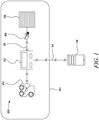
- FIG. 1 some components associated with a machine 102 are schematically illustrated.
- the machine 102 may be used for a variety of earth moving operations, such as dozing, grading, leveling, bulk material removal, or any other type of similar operation.
- the machine 102 may be a dozer, a loader, a dump truck, an excavator, and the like.
- the machine 102 may be any construction or mining related vehicle, a marine application vehicle, a power generation module, or any other type of a machine which may be suitable for application with various aspects of the present disclosure.
- the present disclosure is not limited by application area of the machine 102 in any manner.
- the machine 102 includes a number of ground engaging members 402 (see FIG. 4 ).
- the machine 102 may further include a frame 404 (shown in FIG. 4 ) supported over the ground engaging members 402.
- the machine 102 includes an engine 104 to provide power for operating the machine 102 as well as carrying out various auxiliary functions of the machine 102.
- the engine 104 may be any suitable type of an internal combustion engine suitable for application with various aspects of the present disclosure. The present disclosure is not limited by choice of the engine 104 in any manner.
- the engine 104 may further include a controller (not shown) associated with the engine 104.
- the controller may be any electronic controller, an engine control unit, a machine control unit, or a computing system.
- the controller may include a processor which operates to perform operations, executes control algorithms, stores data, retrieves data, gathers data, and/or performs any other computing or controlling task desired.
- the controller may be a single controller or may include more than one controller disposed to control various functions and/or features of the machine 102.
- the controller includes an associated memory.
- the controller may be otherwise connected to an external memory, such as a database or server.
- the associated memory and/or external memory may include, but are not limited to including, one or more of read only memory (ROM), random access memory (RAM), a portable memory, and the like.
- ROM read only memory
- RAM random access memory
- portable memory and the like.
- the present disclosure may also be envisioned without a controller. It should be contemplated that the present disclosure does not depend upon the controller for critical functional steps. The teachings of the present disclosure may be applied to machines with or without such controllers.
- the machine 102 includes various other components which may be required for the machine 102 to perform an intended function. However, such components are not being discussed as the present disclosure is not limited by any such components.
- the machine 102 includes one or more machine components 106.
- the machine component 106 is an air filter of the engine 104, a break wear sensor, and/or an implement wear sensor.
- the one or more machine components 106 have an associated operational characteristic.
- the operational characteristic may be any operational parameter which indicates about status of functioning of the machine component 106.
- operational characteristic of an air filter may be considered as an inlet pressure, an outlet pressure, or a pressure difference across the air filter. When the air filter gets clogged, the aforementioned parameters may change and provide values which may be outside of a normal operating range, or greater than threshold values.
- the machine 102 includes a system 100 for monitoring health status of the one or more machine components 106 on a real time basis.
- the system 100 includes the one or more machine components 106.
- the system 100 includes one or more sensor modules 108.
- the sensor module 108 is communicably coupled to each of the one or more machine components 106.
- the sensor module 108 may include one or more sensors which may detect operational characteristic of the machine component 106.
- the sensor module 108 generates a first signal 110 at regular predetermined intervals indicative of the operational characteristic.
- the regular predetermined intervals may be defined based on various factors such as, but not limited to, a type of the machine component 106, a current life of the machine component 106, a history of real time health status of the machine component 106, operative criticality of the machine component and the like. In an embodiment, a user may also set the regular predetermined interval based on application requirements.
- the sensor module 108 when the machine 100 includes the controller, the sensor module 108 may also be communicably coupled to the controller. In such an embodiment, the sensor module 108 may send the first signal 110 to the controller. In another embodiment, when the controller is not present, the sensor module 108 may be directly coupled to the engine 104.
- the system 100 includes one or more Internet of Things (IoT) module 112.
- the IoT module 112 includes a battery or a cell.
- the IoT module 112 may be defined as an electronic device embedded in parts that connect to wireless networks for sending and receiving data. Although only one IoT module 112 is illustrated herein, it should be contemplated that the present disclosure may use more than one IoT module 112.
- Each of the IoT module 112 is communicably coupled to the machine component 106.
- the machine component 106 may be associated with more than one IoT module 112.
- more than one machine component 106 may be associated with single IoT module 112.
- each of the IoT modules 112 is communicably coupled with the one or more sensor modules 108 and one other IoT module 112 either directly or indirectly.
- the IoT module 112 receives the first signal 110.
- the IoT module 112 converts the first signal 110 from analog format to digital format to generate a second signal 114.
- the second signal 114 is a high accuracy signal.
- the second signal 114 is indicative of the pressure difference between the inlet pressure and the outlet pressure of the air filter.
- the IoT module 112 transmits the second signal 114 wirelessly.
- the IoT module 112 may transmit the second signal 114 through any suitable wireless mode of communication, such as Bluetooth®, Wi-Fi®, internet connectivity, cellular networks, Near Field Communication (NFC), and the like.
- the system 100 further includes a mobile device 116.
- the mobile device 116 may be a cell phone, personal digital assistant, a smartphone, a tablet, a smartwatch, or any other suitable device which may be suitable for application with various aspects of the present disclosure.
- the mobile device 116 may also facilitate an alert, an audio message, a video message, a vibration alert, or any other such type of an alert to inform a user about a real time health status of the machine component 106.
- the mobile device 116 may be present with an operator of the machine 102.
- the mobile device 116 is communicably coupled to the one or more of IoT modules 112.
- the mobile device 116 receives the second signal 114.
- the mobile device 116 processes the second signal 114 to determine the real time health status of the machine component 106.
- processing the second signal 114 includes calculating a remaining useful life of the machine component 106.
- the mobile device 116 may be equipped with suitable hardware/software components to execute the processing step. Further, the mobile device 116 may display the real time health status on a display (not shown) associated with the mobile device 116, or any other display means such as another mobile device, a display screen coupled to the mobile device 116, and the like.
- the real time health status corresponds to an actual condition of operational health of the machine component 106.
- the real time health status may be defined based on various parameters which may be specific to a type of the machine component 106 being monitored.
- the real time health status may include one or more of a remaining useful life, a maintenance time period, a service procedure requirement for the machine component 106, and the like. It should be contemplated that the real time health status of the machine component 106 may include any other such parameter as well, and the present disclosure is not limited by any such parameters.
- FIG. 2 illustrates another embodiment of the system 100.
- the system 100 includes the machine 102, the engine 104, the machine component 106, the sensor module 108, the IoT module 112, and the mobile device 116.
- the sensor module 108 is communicably coupled to the machine component 106.
- the mobile device 116 is communicably coupled to the IoT module 112.
- the sensor module 108 generates the first signal 110 indicative of the operational characteristic of the machine component 106.
- the IoT module 112 receives the first signal 110 and converts the first signal 110 from analog format to digital format to generate the second signal 114.
- the IoT module 112 transmits the second signal 114 wirelessly.
- the mobile device 116 receives the second signal 114.
- the mobile device 116 transmits the second signal 114.
- the mobile device 116 may transmit the second signal 114 in a wireless manner.
- the system 100 further includes a remote server 118.
- the remote server 118 is communicably coupled to the mobile device 116.
- the remote server 118 may be any remote facility equipped with capabilities to transmit signals, receive signals, and execute processing steps.
- the remote server 118 may be a back office, a remote office location, a back-end server, or any other such facility.
- the remote server 118 receives the second signal 114 from the mobile device 116.
- the remote server 118 processes the second signal 114 to determine the real time health status of the machine component 106. In an embodiment, processing the second signal 114 includes calculating a remaining useful life of the machine component 106.
- the remote server 118 may further communicate the processed information to the mobile device 116.
- the mobile device 116 receives the real time health status of the machine component 106 from the remote server 118.
- the mobile device 116 displays the real time health status of the machine component 106 on the mobile device 116.
- the real time health status includes one or more of a remaining useful life, a maintenance time period, or a service procedure requirement for the machine component. It should be contemplated that the real time health status of the machine component 106 may include any other such parameter as well, and the present disclosure is not limited by any such parameters.
- the mobile device 116 may store a history of the real time health status of the machine component 106.
- the remote server 118 may store the history of the real time health status of the machine component 106.
- the remote server 118 may provide the mobile device with access to the historical data, if required.
- the IoT module 112 may also store the history of the real time health status of the machine component 106.
- the mobile device 116 may retrieve data from the IoT module 112.
- the mobile device 116 may use the retrieved data for further processing and analysis.
- the history of the real time health status of the machine component 106 may include previous failure events, operational data leading up to failure, patterns of operational data indicating potential failure etc. For example, for an air filter, the history may include clogging events, pressure values leading up to clogging event etc.
- the mobile device 116 displays the alert on the mobile device 116 when the real time health status of the machine component 106 is below a pre-determined threshold health status.
- the mobile device 116 may compare the determined real time health status of the machine component 106 with the pre-determined threshold health status, and display the alert based on the comparison.
- the mobile device 116 may display a text message indicating the real time health status of the machine component 106.
- the mobile device 116 suggests the corrective measure to be taken to improve the real time health status of the machine component 106.
- the mobile device 116 may be suitably provided with the pre-determined threshold health status based on various parameters including operating conditions, historical failure data, specification of the machine component 106, etc. After determining that the real time health status of the machine component 106 is unsatisfactory, or below the pre-determined threshold health status, the mobile device 116 may suggest the corrective measure to be take based on the comparison.
- the corrective measure may involve a service or maintenance procedure of the machine component 106, replacement of the machine component 106, adjusting operational conditions or parameters of the machine component 106 etc.
- FIG. 3 schematically illustrates the machine 102.
- the machine 102 includes the system 100 for monitoring the real time health status of the machine components 106.
- the system 100 includes multiple sensor modules 108 and multiple IoT modules 112.
- Each sensor module 108 is communicably coupled to at least one machine component 106. In the illustrated embodiment, the machine component 106 is coupled to two sensor modules 108. However, the machine component 106 may be coupled to any number of sensor modules 108.
- each sensor module 108 is communicably coupled to a corresponding IoT module 112.
- each IoT module 112 is communicably coupled to a corresponding sensor module 108 and another IoT module 112. In the illustrated example, each IoT module 112 is communicably coupled to two sensor modules 108.
- the IoT modules 112 create a mesh-type virtual network across the machine 102.
- the IoT modules 112 are interconnected to each other such that accessing one of the IoT modules 112 may provide access to information being carried by other Io
- the mobile device 116 may connect to one or more IoT modules 112 to access relevant information regarding the machine component 106.
- the mobile device 116 may have a Bluetooth® connection range shown by a dotted circle.
- the mobile device 116 may search for available IoT modules 112 within the Bluetooth® connection range and proceed to connect to the available IoT module 112.
- An exemplary application scenario may include the operator sitting inside an operator cabin (not shown). It may be counterproductive for the operator to go outside of the operator cabin to check the real time health status of the machine component 106 during an ongoing work cycle.
- the IoT module 112 may be provided near the operator cabin such that the IoT module 112 may be within a Bluetooth® connection range of the mobile device 116 being carried by the operator. Thus, the operator may access the real time health status of any machine component 106 located across the machine 102 conveniently.
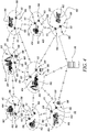
- FIG. 4 illustrates another exemplary scenario with respect to the present disclosure.
- multiple machine 102 may be working to complete an intended task.
- Each machine 102 includes one or more sensor modules 108 and one or more IoT module 112.
- the IoT modules 112 are interconnected to each other irrespective of the machine 102 to which the IoT module 112 is coupled with. Further, In the illustrated example, each machine 102 is communicably coupled to two IoT modules 112. Further, each IoT module 112 is in turn communicably coupled to two sensor modules 108.
- the IoT module 112 may receive information about the real time health status of the machine component 106 with which the IoT module 112 is coupled through the sensor module 108. Further, the IoT module 112 may receive information about the real time health status of the machine components 106 of other machines 102 through other IoT modules 112.
- the mobile device 116 may connect to one of the machines 102 via the respective IoT modules 112 using any suitable wireless connection methods.
- a user may access information about the real time health status of any machine component 106 coupled with any machine 102 through the mobile device 116 as all the IoT modules 112 are interconnected with each other.
- the mobile device 116 may be present at the back office or with a personnel in charge of the worksite, without limiting the scope of the present disclosure.
- FIG. 5 illustrates a method 500 of monitoring health status of the machine component 106 on the real time basis.
- the machine component 106 is the air filter of the engine 104, the break wear sensor, and/or the implement wear sensor.
- the sensor module 108 generates the first signal 110 indicative of the operational characteristic of the machine component 106.
- the sensor module 108 generates the first signal 110 at regular predetermined intervals.
- the Internet of Things (IoT) module 112 receives the first signal 110.
- the IoT module 112 converts the first signal 110 from analog format to digital format to generate the second signal 114.
- IoT Internet of Things
- the IoT module 112 transmits the second signal 114 wirelessly.
- the second signal 114 is indicative of the pressure difference between the inlet pressure and the outlet pressure of the air filter.
- the mobile device 116 receives the second signal 114.
- the mobile device 116 processes the second signal 114 to determine the real time health status of the machine component 106.
- processing the second signal 114 includes calculating the remaining useful life of the machine component 106.
- the IoT module 112 may also perform the processing step. In such case, the mobile device 116 may be used as a display unit.
- the mobile device 116 displays the real time health status of the machine component 106 on the mobile device 116.
- the real time health status may include the remaining useful life, the maintenance time period, and/or the service procedure requirement for the machine component 106.
- the mobile device 116 sends the second signal 114 to the remote server 118. Further, the remote server 118 processes the second signal 114 to determine the real time health status of the machine component 106. In an embodiment, processing the second signal 114 includes calculating a remaining useful life of the machine component 106.
- the method 500 may further include receiving the real time health status of the machine component 106 from the remote server 118 by the mobile device 116. The method 500 may further include displaying the real time health status of the machine component 106 on the mobile device 116 by the mobile device 116.
- the present disclosure provides the system 100 and the method 500 to monitor the health status of the machine component 106 in real time.
- the real time health status information provided by the system 100 can be used to provide alerts or suggest corrective measures to be taken.
- the corrective measures may include service requirement, replacement requirement, or any other measure which needs to be taken to improve the functioning health of the machine component 106 or eliminate machine downtime.
- the system 100 may include any type of sensor which can provide analog, digital, pulse width modulation, or current output signals during operation of machine operation. Further, data collected may be forwarded to back office for behavioral analysis of sensor operation. This analysis may further be used for maintenance/service/repair requirements.
- the mobile device 116 may have a mobile application installed therein. Such a mobile application may be used to monitor the real time health status of one or more machine components 106. For example, a machine may have multiple engine air filters. Such air filters may be indexed on the mobile application with respective identifiers. Further, a user may get notified about the real time health status through the mobile device 116 via a text message or any other visual indication techniques, audio alert, vibration alert, or any other such alert. Further, the mobile device 116 may also suggest corrective measures to be taken for maintaining health of the air filters. Numerous such applications of the present disclosure may be extended to various type of machine components. Thus, the present disclosure facilitates proactive approach of monitoring the real time health status of any machine component 106.
- the IoT modules 112 may have complementary connection terminals so that the IoT modules 112 may be connected between the sensor module 108 and the controller. In the embodiments, when there is no controller, the IoT module 112 may have appropriate connection terminals to connect to an intermediate component that is coupled to the sensor module 108. Thus, the IoT module 112 may act as a retrofittable aftermarket solution. In an embodiment, the IoT module 112 may be provided with backup battery arrangement to ensure that even when the time the machine 102 is not operational, the user may access the real time health status of various machine components 106.
Landscapes
- Engineering & Computer Science (AREA)
- Computer Networks & Wireless Communication (AREA)
- Signal Processing (AREA)
- Computing Systems (AREA)
- Health & Medical Sciences (AREA)
- General Health & Medical Sciences (AREA)
- General Physics & Mathematics (AREA)
- Automation & Control Theory (AREA)
- Physics & Mathematics (AREA)
- Medical Informatics (AREA)
- Biomedical Technology (AREA)
- Testing And Monitoring For Control Systems (AREA)
- Management, Administration, Business Operations System, And Electronic Commerce (AREA)
- Business, Economics & Management (AREA)
- Accounting & Taxation (AREA)
- Development Economics (AREA)
- Economics (AREA)
- General Business, Economics & Management (AREA)
Abstract
Description
- The present disclosure generally relates to monitoring health status of a machine component. More specifically, the present disclosure relates to monitoring the health status of the machine component on a real time basis.
- An important feature in modern work machines (e.g., fixed and mobile commercial machines, such as construction machines, fixed engine systems, marine-based machines, etc.) is detection and diagnosis of faults or errors in such machines. Machine faults may cause discomfort to operators handling the machines and may incur additional costs to business entities that use the machines in their particular commercial industry. Accordingly, systems have evolved to monitor and detect faults in the machines during operation.
- Currently, such machines are provided with various systems and sub-systems including various sensors & switches, which help in providing machine health information to engine & machine control units. However, this information may not be readily available to end users, and mostly only a failure notification is provided. For example, in case of air filters for an engine, the information is only available when the filters are in a choked/clogged condition and in need of replacement, resulting in machine downtime. Further, air flow restriction from the air filter can increase engine pumping work and reduce machine fuel economy. To avoid such situations, air filters may have to be replace or cleaned in due time which may require periodic monitoring of a health status of the air filter.
-
U.S. Patent Number 10,119,886 - Thus, the conventional machine systems lack a maintenance system which may provide information on operating parameters of serviceable components on a real time basis.
- In an aspect of the present disclosure, a method of monitoring health status of a machine component on a real time basis is provided. The method includes generating a first signal indicative of an operational characteristic of the machine component by a sensor module at regular predetermined intervals. The method also includes receiving the first signal by an Internet of Things (IoT) module. The method further includes converting the first signal from analog format to digital format by the IoT module to generate a second signal. The method includes transmitting the second signal by the IoT module wirelessly. The method also includes receiving the second signal by a mobile device. The method further includes processing the second signal by the mobile device to determine a real time health status of the machine component. Further, the method includes displaying the real time health status of the machine component on the mobile device.
- In another aspect of the present disclosure, a system for monitoring health status of one or more machine components of a machine on a real time basis is provided. Each of the one or more machine components has an associated operational characteristic. The system includes one or more sensor modules communicably coupled to each of the one of more machine components. The sensor module generates a first signal at regular predetermined intervals indicative of the operational characteristic. The system also includes one or more IoT modules communicably coupled to each other either directly or indirectly. Each of the one or more IoT modules is communicably coupled with the one or more sensor modules. Each of the one or more IoT modules receives the first signal and converts the first signal from analog format to digital format to generate a second signal. Each of the one or more IoT modules transmits the second signal wirelessly. The system also includes a mobile device communicably coupled to any one of the one or more IoT modules. The mobile device receives the second signal and processes the second signal to determine a real time health status of the machine component. The mobile device further displays the real time health status of the machine component on the mobile device.
- In yet another aspect of the present disclosure, a machine is provided. The machine includes a plurality of ground engaging members. The machine also includes a frame supported over the plurality of ground engaging members. The machine further includes one or more machine components having an associated operational characteristic. The machine includes a system for monitoring health status of the one or more machine components on a real time basis. The system includes one or more sensor modules communicably coupled to the machine component. The sensor module generates a first signal indicative of the operational characteristic at regular pre-determined intervals. The system also includes one or more IoT modules. Each of the one or more IoT modules is communicably coupled with the one or more sensor modules and another IoT module either directly or indirectly. Each of the one or more IoT modules receives the first signal and converts the first signal from analog format to digital format to generate a second signal. Each of the one or more IoT modules transmits the second signal wirelessly. The system further includes a mobile device communicably coupled to each of the one or more IoT modules. The mobile device receives the second signal and processes the second signal to determine a real time health status of the machine component. The mobile device further displays the real time health status of the machine component on the mobile device.
- Other features and aspects of this disclosure will be apparent from the following description and the accompanying drawings.
-
-
FIG. 1 shows a schematic view of a system to determine health status of a machine component on a real time basis, according to an aspect of the present disclosure; -
FIG. 2 shows a schematic view of another system to determine the real time health status of the machine component on a real time basis, according to an aspect of the present disclosure; -
FIG. 3 schematically illustrates a system to determine the real time health status of the machine component for a machine, according to an aspect of the present disclosure; -
FIG. 4 schematically illustrates multiple machines having a system to determine the real time health status of the machine component associated with a corresponding machine, according to an aspect of the present disclosure; and -
FIG. 5 is a flowchart for a method of monitoring the real time health status of the machine component, according to an aspect of the present disclosure. - Wherever possible, the same reference numbers will be used throughout the drawings to refer to same or like parts. Referring to
FIG. 1 , some components associated with amachine 102 are schematically illustrated. Themachine 102 may be used for a variety of earth moving operations, such as dozing, grading, leveling, bulk material removal, or any other type of similar operation. Themachine 102 may be a dozer, a loader, a dump truck, an excavator, and the like. Themachine 102 may be any construction or mining related vehicle, a marine application vehicle, a power generation module, or any other type of a machine which may be suitable for application with various aspects of the present disclosure. The present disclosure is not limited by application area of themachine 102 in any manner. - The
machine 102 includes a number of ground engaging members 402 (seeFIG. 4 ). Themachine 102 may further include a frame 404 (shown inFIG. 4 ) supported over theground engaging members 402. Themachine 102 includes anengine 104 to provide power for operating themachine 102 as well as carrying out various auxiliary functions of themachine 102. Theengine 104 may be any suitable type of an internal combustion engine suitable for application with various aspects of the present disclosure. The present disclosure is not limited by choice of theengine 104 in any manner. Theengine 104 may further include a controller (not shown) associated with theengine 104. The controller may be any electronic controller, an engine control unit, a machine control unit, or a computing system. The controller may include a processor which operates to perform operations, executes control algorithms, stores data, retrieves data, gathers data, and/or performs any other computing or controlling task desired. - The controller may be a single controller or may include more than one controller disposed to control various functions and/or features of the
machine 102. The controller includes an associated memory. The controller may be otherwise connected to an external memory, such as a database or server. The associated memory and/or external memory may include, but are not limited to including, one or more of read only memory (ROM), random access memory (RAM), a portable memory, and the like. The present disclosure may also be envisioned without a controller. It should be contemplated that the present disclosure does not depend upon the controller for critical functional steps. The teachings of the present disclosure may be applied to machines with or without such controllers. - The
machine 102 includes various other components which may be required for themachine 102 to perform an intended function. However, such components are not being discussed as the present disclosure is not limited by any such components. Themachine 102 includes one ormore machine components 106. Themachine component 106 is an air filter of theengine 104, a break wear sensor, and/or an implement wear sensor. The one ormore machine components 106 have an associated operational characteristic. The operational characteristic may be any operational parameter which indicates about status of functioning of themachine component 106. For example, operational characteristic of an air filter may be considered as an inlet pressure, an outlet pressure, or a pressure difference across the air filter. When the air filter gets clogged, the aforementioned parameters may change and provide values which may be outside of a normal operating range, or greater than threshold values. - The
machine 102 includes asystem 100 for monitoring health status of the one ormore machine components 106 on a real time basis. Thesystem 100 includes the one ormore machine components 106. Further, thesystem 100 includes one ormore sensor modules 108. Thesensor module 108 is communicably coupled to each of the one ormore machine components 106. Thesensor module 108 may include one or more sensors which may detect operational characteristic of themachine component 106. Thesensor module 108 generates afirst signal 110 at regular predetermined intervals indicative of the operational characteristic. The regular predetermined intervals may be defined based on various factors such as, but not limited to, a type of themachine component 106, a current life of themachine component 106, a history of real time health status of themachine component 106, operative criticality of the machine component and the like. In an embodiment, a user may also set the regular predetermined interval based on application requirements. In an embodiment, when themachine 100 includes the controller, thesensor module 108 may also be communicably coupled to the controller. In such an embodiment, thesensor module 108 may send thefirst signal 110 to the controller. In another embodiment, when the controller is not present, thesensor module 108 may be directly coupled to theengine 104. - The
system 100 includes one or more Internet of Things (IoT)module 112. In some examples, theIoT module 112 includes a battery or a cell. TheIoT module 112 may be defined as an electronic device embedded in parts that connect to wireless networks for sending and receiving data. Although only oneIoT module 112 is illustrated herein, it should be contemplated that the present disclosure may use more than oneIoT module 112. Each of theIoT module 112 is communicably coupled to themachine component 106. In an embodiment, themachine component 106 may be associated with more than oneIoT module 112. In another embodiment, more than onemachine component 106 may be associated withsingle IoT module 112. Further, each of theIoT modules 112 is communicably coupled with the one ormore sensor modules 108 and oneother IoT module 112 either directly or indirectly. - The
IoT module 112 receives thefirst signal 110. TheIoT module 112 converts thefirst signal 110 from analog format to digital format to generate asecond signal 114. Thesecond signal 114 is a high accuracy signal. In an embodiment, thesecond signal 114 is indicative of the pressure difference between the inlet pressure and the outlet pressure of the air filter. TheIoT module 112 transmits thesecond signal 114 wirelessly. TheIoT module 112 may transmit thesecond signal 114 through any suitable wireless mode of communication, such as Bluetooth®, Wi-Fi®, internet connectivity, cellular networks, Near Field Communication (NFC), and the like. - The
system 100 further includes amobile device 116. Themobile device 116 may be a cell phone, personal digital assistant, a smartphone, a tablet, a smartwatch, or any other suitable device which may be suitable for application with various aspects of the present disclosure. Themobile device 116 may also facilitate an alert, an audio message, a video message, a vibration alert, or any other such type of an alert to inform a user about a real time health status of themachine component 106. In some examples, themobile device 116 may be present with an operator of themachine 102. - The
mobile device 116 is communicably coupled to the one or more ofIoT modules 112. Themobile device 116 receives thesecond signal 114. Themobile device 116 processes thesecond signal 114 to determine the real time health status of themachine component 106. In an embodiment, processing thesecond signal 114 includes calculating a remaining useful life of themachine component 106. Themobile device 116 may be equipped with suitable hardware/software components to execute the processing step. Further, themobile device 116 may display the real time health status on a display (not shown) associated with themobile device 116, or any other display means such as another mobile device, a display screen coupled to themobile device 116, and the like. - The real time health status corresponds to an actual condition of operational health of the
machine component 106. The real time health status may be defined based on various parameters which may be specific to a type of themachine component 106 being monitored. The real time health status may include one or more of a remaining useful life, a maintenance time period, a service procedure requirement for themachine component 106, and the like. It should be contemplated that the real time health status of themachine component 106 may include any other such parameter as well, and the present disclosure is not limited by any such parameters. -
FIG. 2 illustrates another embodiment of thesystem 100. Thesystem 100 includes themachine 102, theengine 104, themachine component 106, thesensor module 108, theIoT module 112, and themobile device 116. Thesensor module 108 is communicably coupled to themachine component 106. Themobile device 116 is communicably coupled to theIoT module 112. Thesensor module 108 generates thefirst signal 110 indicative of the operational characteristic of themachine component 106. TheIoT module 112 receives thefirst signal 110 and converts thefirst signal 110 from analog format to digital format to generate thesecond signal 114. TheIoT module 112 transmits thesecond signal 114 wirelessly. Themobile device 116 receives thesecond signal 114. Themobile device 116 transmits thesecond signal 114. Themobile device 116 may transmit thesecond signal 114 in a wireless manner. - The
system 100 further includes aremote server 118. Theremote server 118 is communicably coupled to themobile device 116. Theremote server 118 may be any remote facility equipped with capabilities to transmit signals, receive signals, and execute processing steps. Theremote server 118 may be a back office, a remote office location, a back-end server, or any other such facility. Theremote server 118 receives thesecond signal 114 from themobile device 116. Theremote server 118 processes thesecond signal 114 to determine the real time health status of themachine component 106. In an embodiment, processing thesecond signal 114 includes calculating a remaining useful life of themachine component 106. Theremote server 118 may further communicate the processed information to themobile device 116. - In an embodiment, the
mobile device 116 receives the real time health status of themachine component 106 from theremote server 118. Themobile device 116 displays the real time health status of themachine component 106 on themobile device 116. The real time health status includes one or more of a remaining useful life, a maintenance time period, or a service procedure requirement for the machine component. It should be contemplated that the real time health status of themachine component 106 may include any other such parameter as well, and the present disclosure is not limited by any such parameters. - In an embodiment, the
mobile device 116 may store a history of the real time health status of themachine component 106. In another embodiment, theremote server 118 may store the history of the real time health status of themachine component 106. Theremote server 118 may provide the mobile device with access to the historical data, if required. In another embodiment, theIoT module 112 may also store the history of the real time health status of themachine component 106. Themobile device 116 may retrieve data from theIoT module 112. Themobile device 116 may use the retrieved data for further processing and analysis. The history of the real time health status of themachine component 106 may include previous failure events, operational data leading up to failure, patterns of operational data indicating potential failure etc. For example, for an air filter, the history may include clogging events, pressure values leading up to clogging event etc. - In another embodiment, the
mobile device 116 displays the alert on themobile device 116 when the real time health status of themachine component 106 is below a pre-determined threshold health status. Themobile device 116 may compare the determined real time health status of themachine component 106 with the pre-determined threshold health status, and display the alert based on the comparison. In an embodiment, themobile device 116 may display a text message indicating the real time health status of themachine component 106. - In another embodiment, the
mobile device 116 suggests the corrective measure to be taken to improve the real time health status of themachine component 106. Themobile device 116 may be suitably provided with the pre-determined threshold health status based on various parameters including operating conditions, historical failure data, specification of themachine component 106, etc. After determining that the real time health status of themachine component 106 is unsatisfactory, or below the pre-determined threshold health status, themobile device 116 may suggest the corrective measure to be take based on the comparison. The corrective measure may involve a service or maintenance procedure of themachine component 106, replacement of themachine component 106, adjusting operational conditions or parameters of themachine component 106 etc. -
FIG. 3 schematically illustrates themachine 102. Themachine 102 includes thesystem 100 for monitoring the real time health status of themachine components 106. Thesystem 100 includesmultiple sensor modules 108 andmultiple IoT modules 112. Eachsensor module 108 is communicably coupled to at least onemachine component 106. In the illustrated embodiment, themachine component 106 is coupled to twosensor modules 108. However, themachine component 106 may be coupled to any number ofsensor modules 108. Further, eachsensor module 108 is communicably coupled to acorresponding IoT module 112. Furthermore, eachIoT module 112 is communicably coupled to acorresponding sensor module 108 and anotherIoT module 112. In the illustrated example, eachIoT module 112 is communicably coupled to twosensor modules 108. TheIoT modules 112 create a mesh-type virtual network across themachine 102. TheIoT modules 112 are interconnected to each other such that accessing one of theIoT modules 112 may provide access to information being carried byother IoT modules 112. - The
mobile device 116 may connect to one or moreIoT modules 112 to access relevant information regarding themachine component 106. For example, as illustrated inFIG. 3 , themobile device 116 may have a Bluetooth® connection range shown by a dotted circle. Themobile device 116 may search foravailable IoT modules 112 within the Bluetooth® connection range and proceed to connect to theavailable IoT module 112. - An exemplary application scenario may include the operator sitting inside an operator cabin (not shown). It may be counterproductive for the operator to go outside of the operator cabin to check the real time health status of the
machine component 106 during an ongoing work cycle. In such a situation, theIoT module 112 may be provided near the operator cabin such that theIoT module 112 may be within a Bluetooth® connection range of themobile device 116 being carried by the operator. Thus, the operator may access the real time health status of anymachine component 106 located across themachine 102 conveniently. -
FIG. 4 illustrates another exemplary scenario with respect to the present disclosure. At an exemplary worksite,multiple machine 102 may be working to complete an intended task. Eachmachine 102 includes one ormore sensor modules 108 and one ormore IoT module 112. TheIoT modules 112 are interconnected to each other irrespective of themachine 102 to which theIoT module 112 is coupled with. Further, In the illustrated example, eachmachine 102 is communicably coupled to twoIoT modules 112. Further, eachIoT module 112 is in turn communicably coupled to twosensor modules 108. TheIoT module 112 may receive information about the real time health status of themachine component 106 with which theIoT module 112 is coupled through thesensor module 108. Further, theIoT module 112 may receive information about the real time health status of themachine components 106 ofother machines 102 throughother IoT modules 112. - The
mobile device 116 may connect to one of themachines 102 via therespective IoT modules 112 using any suitable wireless connection methods. A user may access information about the real time health status of anymachine component 106 coupled with anymachine 102 through themobile device 116 as all theIoT modules 112 are interconnected with each other. Further, themobile device 116 may be present at the back office or with a personnel in charge of the worksite, without limiting the scope of the present disclosure. -
FIG. 5 illustrates amethod 500 of monitoring health status of themachine component 106 on the real time basis. Themachine component 106 is the air filter of theengine 104, the break wear sensor, and/or the implement wear sensor. Atstep 502, thesensor module 108 generates thefirst signal 110 indicative of the operational characteristic of themachine component 106. Thesensor module 108 generates thefirst signal 110 at regular predetermined intervals. Atstep 504, the Internet of Things (IoT)module 112 receives thefirst signal 110. Atstep 506, theIoT module 112 converts thefirst signal 110 from analog format to digital format to generate thesecond signal 114. - At
step 508, theIoT module 112 transmits thesecond signal 114 wirelessly. In an embodiment, thesecond signal 114 is indicative of the pressure difference between the inlet pressure and the outlet pressure of the air filter. Atstep 510, themobile device 116 receives thesecond signal 114. Atstep 512, themobile device 116 processes thesecond signal 114 to determine the real time health status of themachine component 106. In an embodiment, processing thesecond signal 114 includes calculating the remaining useful life of themachine component 106. In another embodiment, theIoT module 112 may also perform the processing step. In such case, themobile device 116 may be used as a display unit. Atstep 514, themobile device 116 displays the real time health status of themachine component 106 on themobile device 116. In an embodiment, the real time health status may include the remaining useful life, the maintenance time period, and/or the service procedure requirement for themachine component 106. - Further, in some embodiments, the
mobile device 116 sends thesecond signal 114 to theremote server 118. Further, theremote server 118 processes thesecond signal 114 to determine the real time health status of themachine component 106. In an embodiment, processing thesecond signal 114 includes calculating a remaining useful life of themachine component 106. Themethod 500 may further include receiving the real time health status of themachine component 106 from theremote server 118 by themobile device 116. Themethod 500 may further include displaying the real time health status of themachine component 106 on themobile device 116 by themobile device 116. - The present disclosure provides the
system 100 and themethod 500 to monitor the health status of themachine component 106 in real time. The real time health status information provided by thesystem 100 can be used to provide alerts or suggest corrective measures to be taken. The corrective measures may include service requirement, replacement requirement, or any other measure which needs to be taken to improve the functioning health of themachine component 106 or eliminate machine downtime. It should be noted that thesystem 100 may include any type of sensor which can provide analog, digital, pulse width modulation, or current output signals during operation of machine operation. Further, data collected may be forwarded to back office for behavioral analysis of sensor operation. This analysis may further be used for maintenance/service/repair requirements. - The
mobile device 116 may have a mobile application installed therein. Such a mobile application may be used to monitor the real time health status of one ormore machine components 106. For example, a machine may have multiple engine air filters. Such air filters may be indexed on the mobile application with respective identifiers. Further, a user may get notified about the real time health status through themobile device 116 via a text message or any other visual indication techniques, audio alert, vibration alert, or any other such alert. Further, themobile device 116 may also suggest corrective measures to be taken for maintaining health of the air filters. Numerous such applications of the present disclosure may be extended to various type of machine components. Thus, the present disclosure facilitates proactive approach of monitoring the real time health status of anymachine component 106. - The present disclosure further provides ease of installation of the solution described herein. The
IoT modules 112 may have complementary connection terminals so that theIoT modules 112 may be connected between thesensor module 108 and the controller. In the embodiments, when there is no controller, theIoT module 112 may have appropriate connection terminals to connect to an intermediate component that is coupled to thesensor module 108. Thus, theIoT module 112 may act as a retrofittable aftermarket solution. In an embodiment, theIoT module 112 may be provided with backup battery arrangement to ensure that even when the time themachine 102 is not operational, the user may access the real time health status ofvarious machine components 106. - While aspects of the present disclosure have been particularly shown and described with reference to the embodiments above, it will be understood by those skilled in the art that various additional embodiments may be contemplated by the modification of the disclosed machines, systems and methods without departing from the spirit and scope of what is disclosed. Such embodiments should be understood to fall within the scope of the present disclosure as determined based upon the claims and any equivalents thereof.
Claims (20)
- A method of monitoring health status of a machine component on a real time basis, the method comprising:generating, by at least one sensor module, a first signal indicative of an operational characteristic of the machine component at regular predetermined intervals;receiving, by at least one Internet of Things (IoT) module, the first signal;converting, by the at least one IoT module, the first signal from analog format to digital format to generate a second signal;transmitting, by the at least one IoT module, the second signal wirelessly;receiving, by a mobile device, the second signal;processing, by the mobile device, the second signal to determine a real time health status of the machine component; anddisplaying, by the mobile device, the real time health status of the machine component on the mobile device.
- The method of claim 1, further including:sending, by the mobile device, the second signal to a remote server; andprocessing, at the remote server, the second signal to determine the real time health status of the machine component.
- The method of claim 1, further including:
displaying, by the mobile device, an alert when on the mobile device the real time health status of the machine component is below a pre-determined threshold health status. - The method of claim 1, wherein processing the second signal includes calculating a remaining useful life of the machine component.
- The method of claim 1, wherein the real time health status includes one or more of a remaining useful life, a maintenance time period, and a service procedure requirement for the machine component.
- The method of claim 1, further including:
suggesting, by the mobile device, a corrective measure to be taken to improve the real time health status of the machine component. - The method of claim 1, wherein the machine component is one or more of an air filter of an engine, a break wear sensor, and an implement wear sensor.
- The method of claim 7, wherein the second signal is indicative of a pressure difference between an inlet pressure and an outlet pressure of the air filter.
- A system for monitoring health status of one or more machine components of a machine on a real time basis, the system comprising:the one or more machine components, each of the one or more machine components having an associated operational characteristic;at least one sensor module communicably coupled to each of the one of more machine components, the sensor module configured to generate a first signal at regular predetermined intervals indicative of the operational characteristic;one or more IoT modules communicably coupled to each other either directly or indirectly, each of the one or more IoT modules communicably coupled with the at least one sensor module, each of the one or more IoT modules configured to:receive the first signal;convert the first signal from analog format to digital format to generate a second signal; andtransmit the second signal wirelessly; anda mobile device communicably coupled to any one of the one or more IoT modules, the mobile device configured to:receive the second signal;process the second signal to determine a real time health status of the machine component; anddisplay the real time health status of the machine component on the mobile device.
- The system of claim 9, wherein the machine component is one or more of an air filter of an engine, a break wear sensor, and an implement wear sensor.
- The system of claim 9, further including:
displaying, by the mobile device, an alert when on the mobile device the real time health status of the machine component is below a pre-determined threshold health status. - The system of claim 9, further including a remote server communicably coupled to the mobile device, the remote server configured to:receive the second signal from the mobile device; andprocess the second signal to determine the real time health status of the machine component.
- The system of claim 9, wherein the mobile device is further configured to:receive the real time health status of the machine component from the remote server; anddisplay the real time health status of the machine component on the mobile device.
- The system of claim 9, wherein the real time health status includes one or more of a remaining useful life, a maintenance time period, a service procedure requirement for the machine component.
- A machine comprising:a plurality of ground engaging members;a frame supported over the plurality of ground engaging members;one or more machine components having an associated operational characteristic; anda system for monitoring health status of the one or more machine components on a real time basis, the system comprising:at least one sensor module communicably coupled to the machine component, the sensor module configured to generate a first signal indicative of the operational characteristic at regular pre-determined intervals;one or more IoT modules, each of the one or more IoT modules communicably coupled with the at least one sensor module and at least one other IoT module either directly or indirectly, each of the one or more IoT modules configured to:receive the first signal;convert the first signal from analog format to digital format to generate a second signal; andtransmit the second signal wirelessly; anda mobile device communicably coupled to each of the one or more IoT modules, the mobile device configured to:receive the second signal;process the second signal to determine a real time health status of the machine component; anddisplay the real time health status of the machine component on the mobile device.
- The machine of claim 15, wherein the machine component is one or more of an air filter of an engine, a break wear sensor, and an implement wear sensor.
- The machine of claim 15, wherein the system is further configured to:
store, by the mobile device, a history of the real time health status of the machine component on the mobile device. - The machine of claim 15, wherein the system further includes a remote server communicably coupled to the mobile device, the remote server configured to:receive the second signal from the mobile device; andprocess the second signal to determine the real time health status of the machine component.
- The machine of claim 15, wherein the mobile device is further configured to:receive the real time health status of the machine component from the remote server; anddisplay the real time health status of the machine component on the mobile device.
- The machine of claim 15, wherein the real time health status includes one or more of a remaining useful life, a maintenance time period, a service procedure requirement for the machine component.
Applications Claiming Priority (1)
| Application Number | Priority Date | Filing Date | Title |
|---|---|---|---|
| IN202011020513 | 2020-05-15 |
Publications (1)
| Publication Number | Publication Date |
|---|---|
| EP3910432A1 true EP3910432A1 (en) | 2021-11-17 |
Family
ID=75639726
Family Applications (1)
| Application Number | Title | Priority Date | Filing Date |
|---|---|---|---|
| EP21169763.6A Withdrawn EP3910432A1 (en) | 2020-05-15 | 2021-04-22 | System and method for real time health monitoring of a machine component |
Country Status (4)
| Country | Link |
|---|---|
| US (1) | US20210356926A1 (en) |
| EP (1) | EP3910432A1 (en) |
| JP (1) | JP2021179988A (en) |
| CN (1) | CN113676508A (en) |
Families Citing this family (6)
| Publication number | Priority date | Publication date | Assignee | Title |
|---|---|---|---|---|
| EP4016222B1 (en) * | 2020-12-18 | 2024-09-04 | Honeywell International Inc. | Monitoring the remaining useful lifetime of an asset |
| US12275551B2 (en) | 2021-08-13 | 2025-04-15 | Mujin, Inc. | Robotic systems with multi-purpose labeling systems and methods |
| DE102022105249A1 (en) * | 2022-03-07 | 2023-09-07 | Bayerische Motoren Werke Aktiengesellschaft | PROCEDURE FOR CHECKING OBD RELEVANCE OF AN INPUT SIGNAL |
| US20250076842A1 (en) * | 2023-09-01 | 2025-03-06 | Rockwell Automation Technologies, Inc. | Human interface module (him) connectivity and interface for contextualized health statistics in an industrial automation environment |
| KR102940598B1 (en) | 2023-12-27 | 2026-03-18 | 상신브레이크주식회사 | Brake pad abrasion detection system for vehicle and its detection |
| WO2026070292A1 (en) * | 2024-09-30 | 2026-04-02 | 日立建機株式会社 | Component management device for work machine |
Citations (6)
| Publication number | Priority date | Publication date | Assignee | Title |
|---|---|---|---|---|
| GB2513456A (en) * | 2013-03-15 | 2014-10-29 | Fisher Rosemount Systems Inc | Mobile analysis of physical phenomena in a process plant |
| US20140379626A1 (en) * | 2013-06-20 | 2014-12-25 | Rockwell Automation Technologies, Inc. | Information platform for industrial automation stream-based data processing |
| US20180109651A1 (en) * | 2016-10-17 | 2018-04-19 | Fisher-Rosemount Systems, Inc. | Mobile Devices for Remote Access of Process Control Data |
| US20180142929A1 (en) * | 2016-11-23 | 2018-05-24 | Wipro Limited | Method and system for monitoring refrigeration system |
| US10119886B2 (en) | 2015-12-22 | 2018-11-06 | Cummins Filtration Ip, Inc. | Filtration monitoring systems |
| US20190245712A1 (en) * | 2018-02-05 | 2019-08-08 | Chengfu Yu | Smart panel device and method |
Family Cites Families (9)
| Publication number | Priority date | Publication date | Assignee | Title |
|---|---|---|---|---|
| US6587767B2 (en) * | 2001-09-21 | 2003-07-01 | Detroit Diesel Corporation | Maintenance alert system for heavy-duty trucks |
| US7444234B2 (en) * | 2007-01-31 | 2008-10-28 | Gm Global Technology Operations, Inc. | Method and apparatus for monitoring an intake air filter |
| US10064551B2 (en) * | 2012-04-04 | 2018-09-04 | Cardiocom, Llc | Health-monitoring system with multiple health monitoring devices, interactive voice recognition, and mobile interfaces for data collection and transmission |
| US20150369236A1 (en) * | 2014-06-18 | 2015-12-24 | Caterpillar Inc. | System and method for health determination of a machine component |
| US20160065653A1 (en) * | 2014-08-26 | 2016-03-03 | Fujitsu Limited | Internet of things (iot) device configuration construction |
| WO2018031403A1 (en) * | 2016-08-08 | 2018-02-15 | 3M Innovative Properties Company | Air filter condition sensing |
| CN107380202B (en) * | 2017-07-31 | 2019-10-08 | 株洲中车轨道交通装备有限公司 | Based on NB-IoT net rail vehicle Spindle Status monitoring method and system |
| US11182987B2 (en) * | 2018-02-08 | 2021-11-23 | Geotab Inc. | Telematically providing remaining effective life indications for operational vehicle components |
| US20210052999A1 (en) * | 2019-08-21 | 2021-02-25 | Pratt & Whitney Canada Corp. | Method and system for monitoring a fluid system configured to operate with a filter |
-
2021
- 2021-04-22 EP EP21169763.6A patent/EP3910432A1/en not_active Withdrawn
- 2021-05-10 JP JP2021079701A patent/JP2021179988A/en active Pending
- 2021-05-10 CN CN202110504625.1A patent/CN113676508A/en active Pending
- 2021-05-13 US US17/319,408 patent/US20210356926A1/en not_active Abandoned
Patent Citations (6)
| Publication number | Priority date | Publication date | Assignee | Title |
|---|---|---|---|---|
| GB2513456A (en) * | 2013-03-15 | 2014-10-29 | Fisher Rosemount Systems Inc | Mobile analysis of physical phenomena in a process plant |
| US20140379626A1 (en) * | 2013-06-20 | 2014-12-25 | Rockwell Automation Technologies, Inc. | Information platform for industrial automation stream-based data processing |
| US10119886B2 (en) | 2015-12-22 | 2018-11-06 | Cummins Filtration Ip, Inc. | Filtration monitoring systems |
| US20180109651A1 (en) * | 2016-10-17 | 2018-04-19 | Fisher-Rosemount Systems, Inc. | Mobile Devices for Remote Access of Process Control Data |
| US20180142929A1 (en) * | 2016-11-23 | 2018-05-24 | Wipro Limited | Method and system for monitoring refrigeration system |
| US20190245712A1 (en) * | 2018-02-05 | 2019-08-08 | Chengfu Yu | Smart panel device and method |
Also Published As
| Publication number | Publication date |
|---|---|
| CN113676508A (en) | 2021-11-19 |
| US20210356926A1 (en) | 2021-11-18 |
| JP2021179988A (en) | 2021-11-18 |
Similar Documents
| Publication | Publication Date | Title |
|---|---|---|
| EP3910432A1 (en) | System and method for real time health monitoring of a machine component | |
| US10657450B2 (en) | Systems and methods for machine diagnostics based on stored machine data and available machine telematic data | |
| US9678845B2 (en) | Abnormality diagnostic system and industrial machinery | |
| US9366011B2 (en) | Work machine management device | |
| JP6675297B2 (en) | Information processing method, information processing system, and information processing apparatus | |
| US11403890B2 (en) | Filter element analysis system and associated methods | |
| KR101819160B1 (en) | Working machine and working machine monitoring system | |
| KR20040029081A (en) | Work machine maintenance system | |
| CN105026214A (en) | Abnormal information control device for construction machinery | |
| US11935337B2 (en) | Filter element analysis system and associated methods | |
| US7493482B2 (en) | Self-configurable information management system | |
| JP2011038273A (en) | Remote diagnosis system for working machine | |
| JP3735068B2 (en) | Travel service schedule creation method, creation system, and creation device | |
| CN112025703B (en) | Robot self-diagnosis method, device and system | |
| JP2015084176A (en) | Fault diagnostic apparatus and active machine | |
| JP5706284B2 (en) | Abnormality diagnosis system for work machines | |
| JP2013140624A (en) | Anomaly diagnostic device and industrial machine | |
| US12192286B2 (en) | Systems and methods for remote industrial machine communciation system diagnostics and solutions | |
| CA2911305A1 (en) | Method and system for managing a mobile equipment fleet | |
| US20260086549A1 (en) | Predictive failure analysis system and method | |
| Minh et al. | System for recognising and monitoring the technical condition of construction machines | |
| CN113955143B (en) | A health monitoring system based on local hydraulic energy integration system | |
| Nachshon et al. | Vehicle Conditions Based Maintenance (CBM) of Electronic Body Mounted Components based on Dynamic Statistical approach (Final) | |
| JP2018119257A (en) | Alarm information summarization system of work machine | |
| JPH04239370A (en) | System state information response device |
Legal Events
| Date | Code | Title | Description |
|---|---|---|---|
| PUAI | Public reference made under article 153(3) epc to a published international application that has entered the european phase |
Free format text: ORIGINAL CODE: 0009012 |
|
| STAA | Information on the status of an ep patent application or granted ep patent |
Free format text: STATUS: THE APPLICATION HAS BEEN PUBLISHED |
|
| AK | Designated contracting states |
Kind code of ref document: A1 Designated state(s): AL AT BE BG CH CY CZ DE DK EE ES FI FR GB GR HR HU IE IS IT LI LT LU LV MC MK MT NL NO PL PT RO RS SE SI SK SM TR |
|
| B565 | Issuance of search results under rule 164(2) epc |
Effective date: 20211006 |
|
| STAA | Information on the status of an ep patent application or granted ep patent |
Free format text: STATUS: REQUEST FOR EXAMINATION WAS MADE |
|
| 17P | Request for examination filed |
Effective date: 20220506 |
|
| RBV | Designated contracting states (corrected) |
Designated state(s): AL AT BE BG CH CY CZ DE DK EE ES FI FR GB GR HR HU IE IS IT LI LT LU LV MC MK MT NL NO PL PT RO RS SE SI SK SM TR |
|
| STAA | Information on the status of an ep patent application or granted ep patent |
Free format text: STATUS: EXAMINATION IS IN PROGRESS |
|
| 17Q | First examination report despatched |
Effective date: 20230515 |
|
| STAA | Information on the status of an ep patent application or granted ep patent |
Free format text: STATUS: THE APPLICATION HAS BEEN WITHDRAWN |
|
| 18W | Application withdrawn |
Effective date: 20250114 |