EP3910402A2 - Vibrating mirror element and optical scanner - Google Patents
Vibrating mirror element and optical scanner Download PDFInfo
- Publication number
- EP3910402A2 EP3910402A2 EP21168859.3A EP21168859A EP3910402A2 EP 3910402 A2 EP3910402 A2 EP 3910402A2 EP 21168859 A EP21168859 A EP 21168859A EP 3910402 A2 EP3910402 A2 EP 3910402A2
- Authority
- EP
- European Patent Office
- Prior art keywords
- mirror
- beams
- pair
- mirror part
- vibration suppression
- Prior art date
- Legal status (The legal status is an assumption and is not a legal conclusion. Google has not performed a legal analysis and makes no representation as to the accuracy of the status listed.)
- Pending
Links
Images




Classifications
-
- B—PERFORMING OPERATIONS; TRANSPORTING
- B81—MICROSTRUCTURAL TECHNOLOGY
- B81B—MICROSTRUCTURAL DEVICES OR SYSTEMS, e.g. MICROMECHANICAL DEVICES
- B81B3/00—Devices comprising flexible or deformable elements, e.g. comprising elastic tongues or membranes
- B81B3/0035—Constitution or structural means for controlling the movement of the flexible or deformable elements
- B81B3/004—Angular deflection
-
- G—PHYSICS
- G02—OPTICS
- G02B—OPTICAL ELEMENTS, SYSTEMS OR APPARATUS
- G02B26/00—Optical devices or arrangements for the control of light using movable or deformable optical elements
- G02B26/08—Optical devices or arrangements for the control of light using movable or deformable optical elements for controlling the direction of light
- G02B26/10—Scanning systems
- G02B26/105—Scanning systems with one or more pivoting mirrors or galvano-mirrors
-
- B—PERFORMING OPERATIONS; TRANSPORTING
- B81—MICROSTRUCTURAL TECHNOLOGY
- B81B—MICROSTRUCTURAL DEVICES OR SYSTEMS, e.g. MICROMECHANICAL DEVICES
- B81B3/00—Devices comprising flexible or deformable elements, e.g. comprising elastic tongues or membranes
- B81B3/0035—Constitution or structural means for controlling the movement of the flexible or deformable elements
- B81B3/004—Angular deflection
- B81B3/0048—Constitution or structural means for controlling angular deflection not provided for in groups B81B3/0043 - B81B3/0045
-
- G—PHYSICS
- G02—OPTICS
- G02B—OPTICAL ELEMENTS, SYSTEMS OR APPARATUS
- G02B26/00—Optical devices or arrangements for the control of light using movable or deformable optical elements
- G02B26/08—Optical devices or arrangements for the control of light using movable or deformable optical elements for controlling the direction of light
- G02B26/0816—Optical devices or arrangements for the control of light using movable or deformable optical elements for controlling the direction of light by means of one or more reflecting elements
- G02B26/0833—Optical devices or arrangements for the control of light using movable or deformable optical elements for controlling the direction of light by means of one or more reflecting elements the reflecting element being a micromechanical device, e.g. a MEMS mirror, DMD
-
- G—PHYSICS
- G02—OPTICS
- G02B—OPTICAL ELEMENTS, SYSTEMS OR APPARATUS
- G02B26/00—Optical devices or arrangements for the control of light using movable or deformable optical elements
- G02B26/08—Optical devices or arrangements for the control of light using movable or deformable optical elements for controlling the direction of light
- G02B26/0816—Optical devices or arrangements for the control of light using movable or deformable optical elements for controlling the direction of light by means of one or more reflecting elements
- G02B26/0833—Optical devices or arrangements for the control of light using movable or deformable optical elements for controlling the direction of light by means of one or more reflecting elements the reflecting element being a micromechanical device, e.g. a MEMS mirror, DMD
- G02B26/0858—Optical devices or arrangements for the control of light using movable or deformable optical elements for controlling the direction of light by means of one or more reflecting elements the reflecting element being a micromechanical device, e.g. a MEMS mirror, DMD the reflecting means being moved or deformed by piezoelectric means
-
- B—PERFORMING OPERATIONS; TRANSPORTING
- B81—MICROSTRUCTURAL TECHNOLOGY
- B81B—MICROSTRUCTURAL DEVICES OR SYSTEMS, e.g. MICROMECHANICAL DEVICES
- B81B2201/00—Specific applications of microelectromechanical systems
- B81B2201/04—Optical MEMS
- B81B2201/042—Micromirrors, not used as optical switches
Definitions
- the disclosure relates to a vibrating mirror element and an optical scanner.
- Patent Document 1 discloses an optical scanner including a substrate, a piezoelectric film, a twisted beam, and a mirror part.
- the optical scanner disclosed in Patent Document 1 is configured so that the mirror part supported by the twisted beam is swung by use of a plate wave excited in the substrate by the piezoelectric film.
- the substrate has a frame-like shape provided with an opening, and the mirror part is provided inside the opening via the twisted beam.
- one end of the substrate disclosed in Patent Document 1 is supported in a cantilevered manner by a support member.
- Patent Document 1 Japanese Patent Laid-open No. 2006-293116
- the disclosure provides a vibrating mirror element and an optical scanner in which the mirror part is able to be stably swung while an increase in overall size of the vibrating mirror element is suppressed even if the mirror part is increased in size.
- a vibrating mirror element includes: a mirror part reflecting light; a substrate made of metal and including: a pair of beams each having a first end and a second end, a support supporting the first end of each of the pair of beams, and a torsion part swingably supporting the mirror part; a driving source provided on the support and generating a plate wave that swings the mirror part; and a vibration suppression part suppressing vibration transmitted to the pair of beams by abutting against the pair of beams.
- the torsion part extends in a second direction orthogonal to a first direction in which the pair of beams extends in a direction along a surface of the mirror part, and is connected to each of the pair of beams.
- the vibration suppression part is configured to suppress the vibration transmitted to the pair of beams by abutting against the pair of beams at a position between a second mirror end among ends of the mirror part that is opposite a first mirror end near the support and the torsion part in the first direction.
- the vibrating mirror element according to the first aspect of the disclosure includes the substrate made of metal and including the pair of beams, the support supporting the first ends of the pair of beams, and the torsion part swingably supporting the mirror part. Accordingly, since the first ends of the pair of beams are supported by the support, unlike a configuration in which the mirror part is arranged inside an opening provided in a frame-shaped substrate, even if the mirror part is increased in size, the mirror part is able to be prevented from abutting against the substrate at the second end side. Therefore, an increase in overall size of the vibrating mirror element is able to be suppressed while the mirror part is increased in size.
- the vibration suppression part that suppresses the vibration transmitted to the pair of beams by abutting against the pair of beams is provided at the position between the second mirror end and the torsion part, not only the vibration for swinging the mirror part about the swing axis but also the vibration in the direction orthogonal to the surface of the mirror part is able to be prevented from being transmitted to the mirror part via the torsion part. Therefore, it is possible to prevent that a swing angle of the mirror part deviates from a predetermined swing angle range due to the vibration that causes the mirror part to swing in the direction orthogonal to the surface of the mirror part. As a result, even if the mirror part is increased in size, the mirror part is able to be stably swung while an increase in overall size of the vibrating mirror element is suppressed.
- a holding member is further included that holds the support and each of the pair of beams.
- the holding member is configured to hold each of the pair of beams at a position where the vibration suppression part abuts against the pair of beams or at a position nearer the second end than the position where the vibration suppression part abuts against the pair of beams.
- the vibration suppression part includes: a first vibration suppression part suppressing vibration by abutting against one of the pair of beams, and a second vibration suppression part provided separately from the first vibration suppression part and suppressing vibration by abutting against the other of the pair of beams.
- Each of the first vibration suppression part and the second vibration suppression part is provided separately from the substrate and the holding member.
- the holding member has a carrying surface carrying the first vibration suppression part and the second vibration suppression part. The carrying surface is formed so as to extend in the first direction.
- the mirror part is able to be relatively stably swung.
- the mirror part is configured so that a first distance from the torsion part to the second mirror end in the first direction is equal to or greater than a second distance from the torsion part to the second end in the first direction.
- the vibration suppression part is configured so that a third distance from the torsion part to an end of the vibration suppression part near the second end in the first direction is less than the first distance.
- the end of the vibration suppression part near the second mirror end is able to be prevented from being arranged farther from the torsion part than the second end of the mirror part in the first direction.
- an increase in the size of the vibrating mirror element in the first direction is able to be suppressed.
- the mirror part is provided separately from the substrate.
- the substrate further includes a mirror part arrangement part connected to the torsion part, the mirror part being arranged in the mirror part arrangement part.
- the torsion part is provided so as to extend in the second direction so as to overlap the mirror part, and is connected with the mirror part arrangement part at a position overlapping the mirror part in the second direction.
- the mirror part and the mirror part arrangement part are joined at at least two places by an adhesive having elasticity.
- an adhesive having elasticity for example, even if the mirror part and the mirror part arrangement part are made of different materials and have different linear expansion coefficients from each other, the occurrence of distortion in the mirror part due to the difference in linear expansion coefficient between the mirror part and the mirror part arrangement part is able to be suppressed. As a result, it is possible to prevent that a scanning range of the light scanned by the mirror part is different from a predetermined scanning range due to distortion of the mirror part.
- the adhesive joins the mirror part and the mirror part arrangement part at least at two places at substantially equal distances from a center of gravity of the mirror part or from a center of a surface of the mirror part.
- the mirror part arrangement part is thinned and formed into a beam shape so as to have a symmetrical mass on a reference plane containing the center of gravity of the mirror part or the center of the surface of the mirror part.
- a weight member is provided on the driving source or the pair of beams.
- a treatment preventing reflection of the light reflected by the mirror part is applied to at least one of a portion of the substrate in the vicinity of the mirror part and a surface of the driving source.
- An optical scanner includes: a light source irradiating light; a mirror part reflecting the light irradiated from the light source; a substrate made of metal and including: a pair of beams each having a first end and a second end, a support supporting the first end of each of the pair of beams, and a torsion part swingably supporting the mirror part; a driving source provided on the support and generating a plate wave that swings the mirror part; and a vibration suppression part suppressing vibration transmitted to the pair of beams by abutting against the pair of beams.
- the torsion part extends in a second direction orthogonal to a first direction in which the pair of beams extends in a direction along a surface of the mirror part, and is connected to each of the pair of beams.
- the vibration suppression part is configured to suppress the vibration transmitted to the pair of beams by abutting against the pair of beams at a position between a second mirror end among ends of the mirror part that is opposite a first mirror end near the support and the torsion part in the first direction.
- the optical scanner according to the second aspect of the disclosure includes the substrate made of metal and including the pair of beams, the support supporting the first ends of the pair of beams, and the torsion part swingably supporting the mirror part, as well as the vibration suppression part configured to suppress the vibration transmitted to the pair of beams by abutting against the pair of beams at the position between the second mirror end and the torsion part. Accordingly, like the vibrating mirror element of the first aspect, even if the mirror part is increased in size, the mirror part is able to be stably swung while an increase in overall size of the vibrating mirror element is suppressed.
- the vibrating mirror element and the optical scanner are able to be provided in which the mirror part is able to be stably swung while an increase in overall size of the vibrating mirror element is suppressed even if the mirror part is increased in size.
- FIG. 1 to FIG. 8 a configuration of a vibrating mirror element 2 and a configuration of an optical scanner 100 including the vibrating mirror element 2 according to one embodiment are described.
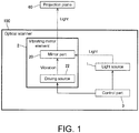
- the optical scanner 100 includes a light source 1, a vibrating mirror element 2, and a control part 3.
- the optical scanner 100 is configured to irradiate a projection plane 60 with light.
- the light source 1 is configured to output light. Specifically, the light source 1 is configured to irradiate, via a lens or the like, a mirror part 20 included in the vibrating mirror element 2.
- the light source 1 includes, for example, a light emitting diode (LED) or a laser diode (LD).
- the vibrating mirror element 2 is configured so that the light irradiated from the light source 1 is reflected by the mirror part 20 so as to be projected onto the projection plane 60 while the mirror part 20 is swung by a plate wave generated by a driving source 22. A detailed configuration of the vibrating mirror element 2 will be described later.
- the control part 3 is configured to control irradiation of laser light by the light source 1. Specifically, the control part 3 is configured to control the timing of each of blue laser light, red laser light, and green laser light irradiated from the light source 1.
- the control part 3 is configured to control each part of the optical scanner 100.
- the control part 3 is configured to acquire from the outside a video signal to be projected onto the projection plane 60.
- the control part 3 is configured to control the irradiation of laser light by the light source 1 based on the acquired video signal.
- the control part 3 includes, for example, a processor such as a central processing unit (CPU).
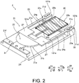
- the vibrating mirror element 2 includes the mirror part 20, a substrate 21, the driving source 22, a vibration suppression part, and a holding member 24.
- a direction orthogonal to a surface of the mirror part 20 is taken as a Z direction
- an upward direction is taken as a Z1 direction
- a downward direction is taken as a Z2 direction.
- Two directions orthogonal to each other in a plane orthogonal to the Z direction are taken as an X direction and a Y direction, respectively.
- One side of the X direction is taken as an X1 direction and the other side thereof is taken as an X2 direction.
- One side of the Y direction is taken as a Y1 direction and the other side thereof is taken as a Y2 direction.
- the mirror part 20 is configured to reflect the light irradiated from the light source 1.
- the mirror part 20 has a rectangular shape.
- the mirror part 20 is made of, for example, an aluminum material.
- the mirror part 20 is provided separately from the substrate 21.
- the mirror part 20 is provided in a mirror part arrangement part 25. In the example shown in FIG. 2 , the mirror part 20 is shown with hatching for convenience.
- the substrate 21 includes a pair of beams 21a, a support 21b, and a torsion part 21c.
- the substrate 21 includes the mirror part arrangement part 25 in which the mirror part 20 is arranged.
- the substrate 21 is made of, for example, a stainless steel material having a flat plate shape.
- the pair of beams 21a each have a first end 121a and a second end 121b. Each of the first ends 121a is supported by the support 21b. In the present embodiment, the pair of beams 21a is supported by the support 21b via a weight member 27. That is, the first end 121a is a portion connected with the weight member 27. The second end 121b is an end of the pair of beams 21a that is not connected to the weight member 27 in a first direction (Y direction). In the example shown in FIG. 2 , a holding part 21d held by the holding member 24 is provided on the second end 121b side of the pair of beams 21a. The holding part 21d is a portion of the pair of beams 21a.
- the holding part 21d is formed by increasing a width of the second end 121b side of the pair of beams 21a in the X direction.
- the holding part 21d is held by the holding member 24, for example, by being screwed thereto.
- the holding part 21d is provided with a through hole 30 penetrating in the Z direction.
- the support 21b is configured to support the first end 121a of each of the pair of beams 21a.
- the support 21b is provided with the driving source 22.
- the support 21b includes a driving source support 21e that supports the driving source 22, and the driving source 22 is arranged in the driving source support 21e.
- the driving source support 21e has a semicircular shape, like the driving source 22.
- the support 21b includes a holding part 21f at an end on the side that does not support the pair of beams 21a in the first direction (Y direction).
- the support 21b is held by the holding member 24, for example, by being screwed thereto.
- the holding part 21f is provided with a through hole 31 penetrating in the Z direction.
- the torsion part 21c swingably supports the mirror part 20.
- the torsion part 21c extends in a second direction (X direction) orthogonal to the first direction (Y direction) in which the pair of beams 21a extends in a direction along the surface of the mirror part 20.
- the torsion part 21c has a columnar shape.
- the torsion part 21c is provided as a pair. One of the pair of torsion parts 21c is connected with one of the pair of beams 21a, and the other torsion part 21c is connected to the other beam 21a. Each of the pair of torsion parts 21c is connected to the mirror part arrangement part 25.
- the mirror part arrangement part 25 is configured so that the mirror part 20 is arranged therein.
- the mirror part arrangement part 25 is connected to the pair of beams 21a via the torsion part 21c. A detailed configuration of the mirror part arrangement part 25 will be described later.
- the driving source 22 is configured to generate the plate wave that swings the mirror part 20.
- the driving source 22 includes, for example, a piezoelectric element.
- the piezoelectric element includes, for example, lead zirconate titanate (PZT).
- PZT lead zirconate titanate
- FIG. 2 PZT having a semicircular shape is provided as the driving source 22 on the substrate 21.
- the vibration suppression part is configured to suppress vibration transmitted to the pair of beams 21a by abutting against the pair of beams 21a.
- the vibration suppression part includes: a first vibration suppression part 23a, suppressing vibration by abutting against one of the pair of beams 21a; and a second vibration suppression part 23b, provided separately from the first vibration suppression part 23a and suppressing vibration by abutting against the other of the pair of beams 21a.
- Each of the first vibration suppression part 23a and the second vibration suppression part 23b is provided separately from the substrate 21 and the holding member 24.
- Each of the first vibration suppression part 23a and the second vibration suppression part 23b has an abutting surface 123a (see FIG. 5 ) abutting against the beam 21a. Details of positions where the first vibration suppression part 23a and the second vibration suppression part 23b abut against the pair of beams 21a or the like will be described later.
- the holding member 24 is configured to hold the support 21b. As shown in FIG. 2 , the holding member 24 holds the holding part 21f provided at the end of the support 21b on the side that does not support the pair of beams 21a in the first direction (Y direction). The holding member 24 is configured to hold each of the pair of beams 21a. As shown in FIG. 2 , the holding member 24 is configured to hold the holding part 21d of the pair of beams 21a.
- the holding member 24 is configured to hold each of the pair of beams 21a at a position where the vibration suppression part abuts against the pair of beams 21a or at a position nearer the second end 121b than the position where the vibration suppression part abuts against the pair of beams 21a.
- the holding member 24 holds each of the pair of beams 21a at the position nearer the second end 121b than the position where the vibration suppression part abuts against the pair of beams 21a.
- the holding member 24 has a carrying surface 24a carrying the first vibration suppression part 23a and the second vibration suppression part 23b.
- the carrying surface 24a is formed so as to extend in the first direction (Y direction).
- the carrying surface 24a is portion of a surface of the holding member 24 on the Z1 direction side, extending in a direction (Y direction) in which the pair of beams 21a extends below (Z2 direction side) the pair of beams 21a.
- the substrate 21 has a U-shape in plan view.
- the holding member 24 also has a U-shape, like the substrate 21.
- the driving source 22 or the pair of beams 21a is provided with the weight member 27.
- the weight member 27 is provided integrally with the substrate 21 on the first end 121a side of the pair of beams 21a. Specifically, the weight member 27 is integrally provided on the substrate 21 by increasing the size of the first end 121a side in the X direction.
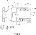
- the mirror part 20 is configured so that a first distance D1 from the torsion part 21c to a second mirror end 20b in the first direction (Y direction) is equal to or greater than a second distance D2 from the torsion part 21c to the second end 121b in the first direction.
- a length from the center of the torsion part 21c to the second mirror end 20b in the Y direction is taken as the first distance D1.
- a length from the center of the torsion part 21c to the second end 121b in the Y direction is taken as the second distance D2.
- the torsion part 21c is connected to the mirror part arrangement part 25 at a position not overlapping the mirror part 20 in the second direction (X direction). Specifically, the torsion part 21c is connected to the mirror part arrangement part 25 at a position where a distance D3 from the beam 21a to an end 20c of the mirror part 20 in the X direction is equal to a length D4 of the torsion part 21c in the X direction.
- the mirror part 20 is swung about a swing axis Ax so as to have a predetermined swing angle R.
- the mirror part 20 is swung about the swing axis Ax by the plate wave generated by the driving source 22.
- the driving source 22 by expansion and contraction of the driving source 22 in a direction (direction parallel to an XY plane) parallel to a surface of the substrate 21, the substrate 21 is bent in the Z direction, thereby generating the plate wave.
- the plate wave generated by the driving source 22 is transmitted to the torsion part 21c via the pair of beams 21a.
- the torsion part 21c swings the mirror part arrangement part 25 by being twisted by the plate wave transmitted via the pair of beams 21a.
- the mirror part arrangement part 25 swings the mirror part 20 by being swung by the torsion part 21c.
- the torsion part 21c is arranged so as to be at a position corresponding to an antinode portion or a node portion of the plate wave generated by the driving source 22.
- the plate wave includes a symmetric plate wave and an asymmetric plate wave.
- a maximum point of amplitude is the antinode portion and a minimum point of amplitude is the node portion.
- a portion where displacement becomes maximum is the antinode portion, and a portion where displacement becomes minimum is the node portion.
- the mirror part 20 and the mirror part arrangement part 25 are joined at at least two places by an adhesive 26 having elasticity. Since the mirror part 20 and the mirror part arrangement part 25 are joined by the adhesive 26 having elasticity, they are joined with a slight gap therebetween in the Z direction, as shown in FIG. 4 . Accordingly, when the torsion part 21c is twisted, it is possible to prevent the torsion part 21c from abutting against the mirror part 20, and the mirror part 20 is able to be stably swung at the predetermined swing angle R.
- FIG. 4 does not show a cross section, and hatches are added to make it easy to identify the mirror part 20, the torsion part 21c, the mirror part arrangement part 25, and the adhesive 26.
- the vibration suppression part is configured to suppress the vibration transmitted to the pair of beams 21a by abutting against the pair of beams 21a at a position between the second mirror end 20b among the ends of the mirror part 20 that is opposite a first mirror end 20a near the support 21b and the torsion part 21c in the first direction (Y direction).
- the vibration suppression part is configured to suppress transmission of the vibration that swings the substrate 21 in the Z direction to the pair of beams 21a.
- the first vibration suppression part 23a abuts against the beam on the X2 direction side among the pair of beams 21a from the Z2 direction side.
- the position of the first vibration suppression part 23a in the first direction (Y direction) is adjusted so that, in the abutting surface 123a of the first vibration suppression part 23a abutting against the beam, an abutting portion 123b of an end on the Y1 direction side is located between the second mirror end 20b and the torsion part 21c.
- the position of the abutting portion 123b is determined by the size of the mirror part 20, the thickness and length of the torsion part 21c, and the like.
- the second vibration suppression part 23b abuts against the beam on the X1 direction side among the pair of beams 21a.
- the position of the second vibration suppression part 23b is adjusted in the same manner as the first vibration suppression part 23a.
- the first vibration suppression part 23a and the second vibration suppression part 23b are configured to suppress the occurrence of an unwanted vibration mode or suppress the intensity by adjusting a length (length from the abutting portion 123b to the first end 121a) of a vibrating portion of the pair of beams 21a.
- the first vibration suppression part 23a is configured so that a third distance D5 from the torsion part 21c to an end of the first vibration suppression part 23a near the second end 121b in the first direction (Y direction) is less than the first distance D1.
- a length from the center of the torsion part 21c to the end of the first vibration suppression part 23a near the second end 121b in the Y direction is taken as the third distance D5.
- a distance from the torsion part 21c to an end of the second vibration suppression part 23b near the second end 121b in the first direction (Y direction) is configured to be less than the first distance D1.
- the adhesive 26 joins the mirror part 20 and the mirror part arrangement part 25 at least at two places at substantially equal distances from the center of gravity G of the mirror part 20 or the center of the surface of the mirror part 20.
- the adhesive 26 joins the mirror part 20 and the mirror part arrangement part 25 at eight places at substantially equal distances from the center of gravity G of the mirror part 20.
- the adhesive 26 joins the mirror part 20 and the mirror part arrangement part 25 at eight places, i.e., a first joining position P1 to an eighth joining position P8.
- a common sign is attached on broken lines connecting arrangement positions of the adhesive 26 and the center of gravity G of the mirror part 20. That is, the first joining position P1 and the eighth joining position P8 that are attached with a first sign 40a are joining positions whose distances from the center of gravity G of the mirror part 20 are equal to each other.
- the second joining position P2 and the seventh joining position P7 that are attached with a second sign 40b are joining positions whose distances from the center of gravity G of the mirror part 20 are equal to each other.
- the third joining position P3 and the sixth joining position P6 that are attached with a third sign 40c are joining positions whose distances from the center of gravity G of the mirror part 20 are equal to each other.
- the fourth joining position P4 and the fifth joining position P5 that are attached with a fourth sign 40d are joining positions whose distances from the center of gravity G of the mirror part 20 are equal to each other.
- the mirror part arrangement part 25 is thinned and formed into a beam shape so as to have a symmetrical mass on a reference plane Rp containing the center of gravity G of the mirror part 20 or the center of the surface of the mirror part 20.
- the reference plane Rp is a YZ plane.
- the mirror part arrangement part 25 is thinned and formed into a beam shape so as to have a symmetrical mass on the reference plane Rp containing the center of gravity G of the mirror part 20. That is, the mirror part arrangement part 25 is thinned and formed into a beam shape so that the mass on the X1 direction side of the reference plane Rp and the mass on the X2 direction side of the reference plane Rp are equal to each other.
- the mirror part arrangement part 25 includes a pair of first beams 25a, a pair of second beams 25b, and a third beam 25c.
- the pair of first beams 25a is arranged so as to extend in the first direction (Y direction).
- the pair of second beams 25b is arranged so as to extend in the second direction (X direction).
- the third beam 25c is provided on the second beam 25b among the pair of second beams 25b that is provided on the Y1 direction side, and is arranged so as to extend in the first direction (Y direction).
- the torsion part 21c is connected to the pair of first beams 25a at the position not overlapping the mirror part 20 in the second direction (X direction).
- a treatment preventing reflection of the light reflected by the mirror part 20 is applied to at least one of a portion of the substrate 21 in the vicinity of the mirror part 20 and a surface of the driving source 22.
- an antireflection treatment is applied to both the vicinity of the mirror part 20 and the surface of the driving source 22.
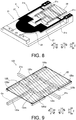
- the antireflection treatment is applied to portions of the pair of beams 21a, the torsion part 21c and the third beam 25c that do not overlap the mirror part 20, as well as to the surface of the driving source 22.
- the antireflection treatment includes, for example, a treatment of applying a black paint to the vicinity of the mirror part 20 and the surface of the driving source 22.
- the antireflection treatment may be applied by forming a black oxide film on the vicinity of the mirror part 20 and the surface of the driving source 22.
- the black oxide film is formed as the antireflection treatment, mechanical strength of the substrate 21 is able to be improved.
- the vibrating mirror element 2 includes: the mirror part 20 reflecting light; the substrate 21 made of metal and including: the pair of beams 21a each having the first end 121a and the second end 121b, the support 21b supporting the first end 121a of each of the pair of beams 21a, and the torsion part 21c swingably supporting the mirror part 20; the driving source 22 provided on the support 21b and generating the plate wave that swings the mirror part 20; and the vibration suppression part suppressing vibration transmitted to the pair of beams 21a by abutting against the pair of beams 21a.
- the torsion part 21c extends in the second direction orthogonal to the first direction in which the pair of beams 21a extends in the direction along the surface of the mirror part 20, and is connected to each of the pair of beams 21a.
- the vibration suppression part is configured to suppress the vibration transmitted to the pair of beams 21a by abutting against the pair of beams 21a at the position between the second mirror end 20b among the ends of the mirror part 20 that is opposite the first mirror end 20a near the support 21b and the torsion part 21c in the first direction.
- the first ends 121a of the pair of beams 21a are supported by the support 21b, unlike a configuration in which the mirror part 20 is arranged inside an opening provided in a frame-shaped substrate, even if the mirror part 20 is increased in size, the mirror part 20 is able to be prevented from abutting against the substrate 21 at the second end 121b side. Therefore, an increase in overall size of the vibrating mirror element 2 is able to be suppressed while the mirror part 20 is increased in size.
- the vibration suppression part that suppresses the vibration transmitted to the pair of beams 21a by abutting against the pair of beams 21a is provided at the position between the second mirror end 20b and the torsion part 21c, not only the vibration for swinging the mirror part 20 about the swing axis Ax but also the vibration in the direction (Z direction) orthogonal to the surface of the mirror part 20 is able to be prevented from being transmitted to the mirror part 20 via the torsion part 21c. Therefore, it is possible to prevent that the swing angle R of the mirror part 20 deviates from a predetermined swing angle range due to the vibration that causes the mirror part 20 to swing in the Z direction. As a result, even if the mirror part 20 is increased in size, the mirror part 20 is able to be stably swung while an increase in overall size of the vibrating mirror element 2 is suppressed.
- the holding member 24 that holds the support 21b and holds each of the pair of beams 21a is further provided.
- the holding member 24 is configured to hold each of the pair of beams 21a at the position where the vibration suppression part abuts against the pair of beams 21a or at the position nearer the second end 121b than the position where the vibration suppression part abuts against the pair of beams 21a. Accordingly, the substrate 21 is held by the holding member 24 at the support 21b and the second end 121b side of the pair of beams 21a.
- vibration of the substrate 21 itself is able to be suppressed.
- the mirror part 20 is able to be relatively stably swung.
- the vibration suppression part includes: the first vibration suppression part 23a, suppressing vibration by abutting against one of the pair of beams 21a; and the second vibration suppression part 23b, provided separately from the first vibration suppression part 23a and suppressing vibration by abutting against the other of the pair of beams 21a.
- Each of the first vibration suppression part 23a and the second vibration suppression part 23b is provided separately from the substrate 21 and the holding member 24.
- the holding member 24 has the carrying surface 24a carrying the first vibration suppression part 23a and the second vibration suppression part 23b.
- the carrying surface 24a is formed so as to extend in the first direction. Accordingly, positions of the first vibration suppression part 23a and the second vibration suppression part 23b are able to be individually adjusted.
- the mirror part 20 is able to be relatively stably swung.
- the mirror part 20 is configured so that the first distance D1 from the torsion part 21c to the second mirror end 20b in the first direction is equal to or greater than the second distance D2 from the torsion part 21c to the second end 121b in the first direction. Accordingly, the second ends 121b of the pair of beams 21a are able to be prevented from being arranged farther from the torsion part 21c than the second mirror end 20b. As a result, since it is possible to prevent the second end 121b from protruding more than the second mirror end 20b in the first direction (Y direction), an increase in the size of the vibrating mirror element 2 in the first direction is able to be suppressed while the mirror part 20 is increased in size.
- the vibration suppression part is configured so that the third distance D5 from the torsion part 21c to an end of the vibration suppression part near the second end 121b in the first direction is less than the first distance D1. Accordingly, the end of the vibration suppression part near the second end 121b is able to be prevented from being arranged farther from the torsion part 21c than the second mirror end 20b of the mirror part 20 in the first direction. As a result, an increase in the size of the vibrating mirror element 2 in the first direction is able to be suppressed.
- the mirror part 20 and the mirror part arrangement part 25 are joined at at least two places by the adhesive 26 having elasticity. Accordingly, for example, even if the mirror part 20 and the mirror part arrangement part 25 are made of different materials and have different linear expansion coefficients from each other, the occurrence of distortion in the mirror part 20 due to the difference in linear expansion coefficient between the mirror part 20 and the mirror part arrangement part 25 is able to be suppressed. As a result, it is possible to prevent that a scanning range of the light scanned by the mirror part 20 is different from a predetermined scanning range due to distortion of the mirror part 20.
- the adhesive 26 joins the mirror part 20 and the mirror part arrangement part 25 at least at two places at substantially equal distances from the center of gravity G of the mirror part 20 or the center of the surface of the mirror part 20. Accordingly, since the mirror part 20 and the mirror part arrangement part 25 are joined at positions at substantially equal distances from the center of gravity G of the mirror part 20 or from the center of the surface of the mirror part 20, weight unbalance after joining is able to be suppressed. As a result, when the mirror part 20 is swung, since it is possible to suppress the occurrence of unnecessary vibration due to weight unbalance between the mirror part 20 and the mirror part arrangement part 25, the mirror part 20 is able to be stably swung.
- the mirror part arrangement part 25 is thinned and formed into a beam shape so as to have a symmetrical mass on the reference plane Rp containing the center of gravity G of the mirror part 20 or the center of the surface of the mirror part 20. Accordingly, compared to a configuration in which the mirror part arrangement part 25 is not thinned and has a flat plate shape, the mirror part arrangement part 25 is able to be reduced in weight. In addition, since thinning is performed so that a symmetrical mass is achieved on the reference plane Rp containing the center of gravity G of the mirror part 20 or the center of the surface of the mirror part 20, weight unbalance of the mirror part arrangement part 25 after thinning is able to be suppressed. As a result, while the mirror part 20 is stably swung, electric power required to swing the mirror part 20 at the predetermined swing angle R is able to be reduced.
- the driving source 22 or the pair of beams 21a is provided with the weight member 27. Accordingly, if the weight member 27 is provided on the driving source 22, since it is possible to suppress unnecessary vibration, attenuation of the vibration applied from the driving source 22 is able to be suppressed. If the weight member 27 is provided on the pair of beams 21a, since it is possible to increase the vibration applied from the driving source 22, the swing angle R of the mirror part 20 is able to be easily increased.
- the treatment preventing reflection of the light reflected by the mirror part 20 is applied to at least one of the portion of the substrate 21 in the vicinity of the mirror part 20 and the surface of the driving source 22. Accordingly, it is possible to prevent the light irradiated to the mirror part 20 from being reflected by at least one of the substrate 21 in the vicinity of the mirror part 20 and the surface of the driving source 22. Therefore, the light reflected by a component other than the mirror part 20 is able to be prevented from becoming noise of scanning light.
- the optical scanner 100 includes: the light source 1 irradiating light; the mirror part 20 reflecting the light irradiated from the light source 1; the substrate 21 made of metal and including: the pair of beams 21a each having the first end 121a and the second end 121b, the support 21b supporting the first end 121a of each of the pair of beams 21a, and the torsion part 21c swingably supporting the mirror part 20; the driving source 22 provided on the support 21b and generating the plate wave that swings the mirror part 20; and the vibration suppression part suppressing vibration transmitted to the pair of beams 21a by abutting against the pair of beams 21a.
- the torsion part 21c extends in the second direction orthogonal to the first direction in which the pair of beams 21a extends in the direction along the surface of the mirror part 20, and is connected to each of the pair of beams 21a.
- the vibration suppression part is configured to suppress the vibration transmitted to the pair of beams 21a by abutting against the pair of beams 21a at the position between the second mirror end 20b among the ends of the mirror part 20 that is opposite the first mirror end 20a near the support 21b and the torsion part 21c in the first direction.
- the optical scanner 100 is able to be provided in which the mirror part 20 is able to be stably swung while an increase in overall size of the vibrating mirror element 2 is suppressed even if the mirror part 20 is increased in size.
- the torsion part 21c is connected with the mirror part arrangement part 25 at the position not overlapping the mirror part 20 in the second direction (X direction).
- the disclosure is not limited thereto.
- the torsion part 21c is provided so as to extend in the second direction (X direction) so as to overlap the mirror part 20, and is connected with a mirror part arrangement part 125 at a position overlapping the mirror part 20 in the second direction.
- the mirror part arrangement part 125 includes a pair of first beams 125a, a pair of second beams 125b, a pair of third beams 125c, a pair of fourth beams 125d, and a fifth beam 125e.
- Each of the pair of first beams 125a, the pair of third beams 125c and the pair of fourth beams 125d is arranged so as to extend in the first direction (Y direction).
- the pair of second beams 125b is arranged so as to extend in the second direction (X direction).
- An end of the pair of first beams 125a on the Y1 direction side is connected with the second beam 125b among the pair of second beams 125b that is provided on the Y2 direction side.
- the pair of third beams 125c is connected with each of the pair of second beams 125b.
- An end of the pair of fourth beams 125d on the Y2 direction side is connected with the second beam 125b provided on the Y1 direction side.
- the third beam 125c is arranged inside the mirror part 20 than the first beam 125a and the fourth beam 125d.
- the third beam 125c provided on the X1 direction side is provided nearer the X2 direction side than the first beam 125a and the fourth beam 125d provided on the X1 direction side, and is provided nearer the X1 direction side than a center line Cx passing through the center of the mirror part 20 in the second direction (X direction) and extending in the first direction (Y direction).
- the third beam 125c provided on the X2 direction side is provided nearer the X1 direction side than the first beam 125a and the fourth beam 125d provided on the X2 direction side, and is provided nearer the X2 direction side than the center line Cx.
- the fourth beam 125d is provided on the second beam 125b among the pair of second beams 125b that is provided on the Y1 direction side, and is arranged so as to extend in the first direction (Y direction).
- the torsion part 21c is connected to the pair of third beams 125c.
- the mirror part 20 is provided separately from the substrate 21.
- the substrate 21 further includes the mirror part arrangement part connected to the torsion part 21c and in which the mirror part 20 is arranged.
- the torsion part 21c is provided so as to extend in the second direction (X direction) so as to overlap the mirror part 20, and is connected with the mirror part arrangement part 125 at the position overlapping the mirror part 20 in the second direction.
- the torsion part 21c is connected with the mirror part arrangement part 125 at the position overlapping the mirror part 20 in the second direction, even if the length of the torsion part 21c in the second direction is increased in order to increase the swing angle R of the mirror part 20, an increase in the size of the substrate 21 in the second direction is able to be suppressed. As a result, an increase in the size of the vibrating mirror element 2 in the second direction is able to be suppressed.
- first vibration suppression part 23a and the second vibration suppression part 23b are separately provided.
- the disclosure is not limited thereto.
- the first vibration suppression part 23a and the second vibration suppression part 23b may be integrally formed with each other.
- a configuration example is shown in which the substrate 21 and the holding member 24 are separately provided.
- a substrate and a holding member may be integrally formed with each other.
- a holding part 21g may be formed by bending the holding part 21f.
- the holding part 21g has a frame-like shape.
- a holding part 21h may be formed by bending the holding part 21d.
- the holding part 21h has the carrying surface 24a carrying the first vibration suppression part 23a and the second vibration suppression part 23b.
- a weight member 127 may be provided in the vicinity of a driving source 322 as in a vibrating mirror element 302 according to a third modification shown in FIG. 11 .
- the driving source 322 has a triangular shape.
- the support 21b has the same shape as that in the above embodiments.
- a portion where the driving source 322 is not arranged is used as the weight member 127.
- a configuration example is shown in which the mirror part arrangement part 25 has the pair of first beams 25a, the pair of second beams 25b, and the third beam 25c.
- the disclosure is not limited thereto.
- a mirror part arrangement part 425 may have only a pair of first beams 425a.
- a configuration example is shown in which the mirror part 20 has a rectangular shape.
- the disclosure is not limited thereto.
- a mirror part 520 may have a shape other than the rectangular shape. Even if the mirror part 520 has a shape other than the rectangular shape, the same effects may be achieved if the mirror part 520 and a mirror part arrangement part 525 are joined at a position where their distances from the center of gravity G of the mirror part 520 are equal to each other.
- the mirror part 520 and the mirror part arrangement part 525 are joined at a ninth joining position P9 to a fifteenth joining position P15.
- a common sign is attached on broken lines connecting the adhesive 26 located at positions at equal distances from the center of gravity G of the mirror part 520 and the center of gravity G of the mirror part 520.
- the ninth joining position P9 and the twelfth joining position P12 that are attached with a fifth sign 40e are joining positions whose distances from the center of gravity G of the mirror part 520 are equal to each other.
- the eleventh joining position P11 and the fourteenth joining position P14 that are attached with a sixth sign 40f are joining positions whose distances from the center of gravity G of the mirror part 520 are equal to each other.
- the thirteenth joining position P13 and the fifteenth joining position P15 that are attached with a seventh sign 40g are joining positions whose distances from the center of gravity G of the mirror part 520 are equal to each other.
- the ninth joining position P9 and the tenth joining position P10 are attached with an eighth sign 40h since their distances from the reference plane Rp are equal to each other.
- the eleventh joining position P11 and the fourteenth joining position P14 are attached with the eighth sign 40h since their distances from the reference plane Rp are equal to each other.
- the vibration suppression part has the abutting surface 123a and is in surface contact with the beam 21a.
- the disclosure is not limited thereto.
- the vibration suppression part may be configured to be in point contact with the beam 21a. Even if the vibration suppression part is in point contact with the beam 21a, the same effects may be achieved if the position where the vibration suppression part contacts the beam 21a is set between the second mirror end 20b and the torsion part 21c.
- the vibration suppression part is configured separately from the substrate 21 and the holding member 24.
- the disclosure is not limited thereto.
- the vibration suppression part may be integrally formed with the substrate 21 or the holding member 24.
- the vibration suppression part is integrally formed with the substrate 21, by changing the size of the second end 121b side of the pair of beams 21a in the second direction (X direction), vibration is able to be suppressed.
- the holding part 21d in the above embodiments may be taken as the vibration suppression part.
- the vibration suppression part is integrally formed with the holding member 24, the same effects may be achieved if the end on the Y1 direction side of the portion for fixing the substrate 21 is taken as the vibration suppression part.
- the holding member 24 holds each of the pair of beams 21a at the position nearer the second end 121b than the position where the vibration suppression part abuts against the pair of beams 21a.
- the disclosure is not limited thereto.
- the holding member 24 may be configured to hold each of the pair of beams 21a at the position where the vibration suppression part abuts against the pair of beams 21a.
- the vibration suppression part includes the first vibration suppression part 23a and the second vibration suppression part 23b.
- the disclosure is not limited thereto.
- a single vibration suppression part may be configured to suppress vibration of the pair of beams 21a by abutting against both of the pair of beams 21a.
- the substrate 21 may be configured so that the second distance D2 is smaller than the first distance D1.
- the vibration suppression part may be configured so that the third distance D5 is equal to the first distance D1.
- the adhesive 26 joins the mirror part 20 and the mirror part arrangement part 25 at eight joining positions.
- the number of joints where the adhesive 26 joins the mirror part 20 and the mirror part arrangement part 25 may be any number equal to or greater than two.
- the adhesive 26 joins the mirror part 20 and the mirror part arrangement part 25 at the joining positions at substantially equal distances from the center of gravity G of the mirror part 20.
- the disclosure is not limited thereto.
- the adhesive 26 may join the mirror part 20 and the mirror part arrangement part 25 at the joining positions at substantially equal distances from the center of the surface of the mirror part 20.
- the mirror part arrangement part 25 is thinned so as to have a symmetrical mass on the reference plane Rp containing the center of gravity G of the mirror part 20.
- the disclosure is not limited thereto.
- the mirror part arrangement part 25 may be thinned so as to have a symmetrical mass on a reference plane containing the center of the surface of the mirror part 20.
- the weight member 27 is integrally formed with the substrate 21.
- the disclosure is not limited thereto.
- the weight member 27 may be configured separately from the substrate 21, and may be configured to be arranged on the substrate 21.
- the antireflection treatment is applied to the portion of the substrate 21 in the vicinity of the mirror part 20 and the surface of the driving source 22.
- the disclosure is not limited thereto.
- the antireflection treatment may be applied to neither the portion of the substrate 21 in the vicinity of the mirror part 20 nor the surface of the driving source 22.
- the antireflection treatment is preferably applied to at least one of the portion of the substrate 21 in the vicinity of the mirror part 20 and the surface of the driving source 22.
- the antireflection treatment is more preferably applied to the portion of the substrate 21 in the vicinity of the mirror part 20 and the surface of the driving source 22.
- the substrate 21 has a U-shape.
- the substrate 21 may have a shape other than the U-shape as long as the first ends 121a of the pair of beams 21a are supported by the support 21b.
Landscapes
- Physics & Mathematics (AREA)
- General Physics & Mathematics (AREA)
- Optics & Photonics (AREA)
- Engineering & Computer Science (AREA)
- Computer Hardware Design (AREA)
- Microelectronics & Electronic Packaging (AREA)
- Mechanical Light Control Or Optical Switches (AREA)
- Micromachines (AREA)
- Mechanical Optical Scanning Systems (AREA)
Abstract
Description
- The disclosure relates to a vibrating mirror element and an optical scanner.
- Conventionally, there are known a vibrating mirror element and an optical scanner (see, for example, Patent Document 1).
-
Patent Document 1 discloses an optical scanner including a substrate, a piezoelectric film, a twisted beam, and a mirror part. - The optical scanner disclosed in
Patent Document 1 is configured so that the mirror part supported by the twisted beam is swung by use of a plate wave excited in the substrate by the piezoelectric film. The substrate has a frame-like shape provided with an opening, and the mirror part is provided inside the opening via the twisted beam. In addition, one end of the substrate disclosed inPatent Document 1 is supported in a cantilevered manner by a support member. - [Patent Document 1] Japanese Patent Laid-open No.
2006-293116 - Here, although not specified in
Patent Document 1, as a scanner unit or the like including the vibrating mirror element is reduced in size, it is required that the vibrating mirror element be reduced in overall size after the size of the mirror part is increased. In addition, it is required that the mirror part be stably swung within a predetermined swing angle range in order to adapt to a use environment and a change in the use environment. However, in the case of attempting to increase the size of the mirror part arranged inside the substrate having a frame-like shape as in the optical scanner (vibrating mirror element) described inPatent Document 1, there is a problem that the substrate itself is also increased in size in order to avoid abutting against the mirror part. In addition, in the optical scanner (vibrating mirror element) described inPatent Document 1, since the substrate is supported in a cantilevered manner, not only vibration (plate wave) for swinging the mirror part about a swing axis but also vibration in a direction orthogonal to a surface of the mirror may be transmitted to the mirror part via the twisted beam (torsion part). In this case, there is a problem that it becomes difficult to stably swing the mirror part within the predetermined swing angle range. Therefore, there is a demand for a vibrating mirror element in which the mirror part is able to be stably swung while an increase in overall size of the vibrating mirror element is suppressed even if the mirror part is increased in size. - The disclosure provides a vibrating mirror element and an optical scanner in which the mirror part is able to be stably swung while an increase in overall size of the vibrating mirror element is suppressed even if the mirror part is increased in size.
- A vibrating mirror element according to a first aspect of the disclosure includes: a mirror part reflecting light; a substrate made of metal and including: a pair of beams each having a first end and a second end, a support supporting the first end of each of the pair of beams, and a torsion part swingably supporting the mirror part; a driving source provided on the support and generating a plate wave that swings the mirror part; and a vibration suppression part suppressing vibration transmitted to the pair of beams by abutting against the pair of beams. The torsion part extends in a second direction orthogonal to a first direction in which the pair of beams extends in a direction along a surface of the mirror part, and is connected to each of the pair of beams. The vibration suppression part is configured to suppress the vibration transmitted to the pair of beams by abutting against the pair of beams at a position between a second mirror end among ends of the mirror part that is opposite a first mirror end near the support and the torsion part in the first direction.
- As described above, the vibrating mirror element according to the first aspect of the disclosure includes the substrate made of metal and including the pair of beams, the support supporting the first ends of the pair of beams, and the torsion part swingably supporting the mirror part. Accordingly, since the first ends of the pair of beams are supported by the support, unlike a configuration in which the mirror part is arranged inside an opening provided in a frame-shaped substrate, even if the mirror part is increased in size, the mirror part is able to be prevented from abutting against the substrate at the second end side. Therefore, an increase in overall size of the vibrating mirror element is able to be suppressed while the mirror part is increased in size. In addition, since the vibration suppression part that suppresses the vibration transmitted to the pair of beams by abutting against the pair of beams is provided at the position between the second mirror end and the torsion part, not only the vibration for swinging the mirror part about the swing axis but also the vibration in the direction orthogonal to the surface of the mirror part is able to be prevented from being transmitted to the mirror part via the torsion part. Therefore, it is possible to prevent that a swing angle of the mirror part deviates from a predetermined swing angle range due to the vibration that causes the mirror part to swing in the direction orthogonal to the surface of the mirror part. As a result, even if the mirror part is increased in size, the mirror part is able to be stably swung while an increase in overall size of the vibrating mirror element is suppressed.
- In the vibrating mirror element according to the first aspect, preferably, a holding member is further included that holds the support and each of the pair of beams. The holding member is configured to hold each of the pair of beams at a position where the vibration suppression part abuts against the pair of beams or at a position nearer the second end than the position where the vibration suppression part abuts against the pair of beams. With such a configuration, the substrate is held by the holding member at the support and the second end side of the pair of beams. Thus, unlike a configuration in which the substrate is held in a cantilever state by a support member, vibration of the substrate itself is able to be suppressed. As a result, since it is possible to suppress movement of a center position of swinging of the mirror part caused by vibration of the substrate itself, the mirror part is able to be relatively stably swung.
- In this case, preferably, the vibration suppression part includes: a first vibration suppression part suppressing vibration by abutting against one of the pair of beams, and a second vibration suppression part provided separately from the first vibration suppression part and suppressing vibration by abutting against the other of the pair of beams. Each of the first vibration suppression part and the second vibration suppression part is provided separately from the substrate and the holding member. The holding member has a carrying surface carrying the first vibration suppression part and the second vibration suppression part. The carrying surface is formed so as to extend in the first direction. With such a configuration, positions of the first vibration suppression part and the second vibration suppression part are able to be individually adjusted. As a result, in one of the pair of beams and the other of the pair of beams, since it is possible to individually arrange the first vibration suppression part and the second vibration suppression part at positions where unnecessary vibration is able to be suppressed, the mirror part is able to be relatively stably swung.
- In the vibrating mirror element according to the first aspect, preferably, the mirror part is configured so that a first distance from the torsion part to the second mirror end in the first direction is equal to or greater than a second distance from the torsion part to the second end in the first direction. With such a configuration, the second ends of the pair of beams are able to be prevented from being arranged farther from the torsion part than the second mirror end. As a result, since it is possible to prevent the second end from protruding more than the second mirror end in the first direction, an increase in the size of the vibrating mirror element in the first direction is able to be suppressed while the mirror part is increased in size.
- In this case, preferably, the vibration suppression part is configured so that a third distance from the torsion part to an end of the vibration suppression part near the second end in the first direction is less than the first distance. With such a configuration, the end of the vibration suppression part near the second mirror end is able to be prevented from being arranged farther from the torsion part than the second end of the mirror part in the first direction. As a result, an increase in the size of the vibrating mirror element in the first direction is able to be suppressed.
- In the vibrating mirror element according to the first aspect, preferably, the mirror part is provided separately from the substrate. The substrate further includes a mirror part arrangement part connected to the torsion part, the mirror part being arranged in the mirror part arrangement part. The torsion part is provided so as to extend in the second direction so as to overlap the mirror part, and is connected with the mirror part arrangement part at a position overlapping the mirror part in the second direction. With such a configuration, since the torsion part is connected with the mirror part arrangement part at the position overlapping the mirror part in the second direction, even if the length of the torsion part in the second direction is increased in order to increase the swing angle of the mirror part, an increase in the size of the substrate in the second direction is able to be suppressed. As a result, an increase in the size of the vibrating mirror element in the second direction is able to be suppressed.
- In this case, preferably, the mirror part and the mirror part arrangement part are joined at at least two places by an adhesive having elasticity. With such a configuration, for example, even if the mirror part and the mirror part arrangement part are made of different materials and have different linear expansion coefficients from each other, the occurrence of distortion in the mirror part due to the difference in linear expansion coefficient between the mirror part and the mirror part arrangement part is able to be suppressed. As a result, it is possible to prevent that a scanning range of the light scanned by the mirror part is different from a predetermined scanning range due to distortion of the mirror part.
- In the configuration in which the mirror part and the mirror part arrangement part are joined at at least two places by the adhesive having elasticity, preferably, the adhesive joins the mirror part and the mirror part arrangement part at least at two places at substantially equal distances from a center of gravity of the mirror part or from a center of a surface of the mirror part. With such a configuration, since the mirror part and the mirror part arrangement part are joined at positions at substantially equal distances from the center of gravity of the mirror part or from the center of the surface of the mirror part, weight unbalance after joining is able to be suppressed. As a result, when the mirror part is swung, since it is possible to suppress the occurrence of unnecessary vibration due to weight unbalance between the mirror part and the mirror part arrangement part, the mirror part is able to be stably swung.
- In the configuration in which the torsion part is connected with the mirror part arrangement part at the position overlapping the mirror part in the second direction, preferably, the mirror part arrangement part is thinned and formed into a beam shape so as to have a symmetrical mass on a reference plane containing the center of gravity of the mirror part or the center of the surface of the mirror part. With such a configuration, compared to a configuration in which the mirror part arrangement part is not thinned and has a flat plate shape, the mirror part arrangement part is able to be reduced in weight. In addition, since thinning is performed so that a symmetrical mass is achieved on the reference plane containing the center of gravity of the mirror part or the center of the surface of the mirror part, weight unbalance of the mirror part arrangement part after thinning is able to be suppressed. As a result, while the mirror part is stably swung, electric power required to swing the mirror part at a predetermined swing angle is able to be reduced.
- In the vibrating mirror element according to the first aspect, preferably, a weight member is provided on the driving source or the pair of beams. With such a configuration, if the weight member is provided on the driving source, since it is possible to suppress unnecessary vibration, attenuation of the vibration applied from the driving source is able to be suppressed. If the weight member is provided on the pair of beams, since it is possible to increase the vibration applied from the driving source, the swing angle of the mirror part is able to be easily increased.
- In the vibrating mirror element according to the first aspect, preferably, a treatment preventing reflection of the light reflected by the mirror part is applied to at least one of a portion of the substrate in the vicinity of the mirror part and a surface of the driving source. With such a configuration, it is possible to prevent the light irradiated to the mirror part from being reflected by at least one of the substrate in the vicinity of the mirror part and the surface of the driving source. Therefore, the light reflected by a component other than the mirror part is able to be prevented from becoming noise of scanning light.
- An optical scanner according to a second aspect of the disclosure includes: a light source irradiating light; a mirror part reflecting the light irradiated from the light source; a substrate made of metal and including: a pair of beams each having a first end and a second end, a support supporting the first end of each of the pair of beams, and a torsion part swingably supporting the mirror part; a driving source provided on the support and generating a plate wave that swings the mirror part; and a vibration suppression part suppressing vibration transmitted to the pair of beams by abutting against the pair of beams. The torsion part extends in a second direction orthogonal to a first direction in which the pair of beams extends in a direction along a surface of the mirror part, and is connected to each of the pair of beams. The vibration suppression part is configured to suppress the vibration transmitted to the pair of beams by abutting against the pair of beams at a position between a second mirror end among ends of the mirror part that is opposite a first mirror end near the support and the torsion part in the first direction.
- As described above, the optical scanner according to the second aspect of the disclosure includes the substrate made of metal and including the pair of beams, the support supporting the first ends of the pair of beams, and the torsion part swingably supporting the mirror part, as well as the vibration suppression part configured to suppress the vibration transmitted to the pair of beams by abutting against the pair of beams at the position between the second mirror end and the torsion part. Accordingly, like the vibrating mirror element of the first aspect, even if the mirror part is increased in size, the mirror part is able to be stably swung while an increase in overall size of the vibrating mirror element is suppressed.
- As described above, according to the disclosure, the vibrating mirror element and the optical scanner are able to be provided in which the mirror part is able to be stably swung while an increase in overall size of the vibrating mirror element is suppressed even if the mirror part is increased in size.
-
-
FIG. 1 is a block diagram showing an overall configuration of an optical scanner according to one embodiment. -
FIG. 2 is a perspective view of a vibrating mirror element according to one embodiment. -
FIG. 3 is a plan view of a vibrating mirror element according to one embodiment. -
FIG. 4 is a schematic view of a vibrating mirror element as viewed from a direction in which a swing axis extends according to one embodiment. -
FIG. 5 is a schematic view for describing a position where a position where a vibration suppression part abuts against a pair of beams according to one embodiment. -
FIG. 6 is a perspective view for describing a position where a mirror part and a mirror part arrangement part are joined according to one embodiment. -
FIG. 7 is a perspective view for describing a structure of a mirror part arrangement part according to one embodiment. -
FIG. 8 is a perspective view for describing an antireflection treatment applied to a substrate according to one embodiment. -
FIG. 9 is a perspective view for describing a configuration of a mirror part arrangement part according to a first modification. -
FIG. 10 is a perspective view for describing a configuration of a vibrating mirror element according to a second modification. -
FIG. 11 is a perspective view for describing a configuration of a vibrating mirror element according to a third modification. -
FIG. 12 is a perspective view for describing a configuration of a mirror part arrangement part according to a fourth modification. -
FIG. 13 is a perspective view for describing a configuration of a mirror part and a mirror part arrangement part according to a fifth modification. - Hereinafter, embodiments of the disclosure will be described with reference to the drawings.
- Referring to
FIG. 1 to FIG. 8 , a configuration of a vibratingmirror element 2 and a configuration of anoptical scanner 100 including the vibratingmirror element 2 according to one embodiment are described. - As shown in
FIG. 1 , theoptical scanner 100 according to the present embodiment includes alight source 1, a vibratingmirror element 2, and acontrol part 3. Theoptical scanner 100 is configured to irradiate aprojection plane 60 with light. - The
light source 1 is configured to output light. Specifically, thelight source 1 is configured to irradiate, via a lens or the like, amirror part 20 included in the vibratingmirror element 2. Thelight source 1 includes, for example, a light emitting diode (LED) or a laser diode (LD). - The vibrating
mirror element 2 is configured so that the light irradiated from thelight source 1 is reflected by themirror part 20 so as to be projected onto theprojection plane 60 while themirror part 20 is swung by a plate wave generated by a drivingsource 22. A detailed configuration of the vibratingmirror element 2 will be described later. - The
control part 3 is configured to control irradiation of laser light by thelight source 1. Specifically, thecontrol part 3 is configured to control the timing of each of blue laser light, red laser light, and green laser light irradiated from thelight source 1. - The
control part 3 is configured to control each part of theoptical scanner 100. Thecontrol part 3 is configured to acquire from the outside a video signal to be projected onto theprojection plane 60. Thecontrol part 3 is configured to control the irradiation of laser light by thelight source 1 based on the acquired video signal. Thecontrol part 3 includes, for example, a processor such as a central processing unit (CPU). - As shown in
FIG. 2 , the vibratingmirror element 2 includes themirror part 20, asubstrate 21, the drivingsource 22, a vibration suppression part, and a holdingmember 24. In the present specification, a direction orthogonal to a surface of themirror part 20 is taken as a Z direction, an upward direction is taken as a Z1 direction, and a downward direction is taken as a Z2 direction. Two directions orthogonal to each other in a plane orthogonal to the Z direction are taken as an X direction and a Y direction, respectively. One side of the X direction is taken as an X1 direction and the other side thereof is taken as an X2 direction. One side of the Y direction is taken as a Y1 direction and the other side thereof is taken as a Y2 direction. - The
mirror part 20 is configured to reflect the light irradiated from thelight source 1. Themirror part 20 has a rectangular shape. In addition, themirror part 20 is made of, for example, an aluminum material. In the present embodiment, themirror part 20 is provided separately from thesubstrate 21. Specifically, themirror part 20 is provided in a mirrorpart arrangement part 25. In the example shown inFIG. 2 , themirror part 20 is shown with hatching for convenience. - The
substrate 21 includes a pair ofbeams 21a, asupport 21b, and atorsion part 21c. In addition, thesubstrate 21 includes the mirrorpart arrangement part 25 in which themirror part 20 is arranged. Thesubstrate 21 is made of, for example, a stainless steel material having a flat plate shape. - The pair of
beams 21a each have afirst end 121a and asecond end 121b. Each of thefirst ends 121a is supported by thesupport 21b. In the present embodiment, the pair ofbeams 21a is supported by thesupport 21b via aweight member 27. That is, thefirst end 121a is a portion connected with theweight member 27. Thesecond end 121b is an end of the pair ofbeams 21a that is not connected to theweight member 27 in a first direction (Y direction). In the example shown inFIG. 2 , a holdingpart 21d held by the holdingmember 24 is provided on thesecond end 121b side of the pair ofbeams 21a. The holdingpart 21d is a portion of the pair ofbeams 21a. - In the example shown in
FIG. 2 , the holdingpart 21d is formed by increasing a width of thesecond end 121b side of the pair ofbeams 21a in the X direction. The holdingpart 21d is held by the holdingmember 24, for example, by being screwed thereto. Hence, the holdingpart 21d is provided with a throughhole 30 penetrating in the Z direction. - The
support 21b is configured to support thefirst end 121a of each of the pair ofbeams 21a. Thesupport 21b is provided with the drivingsource 22. Specifically, thesupport 21b includes a drivingsource support 21e that supports the drivingsource 22, and the drivingsource 22 is arranged in the drivingsource support 21e. The drivingsource support 21e has a semicircular shape, like the drivingsource 22. Thesupport 21b includes a holdingpart 21f at an end on the side that does not support the pair ofbeams 21a in the first direction (Y direction). Thesupport 21b is held by the holdingmember 24, for example, by being screwed thereto. Hence, the holdingpart 21f is provided with a throughhole 31 penetrating in the Z direction. - The
torsion part 21c swingably supports themirror part 20. Thetorsion part 21c extends in a second direction (X direction) orthogonal to the first direction (Y direction) in which the pair ofbeams 21a extends in a direction along the surface of themirror part 20. Thetorsion part 21c has a columnar shape. Thetorsion part 21c is provided as a pair. One of the pair oftorsion parts 21c is connected with one of the pair ofbeams 21a, and theother torsion part 21c is connected to theother beam 21a. Each of the pair oftorsion parts 21c is connected to the mirrorpart arrangement part 25. - The mirror
part arrangement part 25 is configured so that themirror part 20 is arranged therein. The mirrorpart arrangement part 25 is connected to the pair ofbeams 21a via thetorsion part 21c. A detailed configuration of the mirrorpart arrangement part 25 will be described later. - The driving
source 22 is configured to generate the plate wave that swings themirror part 20. The drivingsource 22 includes, for example, a piezoelectric element. The piezoelectric element includes, for example, lead zirconate titanate (PZT). In the example shown inFIG. 2 , PZT having a semicircular shape is provided as the drivingsource 22 on thesubstrate 21. - The vibration suppression part is configured to suppress vibration transmitted to the pair of
beams 21a by abutting against the pair ofbeams 21a. The vibration suppression part includes: a firstvibration suppression part 23a, suppressing vibration by abutting against one of the pair ofbeams 21a; and a secondvibration suppression part 23b, provided separately from the firstvibration suppression part 23a and suppressing vibration by abutting against the other of the pair ofbeams 21a. Each of the firstvibration suppression part 23a and the secondvibration suppression part 23b is provided separately from thesubstrate 21 and the holdingmember 24. Each of the firstvibration suppression part 23a and the secondvibration suppression part 23b has anabutting surface 123a (seeFIG. 5 ) abutting against thebeam 21a. Details of positions where the firstvibration suppression part 23a and the secondvibration suppression part 23b abut against the pair ofbeams 21a or the like will be described later. - The holding
member 24 is configured to hold thesupport 21b. As shown inFIG. 2 , the holdingmember 24 holds the holdingpart 21f provided at the end of thesupport 21b on the side that does not support the pair ofbeams 21a in the first direction (Y direction). The holdingmember 24 is configured to hold each of the pair ofbeams 21a. As shown inFIG. 2 , the holdingmember 24 is configured to hold the holdingpart 21d of the pair ofbeams 21a. - As shown in
FIG. 2 , the holdingmember 24 is configured to hold each of the pair ofbeams 21a at a position where the vibration suppression part abuts against the pair ofbeams 21a or at a position nearer thesecond end 121b than the position where the vibration suppression part abuts against the pair ofbeams 21a. In the example shown inFIG. 2 , the holdingmember 24 holds each of the pair ofbeams 21a at the position nearer thesecond end 121b than the position where the vibration suppression part abuts against the pair ofbeams 21a. - The holding
member 24 has a carryingsurface 24a carrying the firstvibration suppression part 23a and the secondvibration suppression part 23b. The carryingsurface 24a is formed so as to extend in the first direction (Y direction). The carryingsurface 24a is portion of a surface of the holdingmember 24 on the Z1 direction side, extending in a direction (Y direction) in which the pair ofbeams 21a extends below (Z2 direction side) the pair ofbeams 21a. - As shown in
FIG. 3 , in thesubstrate 21, the pair ofbeams 21a is supported by thesupport 21b. Therefore, in the present embodiment, thesubstrate 21 has a U-shape in plan view. Although not shown inFIG. 3 , the holdingmember 24 also has a U-shape, like thesubstrate 21. - The driving
source 22 or the pair ofbeams 21a is provided with theweight member 27. As shown inFIG. 3 , in the present embodiment, theweight member 27 is provided integrally with thesubstrate 21 on thefirst end 121a side of the pair ofbeams 21a. Specifically, theweight member 27 is integrally provided on thesubstrate 21 by increasing the size of thefirst end 121a side in the X direction. - In the present embodiment, as shown in
FIG. 3 , themirror part 20 is configured so that a first distance D1 from thetorsion part 21c to asecond mirror end 20b in the first direction (Y direction) is equal to or greater than a second distance D2 from thetorsion part 21c to thesecond end 121b in the first direction. In the present embodiment, a length from the center of thetorsion part 21c to thesecond mirror end 20b in the Y direction is taken as the first distance D1. A length from the center of thetorsion part 21c to thesecond end 121b in the Y direction is taken as the second distance D2. - The
torsion part 21c is connected to the mirrorpart arrangement part 25 at a position not overlapping themirror part 20 in the second direction (X direction). Specifically, thetorsion part 21c is connected to the mirrorpart arrangement part 25 at a position where a distance D3 from thebeam 21a to anend 20c of themirror part 20 in the X direction is equal to a length D4 of thetorsion part 21c in the X direction. - As shown in
FIG. 4 , themirror part 20 is swung about a swing axis Ax so as to have a predetermined swing angle R. In the present embodiment, themirror part 20 is swung about the swing axis Ax by the plate wave generated by the drivingsource 22. Specifically, by expansion and contraction of the drivingsource 22 in a direction (direction parallel to an XY plane) parallel to a surface of thesubstrate 21, thesubstrate 21 is bent in the Z direction, thereby generating the plate wave. The plate wave generated by the drivingsource 22 is transmitted to thetorsion part 21c via the pair ofbeams 21a. Thetorsion part 21c swings the mirrorpart arrangement part 25 by being twisted by the plate wave transmitted via the pair ofbeams 21a. The mirrorpart arrangement part 25 swings themirror part 20 by being swung by thetorsion part 21c. Thetorsion part 21c is arranged so as to be at a position corresponding to an antinode portion or a node portion of the plate wave generated by the drivingsource 22. The plate wave includes a symmetric plate wave and an asymmetric plate wave. In the case of the symmetric plate wave, a maximum point of amplitude is the antinode portion and a minimum point of amplitude is the node portion. In the case of the asymmetric plate wave, a portion where displacement becomes maximum is the antinode portion, and a portion where displacement becomes minimum is the node portion. - As shown in
FIG. 4 , themirror part 20 and the mirrorpart arrangement part 25 are joined at at least two places by an adhesive 26 having elasticity. Since themirror part 20 and the mirrorpart arrangement part 25 are joined by the adhesive 26 having elasticity, they are joined with a slight gap therebetween in the Z direction, as shown inFIG. 4 . Accordingly, when thetorsion part 21c is twisted, it is possible to prevent thetorsion part 21c from abutting against themirror part 20, and themirror part 20 is able to be stably swung at the predetermined swing angle R.FIG. 4 does not show a cross section, and hatches are added to make it easy to identify themirror part 20, thetorsion part 21c, the mirrorpart arrangement part 25, and the adhesive 26. - Next, referring to
FIG. 5 , the position where the vibration suppression part abuts against the pair ofbeams 21a will be described. The vibration suppression part is configured to suppress the vibration transmitted to the pair ofbeams 21a by abutting against the pair ofbeams 21a at a position between thesecond mirror end 20b among the ends of themirror part 20 that is opposite afirst mirror end 20a near thesupport 21b and thetorsion part 21c in the first direction (Y direction). Specifically, the vibration suppression part is configured to suppress transmission of the vibration that swings thesubstrate 21 in the Z direction to the pair ofbeams 21a. - As shown in
FIG. 5 , the firstvibration suppression part 23a abuts against the beam on the X2 direction side among the pair ofbeams 21a from the Z2 direction side. At this time, the position of the firstvibration suppression part 23a in the first direction (Y direction) is adjusted so that, in theabutting surface 123a of the firstvibration suppression part 23a abutting against the beam, an abuttingportion 123b of an end on the Y1 direction side is located between thesecond mirror end 20b and thetorsion part 21c. The position of the abuttingportion 123b is determined by the size of themirror part 20, the thickness and length of thetorsion part 21c, and the like. Although not shown inFIG. 5 , the secondvibration suppression part 23b abuts against the beam on the X1 direction side among the pair ofbeams 21a. The position of the secondvibration suppression part 23b is adjusted in the same manner as the firstvibration suppression part 23a. In other words, the firstvibration suppression part 23a and the secondvibration suppression part 23b are configured to suppress the occurrence of an unwanted vibration mode or suppress the intensity by adjusting a length (length from the abuttingportion 123b to thefirst end 121a) of a vibrating portion of the pair ofbeams 21a. - The first
vibration suppression part 23a is configured so that a third distance D5 from thetorsion part 21c to an end of the firstvibration suppression part 23a near thesecond end 121b in the first direction (Y direction) is less than the first distance D1. In the present embodiment, a length from the center of thetorsion part 21c to the end of the firstvibration suppression part 23a near thesecond end 121b in the Y direction is taken as the third distance D5. Although not shown inFIG. 5 , in the secondvibration suppression part 23b, a distance from thetorsion part 21c to an end of the secondvibration suppression part 23b near thesecond end 121b in the first direction (Y direction) is configured to be less than the first distance D1. - Next, referring to
FIG. 6 , a position where themirror part 20 and the mirrorpart arrangement part 25 are joined by the adhesive 26 will be described. - The adhesive 26 joins the
mirror part 20 and the mirrorpart arrangement part 25 at least at two places at substantially equal distances from the center of gravity G of themirror part 20 or the center of the surface of themirror part 20. In the example shown inFIG. 6 , the adhesive 26 joins themirror part 20 and the mirrorpart arrangement part 25 at eight places at substantially equal distances from the center of gravity G of themirror part 20. Specifically, the adhesive 26 joins themirror part 20 and the mirrorpart arrangement part 25 at eight places, i.e., a first joining position P1 to an eighth joining position P8. - In the example shown in
FIG. 6 , with respect to the adhesive 26 at the joining positions whose distances from the center of gravity G of themirror part 20 are equal to each other, a common sign is attached on broken lines connecting arrangement positions of the adhesive 26 and the center of gravity G of themirror part 20. That is, the first joining position P1 and the eighth joining position P8 that are attached with afirst sign 40a are joining positions whose distances from the center of gravity G of themirror part 20 are equal to each other. The second joining position P2 and the seventh joining position P7 that are attached with asecond sign 40b are joining positions whose distances from the center of gravity G of themirror part 20 are equal to each other. The third joining position P3 and the sixth joining position P6 that are attached with athird sign 40c are joining positions whose distances from the center of gravity G of themirror part 20 are equal to each other. The fourth joining position P4 and the fifth joining position P5 that are attached with afourth sign 40d are joining positions whose distances from the center of gravity G of themirror part 20 are equal to each other. - As shown in
FIG. 7 , the mirrorpart arrangement part 25 is thinned and formed into a beam shape so as to have a symmetrical mass on a reference plane Rp containing the center of gravity G of themirror part 20 or the center of the surface of themirror part 20. In the example shown inFIG. 7 , the reference plane Rp is a YZ plane. In the example shown inFIG. 7 , the mirrorpart arrangement part 25 is thinned and formed into a beam shape so as to have a symmetrical mass on the reference plane Rp containing the center of gravity G of themirror part 20. That is, the mirrorpart arrangement part 25 is thinned and formed into a beam shape so that the mass on the X1 direction side of the reference plane Rp and the mass on the X2 direction side of the reference plane Rp are equal to each other. - Specifically, the mirror
part arrangement part 25 includes a pair offirst beams 25a, a pair ofsecond beams 25b, and athird beam 25c. The pair offirst beams 25a is arranged so as to extend in the first direction (Y direction). The pair ofsecond beams 25b is arranged so as to extend in the second direction (X direction). Thethird beam 25c is provided on thesecond beam 25b among the pair ofsecond beams 25b that is provided on the Y1 direction side, and is arranged so as to extend in the first direction (Y direction). Thetorsion part 21c is connected to the pair offirst beams 25a at the position not overlapping themirror part 20 in the second direction (X direction). - As shown in
FIG. 8 , a treatment preventing reflection of the light reflected by themirror part 20 is applied to at least one of a portion of thesubstrate 21 in the vicinity of themirror part 20 and a surface of the drivingsource 22. In the example shown inFIG. 8 , an antireflection treatment is applied to both the vicinity of themirror part 20 and the surface of the drivingsource 22. Specifically, in the present embodiment, in thesubstrate 21, the antireflection treatment is applied to portions of the pair ofbeams 21a, thetorsion part 21c and thethird beam 25c that do not overlap themirror part 20, as well as to the surface of the drivingsource 22. - The antireflection treatment includes, for example, a treatment of applying a black paint to the vicinity of the
mirror part 20 and the surface of the drivingsource 22. For example, the antireflection treatment may be applied by forming a black oxide film on the vicinity of themirror part 20 and the surface of the drivingsource 22. In the case where the black oxide film is formed as the antireflection treatment, mechanical strength of thesubstrate 21 is able to be improved. - In the present embodiment, the following effects are able to be achieved.
- As described above, in the present embodiment, the vibrating
mirror element 2 includes: themirror part 20 reflecting light; thesubstrate 21 made of metal and including: the pair ofbeams 21a each having thefirst end 121a and thesecond end 121b, thesupport 21b supporting thefirst end 121a of each of the pair ofbeams 21a, and thetorsion part 21c swingably supporting themirror part 20; the drivingsource 22 provided on thesupport 21b and generating the plate wave that swings themirror part 20; and the vibration suppression part suppressing vibration transmitted to the pair ofbeams 21a by abutting against the pair ofbeams 21a. Thetorsion part 21c extends in the second direction orthogonal to the first direction in which the pair ofbeams 21a extends in the direction along the surface of themirror part 20, and is connected to each of the pair ofbeams 21a. The vibration suppression part is configured to suppress the vibration transmitted to the pair ofbeams 21a by abutting against the pair ofbeams 21a at the position between thesecond mirror end 20b among the ends of themirror part 20 that is opposite thefirst mirror end 20a near thesupport 21b and thetorsion part 21c in the first direction. - Accordingly, since the first ends 121a of the pair of
beams 21a are supported by thesupport 21b, unlike a configuration in which themirror part 20 is arranged inside an opening provided in a frame-shaped substrate, even if themirror part 20 is increased in size, themirror part 20 is able to be prevented from abutting against thesubstrate 21 at thesecond end 121b side. Therefore, an increase in overall size of the vibratingmirror element 2 is able to be suppressed while themirror part 20 is increased in size. In addition, since the vibration suppression part that suppresses the vibration transmitted to the pair ofbeams 21a by abutting against the pair ofbeams 21a is provided at the position between thesecond mirror end 20b and thetorsion part 21c, not only the vibration for swinging themirror part 20 about the swing axis Ax but also the vibration in the direction (Z direction) orthogonal to the surface of themirror part 20 is able to be prevented from being transmitted to themirror part 20 via thetorsion part 21c. Therefore, it is possible to prevent that the swing angle R of themirror part 20 deviates from a predetermined swing angle range due to the vibration that causes themirror part 20 to swing in the Z direction. As a result, even if themirror part 20 is increased in size, themirror part 20 is able to be stably swung while an increase in overall size of the vibratingmirror element 2 is suppressed. - As described above, in the present embodiment, the holding
member 24 that holds thesupport 21b and holds each of the pair ofbeams 21a is further provided. The holdingmember 24 is configured to hold each of the pair ofbeams 21a at the position where the vibration suppression part abuts against the pair ofbeams 21a or at the position nearer thesecond end 121b than the position where the vibration suppression part abuts against the pair ofbeams 21a. Accordingly, thesubstrate 21 is held by the holdingmember 24 at thesupport 21b and thesecond end 121b side of the pair ofbeams 21a. Thus, unlike a configuration in which thesubstrate 21 is held in a cantilever state by a support member, vibration of thesubstrate 21 itself is able to be suppressed. As a result, since it is possible to suppress movement of a center position of swinging of themirror part 20 caused by vibration of thesubstrate 21 itself, themirror part 20 is able to be relatively stably swung. - As described above, in the present embodiment, the vibration suppression part includes: the first
vibration suppression part 23a, suppressing vibration by abutting against one of the pair ofbeams 21a; and the secondvibration suppression part 23b, provided separately from the firstvibration suppression part 23a and suppressing vibration by abutting against the other of the pair ofbeams 21a. Each of the firstvibration suppression part 23a and the secondvibration suppression part 23b is provided separately from thesubstrate 21 and the holdingmember 24. The holdingmember 24 has the carryingsurface 24a carrying the firstvibration suppression part 23a and the secondvibration suppression part 23b. The carryingsurface 24a is formed so as to extend in the first direction. Accordingly, positions of the firstvibration suppression part 23a and the secondvibration suppression part 23b are able to be individually adjusted. As a result, in one of the pair ofbeams 21a and the other of the pair ofbeams 21a, since it is possible to individually arrange the firstvibration suppression part 23a and the secondvibration suppression part 23b at positions where unnecessary vibration is able to be suppressed, themirror part 20 is able to be relatively stably swung. - As described above, in the present embodiment, the
mirror part 20 is configured so that the first distance D1 from thetorsion part 21c to thesecond mirror end 20b in the first direction is equal to or greater than the second distance D2 from thetorsion part 21c to thesecond end 121b in the first direction. Accordingly, the second ends 121b of the pair ofbeams 21a are able to be prevented from being arranged farther from thetorsion part 21c than thesecond mirror end 20b. As a result, since it is possible to prevent thesecond end 121b from protruding more than thesecond mirror end 20b in the first direction (Y direction), an increase in the size of the vibratingmirror element 2 in the first direction is able to be suppressed while themirror part 20 is increased in size. - As described above, in the present embodiment, the vibration suppression part is configured so that the third distance D5 from the
torsion part 21c to an end of the vibration suppression part near thesecond end 121b in the first direction is less than the first distance D1. Accordingly, the end of the vibration suppression part near thesecond end 121b is able to be prevented from being arranged farther from thetorsion part 21c than thesecond mirror end 20b of themirror part 20 in the first direction. As a result, an increase in the size of the vibratingmirror element 2 in the first direction is able to be suppressed. - As described above, in the present embodiment, the
mirror part 20 and the mirrorpart arrangement part 25 are joined at at least two places by the adhesive 26 having elasticity. Accordingly, for example, even if themirror part 20 and the mirrorpart arrangement part 25 are made of different materials and have different linear expansion coefficients from each other, the occurrence of distortion in themirror part 20 due to the difference in linear expansion coefficient between themirror part 20 and the mirrorpart arrangement part 25 is able to be suppressed. As a result, it is possible to prevent that a scanning range of the light scanned by themirror part 20 is different from a predetermined scanning range due to distortion of themirror part 20. - As described above, in the present embodiment, the adhesive 26 joins the
mirror part 20 and the mirrorpart arrangement part 25 at least at two places at substantially equal distances from the center of gravity G of themirror part 20 or the center of the surface of themirror part 20. Accordingly, since themirror part 20 and the mirrorpart arrangement part 25 are joined at positions at substantially equal distances from the center of gravity G of themirror part 20 or from the center of the surface of themirror part 20, weight unbalance after joining is able to be suppressed. As a result, when themirror part 20 is swung, since it is possible to suppress the occurrence of unnecessary vibration due to weight unbalance between themirror part 20 and the mirrorpart arrangement part 25, themirror part 20 is able to be stably swung. - As described above, in the present embodiment, the mirror
part arrangement part 25 is thinned and formed into a beam shape so as to have a symmetrical mass on the reference plane Rp containing the center of gravity G of themirror part 20 or the center of the surface of themirror part 20. Accordingly, compared to a configuration in which the mirrorpart arrangement part 25 is not thinned and has a flat plate shape, the mirrorpart arrangement part 25 is able to be reduced in weight. In addition, since thinning is performed so that a symmetrical mass is achieved on the reference plane Rp containing the center of gravity G of themirror part 20 or the center of the surface of themirror part 20, weight unbalance of the mirrorpart arrangement part 25 after thinning is able to be suppressed. As a result, while themirror part 20 is stably swung, electric power required to swing themirror part 20 at the predetermined swing angle R is able to be reduced. - As described above, in the present embodiment, the driving
source 22 or the pair ofbeams 21a is provided with theweight member 27. Accordingly, if theweight member 27 is provided on the drivingsource 22, since it is possible to suppress unnecessary vibration, attenuation of the vibration applied from the drivingsource 22 is able to be suppressed. If theweight member 27 is provided on the pair ofbeams 21a, since it is possible to increase the vibration applied from the drivingsource 22, the swing angle R of themirror part 20 is able to be easily increased. - As described above, in the present embodiment, the treatment preventing reflection of the light reflected by the
mirror part 20 is applied to at least one of the portion of thesubstrate 21 in the vicinity of themirror part 20 and the surface of the drivingsource 22. Accordingly, it is possible to prevent the light irradiated to themirror part 20 from being reflected by at least one of thesubstrate 21 in the vicinity of themirror part 20 and the surface of the drivingsource 22. Therefore, the light reflected by a component other than themirror part 20 is able to be prevented from becoming noise of scanning light. - As described above, in the present embodiment, the
optical scanner 100 includes: thelight source 1 irradiating light; themirror part 20 reflecting the light irradiated from thelight source 1; thesubstrate 21 made of metal and including: the pair ofbeams 21a each having thefirst end 121a and thesecond end 121b, thesupport 21b supporting thefirst end 121a of each of the pair ofbeams 21a, and thetorsion part 21c swingably supporting themirror part 20; the drivingsource 22 provided on thesupport 21b and generating the plate wave that swings themirror part 20; and the vibration suppression part suppressing vibration transmitted to the pair ofbeams 21a by abutting against the pair ofbeams 21a. Thetorsion part 21c extends in the second direction orthogonal to the first direction in which the pair ofbeams 21a extends in the direction along the surface of themirror part 20, and is connected to each of the pair ofbeams 21a. The vibration suppression part is configured to suppress the vibration transmitted to the pair ofbeams 21a by abutting against the pair ofbeams 21a at the position between thesecond mirror end 20b among the ends of themirror part 20 that is opposite thefirst mirror end 20a near thesupport 21b and thetorsion part 21c in the first direction. Accordingly, like the vibratingmirror element 2, theoptical scanner 100 is able to be provided in which themirror part 20 is able to be stably swung while an increase in overall size of the vibratingmirror element 2 is suppressed even if themirror part 20 is increased in size. - The embodiments disclosed herein are examples in all aspects and should not be interpreted as limitations. The scope of the disclosure is defined by claims instead of the above description of the embodiments, and moreover, includes all modifications within the scope of the claims and the equivalents thereof.
- For example, in the above embodiments, a configuration example is shown in which the
torsion part 21c is connected with the mirrorpart arrangement part 25 at the position not overlapping themirror part 20 in the second direction (X direction). However, the disclosure is not limited thereto. For example, as in a vibratingmirror element 102 according to a first modification shown inFIG. 9 , thetorsion part 21c is provided so as to extend in the second direction (X direction) so as to overlap themirror part 20, and is connected with a mirrorpart arrangement part 125 at a position overlapping themirror part 20 in the second direction. - In the first modification, the mirror
part arrangement part 125 includes a pair offirst beams 125a, a pair ofsecond beams 125b, a pair ofthird beams 125c, a pair offourth beams 125d, and afifth beam 125e. Each of the pair offirst beams 125a, the pair ofthird beams 125c and the pair offourth beams 125d is arranged so as to extend in the first direction (Y direction). The pair ofsecond beams 125b is arranged so as to extend in the second direction (X direction). An end of the pair offirst beams 125a on the Y1 direction side is connected with thesecond beam 125b among the pair ofsecond beams 125b that is provided on the Y2 direction side. The pair ofthird beams 125c is connected with each of the pair ofsecond beams 125b. An end of the pair offourth beams 125d on the Y2 direction side is connected with thesecond beam 125b provided on the Y1 direction side. - The
third beam 125c is arranged inside themirror part 20 than thefirst beam 125a and thefourth beam 125d. Specifically, thethird beam 125c provided on the X1 direction side is provided nearer the X2 direction side than thefirst beam 125a and thefourth beam 125d provided on the X1 direction side, and is provided nearer the X1 direction side than a center line Cx passing through the center of themirror part 20 in the second direction (X direction) and extending in the first direction (Y direction). Thethird beam 125c provided on the X2 direction side is provided nearer the X1 direction side than thefirst beam 125a and thefourth beam 125d provided on the X2 direction side, and is provided nearer the X2 direction side than the center line Cx. - The
fourth beam 125d is provided on thesecond beam 125b among the pair ofsecond beams 125b that is provided on the Y1 direction side, and is arranged so as to extend in the first direction (Y direction). Thetorsion part 21c is connected to the pair ofthird beams 125c. - As described above, in the first modification, the
mirror part 20 is provided separately from thesubstrate 21. Thesubstrate 21 further includes the mirror part arrangement part connected to thetorsion part 21c and in which themirror part 20 is arranged. Thetorsion part 21c is provided so as to extend in the second direction (X direction) so as to overlap themirror part 20, and is connected with the mirrorpart arrangement part 125 at the position overlapping themirror part 20 in the second direction. Accordingly, since thetorsion part 21c is connected with the mirrorpart arrangement part 125 at the position overlapping themirror part 20 in the second direction, even if the length of thetorsion part 21c in the second direction is increased in order to increase the swing angle R of themirror part 20, an increase in the size of thesubstrate 21 in the second direction is able to be suppressed. As a result, an increase in the size of the vibratingmirror element 2 in the second direction is able to be suppressed. - In the above embodiments, a configuration example is shown in which the first
vibration suppression part 23a and the secondvibration suppression part 23b are separately provided. However, the disclosure is not limited thereto. For example, the firstvibration suppression part 23a and the secondvibration suppression part 23b may be integrally formed with each other. - In the above embodiments, a configuration example is shown in which the
substrate 21 and the holdingmember 24 are separately provided. However, the disclosure is not limited thereto. For example, as in a vibratingmirror element 202 according to a second modification shown inFIG. 10 , a substrate and a holding member may be integrally formed with each other. Specifically, a holdingpart 21g may be formed by bending the holdingpart 21f. In the example shown inFIG. 10 , the holdingpart 21g has a frame-like shape. A holdingpart 21h may be formed by bending the holdingpart 21d. The holdingpart 21h has the carryingsurface 24a carrying the firstvibration suppression part 23a and the secondvibration suppression part 23b. - In the above embodiments, a configuration example is shown in which the
weight member 27 is provided on thefirst end 121a side of the pair ofbeams 21a. However, the disclosure is not limited thereto. For example, aweight member 127 may be provided in the vicinity of a drivingsource 322 as in a vibratingmirror element 302 according to a third modification shown inFIG. 11 . In the example shown inFIG. 11 , the drivingsource 322 has a triangular shape. In the third modification, thesupport 21b has the same shape as that in the above embodiments. In the third modification, in the drivingsource support 21e that supports the drivingsource 322, a portion where the drivingsource 322 is not arranged is used as theweight member 127. - In the above embodiments, a configuration example is shown in which the mirror
part arrangement part 25 has the pair offirst beams 25a, the pair ofsecond beams 25b, and thethird beam 25c. However, the disclosure is not limited thereto. For example, as in a vibratingmirror element 402 according to a fourth modification shown inFIG. 12 , a mirrorpart arrangement part 425 may have only a pair offirst beams 425a. - In the above embodiments, a configuration example is shown in which the
mirror part 20 has a rectangular shape. However, the disclosure is not limited thereto. For example, as in a vibratingmirror element 502 according to a fifth modification shown inFIG. 13 , amirror part 520 may have a shape other than the rectangular shape. Even if themirror part 520 has a shape other than the rectangular shape, the same effects may be achieved if themirror part 520 and a mirrorpart arrangement part 525 are joined at a position where their distances from the center of gravity G of themirror part 520 are equal to each other. - In the example shown in
FIG. 13 , themirror part 520 and the mirrorpart arrangement part 525 are joined at a ninth joining position P9 to a fifteenth joining position P15. Also, in the fifth modification, a common sign is attached on broken lines connecting the adhesive 26 located at positions at equal distances from the center of gravity G of themirror part 520 and the center of gravity G of themirror part 520. The ninth joining position P9 and the twelfth joining position P12 that are attached with afifth sign 40e are joining positions whose distances from the center of gravity G of themirror part 520 are equal to each other. The eleventh joining position P11 and the fourteenth joining position P14 that are attached with asixth sign 40f are joining positions whose distances from the center of gravity G of themirror part 520 are equal to each other. The thirteenth joining position P13 and the fifteenth joining position P15 that are attached with aseventh sign 40g are joining positions whose distances from the center of gravity G of themirror part 520 are equal to each other. - In the fifth modification shown in
FIG. 13 , the ninth joining position P9 and the tenth joining position P10 are attached with aneighth sign 40h since their distances from the reference plane Rp are equal to each other. The eleventh joining position P11 and the fourteenth joining position P14 are attached with theeighth sign 40h since their distances from the reference plane Rp are equal to each other. - In the above embodiments, a configuration example is shown in which the vibration suppression part has the
abutting surface 123a and is in surface contact with thebeam 21a. However, the disclosure is not limited thereto. For example, the vibration suppression part may be configured to be in point contact with thebeam 21a. Even if the vibration suppression part is in point contact with thebeam 21a, the same effects may be achieved if the position where the vibration suppression part contacts thebeam 21a is set between thesecond mirror end 20b and thetorsion part 21c. - In the above embodiments, a configuration example is shown in which the vibration suppression part is configured separately from the
substrate 21 and the holdingmember 24. However, the disclosure is not limited thereto. For example, the vibration suppression part may be integrally formed with thesubstrate 21 or the holdingmember 24. In the case where the vibration suppression part is integrally formed with thesubstrate 21, by changing the size of thesecond end 121b side of the pair ofbeams 21a in the second direction (X direction), vibration is able to be suppressed. Hence, for example, the holdingpart 21d in the above embodiments may be taken as the vibration suppression part. In the case where the vibration suppression part is integrally formed with the holdingmember 24, the same effects may be achieved if the end on the Y1 direction side of the portion for fixing thesubstrate 21 is taken as the vibration suppression part. - In the above embodiments, a configuration example is shown in which the holding
member 24 holds each of the pair ofbeams 21a at the position nearer thesecond end 121b than the position where the vibration suppression part abuts against the pair ofbeams 21a. However, the disclosure is not limited thereto. For example, the holdingmember 24 may be configured to hold each of the pair ofbeams 21a at the position where the vibration suppression part abuts against the pair ofbeams 21a. - In the above embodiments, a configuration example is shown in which the vibration suppression part includes the first
vibration suppression part 23a and the secondvibration suppression part 23b. However, the disclosure is not limited thereto. For example, a single vibration suppression part may be configured to suppress vibration of the pair ofbeams 21a by abutting against both of the pair ofbeams 21a. - In the above embodiments, a configuration example is shown in which the first distance D1 and the second distance D2 are equal. However, the disclosure is not limited thereto. For example, the
substrate 21 may be configured so that the second distance D2 is smaller than the first distance D1. - In the above embodiments, a configuration example is shown in which the third distance D5 is smaller than the first distance D1. However, the disclosure is not limited thereto. For example, the vibration suppression part may be configured so that the third distance D5 is equal to the first distance D1.
- In the above embodiments, a configuration example is shown in which the adhesive 26 joins the
mirror part 20 and the mirrorpart arrangement part 25 at eight joining positions. However, the disclosure is not limited thereto. The number of joints where the adhesive 26 joins themirror part 20 and the mirrorpart arrangement part 25 may be any number equal to or greater than two. - In the above embodiments, a configuration example is shown in which the adhesive 26 joins the
mirror part 20 and the mirrorpart arrangement part 25 at the joining positions at substantially equal distances from the center of gravity G of themirror part 20. However, the disclosure is not limited thereto. For example, the adhesive 26 may join themirror part 20 and the mirrorpart arrangement part 25 at the joining positions at substantially equal distances from the center of the surface of themirror part 20. - In the above embodiments, a configuration example is shown in which the mirror
part arrangement part 25 is thinned so as to have a symmetrical mass on the reference plane Rp containing the center of gravity G of themirror part 20. However, the disclosure is not limited thereto. For example, the mirrorpart arrangement part 25 may be thinned so as to have a symmetrical mass on a reference plane containing the center of the surface of themirror part 20. - In the above embodiments, a configuration example is shown in which the
weight member 27 is integrally formed with thesubstrate 21. However, the disclosure is not limited thereto. For example, theweight member 27 may be configured separately from thesubstrate 21, and may be configured to be arranged on thesubstrate 21. - In the above embodiments, a configuration example is shown in which the antireflection treatment is applied to the portion of the
substrate 21 in the vicinity of themirror part 20 and the surface of the drivingsource 22. However, the disclosure is not limited thereto. For example, the antireflection treatment may be applied to neither the portion of thesubstrate 21 in the vicinity of themirror part 20 nor the surface of the drivingsource 22. However, since the light reflected by a component other than themirror part 20 becomes noise in the case where the antireflection treatment is applied to neither the portion of thesubstrate 21 in the vicinity of themirror part 20 nor the surface of the drivingsource 22, the antireflection treatment is preferably applied to at least one of the portion of thesubstrate 21 in the vicinity of themirror part 20 and the surface of the drivingsource 22. In order to further suppress the reflection of light by a component other than themirror part 20, the antireflection treatment is more preferably applied to the portion of thesubstrate 21 in the vicinity of themirror part 20 and the surface of the drivingsource 22. - In the above embodiments, a configuration example is shown in which the
substrate 21 has a U-shape. However, the disclosure is not limited thereto. Thesubstrate 21 may have a shape other than the U-shape as long as the first ends 121a of the pair ofbeams 21a are supported by thesupport 21b. -
- 1: light source
- 2, 102, 202, 302, 402, 502: vibrating mirror element
- 20: mirror part
- 20a: first mirror end
- 20b: second mirror end
- 21: substrate
- 21a: a pair of beams
- 21b: support
- 21c: torsion part
- 22: driving source
- 23a: first vibration suppression part (vibration suppression part)
- 23b: second vibration suppression part (vibration suppression part)
- 24: holding member
- 24a: carrying surface
- 25, 125, 425, 525: mirror part arrangement part
- 26: adhesive
- 27, 127: weight member
- 100: optical scanner
- 121a: first end (first end of beam)
- 121b: second end (second end of beam)
- D1: first distance
- D2: second distance
- D5: third distance
- G: center of gravity of mirror part
- Rp: reference plane
Claims (12)
- A vibrating mirror element (2, 102, 202, 302, 402, 502) comprising:a mirror part (20, 520) reflecting light;a substrate (21) made of metal and comprising:a pair of beams (21a) each having a first end (121a) and a second end (121b),a support (21b) supporting the first end (121a) of each of the pair of beams (21a), anda torsion part (21c) swingably supporting the mirror part (20, 520);a driving source (22) provided on the support (21b) and generating a plate wave that swings the mirror part (20, 520); anda vibration suppression part suppressing vibration transmitted to the pair of beams (21a) by abutting against the pair of beams (21a), whereinthe torsion part (21c) extends in a second direction (X) orthogonal to a first direction (Y) in which the pair of beams (21a) extends in a direction along a surface of the mirror part (20, 520), and is connected to each of the pair of beams (21a);the vibration suppression part is configured to suppress the vibration transmitted to the pair of beams (21a) by abutting against the pair of beams (21a) at a position between a second mirror end (20b) among ends of the mirror part (20, 520) that is opposite a first mirror end (20a) near the support (21b) and the torsion part (21c) in the first direction (Y).
- The vibrating mirror element (2, 102, 202, 302, 402, 502) according to claim 1, further comprising:a holding member (24) holding the support (21b) and holding each of the pair of beams (21a), whereinthe holding member (24) is configured to hold each of the pair of beams (21a) at a position where the vibration suppression part abuts against the pair of beams (21a) or at a position nearer the second end (121b) than the position where the vibration suppression part abuts against the pair of beams (21a).
- The vibrating mirror element (2, 102, 202, 302, 402, 502) according to claim 2, wherein
the vibration suppression part comprises:a first vibration suppression part (23a) suppressing vibration by abutting against one of the pair of beams (21a), anda second vibration suppression part (23b) provided separately from the first vibration suppression part (23a) and suppressing vibration by abutting against the other of the pair of beams (21a), whereineach of the first vibration suppression part (23a) and the second vibration suppression part (23b) is provided separately from the substrate (21) and the holding member (24);
the holding member (24) has a carrying surface (24a) carrying the first vibration suppression part (23a) and the second vibration suppression part (23b);
the carrying surface (24a) is formed so as to extend in the first direction (Y). - The vibrating mirror element (2, 102, 202, 302, 402, 502) according to any one of claims 1 to 3, wherein the mirror part (20, 520) is configured so that a first distance (D1) from the torsion part (21c) to the second mirror end (20b) in the first direction (Y) is equal to or greater than a second distance (D2) from the torsion part (21c) to the second end (121b) in the first direction (Y).
- The vibrating mirror element (2, 102, 202, 302, 402, 502) according to claim 4, wherein the vibration suppression part is configured so that a third distance (D5) from the torsion part (21c) to an end of the vibration suppression part near the second end (121b) in the first direction (Y) is less than the first distance (D1).
- The vibrating mirror element (2, 102, 202, 302, 402, 502) according to any one of claims 1 to 5, wherein
the mirror part (20, 520) is provided separately from the substrate (21);
the substrate (21) further comprises a mirror part arrangement part (25, 125, 425, 525) connected to the torsion part (21c), the mirror part (20, 520) being arranged in the mirror part arrangement part (25, 125, 425, 525);
the torsion part (21c) is provided so as to extend in the second direction (X) so as to overlap the mirror part (20, 520), and is connected with the mirror part arrangement part (25, 125, 425, 525) at a position overlapping the mirror part (20, 520) in the second direction (X). - The vibrating mirror element (2, 102, 202, 302, 402, 502) according to claim 6, wherein the mirror part (20, 520) and the mirror part arrangement part (25, 125, 425, 525) are joined at at least two places (P1∼P15) by an adhesive (26) having elasticity.
- The vibrating mirror element (2, 102, 202, 302, 402, 502) according to claim 7, wherein the adhesive (26) joins the mirror part (20, 520) and the mirror part arrangement part (25, 125, 425, 525) at least at two places (P1∼P15) at substantially equal distances from a center of gravity (G) of the mirror part (20, 520) or from a center of a surface of the mirror part (20, 520).
- The vibrating mirror element (2, 102, 202, 302, 402, 502) according to any one of claims 6 to 8, wherein the mirror part arrangement part (25, 125, 425, 525) is thinned and formed into a beam shape so as to have a symmetrical mass on a reference plane (Rp) containing a center of gravity (G) of the mirror part (20, 520) or a center of a surface of the mirror part (20, 520).
- The vibrating mirror element (2, 102, 202, 302, 402, 502) according to any one of claims 1 to 9, wherein a weight member (27) is provided on the driving source (22) or the pair of beams (21a).
- The vibrating mirror element (2, 102, 202, 302, 402, 502) according to any one of claims 1 to 10, wherein a treatment preventing reflection of the light reflected by the mirror part (20, 520) is applied to at least one of a portion of the substrate (21) in the vicinity of the mirror part (20, 520) and a surface of the driving source (22).
- An optical scanner (100) comprising:a light source (1) irradiating light;a mirror part (20, 520) reflecting the light irradiated from the light source (1);a substrate (21) made of metal and comprising:a pair of beams (21a) each having a first end (121a) and a second end (121b),a support (21b) supporting the first end (121a) of each of the pair of beams (21a), anda torsion part (21c) swingably supporting the mirror part (20, 520);a driving source (22) provided on the support (21b) and generating a plate wave that swings the mirror part (20, 520); anda vibration suppression part suppressing vibration transmitted to the pair of beams (21a) by abutting against the pair of beams (21a), whereinthe torsion part (21c) extends in a second direction (X) orthogonal to a first direction (Y) in which the pair of beams (21a) extends in a direction along a surface of the mirror part (20, 520), and is connected to each of the pair of beams (21a);the vibration suppression part is configured to suppress the vibration transmitted to the pair of beams (21a) by abutting against the pair of beams (21a) at a position between a second mirror end (20b) among ends of the mirror part (20, 520) that is opposite a first mirror end (20a) near the support (21b) and the torsion part (21c) in the first direction (Y).
Applications Claiming Priority (1)
| Application Number | Priority Date | Filing Date | Title |
|---|---|---|---|
| JP2020076545A JP7447660B2 (en) | 2020-04-23 | 2020-04-23 | Oscillating mirror element and optical scanning device |
Publications (2)
| Publication Number | Publication Date |
|---|---|
| EP3910402A2 true EP3910402A2 (en) | 2021-11-17 |
| EP3910402A3 EP3910402A3 (en) | 2022-01-26 |
Family
ID=75562624
Family Applications (1)
| Application Number | Title | Priority Date | Filing Date |
|---|---|---|---|
| EP21168859.3A Pending EP3910402A3 (en) | 2020-04-23 | 2021-04-16 | Vibrating mirror element and optical scanner |
Country Status (4)
| Country | Link |
|---|---|
| US (1) | US11919768B2 (en) |
| EP (1) | EP3910402A3 (en) |
| JP (1) | JP7447660B2 (en) |
| CN (1) | CN113552715B (en) |
Families Citing this family (3)
| Publication number | Priority date | Publication date | Assignee | Title |
|---|---|---|---|---|
| JP7447660B2 (en) * | 2020-04-23 | 2024-03-12 | 船井電機株式会社 | Oscillating mirror element and optical scanning device |
| WO2023233628A1 (en) * | 2022-06-02 | 2023-12-07 | ギガフォトン株式会社 | Line narrowing module, method for manufacturing line narrowing module, and method for manufacturing electronic device |
| WO2026133830A1 (en) * | 2024-12-16 | 2026-06-25 | ミツミ電機株式会社 | Mirror actuator |
Family Cites Families (23)
| Publication number | Priority date | Publication date | Assignee | Title |
|---|---|---|---|---|
| US6318871B1 (en) * | 2000-06-09 | 2001-11-20 | C Speed Corporation | Optical mirror system with multi-axis rotational control |
| JP2004341364A (en) * | 2003-05-16 | 2004-12-02 | Ricoh Co Ltd | Vibrating mirror and manufacturing method thereof, optical scanning module, optical writing device, image forming apparatus |
| JP4062225B2 (en) | 2003-09-30 | 2008-03-19 | ブラザー工業株式会社 | Optical scanner and image forming apparatus having the same |
| JP4691704B2 (en) * | 2005-04-13 | 2011-06-01 | 独立行政法人産業技術総合研究所 | Optical scanning device |
| US8125699B2 (en) * | 2006-09-27 | 2012-02-28 | National Institute Of Advanced Industrial Science And Technology | Optical scanning device |
| JP5582518B2 (en) * | 2006-09-27 | 2014-09-03 | 独立行政法人産業技術総合研究所 | Optical scanning device |
| EP2535759B1 (en) * | 2006-10-12 | 2020-06-17 | National Institute of Advanced Industrial Science and Technology | Optical scanning device |
| JP4285568B2 (en) | 2007-01-10 | 2009-06-24 | セイコーエプソン株式会社 | Actuator, optical scanner and image forming apparatus |
| US8422109B2 (en) * | 2008-01-31 | 2013-04-16 | Panasonic Corporation | Optical reflection element |
| JP2011215326A (en) * | 2010-03-31 | 2011-10-27 | Brother Industries Ltd | Optical scanning device and image display device |
| JP2012037832A (en) | 2010-08-11 | 2012-02-23 | Shinano Kenshi Co Ltd | Optical scanner |
| JP5744917B2 (en) * | 2011-01-07 | 2015-07-08 | キヤノン電子株式会社 | Vibration element, optical scanning device, and image forming apparatus and image projection apparatus using the same |
| JP2013064843A (en) | 2011-09-16 | 2013-04-11 | Brother Ind Ltd | Optical scanner |
| JP2014126725A (en) * | 2012-12-27 | 2014-07-07 | Funai Electric Co Ltd | Scanning mirror device |
| JP5873837B2 (en) | 2013-05-31 | 2016-03-01 | 京セラドキュメントソリューションズ株式会社 | Optical deflector and optical scanning device |
| JP2017097203A (en) | 2015-11-26 | 2017-06-01 | 船井電機株式会社 | Optical scanning device |
| US10841548B2 (en) | 2016-03-01 | 2020-11-17 | Funai Electric Co., Ltd. | Oscillating mirror element and projector |
| DE102016216938A1 (en) | 2016-09-07 | 2018-03-08 | Robert Bosch Gmbh | Micromirror device and method of operating a micromirror device |
| WO2018109908A1 (en) | 2016-12-15 | 2018-06-21 | オリンパス株式会社 | Optical deflector |
| CN109683308B (en) | 2019-02-01 | 2024-07-16 | 西安知微传感技术有限公司 | Electromagnetic driving vibrating mirror capable of reducing swinging motion |
| JP7281638B2 (en) * | 2019-05-16 | 2023-05-26 | 船井電機・ホールディングス株式会社 | Optical scanner unit and optical equipment |
| JP7386625B2 (en) * | 2019-06-17 | 2023-11-27 | スタンレー電気株式会社 | Method for manufacturing an optical deflector and optical deflector |
| JP7447660B2 (en) * | 2020-04-23 | 2024-03-12 | 船井電機株式会社 | Oscillating mirror element and optical scanning device |
-
2020
- 2020-04-23 JP JP2020076545A patent/JP7447660B2/en active Active
-
2021
- 2021-04-16 EP EP21168859.3A patent/EP3910402A3/en active Pending
- 2021-04-19 US US17/234,771 patent/US11919768B2/en active Active
- 2021-04-21 CN CN202110431309.6A patent/CN113552715B/en not_active Expired - Fee Related
Also Published As
| Publication number | Publication date |
|---|---|
| JP2021173832A (en) | 2021-11-01 |
| US20210331911A1 (en) | 2021-10-28 |
| US11919768B2 (en) | 2024-03-05 |
| JP7447660B2 (en) | 2024-03-12 |
| CN113552715B (en) | 2023-06-09 |
| CN113552715A (en) | 2021-10-26 |
| EP3910402A3 (en) | 2022-01-26 |
Similar Documents
| Publication | Publication Date | Title |
|---|---|---|
| US11919768B2 (en) | Vibrating mirror element and optical scanner | |
| JP4574396B2 (en) | Optical deflector | |
| US9182600B2 (en) | Image display apparatus and head-mounted display | |
| US9229224B2 (en) | Image display apparatus and head-mounted display | |
| US20210058592A1 (en) | Light deflector, optical scanning system, image projection device, image forming apparatus, and lidar device | |
| CN112602000A (en) | Optical reflection element | |
| CN113917681A (en) | Optical scanning device | |
| CN107870416B (en) | Optical scanning device | |
| JP2022143323A (en) | Movable device, image projector, head-up display, laser head lamp, head-mount display, distance measuring device, and mobile body | |
| US10845688B2 (en) | Actuator, optical device, and projector | |
| US20220373786A1 (en) | Optical reflector element and optical reflector system | |
| US20140198260A1 (en) | Electronic device having a projector function and a vibrating mirror element | |
| JPH09211277A (en) | Optical imaging device | |
| JP2019053331A (en) | Optical deflector, optical scanning device, image forming apparatus, and vehicle | |
| JPH11218699A (en) | Multi-beam optical scanning device | |
| WO2020147625A1 (en) | Scanning device and laser radar | |
| JP2008058752A (en) | Optical deflection apparatus and image forming apparatus using the same | |
| JP2002174794A (en) | Optical scanner | |
| JP5084385B2 (en) | Torsion spring, optical deflector, and image forming apparatus using the same | |
| JP2000019446A (en) | Optical scanning device | |
| US20240027746A1 (en) | Movable device, projection apparatus, head-up display, laser headlamp, head-mounted display, and object recognition apparatus | |
| JP2009053508A5 (en) | ||
| JP2017219852A (en) | Optical deflector, optical scanning device, image forming apparatus, and vehicle | |
| CN113759541A (en) | Vibrating element | |
| JP2001215433A (en) | Optical scanning device, image forming device |
Legal Events
| Date | Code | Title | Description |
|---|---|---|---|
| PUAI | Public reference made under article 153(3) epc to a published international application that has entered the european phase |
Free format text: ORIGINAL CODE: 0009012 |
|
| STAA | Information on the status of an ep patent application or granted ep patent |
Free format text: STATUS: THE APPLICATION HAS BEEN PUBLISHED |
|
| AK | Designated contracting states |
Kind code of ref document: A2 Designated state(s): AL AT BE BG CH CY CZ DE DK EE ES FI FR GB GR HR HU IE IS IT LI LT LU LV MC MK MT NL NO PL PT RO RS SE SI SK SM TR |
|
| PUAL | Search report despatched |
Free format text: ORIGINAL CODE: 0009013 |
|
| AK | Designated contracting states |
Kind code of ref document: A3 Designated state(s): AL AT BE BG CH CY CZ DE DK EE ES FI FR GB GR HR HU IE IS IT LI LT LU LV MC MK MT NL NO PL PT RO RS SE SI SK SM TR |
|
| RIC1 | Information provided on ipc code assigned before grant |
Ipc: B81B 3/00 20060101ALI20211217BHEP Ipc: G02B 26/10 20060101ALI20211217BHEP Ipc: G02B 26/08 20060101AFI20211217BHEP |
|
| STAA | Information on the status of an ep patent application or granted ep patent |
Free format text: STATUS: REQUEST FOR EXAMINATION WAS MADE |
|
| 17P | Request for examination filed |
Effective date: 20220322 |
|
| RBV | Designated contracting states (corrected) |
Designated state(s): AL AT BE BG CH CY CZ DE DK EE ES FI FR GB GR HR HU IE IS IT LI LT LU LV MC MK MT NL NO PL PT RO RS SE SI SK SM TR |
|
| STAA | Information on the status of an ep patent application or granted ep patent |
Free format text: STATUS: EXAMINATION IS IN PROGRESS |
|
| 17Q | First examination report despatched |
Effective date: 20230424 |
|
| 19U | Interruption of proceedings before grant |
Effective date: 20241024 |