EP3910270A1 - Method for manufacturing a vacuum insulated structure - Google Patents
Method for manufacturing a vacuum insulated structure Download PDFInfo
- Publication number
- EP3910270A1 EP3910270A1 EP21168729.8A EP21168729A EP3910270A1 EP 3910270 A1 EP3910270 A1 EP 3910270A1 EP 21168729 A EP21168729 A EP 21168729A EP 3910270 A1 EP3910270 A1 EP 3910270A1
- Authority
- EP
- European Patent Office
- Prior art keywords
- insulated structure
- trim breaker
- heater
- evacuation chamber
- metallic coating
- Prior art date
- Legal status (The legal status is an assumption and is not a legal conclusion. Google has not performed a legal analysis and makes no representation as to the accuracy of the status listed.)
- Granted
Links
Images




Classifications
-
- F—MECHANICAL ENGINEERING; LIGHTING; HEATING; WEAPONS; BLASTING
- F25—REFRIGERATION OR COOLING; COMBINED HEATING AND REFRIGERATION SYSTEMS; HEAT PUMP SYSTEMS; MANUFACTURE OR STORAGE OF ICE; LIQUEFACTION SOLIDIFICATION OF GASES
- F25D—REFRIGERATORS; COLD ROOMS; ICE-BOXES; COOLING OR FREEZING APPARATUS NOT OTHERWISE PROVIDED FOR
- F25D23/00—General constructional features
- F25D23/08—Parts formed wholly or mainly of plastics materials
- F25D23/082—Strips
- F25D23/085—Breaking strips
-
- F—MECHANICAL ENGINEERING; LIGHTING; HEATING; WEAPONS; BLASTING
- F25—REFRIGERATION OR COOLING; COMBINED HEATING AND REFRIGERATION SYSTEMS; HEAT PUMP SYSTEMS; MANUFACTURE OR STORAGE OF ICE; LIQUEFACTION SOLIDIFICATION OF GASES
- F25D—REFRIGERATORS; COLD ROOMS; ICE-BOXES; COOLING OR FREEZING APPARATUS NOT OTHERWISE PROVIDED FOR
- F25D23/00—General constructional features
- F25D23/06—Walls
- F25D23/065—Details
-
- H—ELECTRICITY
- H01—ELECTRIC ELEMENTS
- H01B—CABLES; CONDUCTORS; INSULATORS; SELECTION OF MATERIALS FOR THEIR CONDUCTIVE, INSULATING OR DIELECTRIC PROPERTIES
- H01B19/00—Apparatus or processes specially adapted for manufacturing insulators or insulating bodies
-
- F—MECHANICAL ENGINEERING; LIGHTING; HEATING; WEAPONS; BLASTING
- F16—ENGINEERING ELEMENTS AND UNITS; GENERAL MEASURES FOR PRODUCING AND MAINTAINING EFFECTIVE FUNCTIONING OF MACHINES OR INSTALLATIONS; THERMAL INSULATION IN GENERAL
- F16L—PIPES; JOINTS OR FITTINGS FOR PIPES; SUPPORTS FOR PIPES, CABLES OR PROTECTIVE TUBING; MEANS FOR THERMAL INSULATION IN GENERAL
- F16L59/00—Thermal insulation in general
- F16L59/06—Arrangements using an air layer or vacuum
- F16L59/065—Arrangements using an air layer or vacuum using vacuum
-
- F—MECHANICAL ENGINEERING; LIGHTING; HEATING; WEAPONS; BLASTING
- F25—REFRIGERATION OR COOLING; COMBINED HEATING AND REFRIGERATION SYSTEMS; HEAT PUMP SYSTEMS; MANUFACTURE OR STORAGE OF ICE; LIQUEFACTION SOLIDIFICATION OF GASES
- F25D—REFRIGERATORS; COLD ROOMS; ICE-BOXES; COOLING OR FREEZING APPARATUS NOT OTHERWISE PROVIDED FOR
- F25D23/00—General constructional features
- F25D23/02—Doors; Covers
- F25D23/028—Details
-
- H—ELECTRICITY
- H01—ELECTRIC ELEMENTS
- H01B—CABLES; CONDUCTORS; INSULATORS; SELECTION OF MATERIALS FOR THEIR CONDUCTIVE, INSULATING OR DIELECTRIC PROPERTIES
- H01B19/00—Apparatus or processes specially adapted for manufacturing insulators or insulating bodies
- H01B19/04—Treating the surfaces, e.g. applying coatings
-
- F—MECHANICAL ENGINEERING; LIGHTING; HEATING; WEAPONS; BLASTING
- F25—REFRIGERATION OR COOLING; COMBINED HEATING AND REFRIGERATION SYSTEMS; HEAT PUMP SYSTEMS; MANUFACTURE OR STORAGE OF ICE; LIQUEFACTION SOLIDIFICATION OF GASES
- F25D—REFRIGERATORS; COLD ROOMS; ICE-BOXES; COOLING OR FREEZING APPARATUS NOT OTHERWISE PROVIDED FOR
- F25D2201/00—Insulation
- F25D2201/10—Insulation with respect to heat
- F25D2201/14—Insulation with respect to heat using subatmospheric pressure
-
- Y—GENERAL TAGGING OF NEW TECHNOLOGICAL DEVELOPMENTS; GENERAL TAGGING OF CROSS-SECTIONAL TECHNOLOGIES SPANNING OVER SEVERAL SECTIONS OF THE IPC; TECHNICAL SUBJECTS COVERED BY FORMER USPC CROSS-REFERENCE ART COLLECTIONS [XRACs] AND DIGESTS
- Y10—TECHNICAL SUBJECTS COVERED BY FORMER USPC
- Y10T—TECHNICAL SUBJECTS COVERED BY FORMER US CLASSIFICATION
- Y10T428/00—Stock material or miscellaneous articles
- Y10T428/23—Sheet including cover or casing
- Y10T428/231—Filled with gas other than air; or under vacuum
Definitions
- the present disclosure generally relates to a vacuum insulated structure, and more specifically, to a method for manufacturing the vacuum insulated structure.
- a method for manufacturing a vacuum insulated structure includes heating a trim breaker within an evacuation chamber.
- the heated trim breaker is outgassed via a first vacuum pump operably coupled to the evacuation chamber to define a vacuum within the evacuation chamber.
- a metallic coating is applied to the trim breaker.
- the trim breaker is adhered to a first panel and a second panel via an adhesive to define an insulated structure, and heat is applied to the insulated structure to cure the adhesive.
- the insulated structure is filled with insulation materials via ports, which are then sealed.
- the heated insulated structure is positioned within the evacuation chamber.
- the insulated structure is evacuated via the first vacuum pump, which is operably coupled to the evacuation chamber, and by a second vacuum pump, which is operably coupled to the insulated structure.
- a method for manufacturing a vacuum insulated structure includes applying a metallic coating to a trim breaker.
- the trim breaker is adhered to a first panel and a second panel via an adhesive to define an insulated structure, and the adhesive is cured via heat.
- Insulation materials are disposed within an insulation cavity defined between the first panel and the second panel.
- the insulated structure is positioned in an evacuation chamber. The evacuation chamber is evacuated via a first pump, and the insulated structure is evacuated via a second pump.
- a method for manufacturing a vacuum insulated structure includes adhering a trim breaker to a wrapper and a liner via an adhesive to define an insulated structure.
- the insulated structure is positioned within an evacuation chamber proximate to a first heater and a second heater.
- the insulated structure and the evacuation chamber are heated via the first heater and the second heater.
- the evacuation chamber is evacuated via a first vacuum pump, and the insulated structure is evacuated via a second vacuum pump.
- the present illustrated embodiments reside primarily in combinations of method steps related to a method for manufacturing a vacuum insulated structure. Accordingly, the method steps have been represented, where appropriate, by conventional symbols in the drawings, showing only those specific details that are pertinent to understanding the embodiments of the present disclosure so as not to obscure the disclosure with details that will be readily apparent to those of ordinary skill in the art having the benefit of the description herein. Further, like numerals in the description and drawings represent like elements.
- the terms “upper,” “lower,” “right,” “left,” “rear,” “front,” “vertical,” “horizontal,” and derivatives thereof shall relate to the disclosure as oriented in FIG. 1 .
- the term “front” shall refer to the surface of the element closer to an intended viewer, and the term “rear” shall refer to the surface of the element further from the intended viewer.
- the disclosure may assume various alternative orientations, except where expressly specified to the contrary.
- the specific devices and processes illustrated in the attached drawings, and described in the following specification are simply exemplary embodiments of the inventive concepts defined in the appended claims. Hence, specific dimensions and other physical characteristics relating to the embodiments disclosed herein are not to be considered as limiting, unless the claims expressly state otherwise.
- reference numeral 10 generally designates a vacuum insulated structure for an appliance 12 that includes a first panel 14 coupled to a second panel 16 via a trim breaker 18.
- An insulation cavity 20 is defined between the first panel 14 and the second panel 16, such that insulation materials 22 may be dispensed within the insulation cavity 20.
- the vacuum insulated structure 10 is formed in an evacuation chamber 24 and is braced during evacuation of the evacuation chamber 24 by a support frame 26, described in more detail below.
- the appliance 12 is illustrated as a refrigerating appliance, but it is also contemplated that the vacuum insulated structure 10 described herein may be used with a variety of appliances or insulation purposes other than within an appliance.
- the vacuum insulated structure 10 may be in the form of a vacuum insulated structural cabinet or a vacuum insulated panel that may be used as an insulation member for the appliance 12.
- the vacuum insulated structure 10 includes the first panel 14 and the second panel 16, mentioned above, which may form a liner and a wrapper, respectively.
- the first panel 14 and the second panel 16 each have an interior surface 28 and an exterior surface 30, such that the interior surface 28 defines the insulation cavity 20 in which the insulation materials 22 are disposed.
- the first panel 14 and the second panel 16 are typically formed from a metallic material, which minimizes potential exposure of the insulation cavity 20 to air molecules.
- the insulation materials 22 may be a glass-type material, a carbon-based powder, silicon oxide-based materials, insulating gasses, and other standard insulation materials known in the art.
- the insulation materials 22 are disposed via a port 32 to substantially fill the insulation cavity 20 forming a substantially continuous layer between the first panel 14 and the second panel 16. Once the insulation cavity 20 is substantially filled, the port 32 is sealed to close the insulated structure 10 before evacuation, described in further detail below.
- the insulation cavity 20 is further defined by the trim breaker 18, which couples the first panel 14 to the second panel 16, and a connector 40, which is disposed around an aperture 42 defined by each of the first panel 14 and the second panel 16.
- the connector 40 provides a space through which wiring and other tubing for the appliance 12 may pass.
- the first panel 14 is disposed within a first groove 44 of the trim breaker 18, and the second panel 16 is disposed within a second groove 46 of the trim breaker 18.
- the first panel 14 is disposed within a first circumferential groove 48 of the connector 40
- the second panel 16 is disposed within a second circumferential groove 50 of the connector 40, as illustrated in FIG. 5B .
- An adhesive 52 is disposed within each of the first groove 44, the second groove 46, the first circumferential groove 48, and the second circumferential groove 50 to securely couple the first panel 14 and the second panel 16, respectively, to the trim breaker 18 and the connector 40.
- the trim breaker 18 and the connector 40 are formed from a polymeric material, such as plastic.
- Conventional trim breakers and connectors are typically porous, such that, over time, air molecules can pass through conventional trim breakers and connectors into the insulation cavity 20.
- the trim breaker 18 and the connector 40 of the present disclosure are evacuated, described in further detail below, to remove the air molecules present.
- a metallic coating 54 is applied to the evacuated trim breaker 18 and the evacuated connector 40 to minimize future penetration of air molecules into the insulation cavity 20. It is also contemplated that the metallic coating 54 may be applied regardless of whether the trim breaker 18 and the connector 40 are evacuated. The metallic coating 54 can trap potential air molecules present in the trim breaker 18 and the connector 40, such that future air permeation is minimized by the metallic coating 54.
- the metallic coating 54 seals the trim breaker 18 and the connector 40 from the pass-through of gasses into the insulation cavity 20.
- the metallic coating 54 can be formed from aluminum and can be applied to the trim breaker 18 and the connector 40 using physical vapor deposition.
- the metallic coating 54 can be applied to the trim breaker 18 and the connector 40 in a vapor phase under physical vapor deposition, which then condenses to form the film on the trim breaker 18 and the connector 40.
- the metallic coating 54 may be formed from an aluminum base, it is also contemplated that the metallic coating 54 can be chrome, titanium, or any other metal typically used in physical vapor deposition. Additionally or alternatively, the metallic coating 54 can be applied to the trim breaker 18 using electroplating methods. Electroplating is a process in which the trim breaker 18 and the connector 40 are plated with the metallic coating 54, which typically results in a thicker coating as compared to using physical vapor deposition. The use of metals to form the metallic coating 54 forms a barrier, such that potential entry of gasses into the insulated structure 10 is minimized.
- the metallic coating 54 is applied under a vacuum to secure the metallic coating 54 to the trim breaker 18 and the connector 40, described in further detail below.
- the metallic coating 54 is applied to an inner channel 56 and an outer surface 58 of each of the trim breaker 18 and the connector 40.
- the application of the metallic coating 54 to both the inner channel 56 and the outer surface 58 further diminishes the rate of gas permeation into the insulated structure 10.
- the integrity of the insulated structure 10, whether the vacuum insulated structural cabinet or panel may be maintained ultimately increases the useful life of the insulated structure 10.
- coating the trim breaker 18 and the connector 40 generally minimizes outgassing into the insulation cavity 20.
- the insulated structure 10 illustrated as an insulated panel, is disposed within the evacuation chamber 24 and is positioned between the support frame 26, described below.
- a lid 70 and a body 72 form the evacuation chamber 24 in which the insulated structure 10 is disposed.
- the lid 70 is sealed to the body 72 using a gasket 74 disposed along an upper portion 76 of the body 72.
- the lid 70 and the gasket 74 define a seal for the evacuation chamber 24, such that as a vacuum is drawn within the evacuation chamber 24, the vacuum defined within the evacuation chamber 24 is maintained.
- a first vacuum pump 78 and a second vacuum pump 80 are coupled to the body 72 of the evacuation chamber 24.
- the first vacuum pump 78 is configured to evacuate an interior cavity 82 of the evacuation chamber 24, such that the insulated structure 10 positioned within the evacuation chamber 24 is also evacuated within the interior cavity 82 of the evacuation chamber 24.
- the second vacuum pump 80 extends through the body 72 of the evacuation chamber 24 and is coupled to the insulated structure 10 via a valve 84.
- the valve 84 is coupled to the port 32 of the insulated structure 10, such that the second vacuum pump 80 draws a vacuum within the insulation cavity 20 via the valve 84. Air present within the insulation cavity 20 is drawn out, or evacuated, as the second vacuum pump 80 draws the vacuum. It is generally contemplated that the first vacuum pump 78 and the second vacuum pump 80 can be activated simultaneously, such that the interior cavity 82 of the evacuation chamber 24 and the insulation cavity 20 of the insulated structure 10 are evacuated at approximately the same time.
- first and second heaters 90, 92 may be positioned along a bottom surface 94 of the evacuation chamber 24. Additionally or alternatively, the first and second first and second heaters 90, 92 may be positioned along any surface within the evacuation chamber 24 proximate to the insulated structure 10. It is also contemplated that a single heater 90 may be used. The first and second heaters 90, 92 are adjusted to cure the adhesive 52 in order to adhere the first panel 14 and the second panel 16 to the trim breaker 18 and the connector 40 to form the insulated structure 10. The first and second heaters 90, 92 also increase the speed in which the insulated structure 10 is evacuated and the trim breaker 18 and the connector 40 are outgassed.
- the insulation materials 22 are heated by the first and second heaters 90, 92, the insulation materials 22 are typically more energized and, as a result, the air molecules are easier to remove from the insulation materials 22. Similarly, the air molecules present in the adhesive 52 are more rapidly removed as a result of the heat applied by the first and second heaters 90, 92.
- the efficiency of the evacuation process is improved by keeping the insulated structure 10 at a high temperature using the first and second heaters 90, 92.
- the first and second heaters 90, 92 may generate a temperature of approximately 60-degrees to 65-degrees Celsius. However, temperatures within the range of 40-degrees to 49-degrees Celsius, 50-degrees to 59-degrees Celsius, as well as other temperature ranges are similarly contemplated. While higher temperatures increase overall efficiency, the first and second heaters 90, 92 are maintained at a high temperature, such as 65-degrees Celsius, which can also maintain the integrity of the adhesive 52 and the polymeric material that forms the trim breaker 18 and the connector 40.
- trim breaker 18 and the connector 40 can be outgassed under heated conditions prior to assembly of the insulated structure 10, it is also contemplated that the trim breaker 18 and the connector 40 are heated and outgassed after being assembled with the first panel 14 and the second panel 16.
- the inner channels 56 and the outer surfaces 58 of both the trim breaker 18 and the connector 40 are evacuated via both the first vacuum pump 78 and the second vacuum pump 80, which is further expedited via the first and second heaters 90, 92.
- the outer surfaces 58 of the trim breaker 18 and the connector 40 are typically evacuated more efficiently as a result of minimal resistance as compared to the potential interference with insulation materials 22 and the inner channels 56 of the trim breaker 18 and the connector 40.
- the overall efficiency of the evacuation process can be increased by heating and simultaneously evacuating the interior cavity 82 of the evacuation chamber 24 and the insulation cavity 20 of the insulated structure 10.
- the metallic coating 54 can be applied under the vacuum to seal the evacuated trim breaker 18 and connector 40.
- the metallic coating 54 is typically cured during the curing of the adhesive 52 by way of the heat from the first and second heaters 90, 92.
- the insulated structure 10 is braced by the support frame 26 as the interior cavity 82 of the evacuation chamber 24 is evacuated by the first vacuum pump 78.
- the support frame 26 includes a first frame portion 96 and a second frame portion 98 that stabilizes the insulated structure 10 as the interior cavity 82 is evacuated. The stabilization minimizes potential outward bowing of the insulated structure 10 as a result of the vacuum pressure generated by the first vacuum pump 78.
- the support frame 26 is configured to brace each side of the insulated structure 10, such that the first panel 14 and the second panel 16 are braced on the exterior surfaces 30.
- the support frame 26 can also be configured to brace the insulated structure 10 when it is formed from the liner and wrapper, such that the first frame portion 96 and the second frame portion 98 can be formed to similarly correspond to each of the liner and the wrapper, respectively.
- the method 200 for manufacturing the vacuum insulated structure 10 can begin with heating the trim breaker 18 within the evacuation chamber 24 (step 202). It will be understood that the steps of the method may be performed in any order, simultaneously, and/or omitted without departing from the teachings provided herein.
- the first vacuum pump 78 Prior to outgassing the trim breaker 18, the first vacuum pump 78 is operably coupled to the evacuation chamber 24 to define the first vacuum pump 78 within the evacuation chamber 24 (step 204).
- the heated trim breaker 18 is outgassed using at least the first vacuum pump 78 (step 206).
- the metallic coating 54 can then be applied to the trim breaker 18 (step 208).
- a similar process is used when heating, outgassing, and applying the metallic coating 54 to the connector 40, which is generally described above (step 210).
- the metallic coating 54 can be applied to the trim breaker 18 and the connector 40 using physical vapor deposition of aluminum (step 212). Additionally or alternatively, the metallic coating 54 can be applied by electroplating the trim breaker 18 and the connector 40 (step 214).
- the first panel 14 and the second panel 16 are coupled to the trim breaker 18 to form the insulated structure 10 (step 216).
- the first panel 14 and the second panel 16 are adhered to the trim breaker 18 using an adhesive 52 (step 218), which is cured by applying heat to the insulated structure 10 (step 220).
- the adhesive 52, the trim breaker 18, and the connector 40 may be evacuated while the adhesive 52 is being cured by the heat (step 221).
- the insulation cavity 20 is filled with insulation materials 22, described above, via the port 32 disposed on the first panel 14 and/or the second panel 16 (step 222). Once the insulation cavity 20 is filled, the port 32 is sealed (step 224).
- the insulated structure 10 is placed within the evacuation chamber 24 (step 226), which is operably coupled to the first vacuum pump 78.
- the insulated structure 10 is positioned within the support frame 26 between the first frame portion 96 and the second frame portion 98 within the evacuation chamber 24 (step 230).
- the second vacuum pump 80 is operably coupled to the insulated structure 10 (step 232) once the insulated structure 10 is positioned within the support frame 26.
- the first vacuum pump 78 evacuates the interior cavity 82 of the evacuation chamber 24 and the exterior surfaces 30 of the insulated structure 10 (step 234), and the second vacuum pump 80 evacuates the insulation cavity 20 of the insulated structure 10 (step 236).
- the insulated structure 10 braces against the support frame 26 while the interior cavity 82 of the evacuation chamber 24 is evacuated by the first vacuum pump 78 (step 238).
- the first and second heaters 90, 92 are positioned proximate to the insulated structure 10 (step 240), such that the insulated structure 10 is heated by the first and second heaters 90, 92 to more efficiently outgas the insulated structure 10 (step 242).
- the insulation cavity 20 is defined by the metal of the first panel 14, the second panel 16, and the metallic coating 54. Accordingly, the metal of the first and second panels 14, 16 along with the metallic coating 54 on the trim breaker 18 form an envelope of materials that resist gas permeation. Further, the evacuation of the insulated structure 10 under the heat generated by the first and second heaters 90, 92 expedites the curing process of both the adhesive 52 and the metallic coating 54. Thus, the overall efficiency of forming the insulated structure 10 is increased and improved.
- the insulated structure 10 can be used in various appliances that can include, but are not limited to, refrigerators, freezers, coolers, ovens, dishwashers, laundry appliances, water heaters, and other similar appliances and fixtures within household and commercial settings.
- the insulation materials 22 can be a free-flowing material that can be poured, blown, compacted, or otherwise disposed within the insulation cavity 20.
- This free-flowing material can be in the form of various silica-based materials, such as fumed silica, precipitated silica, nano-sized and/or micro-sided aerogel powder, rice husk ash powder, perlite, glass spheres, hollow glass spheres, cenospheres, diatomaceous earth, combinations thereof, and other similar insulating particulate material.
- silica-based materials such as fumed silica, precipitated silica, nano-sized and/or micro-sided aerogel powder, rice husk ash powder, perlite, glass spheres, hollow glass spheres, cenospheres, diatomaceous earth, combinations thereof, and other similar insulating particulate material.
- a method for manufacturing a vacuum insulated structure includes heating a trim breaker within an evacuation chamber.
- the method further includes outgassing the heated trim breaker via a first vacuum pump that is operably coupled to the evacuation chamber to define a vacuum within the evacuation chamber.
- the method further includes applying a metallic coating to the trim breaker, adhering the trim breaker to a first panel and a second panel via an adhesive to define an insulated structure, applying heat to the insulated structure to cure the adhesive, filling the insulated structure with insulation materials via ports, sealing the ports, positioning the heated insulated structure in the evacuation chamber, and evacuating the insulated structure via the first vacuum pump that is operably coupled to the evacuation chamber and a second vacuum pump that is operably coupled to the insulated structure.
- evacuating a heated insulated structure includes evacuating an exterior surface of an insulated structure and an interior cavity of an evacuation chamber via a first vacuum pump.
- the method includes evacuating an insulation cavity of an insulated structure via a second vacuum pump.
- the method includes bracing an exterior surface of an insulated structure with a support frame.
- applying a metallic coating includes using physical vapor deposition of aluminum on a trim breaker.
- the method includes applying a metallic coating to a connector that is coupled to an aperture defined by each of a first panel and a second panel.
- evacuating an insulated structure includes applying additional heat to an insulated structure within an evacuation chamber.
- a method for manufacturing a vacuum insulated structure includes applying a metallic coating to the trim breaker, adhering the trim breaker to a first panel and a second panel via an adhesive to define an insulated structure, curing the adhesive via heat, depositing insulation material within an insulation cavity defined between the first panel and the second panel, positioning the insulated structure in an evacuation chamber, evacuating the evacuation chamber via a first pump, and evacuating the insulated structure via a second pump.
- the method includes applying a metallic coating to an inner channel and an external surface of a trim breaker.
- the method includes evacuating a trim breaker via evacuation of an evacuation chamber via a first pump.
- the method includes bracing an exterior surface of an insulated structure with a support frame.
- the method includes outgassing a trim breaker via heat that is applied to an insulated structure.
- the method includes coupling a connector to an aperture that is defined by a first panel and a second panel.
- the method further includes applying a metallic coating to the connector.
- a method for manufacturing a vacuum insulated structure includes adhering a trim breaker to a wrapper and a liner via an adhesive to define an insulated structure.
- the method further includes positioning the insulated structure within an evacuation chamber proximate to a first heater and a second heater.
- the method further includes heating the insulated structure and the evacuation chamber via the first heater and the second heater.
- the method further includes evacuating the evacuation chamber via a first vacuum pump, and evacuating the insulated structure via a second vacuum pump.
- the method includes outgassing a trim breaker via a first heater and a second heater.
- the method includes evacuating an external surface of a trim breaker via a first vacuum pump.
- the method further includes evacuating an inner channel of the trim breaker via a second vacuum pump.
- the method includes applying a metallic coating to a trim breaker.
- applying a metallic coating includes electroplating a trim breaker with the metallic coating.
- the method includes positioning a first heater and a second heater proximate to a trim breaker. The method further includes applying heat to the trim breaker via the first heater and the second heater.
- the method includes positioning an insulated structure within a support frame, and bracing the insulated structure via the support frame.
Landscapes
- Engineering & Computer Science (AREA)
- General Engineering & Computer Science (AREA)
- Mechanical Engineering (AREA)
- Chemical & Material Sciences (AREA)
- Combustion & Propulsion (AREA)
- Physics & Mathematics (AREA)
- Thermal Sciences (AREA)
- Thermal Insulation (AREA)
Abstract
Description
- The present disclosure generally relates to a vacuum insulated structure, and more specifically, to a method for manufacturing the vacuum insulated structure.
- According to one aspect of the present disclosure, a method for manufacturing a vacuum insulated structure includes heating a trim breaker within an evacuation chamber. The heated trim breaker is outgassed via a first vacuum pump operably coupled to the evacuation chamber to define a vacuum within the evacuation chamber. A metallic coating is applied to the trim breaker. The trim breaker is adhered to a first panel and a second panel via an adhesive to define an insulated structure, and heat is applied to the insulated structure to cure the adhesive. The insulated structure is filled with insulation materials via ports, which are then sealed. The heated insulated structure is positioned within the evacuation chamber. The insulated structure is evacuated via the first vacuum pump, which is operably coupled to the evacuation chamber, and by a second vacuum pump, which is operably coupled to the insulated structure.
- According to another aspect of the present disclosure, a method for manufacturing a vacuum insulated structure includes applying a metallic coating to a trim breaker. The trim breaker is adhered to a first panel and a second panel via an adhesive to define an insulated structure, and the adhesive is cured via heat. Insulation materials are disposed within an insulation cavity defined between the first panel and the second panel. The insulated structure is positioned in an evacuation chamber. The evacuation chamber is evacuated via a first pump, and the insulated structure is evacuated via a second pump.
- According to yet another aspect of the present disclosure, a method for manufacturing a vacuum insulated structure includes adhering a trim breaker to a wrapper and a liner via an adhesive to define an insulated structure. The insulated structure is positioned within an evacuation chamber proximate to a first heater and a second heater. The insulated structure and the evacuation chamber are heated via the first heater and the second heater. The evacuation chamber is evacuated via a first vacuum pump, and the insulated structure is evacuated via a second vacuum pump.
- These and other features, advantages, and objects of the present disclosure will be further understood and appreciated by those skilled in the art by reference to the following specification, claims, and appended drawings.
- In the drawings:
-
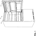
FIG. 1 is a front perspective view of an appliance of the present disclosure; -
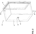
FIG. 2 is an expanded top perspective view of a vacuum insulated structure of the present disclosure; -
FIG. 3 is a top perspective view of a vacuum insulated structure of the present disclosure; -
FIG. 4 is a cross-sectional view of the vacuum insulated structure ofFIG. 2 taken along lines IV-IV; -
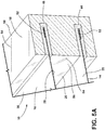
FIG. 5A is an enlarged cross-sectional view of a trim breaker of the vacuum insulated structure ofFIG. 4 taken at area VA; -
FIG. 5B is an enlarged cross-sectional view of a connector of the vacuum insulated structure ofFIG. 4 taken at area VB; -
FIG. 6 is a cross-sectional view of an evacuation chamber of the present disclosure that includes a vacuum insulated structure disposed between a support frame; and -
FIG. 7 is a flow diagram of a method for forming a vacuum insulated structure of the present disclosure. - The components in the figures are not necessarily to scale, emphasis instead being placed upon illustrating the principles described herein.
- The present illustrated embodiments reside primarily in combinations of method steps related to a method for manufacturing a vacuum insulated structure. Accordingly, the method steps have been represented, where appropriate, by conventional symbols in the drawings, showing only those specific details that are pertinent to understanding the embodiments of the present disclosure so as not to obscure the disclosure with details that will be readily apparent to those of ordinary skill in the art having the benefit of the description herein. Further, like numerals in the description and drawings represent like elements.
- For purposes of description herein, the terms "upper," "lower," "right," "left," "rear," "front," "vertical," "horizontal," and derivatives thereof shall relate to the disclosure as oriented in
FIG. 1 . Unless stated otherwise, the term "front" shall refer to the surface of the element closer to an intended viewer, and the term "rear" shall refer to the surface of the element further from the intended viewer. However, it is to be understood that the disclosure may assume various alternative orientations, except where expressly specified to the contrary. It is also to be understood that the specific devices and processes illustrated in the attached drawings, and described in the following specification are simply exemplary embodiments of the inventive concepts defined in the appended claims. Hence, specific dimensions and other physical characteristics relating to the embodiments disclosed herein are not to be considered as limiting, unless the claims expressly state otherwise. - The terms "including," "comprises," "comprising," or any other variation thereof, are intended to cover a non-exclusive inclusion, such that a process, method, article, or apparatus that comprises a list of elements does not include only those elements but may include other elements not expressly listed or inherent to such process, method, article, or apparatus. An element proceeded by "comprises a ... " does not, without more constraints, preclude the existence of additional identical elements in the process, method, article, or apparatus that comprises the element.
- Referring to
FIGS. 1-7 ,reference numeral 10 generally designates a vacuum insulated structure for anappliance 12 that includes afirst panel 14 coupled to asecond panel 16 via atrim breaker 18. Aninsulation cavity 20 is defined between thefirst panel 14 and thesecond panel 16, such thatinsulation materials 22 may be dispensed within theinsulation cavity 20. The vacuum insulatedstructure 10 is formed in anevacuation chamber 24 and is braced during evacuation of theevacuation chamber 24 by asupport frame 26, described in more detail below. - Referring to
FIGS. 1-4 , theappliance 12 is illustrated as a refrigerating appliance, but it is also contemplated that the vacuum insulatedstructure 10 described herein may be used with a variety of appliances or insulation purposes other than within an appliance. Moreover, the vacuum insulatedstructure 10 may be in the form of a vacuum insulated structural cabinet or a vacuum insulated panel that may be used as an insulation member for theappliance 12. According to various examples, the vacuum insulatedstructure 10 includes thefirst panel 14 and thesecond panel 16, mentioned above, which may form a liner and a wrapper, respectively. Thefirst panel 14 and thesecond panel 16 each have aninterior surface 28 and anexterior surface 30, such that theinterior surface 28 defines theinsulation cavity 20 in which theinsulation materials 22 are disposed. Thefirst panel 14 and thesecond panel 16 are typically formed from a metallic material, which minimizes potential exposure of theinsulation cavity 20 to air molecules. - It is generally contemplated that the
insulation materials 22 may be a glass-type material, a carbon-based powder, silicon oxide-based materials, insulating gasses, and other standard insulation materials known in the art. Theinsulation materials 22 are disposed via aport 32 to substantially fill theinsulation cavity 20 forming a substantially continuous layer between thefirst panel 14 and thesecond panel 16. Once theinsulation cavity 20 is substantially filled, theport 32 is sealed to close theinsulated structure 10 before evacuation, described in further detail below. - Referring to
FIGS. 2-5B , theinsulation cavity 20 is further defined by thetrim breaker 18, which couples thefirst panel 14 to thesecond panel 16, and aconnector 40, which is disposed around anaperture 42 defined by each of thefirst panel 14 and thesecond panel 16. Theconnector 40 provides a space through which wiring and other tubing for theappliance 12 may pass. As illustrated inFIG. 5A , thefirst panel 14 is disposed within afirst groove 44 of thetrim breaker 18, and thesecond panel 16 is disposed within asecond groove 46 of thetrim breaker 18. In addition, thefirst panel 14 is disposed within a firstcircumferential groove 48 of theconnector 40, and thesecond panel 16 is disposed within a secondcircumferential groove 50 of theconnector 40, as illustrated inFIG. 5B . Anadhesive 52 is disposed within each of thefirst groove 44, thesecond groove 46, the firstcircumferential groove 48, and the secondcircumferential groove 50 to securely couple thefirst panel 14 and thesecond panel 16, respectively, to thetrim breaker 18 and theconnector 40. - It is generally contemplated that the
trim breaker 18 and theconnector 40 are formed from a polymeric material, such as plastic. Conventional trim breakers and connectors are typically porous, such that, over time, air molecules can pass through conventional trim breakers and connectors into theinsulation cavity 20. Accordingly, thetrim breaker 18 and theconnector 40 of the present disclosure are evacuated, described in further detail below, to remove the air molecules present. Moreover, ametallic coating 54 is applied to the evacuatedtrim breaker 18 and the evacuatedconnector 40 to minimize future penetration of air molecules into theinsulation cavity 20. It is also contemplated that themetallic coating 54 may be applied regardless of whether thetrim breaker 18 and theconnector 40 are evacuated. Themetallic coating 54 can trap potential air molecules present in thetrim breaker 18 and theconnector 40, such that future air permeation is minimized by themetallic coating 54. - Referring to
FIGS. 3-5B , themetallic coating 54 seals thetrim breaker 18 and theconnector 40 from the pass-through of gasses into theinsulation cavity 20. Themetallic coating 54 can be formed from aluminum and can be applied to thetrim breaker 18 and theconnector 40 using physical vapor deposition. Themetallic coating 54 can be applied to thetrim breaker 18 and theconnector 40 in a vapor phase under physical vapor deposition, which then condenses to form the film on thetrim breaker 18 and theconnector 40. - While the
metallic coating 54 may be formed from an aluminum base, it is also contemplated that themetallic coating 54 can be chrome, titanium, or any other metal typically used in physical vapor deposition. Additionally or alternatively, themetallic coating 54 can be applied to thetrim breaker 18 using electroplating methods. Electroplating is a process in which thetrim breaker 18 and theconnector 40 are plated with themetallic coating 54, which typically results in a thicker coating as compared to using physical vapor deposition. The use of metals to form themetallic coating 54 forms a barrier, such that potential entry of gasses into theinsulated structure 10 is minimized. - With further reference to
FIGS. 3-5B , themetallic coating 54 is applied under a vacuum to secure themetallic coating 54 to thetrim breaker 18 and theconnector 40, described in further detail below. Themetallic coating 54 is applied to aninner channel 56 and anouter surface 58 of each of thetrim breaker 18 and theconnector 40. The application of themetallic coating 54 to both theinner channel 56 and theouter surface 58 further diminishes the rate of gas permeation into theinsulated structure 10. Thus, the integrity of theinsulated structure 10, whether the vacuum insulated structural cabinet or panel may be maintained, ultimately increases the useful life of theinsulated structure 10. Thus, coating thetrim breaker 18 and theconnector 40 generally minimizes outgassing into theinsulation cavity 20. - Referring now to
FIG. 6 , theinsulated structure 10, illustrated as an insulated panel, is disposed within theevacuation chamber 24 and is positioned between thesupport frame 26, described below. Alid 70 and abody 72 form theevacuation chamber 24 in which theinsulated structure 10 is disposed. Thelid 70 is sealed to thebody 72 using agasket 74 disposed along anupper portion 76 of thebody 72. Thelid 70 and thegasket 74 define a seal for theevacuation chamber 24, such that as a vacuum is drawn within theevacuation chamber 24, the vacuum defined within theevacuation chamber 24 is maintained. In order to draw the vacuum, it is generally contemplated that afirst vacuum pump 78 and asecond vacuum pump 80 are coupled to thebody 72 of theevacuation chamber 24. Thefirst vacuum pump 78 is configured to evacuate an interior cavity 82 of theevacuation chamber 24, such that theinsulated structure 10 positioned within theevacuation chamber 24 is also evacuated within the interior cavity 82 of theevacuation chamber 24. - The
second vacuum pump 80 extends through thebody 72 of theevacuation chamber 24 and is coupled to theinsulated structure 10 via avalve 84. Thevalve 84 is coupled to theport 32 of theinsulated structure 10, such that thesecond vacuum pump 80 draws a vacuum within theinsulation cavity 20 via thevalve 84. Air present within theinsulation cavity 20 is drawn out, or evacuated, as thesecond vacuum pump 80 draws the vacuum. It is generally contemplated that thefirst vacuum pump 78 and thesecond vacuum pump 80 can be activated simultaneously, such that the interior cavity 82 of theevacuation chamber 24 and theinsulation cavity 20 of theinsulated structure 10 are evacuated at approximately the same time. - Referring to
FIGS. 4-6 , first andsecond heaters bottom surface 94 of theevacuation chamber 24. Additionally or alternatively, the first and second first andsecond heaters evacuation chamber 24 proximate to theinsulated structure 10. It is also contemplated that asingle heater 90 may be used. The first andsecond heaters first panel 14 and thesecond panel 16 to thetrim breaker 18 and theconnector 40 to form theinsulated structure 10. The first andsecond heaters insulated structure 10 is evacuated and thetrim breaker 18 and theconnector 40 are outgassed. For example, as theinsulation materials 22 are heated by the first andsecond heaters insulation materials 22 are typically more energized and, as a result, the air molecules are easier to remove from theinsulation materials 22. Similarly, the air molecules present in the adhesive 52 are more rapidly removed as a result of the heat applied by the first andsecond heaters - Overall, the efficiency of the evacuation process is improved by keeping the
insulated structure 10 at a high temperature using the first andsecond heaters second heaters second heaters trim breaker 18 and theconnector 40. - While it is contemplated that the
trim breaker 18 and theconnector 40 can be outgassed under heated conditions prior to assembly of theinsulated structure 10, it is also contemplated that thetrim breaker 18 and theconnector 40 are heated and outgassed after being assembled with thefirst panel 14 and thesecond panel 16. For example, theinner channels 56 and theouter surfaces 58 of both thetrim breaker 18 and theconnector 40 are evacuated via both thefirst vacuum pump 78 and thesecond vacuum pump 80, which is further expedited via the first andsecond heaters - The
outer surfaces 58 of thetrim breaker 18 and theconnector 40 are typically evacuated more efficiently as a result of minimal resistance as compared to the potential interference withinsulation materials 22 and theinner channels 56 of thetrim breaker 18 and theconnector 40. Thus, the overall efficiency of the evacuation process can be increased by heating and simultaneously evacuating the interior cavity 82 of theevacuation chamber 24 and theinsulation cavity 20 of theinsulated structure 10. In addition, themetallic coating 54 can be applied under the vacuum to seal the evacuatedtrim breaker 18 andconnector 40. Themetallic coating 54 is typically cured during the curing of the adhesive 52 by way of the heat from the first andsecond heaters - Referring still to
FIGS. 4-6 , theinsulated structure 10 is braced by thesupport frame 26 as the interior cavity 82 of theevacuation chamber 24 is evacuated by thefirst vacuum pump 78. Thesupport frame 26 includes afirst frame portion 96 and asecond frame portion 98 that stabilizes theinsulated structure 10 as the interior cavity 82 is evacuated. The stabilization minimizes potential outward bowing of theinsulated structure 10 as a result of the vacuum pressure generated by thefirst vacuum pump 78. Thesupport frame 26 is configured to brace each side of theinsulated structure 10, such that thefirst panel 14 and thesecond panel 16 are braced on the exterior surfaces 30. For example, theinsulated structure 10 illustrated inFIG. 6 is an insulated panel braced between the first andsecond frame portions first frame portion 96 braces thefirst panel 14 and thesecond frame portion 98 braces thesecond panel 16. Thesupport frame 26 can also be configured to brace theinsulated structure 10 when it is formed from the liner and wrapper, such that thefirst frame portion 96 and thesecond frame portion 98 can be formed to similarly correspond to each of the liner and the wrapper, respectively. - Referring to
FIGS. 1-7 , themethod 200 for manufacturing the vacuum insulatedstructure 10 can begin with heating thetrim breaker 18 within the evacuation chamber 24 (step 202). It will be understood that the steps of the method may be performed in any order, simultaneously, and/or omitted without departing from the teachings provided herein. Prior to outgassing thetrim breaker 18, thefirst vacuum pump 78 is operably coupled to theevacuation chamber 24 to define thefirst vacuum pump 78 within the evacuation chamber 24 (step 204). Subsequently, theheated trim breaker 18 is outgassed using at least the first vacuum pump 78 (step 206). Themetallic coating 54 can then be applied to the trim breaker 18 (step 208). A similar process is used when heating, outgassing, and applying themetallic coating 54 to theconnector 40, which is generally described above (step 210). For example, themetallic coating 54 can be applied to thetrim breaker 18 and theconnector 40 using physical vapor deposition of aluminum (step 212). Additionally or alternatively, themetallic coating 54 can be applied by electroplating thetrim breaker 18 and the connector 40 (step 214). - The
first panel 14 and thesecond panel 16 are coupled to thetrim breaker 18 to form the insulated structure 10 (step 216). As mentioned above, thefirst panel 14 and thesecond panel 16 are adhered to thetrim breaker 18 using an adhesive 52 (step 218), which is cured by applying heat to the insulated structure 10 (step 220). Additionally or alternatively, the adhesive 52, thetrim breaker 18, and theconnector 40 may be evacuated while the adhesive 52 is being cured by the heat (step 221). Theinsulation cavity 20 is filled withinsulation materials 22, described above, via theport 32 disposed on thefirst panel 14 and/or the second panel 16 (step 222). Once theinsulation cavity 20 is filled, theport 32 is sealed (step 224). Theinsulated structure 10 is placed within the evacuation chamber 24 (step 226), which is operably coupled to thefirst vacuum pump 78. Theinsulated structure 10 is positioned within thesupport frame 26 between thefirst frame portion 96 and thesecond frame portion 98 within the evacuation chamber 24 (step 230). Thesecond vacuum pump 80 is operably coupled to the insulated structure 10 (step 232) once theinsulated structure 10 is positioned within thesupport frame 26. Thefirst vacuum pump 78 evacuates the interior cavity 82 of theevacuation chamber 24 and the exterior surfaces 30 of the insulated structure 10 (step 234), and thesecond vacuum pump 80 evacuates theinsulation cavity 20 of the insulated structure 10 (step 236). - During evacuation, the
insulated structure 10 braces against thesupport frame 26 while the interior cavity 82 of theevacuation chamber 24 is evacuated by the first vacuum pump 78 (step 238). The first andsecond heaters insulated structure 10 is heated by the first andsecond heaters - Referring still to
FIGS. 1-7 , theinsulation cavity 20 is defined by the metal of thefirst panel 14, thesecond panel 16, and themetallic coating 54. Accordingly, the metal of the first andsecond panels metallic coating 54 on thetrim breaker 18 form an envelope of materials that resist gas permeation. Further, the evacuation of theinsulated structure 10 under the heat generated by the first andsecond heaters metallic coating 54. Thus, the overall efficiency of forming theinsulated structure 10 is increased and improved. - According to the various examples, the
insulated structure 10 can be used in various appliances that can include, but are not limited to, refrigerators, freezers, coolers, ovens, dishwashers, laundry appliances, water heaters, and other similar appliances and fixtures within household and commercial settings. Additionally, theinsulation materials 22 can be a free-flowing material that can be poured, blown, compacted, or otherwise disposed within theinsulation cavity 20. This free-flowing material can be in the form of various silica-based materials, such as fumed silica, precipitated silica, nano-sized and/or micro-sided aerogel powder, rice husk ash powder, perlite, glass spheres, hollow glass spheres, cenospheres, diatomaceous earth, combinations thereof, and other similar insulating particulate material. - The invention disclosed herein is further summarized in the following paragraphs and is further characterized by combinations of any and all of the various aspects described therein.
- According to one aspect of the present disclosure, a method for manufacturing a vacuum insulated structure includes heating a trim breaker within an evacuation chamber. The method further includes outgassing the heated trim breaker via a first vacuum pump that is operably coupled to the evacuation chamber to define a vacuum within the evacuation chamber. The method further includes applying a metallic coating to the trim breaker, adhering the trim breaker to a first panel and a second panel via an adhesive to define an insulated structure, applying heat to the insulated structure to cure the adhesive, filling the insulated structure with insulation materials via ports, sealing the ports, positioning the heated insulated structure in the evacuation chamber, and evacuating the insulated structure via the first vacuum pump that is operably coupled to the evacuation chamber and a second vacuum pump that is operably coupled to the insulated structure.
- According to another aspect, evacuating a heated insulated structure includes evacuating an exterior surface of an insulated structure and an interior cavity of an evacuation chamber via a first vacuum pump.
- According to another aspect, the method includes evacuating an insulation cavity of an insulated structure via a second vacuum pump.
- According to another aspect, the method includes bracing an exterior surface of an insulated structure with a support frame.
- According to another aspect, applying a metallic coating includes using physical vapor deposition of aluminum on a trim breaker.
- According to another aspect, the method includes applying a metallic coating to a connector that is coupled to an aperture defined by each of a first panel and a second panel.
- According to another aspect, evacuating an insulated structure includes applying additional heat to an insulated structure within an evacuation chamber.
- According to another aspect of the present disclosure, a method for manufacturing a vacuum insulated structure includes applying a metallic coating to the trim breaker, adhering the trim breaker to a first panel and a second panel via an adhesive to define an insulated structure, curing the adhesive via heat, depositing insulation material within an insulation cavity defined between the first panel and the second panel, positioning the insulated structure in an evacuation chamber, evacuating the evacuation chamber via a first pump, and evacuating the insulated structure via a second pump.
- According to another aspect, the method includes applying a metallic coating to an inner channel and an external surface of a trim breaker.
- According to another aspect, the method includes evacuating a trim breaker via evacuation of an evacuation chamber via a first pump.
- According to another aspect, the method includes bracing an exterior surface of an insulated structure with a support frame.
- According to another aspect, the method includes outgassing a trim breaker via heat that is applied to an insulated structure.
- According to another aspect, the method includes coupling a connector to an aperture that is defined by a first panel and a second panel. The method further includes applying a metallic coating to the connector.
- According to yet another aspect of the present disclosure, a method for manufacturing a vacuum insulated structure includes adhering a trim breaker to a wrapper and a liner via an adhesive to define an insulated structure. The method further includes positioning the insulated structure within an evacuation chamber proximate to a first heater and a second heater. The method further includes heating the insulated structure and the evacuation chamber via the first heater and the second heater. The method further includes evacuating the evacuation chamber via a first vacuum pump, and evacuating the insulated structure via a second vacuum pump.
- According to another aspect, the method includes outgassing a trim breaker via a first heater and a second heater.
- According to another aspect, the method includes evacuating an external surface of a trim breaker via a first vacuum pump. The method further includes evacuating an inner channel of the trim breaker via a second vacuum pump.
- According to another aspect, the method includes applying a metallic coating to a trim breaker.
- According to another aspect, applying a metallic coating includes electroplating a trim breaker with the metallic coating.
- According to another aspect, the method includes positioning a first heater and a second heater proximate to a trim breaker. The method further includes applying heat to the trim breaker via the first heater and the second heater.
- According to another aspect, the method includes positioning an insulated structure within a support frame, and bracing the insulated structure via the support frame.
Claims (15)
- A method for manufacturing a vacuum insulated structure (10), comprising:adhering a trim breaker (18) to a wrapper and a liner via an adhesive (52) to define an insulated structure (10);positioning the insulated structure (10) within an evacuation chamber (24) proximate to a first heater and a second heater;heating the insulated structure (10) and the evacuation chamber (24) via the first heater and the second heater;evacuating the evacuation chamber (24) via a first vacuum pump (78); andevacuating the insulated structure (10) via a second vacuum pump (80).
- The method of claim 1, further comprising the step of:
applying a metallic coating (54) to the trim breaker (18). - The method of claim 2, wherein applying the metallic coating (54) further comprises the step of:
electroplating the trim breaker (18) with the metallic coating (54). - The method of either of claims 2 and 3, wherein applying the metallic coating (54) further comprises the step of:
using physical vapor deposition of aluminum on the trim breaker (18). - The method of any one of claims 2-4, further comprising the step of:
applying the metallic coating (54) to a connector (40) coupled to an aperture (42) defined by each of the wrapper and the liner. - The method of any one of claims 2-5, further comprising the steps of:coupling a connector (40) to an aperture (42) defined by the wrapper and the liner; andapplying the metallic coating (54) to the connector (40).
- The method of any one of claims 1-6, wherein evacuating the heated insulated structure (10) further comprises the step of:
evacuating an exterior surface (30) of the insulated structure (10) and an interior cavity (82) of the evacuation chamber (24) via the first vacuum pump (78). - The method of claim 7, further comprising the step of:
evacuating an insulation cavity (20) of the insulated structure (10) via the second vacuum pump (80). - The method of any one of claims 1-8, wherein further comprising the step of:
outgassing the trim breaker (18) via the first heater and the second heater. - The method of claim 9, wherein further comprising the steps of:evacuating an external surface (30) of the trim breaker (18) via the first vacuum pump (78); andevacuating an inner channel (56) of the trim breaker (18) via the second vacuum pump (80).
- The method of claim 10, further comprising the step of:
applying the metallic coating (54) to the inner channel (56) and the external surface (30) of the trim breaker (18). - The method of any one of claims 1-11, wherein further comprising the steps of:positioning the first heater and the second heater proximate to the trim breaker (18); andapplying heat to the trim breaker (18) via the first heater and the second heater.
- The method of any one of claims 1-12, wherein further comprising the steps of:positioning the insulated structure (10) within a support frame (26); andbracing the insulated structure (10) via the support frame (26).
- The method of any one of claims 1-13, further comprising the step of:
outgassing the trim breaker (18) via heat applied to the insulated structure (10). - The method of any one of claims 1-14, wherein evacuating the insulated structure (10) further comprises the step of:
applying additional heat to the insulated structure (10) within the evacuation chamber (24).
Applications Claiming Priority (1)
| Application Number | Priority Date | Filing Date | Title |
|---|---|---|---|
| US16/875,973 US11435132B2 (en) | 2020-05-15 | 2020-05-15 | Method for manufacturing a vacuum insulated structure |
Publications (2)
| Publication Number | Publication Date |
|---|---|
| EP3910270A1 true EP3910270A1 (en) | 2021-11-17 |
| EP3910270B1 EP3910270B1 (en) | 2022-12-07 |
Family
ID=75562548
Family Applications (1)
| Application Number | Title | Priority Date | Filing Date |
|---|---|---|---|
| EP21168729.8A Active EP3910270B1 (en) | 2020-05-15 | 2021-04-15 | Method for manufacturing a vacuum insulated structure |
Country Status (3)
| Country | Link |
|---|---|
| US (1) | US11435132B2 (en) |
| EP (1) | EP3910270B1 (en) |
| CN (1) | CN113674935A (en) |
Families Citing this family (2)
| Publication number | Priority date | Publication date | Assignee | Title |
|---|---|---|---|---|
| US11009284B2 (en) * | 2016-04-15 | 2021-05-18 | Whirlpool Corporation | Vacuum insulated refrigerator structure with three dimensional characteristics |
| GB2625541A (en) * | 2022-12-19 | 2024-06-26 | Oyster Thermal As | Thermoelectric vacuum-insulated container |
Citations (6)
| Publication number | Priority date | Publication date | Assignee | Title |
|---|---|---|---|---|
| GB726639A (en) * | 1952-09-27 | 1955-03-23 | Gen Electric | Improvements in and relating to insulating structures |
| JPH04337195A (en) * | 1991-05-14 | 1992-11-25 | Hitachi Ltd | vacuum insulation |
| EP0645576A1 (en) * | 1993-09-29 | 1995-03-29 | Aktiebolaget Electrolux | Method for filling and packing insulating powder in the walls of a cabinet body |
| CN102241101A (en) * | 2011-05-18 | 2011-11-16 | 合肥美的荣事达电冰箱有限公司 | Refrigerator negative-pressure foaming device and process |
| CN104260264A (en) * | 2011-01-05 | 2015-01-07 | 合肥美的电冰箱有限公司 | Foaming equipment, foaming technology and foaming technology of refrigeration plant |
| US20170190081A1 (en) * | 2015-12-30 | 2017-07-06 | Whirlpool Corporation | Method of fabricating 3d vacuum insulated refrigerator structure having core material |
Family Cites Families (13)
| Publication number | Priority date | Publication date | Assignee | Title |
|---|---|---|---|---|
| US2164143A (en) | 1934-11-10 | 1939-06-27 | Termisk Isolation Ab | Insulation |
| US2824364A (en) | 1952-10-23 | 1958-02-25 | Gen Electric | Method of assembling and evacuating an insulated vacuum panel |
| US3179549A (en) | 1964-06-10 | 1965-04-20 | Gen Electric | Thermal insulating panel and method of making the same |
| US4745015A (en) | 1981-09-30 | 1988-05-17 | The Dow Chemical Company | Thermal insulating panel |
| US5005557A (en) | 1985-11-29 | 1991-04-09 | Baechli Emil | Heat-insulating building and/or light element |
| US5094899A (en) | 1990-09-06 | 1992-03-10 | Owens-Corning Fiberglas Corporation | High r super insulation panel |
| US5609934A (en) | 1995-01-05 | 1997-03-11 | Schuller International, Inc. | Method of manufacturing heat bonded glass fiber insulation boards |
| ES2322128T3 (en) * | 2002-07-01 | 2009-06-17 | Whirlpool Corporation | A FIGURE CABINET ISOLATED TO VACUUM AND METHOD TO ASSESS THE THERMAL CONDUCTIVITY OF IT. |
| US6838146B2 (en) | 2002-09-09 | 2005-01-04 | Merrill Ezra L | Vacuum thermal insulation product and method for making same |
| WO2012012539A1 (en) * | 2010-07-20 | 2012-01-26 | Owens Corning Intellectual Capital, Llc | An apparatus and method for insulating an appliance |
| KR101417249B1 (en) * | 2011-02-21 | 2014-07-16 | (주)엘지하우시스 | Material for vacuum insulation pannel and method for fabricating the same |
| US20120285971A1 (en) | 2011-05-09 | 2012-11-15 | General Electric Company | Integrated vacuum insulation panel |
| WO2013123328A1 (en) | 2012-02-16 | 2013-08-22 | Alan Feinerman | Vacuum insulated panels of arbitrary size and the method for manufacturing the panels |
-
2020
- 2020-05-15 US US16/875,973 patent/US11435132B2/en active Active
-
2021
- 2021-04-15 EP EP21168729.8A patent/EP3910270B1/en active Active
- 2021-05-13 CN CN202110524423.3A patent/CN113674935A/en active Pending
Patent Citations (6)
| Publication number | Priority date | Publication date | Assignee | Title |
|---|---|---|---|---|
| GB726639A (en) * | 1952-09-27 | 1955-03-23 | Gen Electric | Improvements in and relating to insulating structures |
| JPH04337195A (en) * | 1991-05-14 | 1992-11-25 | Hitachi Ltd | vacuum insulation |
| EP0645576A1 (en) * | 1993-09-29 | 1995-03-29 | Aktiebolaget Electrolux | Method for filling and packing insulating powder in the walls of a cabinet body |
| CN104260264A (en) * | 2011-01-05 | 2015-01-07 | 合肥美的电冰箱有限公司 | Foaming equipment, foaming technology and foaming technology of refrigeration plant |
| CN102241101A (en) * | 2011-05-18 | 2011-11-16 | 合肥美的荣事达电冰箱有限公司 | Refrigerator negative-pressure foaming device and process |
| US20170190081A1 (en) * | 2015-12-30 | 2017-07-06 | Whirlpool Corporation | Method of fabricating 3d vacuum insulated refrigerator structure having core material |
Also Published As
| Publication number | Publication date |
|---|---|
| US20210356197A1 (en) | 2021-11-18 |
| CN113674935A (en) | 2021-11-19 |
| US11435132B2 (en) | 2022-09-06 |
| EP3910270B1 (en) | 2022-12-07 |
Similar Documents
| Publication | Publication Date | Title |
|---|---|---|
| CN107108102B (en) | vacuum container | |
| EP3910270B1 (en) | Method for manufacturing a vacuum insulated structure | |
| US11940205B2 (en) | Vacuum insulated structure | |
| CN1056123C (en) | Hot isolated container and production of same | |
| EP1216971A1 (en) | The method for manufacturing vacuum glazing and its application mechanical system | |
| EP3443283B1 (en) | Double cabinet vacuum insulated refrigerator with a structural foamed mullion | |
| EP3397909B1 (en) | Refrigerator cabinet and method of forming a vacuum insulated refrigerator cabinet structure | |
| US11692387B2 (en) | Insulated door assembly | |
| EP3696483B1 (en) | Trim breaker for a structural cabinet that incorporates a structural glass contact surface | |
| CN107257906A (en) | Vacuum heat insulator | |
| KR960700651A (en) | Insulated electric heating pot and its manufacturing method | |
| US20240344757A1 (en) | Insulation materials for a heat and sound insulated structure and methods of forming with a mold that is gas and liquid permeable | |
| WO2016157747A1 (en) | Vacuum insulation housing | |
| WO1999017154A1 (en) | Method of manufacturing a flat glass panel for a picture display device | |
| EP4455587A1 (en) | Feature for accelerating evacuation of a vacuum insulated structure | |
| US20230331625A1 (en) | Insulation materials for a vacuum insulated structure and methods of forming | |
| JP2659402B2 (en) | Manufacturing method of metal double-walled container | |
| US20260139888A1 (en) | Ice maker with sanitary evaporator | |
| US20160090976A1 (en) | Systems and methods for a dual purpose getter container | |
| CN113074495A (en) | Method for manufacturing vacuum heat insulator and refrigerator | |
| JPH05176846A (en) | Insulation container manufacturing method | |
| JPH07269778A (en) | Vacuum packed insulation | |
| JPH07149378A (en) | Thermal insulation container and manufacturing method thereof | |
| KR20090020343A (en) | Manufacturing Method of Plasma Display Panel Using Single Composite Process | |
| JPH05253082A (en) | Insulation container manufacturing method |
Legal Events
| Date | Code | Title | Description |
|---|---|---|---|
| PUAI | Public reference made under article 153(3) epc to a published international application that has entered the european phase |
Free format text: ORIGINAL CODE: 0009012 |
|
| STAA | Information on the status of an ep patent application or granted ep patent |
Free format text: STATUS: THE APPLICATION HAS BEEN PUBLISHED |
|
| AK | Designated contracting states |
Kind code of ref document: A1 Designated state(s): AL AT BE BG CH CY CZ DE DK EE ES FI FR GB GR HR HU IE IS IT LI LT LU LV MC MK MT NL NO PL PT RO RS SE SI SK SM TR |
|
| B565 | Issuance of search results under rule 164(2) epc |
Effective date: 20211012 |
|
| STAA | Information on the status of an ep patent application or granted ep patent |
Free format text: STATUS: REQUEST FOR EXAMINATION WAS MADE |
|
| 17P | Request for examination filed |
Effective date: 20220503 |
|
| RBV | Designated contracting states (corrected) |
Designated state(s): AL AT BE BG CH CY CZ DE DK EE ES FI FR GB GR HR HU IE IS IT LI LT LU LV MC MK MT NL NO PL PT RO RS SE SI SK SM TR |
|
| GRAP | Despatch of communication of intention to grant a patent |
Free format text: ORIGINAL CODE: EPIDOSNIGR1 |
|
| STAA | Information on the status of an ep patent application or granted ep patent |
Free format text: STATUS: GRANT OF PATENT IS INTENDED |
|
| GRAS | Grant fee paid |
Free format text: ORIGINAL CODE: EPIDOSNIGR3 |
|
| INTG | Intention to grant announced |
Effective date: 20221004 |
|
| GRAA | (expected) grant |
Free format text: ORIGINAL CODE: 0009210 |
|
| STAA | Information on the status of an ep patent application or granted ep patent |
Free format text: STATUS: THE PATENT HAS BEEN GRANTED |
|
| AK | Designated contracting states |
Kind code of ref document: B1 Designated state(s): AL AT BE BG CH CY CZ DE DK EE ES FI FR GB GR HR HU IE IS IT LI LT LU LV MC MK MT NL NO PL PT RO RS SE SI SK SM TR |
|
| REG | Reference to a national code |
Ref country code: GB Ref legal event code: FG4D |
|
| REG | Reference to a national code |
Ref country code: CH Ref legal event code: EP Ref country code: AT Ref legal event code: REF Ref document number: 1536539 Country of ref document: AT Kind code of ref document: T Effective date: 20221215 |
|
| REG | Reference to a national code |
Ref country code: DE Ref legal event code: R096 Ref document number: 602021000908 Country of ref document: DE |
|
| REG | Reference to a national code |
Ref country code: IE Ref legal event code: FG4D |
|
| REG | Reference to a national code |
Ref country code: LT Ref legal event code: MG9D |
|
| REG | Reference to a national code |
Ref country code: NL Ref legal event code: MP Effective date: 20221207 |
|
| PG25 | Lapsed in a contracting state [announced via postgrant information from national office to epo] |
Ref country code: SE Free format text: LAPSE BECAUSE OF FAILURE TO SUBMIT A TRANSLATION OF THE DESCRIPTION OR TO PAY THE FEE WITHIN THE PRESCRIBED TIME-LIMIT Effective date: 20221207 Ref country code: NO Free format text: LAPSE BECAUSE OF FAILURE TO SUBMIT A TRANSLATION OF THE DESCRIPTION OR TO PAY THE FEE WITHIN THE PRESCRIBED TIME-LIMIT Effective date: 20230307 Ref country code: LT Free format text: LAPSE BECAUSE OF FAILURE TO SUBMIT A TRANSLATION OF THE DESCRIPTION OR TO PAY THE FEE WITHIN THE PRESCRIBED TIME-LIMIT Effective date: 20221207 Ref country code: FI Free format text: LAPSE BECAUSE OF FAILURE TO SUBMIT A TRANSLATION OF THE DESCRIPTION OR TO PAY THE FEE WITHIN THE PRESCRIBED TIME-LIMIT Effective date: 20221207 Ref country code: ES Free format text: LAPSE BECAUSE OF FAILURE TO SUBMIT A TRANSLATION OF THE DESCRIPTION OR TO PAY THE FEE WITHIN THE PRESCRIBED TIME-LIMIT Effective date: 20221207 |
|
| REG | Reference to a national code |
Ref country code: AT Ref legal event code: MK05 Ref document number: 1536539 Country of ref document: AT Kind code of ref document: T Effective date: 20221207 |
|
| PG25 | Lapsed in a contracting state [announced via postgrant information from national office to epo] |
Ref country code: RS Free format text: LAPSE BECAUSE OF FAILURE TO SUBMIT A TRANSLATION OF THE DESCRIPTION OR TO PAY THE FEE WITHIN THE PRESCRIBED TIME-LIMIT Effective date: 20221207 Ref country code: PL Free format text: LAPSE BECAUSE OF FAILURE TO SUBMIT A TRANSLATION OF THE DESCRIPTION OR TO PAY THE FEE WITHIN THE PRESCRIBED TIME-LIMIT Effective date: 20221207 Ref country code: LV Free format text: LAPSE BECAUSE OF FAILURE TO SUBMIT A TRANSLATION OF THE DESCRIPTION OR TO PAY THE FEE WITHIN THE PRESCRIBED TIME-LIMIT Effective date: 20221207 Ref country code: HR Free format text: LAPSE BECAUSE OF FAILURE TO SUBMIT A TRANSLATION OF THE DESCRIPTION OR TO PAY THE FEE WITHIN THE PRESCRIBED TIME-LIMIT Effective date: 20221207 Ref country code: GR Free format text: LAPSE BECAUSE OF FAILURE TO SUBMIT A TRANSLATION OF THE DESCRIPTION OR TO PAY THE FEE WITHIN THE PRESCRIBED TIME-LIMIT Effective date: 20230308 |
|
| P01 | Opt-out of the competence of the unified patent court (upc) registered |
Effective date: 20230523 |
|
| PG25 | Lapsed in a contracting state [announced via postgrant information from national office to epo] |
Ref country code: NL Free format text: LAPSE BECAUSE OF FAILURE TO SUBMIT A TRANSLATION OF THE DESCRIPTION OR TO PAY THE FEE WITHIN THE PRESCRIBED TIME-LIMIT Effective date: 20221207 |
|
| PG25 | Lapsed in a contracting state [announced via postgrant information from national office to epo] |
Ref country code: SM Free format text: LAPSE BECAUSE OF FAILURE TO SUBMIT A TRANSLATION OF THE DESCRIPTION OR TO PAY THE FEE WITHIN THE PRESCRIBED TIME-LIMIT Effective date: 20221207 Ref country code: RO Free format text: LAPSE BECAUSE OF FAILURE TO SUBMIT A TRANSLATION OF THE DESCRIPTION OR TO PAY THE FEE WITHIN THE PRESCRIBED TIME-LIMIT Effective date: 20221207 Ref country code: PT Free format text: LAPSE BECAUSE OF FAILURE TO SUBMIT A TRANSLATION OF THE DESCRIPTION OR TO PAY THE FEE WITHIN THE PRESCRIBED TIME-LIMIT Effective date: 20230410 Ref country code: EE Free format text: LAPSE BECAUSE OF FAILURE TO SUBMIT A TRANSLATION OF THE DESCRIPTION OR TO PAY THE FEE WITHIN THE PRESCRIBED TIME-LIMIT Effective date: 20221207 Ref country code: CZ Free format text: LAPSE BECAUSE OF FAILURE TO SUBMIT A TRANSLATION OF THE DESCRIPTION OR TO PAY THE FEE WITHIN THE PRESCRIBED TIME-LIMIT Effective date: 20221207 Ref country code: AT Free format text: LAPSE BECAUSE OF FAILURE TO SUBMIT A TRANSLATION OF THE DESCRIPTION OR TO PAY THE FEE WITHIN THE PRESCRIBED TIME-LIMIT Effective date: 20221207 |
|
| PG25 | Lapsed in a contracting state [announced via postgrant information from national office to epo] |
Ref country code: SK Free format text: LAPSE BECAUSE OF FAILURE TO SUBMIT A TRANSLATION OF THE DESCRIPTION OR TO PAY THE FEE WITHIN THE PRESCRIBED TIME-LIMIT Effective date: 20221207 Ref country code: IS Free format text: LAPSE BECAUSE OF FAILURE TO SUBMIT A TRANSLATION OF THE DESCRIPTION OR TO PAY THE FEE WITHIN THE PRESCRIBED TIME-LIMIT Effective date: 20230407 Ref country code: AL Free format text: LAPSE BECAUSE OF FAILURE TO SUBMIT A TRANSLATION OF THE DESCRIPTION OR TO PAY THE FEE WITHIN THE PRESCRIBED TIME-LIMIT Effective date: 20221207 |
|
| REG | Reference to a national code |
Ref country code: DE Ref legal event code: R097 Ref document number: 602021000908 Country of ref document: DE |
|
| PLBE | No opposition filed within time limit |
Free format text: ORIGINAL CODE: 0009261 |
|
| STAA | Information on the status of an ep patent application or granted ep patent |
Free format text: STATUS: NO OPPOSITION FILED WITHIN TIME LIMIT |
|
| PG25 | Lapsed in a contracting state [announced via postgrant information from national office to epo] |
Ref country code: DK Free format text: LAPSE BECAUSE OF FAILURE TO SUBMIT A TRANSLATION OF THE DESCRIPTION OR TO PAY THE FEE WITHIN THE PRESCRIBED TIME-LIMIT Effective date: 20221207 |
|
| 26N | No opposition filed |
Effective date: 20230908 |
|
| PG25 | Lapsed in a contracting state [announced via postgrant information from national office to epo] |
Ref country code: SI Free format text: LAPSE BECAUSE OF FAILURE TO SUBMIT A TRANSLATION OF THE DESCRIPTION OR TO PAY THE FEE WITHIN THE PRESCRIBED TIME-LIMIT Effective date: 20221207 |
|
| PG25 | Lapsed in a contracting state [announced via postgrant information from national office to epo] |
Ref country code: LU Free format text: LAPSE BECAUSE OF NON-PAYMENT OF DUE FEES Effective date: 20230415 |
|
| REG | Reference to a national code |
Ref country code: BE Ref legal event code: MM Effective date: 20230430 |
|
| PG25 | Lapsed in a contracting state [announced via postgrant information from national office to epo] |
Ref country code: MC Free format text: LAPSE BECAUSE OF FAILURE TO SUBMIT A TRANSLATION OF THE DESCRIPTION OR TO PAY THE FEE WITHIN THE PRESCRIBED TIME-LIMIT Effective date: 20221207 |
|
| PG25 | Lapsed in a contracting state [announced via postgrant information from national office to epo] |
Ref country code: MC Free format text: LAPSE BECAUSE OF FAILURE TO SUBMIT A TRANSLATION OF THE DESCRIPTION OR TO PAY THE FEE WITHIN THE PRESCRIBED TIME-LIMIT Effective date: 20221207 |
|
| REG | Reference to a national code |
Ref country code: IE Ref legal event code: MM4A |
|
| PG25 | Lapsed in a contracting state [announced via postgrant information from national office to epo] |
Ref country code: BE Free format text: LAPSE BECAUSE OF NON-PAYMENT OF DUE FEES Effective date: 20230430 |
|
| PG25 | Lapsed in a contracting state [announced via postgrant information from national office to epo] |
Ref country code: IE Free format text: LAPSE BECAUSE OF NON-PAYMENT OF DUE FEES Effective date: 20230415 |
|
| PG25 | Lapsed in a contracting state [announced via postgrant information from national office to epo] |
Ref country code: IE Free format text: LAPSE BECAUSE OF NON-PAYMENT OF DUE FEES Effective date: 20230415 |
|
| PGFP | Annual fee paid to national office [announced via postgrant information from national office to epo] |
Ref country code: DE Payment date: 20240429 Year of fee payment: 4 |
|
| PGFP | Annual fee paid to national office [announced via postgrant information from national office to epo] |
Ref country code: IT Payment date: 20240430 Year of fee payment: 4 Ref country code: FR Payment date: 20240430 Year of fee payment: 4 |
|
| PG25 | Lapsed in a contracting state [announced via postgrant information from national office to epo] |
Ref country code: BG Free format text: LAPSE BECAUSE OF FAILURE TO SUBMIT A TRANSLATION OF THE DESCRIPTION OR TO PAY THE FEE WITHIN THE PRESCRIBED TIME-LIMIT Effective date: 20221207 |
|
| PG25 | Lapsed in a contracting state [announced via postgrant information from national office to epo] |
Ref country code: BG Free format text: LAPSE BECAUSE OF FAILURE TO SUBMIT A TRANSLATION OF THE DESCRIPTION OR TO PAY THE FEE WITHIN THE PRESCRIBED TIME-LIMIT Effective date: 20221207 |
|
| REG | Reference to a national code |
Ref country code: CH Ref legal event code: PL |
|
| PG25 | Lapsed in a contracting state [announced via postgrant information from national office to epo] |
Ref country code: CH Free format text: LAPSE BECAUSE OF NON-PAYMENT OF DUE FEES Effective date: 20240430 |
|
| PG25 | Lapsed in a contracting state [announced via postgrant information from national office to epo] |
Ref country code: CY Free format text: LAPSE BECAUSE OF FAILURE TO SUBMIT A TRANSLATION OF THE DESCRIPTION OR TO PAY THE FEE WITHIN THE PRESCRIBED TIME-LIMIT; INVALID AB INITIO Effective date: 20210415 |
|
| PG25 | Lapsed in a contracting state [announced via postgrant information from national office to epo] |
Ref country code: HU Free format text: LAPSE BECAUSE OF FAILURE TO SUBMIT A TRANSLATION OF THE DESCRIPTION OR TO PAY THE FEE WITHIN THE PRESCRIBED TIME-LIMIT; INVALID AB INITIO Effective date: 20210415 |
|
| REG | Reference to a national code |
Ref country code: DE Ref legal event code: R119 Ref document number: 602021000908 Country of ref document: DE |
|
| PG25 | Lapsed in a contracting state [announced via postgrant information from national office to epo] |
Ref country code: TR Free format text: LAPSE BECAUSE OF FAILURE TO SUBMIT A TRANSLATION OF THE DESCRIPTION OR TO PAY THE FEE WITHIN THE PRESCRIBED TIME-LIMIT Effective date: 20221207 |
|
| GBPC | Gb: european patent ceased through non-payment of renewal fee |
Effective date: 20250415 |
|
| PG25 | Lapsed in a contracting state [announced via postgrant information from national office to epo] |
Ref country code: DE Free format text: LAPSE BECAUSE OF NON-PAYMENT OF DUE FEES Effective date: 20251104 |
|
| PG25 | Lapsed in a contracting state [announced via postgrant information from national office to epo] |
Ref country code: GB Free format text: LAPSE BECAUSE OF NON-PAYMENT OF DUE FEES Effective date: 20250415 |
|
| PG25 | Lapsed in a contracting state [announced via postgrant information from national office to epo] |
Ref country code: FR Free format text: LAPSE BECAUSE OF NON-PAYMENT OF DUE FEES Effective date: 20250430 |
|
| PG25 | Lapsed in a contracting state [announced via postgrant information from national office to epo] |
Ref country code: IT Free format text: LAPSE BECAUSE OF NON-PAYMENT OF DUE FEES Effective date: 20250415 |