EP3910166A1 - Radial seal arrangement - Google Patents
Radial seal arrangement Download PDFInfo
- Publication number
- EP3910166A1 EP3910166A1 EP21172417.4A EP21172417A EP3910166A1 EP 3910166 A1 EP3910166 A1 EP 3910166A1 EP 21172417 A EP21172417 A EP 21172417A EP 3910166 A1 EP3910166 A1 EP 3910166A1
- Authority
- EP
- European Patent Office
- Prior art keywords
- seal
- radial surface
- inner radial
- seal ring
- shape
- Prior art date
- Legal status (The legal status is an assumption and is not a legal conclusion. Google has not performed a legal analysis and makes no representation as to the accuracy of the status listed.)
- Granted
Links
Images
Classifications
-
- F—MECHANICAL ENGINEERING; LIGHTING; HEATING; WEAPONS; BLASTING
- F01—MACHINES OR ENGINES IN GENERAL; ENGINE PLANTS IN GENERAL; STEAM ENGINES
- F01D—NON-POSITIVE DISPLACEMENT MACHINES OR ENGINES, e.g. STEAM TURBINES
- F01D11/00—Preventing or minimising internal leakage of working-fluid, e.g. between stages
- F01D11/003—Preventing or minimising internal leakage of working-fluid, e.g. between stages by packing rings; Mechanical seals
-
- F—MECHANICAL ENGINEERING; LIGHTING; HEATING; WEAPONS; BLASTING
- F01—MACHINES OR ENGINES IN GENERAL; ENGINE PLANTS IN GENERAL; STEAM ENGINES
- F01D—NON-POSITIVE DISPLACEMENT MACHINES OR ENGINES, e.g. STEAM TURBINES
- F01D25/00—Component parts, details, or accessories, not provided for in, or of interest apart from, other groups
- F01D25/16—Arrangement of bearings; Supporting or mounting bearings in casings
-
- F—MECHANICAL ENGINEERING; LIGHTING; HEATING; WEAPONS; BLASTING
- F01—MACHINES OR ENGINES IN GENERAL; ENGINE PLANTS IN GENERAL; STEAM ENGINES
- F01D—NON-POSITIVE DISPLACEMENT MACHINES OR ENGINES, e.g. STEAM TURBINES
- F01D25/00—Component parts, details, or accessories, not provided for in, or of interest apart from, other groups
- F01D25/18—Lubricating arrangements
- F01D25/183—Sealing means
-
- F—MECHANICAL ENGINEERING; LIGHTING; HEATING; WEAPONS; BLASTING
- F16—ENGINEERING ELEMENTS AND UNITS; GENERAL MEASURES FOR PRODUCING AND MAINTAINING EFFECTIVE FUNCTIONING OF MACHINES OR INSTALLATIONS; THERMAL INSULATION IN GENERAL
- F16J—PISTONS; CYLINDERS; SEALINGS
- F16J15/00—Sealings
- F16J15/16—Sealings between relatively-moving surfaces
- F16J15/164—Sealings between relatively-moving surfaces the sealing action depending on movements; pressure difference, temperature or presence of leaking fluid
-
- F—MECHANICAL ENGINEERING; LIGHTING; HEATING; WEAPONS; BLASTING
- F16—ENGINEERING ELEMENTS AND UNITS; GENERAL MEASURES FOR PRODUCING AND MAINTAINING EFFECTIVE FUNCTIONING OF MACHINES OR INSTALLATIONS; THERMAL INSULATION IN GENERAL
- F16J—PISTONS; CYLINDERS; SEALINGS
- F16J15/00—Sealings
- F16J15/16—Sealings between relatively-moving surfaces
- F16J15/26—Sealings between relatively-moving surfaces with stuffing-boxes for rigid sealing rings
-
- F—MECHANICAL ENGINEERING; LIGHTING; HEATING; WEAPONS; BLASTING
- F05—INDEXING SCHEMES RELATING TO ENGINES OR PUMPS IN VARIOUS SUBCLASSES OF CLASSES F01-F04
- F05D—INDEXING SCHEME FOR ASPECTS RELATING TO NON-POSITIVE-DISPLACEMENT MACHINES OR ENGINES, GAS-TURBINES OR JET-PROPULSION PLANTS
- F05D2230/00—Manufacture
- F05D2230/50—Building or constructing in particular ways
- F05D2230/51—Building or constructing in particular ways in a modular way, e.g. using several identical or complementary parts or features
-
- F—MECHANICAL ENGINEERING; LIGHTING; HEATING; WEAPONS; BLASTING
- F05—INDEXING SCHEMES RELATING TO ENGINES OR PUMPS IN VARIOUS SUBCLASSES OF CLASSES F01-F04
- F05D—INDEXING SCHEME FOR ASPECTS RELATING TO NON-POSITIVE-DISPLACEMENT MACHINES OR ENGINES, GAS-TURBINES OR JET-PROPULSION PLANTS
- F05D2230/00—Manufacture
- F05D2230/60—Assembly methods
-
- F—MECHANICAL ENGINEERING; LIGHTING; HEATING; WEAPONS; BLASTING
- F05—INDEXING SCHEMES RELATING TO ENGINES OR PUMPS IN VARIOUS SUBCLASSES OF CLASSES F01-F04
- F05D—INDEXING SCHEME FOR ASPECTS RELATING TO NON-POSITIVE-DISPLACEMENT MACHINES OR ENGINES, GAS-TURBINES OR JET-PROPULSION PLANTS
- F05D2240/00—Components
- F05D2240/55—Seals
-
- F—MECHANICAL ENGINEERING; LIGHTING; HEATING; WEAPONS; BLASTING
- F05—INDEXING SCHEMES RELATING TO ENGINES OR PUMPS IN VARIOUS SUBCLASSES OF CLASSES F01-F04
- F05D—INDEXING SCHEME FOR ASPECTS RELATING TO NON-POSITIVE-DISPLACEMENT MACHINES OR ENGINES, GAS-TURBINES OR JET-PROPULSION PLANTS
- F05D2250/00—Geometry
- F05D2250/20—Three-dimensional
- F05D2250/23—Three-dimensional prismatic
- F05D2250/231—Three-dimensional prismatic cylindrical
-
- F—MECHANICAL ENGINEERING; LIGHTING; HEATING; WEAPONS; BLASTING
- F05—INDEXING SCHEMES RELATING TO ENGINES OR PUMPS IN VARIOUS SUBCLASSES OF CLASSES F01-F04
- F05D—INDEXING SCHEME FOR ASPECTS RELATING TO NON-POSITIVE-DISPLACEMENT MACHINES OR ENGINES, GAS-TURBINES OR JET-PROPULSION PLANTS
- F05D2250/00—Geometry
- F05D2250/20—Three-dimensional
- F05D2250/23—Three-dimensional prismatic
- F05D2250/232—Three-dimensional prismatic conical
-
- F—MECHANICAL ENGINEERING; LIGHTING; HEATING; WEAPONS; BLASTING
- F05—INDEXING SCHEMES RELATING TO ENGINES OR PUMPS IN VARIOUS SUBCLASSES OF CLASSES F01-F04
- F05D—INDEXING SCHEME FOR ASPECTS RELATING TO NON-POSITIVE-DISPLACEMENT MACHINES OR ENGINES, GAS-TURBINES OR JET-PROPULSION PLANTS
- F05D2250/00—Geometry
- F05D2250/20—Three-dimensional
- F05D2250/24—Three-dimensional ellipsoidal
-
- F—MECHANICAL ENGINEERING; LIGHTING; HEATING; WEAPONS; BLASTING
- F05—INDEXING SCHEMES RELATING TO ENGINES OR PUMPS IN VARIOUS SUBCLASSES OF CLASSES F01-F04
- F05D—INDEXING SCHEME FOR ASPECTS RELATING TO NON-POSITIVE-DISPLACEMENT MACHINES OR ENGINES, GAS-TURBINES OR JET-PROPULSION PLANTS
- F05D2250/00—Geometry
- F05D2250/70—Shape
- F05D2250/71—Shape curved
- F05D2250/711—Shape curved convex
-
- F—MECHANICAL ENGINEERING; LIGHTING; HEATING; WEAPONS; BLASTING
- F05—INDEXING SCHEMES RELATING TO ENGINES OR PUMPS IN VARIOUS SUBCLASSES OF CLASSES F01-F04
- F05D—INDEXING SCHEME FOR ASPECTS RELATING TO NON-POSITIVE-DISPLACEMENT MACHINES OR ENGINES, GAS-TURBINES OR JET-PROPULSION PLANTS
- F05D2250/00—Geometry
- F05D2250/70—Shape
- F05D2250/71—Shape curved
- F05D2250/712—Shape curved concave
-
- F—MECHANICAL ENGINEERING; LIGHTING; HEATING; WEAPONS; BLASTING
- F05—INDEXING SCHEMES RELATING TO ENGINES OR PUMPS IN VARIOUS SUBCLASSES OF CLASSES F01-F04
- F05D—INDEXING SCHEME FOR ASPECTS RELATING TO NON-POSITIVE-DISPLACEMENT MACHINES OR ENGINES, GAS-TURBINES OR JET-PROPULSION PLANTS
- F05D2260/00—Function
- F05D2260/80—Diagnostics
-
- F—MECHANICAL ENGINEERING; LIGHTING; HEATING; WEAPONS; BLASTING
- F05—INDEXING SCHEMES RELATING TO ENGINES OR PUMPS IN VARIOUS SUBCLASSES OF CLASSES F01-F04
- F05D—INDEXING SCHEME FOR ASPECTS RELATING TO NON-POSITIVE-DISPLACEMENT MACHINES OR ENGINES, GAS-TURBINES OR JET-PROPULSION PLANTS
- F05D2260/00—Function
- F05D2260/81—Modelling or simulation
-
- F—MECHANICAL ENGINEERING; LIGHTING; HEATING; WEAPONS; BLASTING
- F05—INDEXING SCHEMES RELATING TO ENGINES OR PUMPS IN VARIOUS SUBCLASSES OF CLASSES F01-F04
- F05D—INDEXING SCHEME FOR ASPECTS RELATING TO NON-POSITIVE-DISPLACEMENT MACHINES OR ENGINES, GAS-TURBINES OR JET-PROPULSION PLANTS
- F05D2260/00—Function
- F05D2260/82—Forecasts
Definitions
- Exemplary embodiments of the present invention pertain to the art of gas turbine engines, and in particular to radial seal arrangements of gas turbine engines.
- Advanced, high-performance gas turbine engines will require improved performance main shaft bearing compartment seals while also being required to meet more aggressive cost, weight, size, environmental and reliability metrics.
- Carbon seals enable the engine and bearing compartment to function with minimal impact on Thrust Specific Fuel Consumption (TSFC), the Thermal Management System (TMS) and the Lubrication System.
- TSFC Thrust Specific Fuel Consumption
- TMS Thermal Management System
- Lubrication System Such gas turbine engines require seals with improved wear resistance, improved performance, and improved reliability in order to meet customer/program metrics.
- Typical radial seals often experience elevated segmented carbon element radial wear and seal runner distress and/or deterioration, which results in increased air leakage characteristics and compromises bearing compartment oil containment.
- Advanced gas turbine engine contain main shaft seals which are higher in rubbing velocity than our prior engine experience, which demand alternate solutions.
- the nature of the problem is that traditional methods for setting the pre-profile or pre-taper on the radial inner diameter sealing surface of the sealing rings causes the operational contact pressure to be elevated due to incorrect assumptions and non-optimized profile shape. This prior art method thus results in reduced contact area during operational thermal-structural deflections of the seal runner when the sealing rings are in contact. This increased contact pressure results in increased seal ring wear and engine/system impacts which could impact customer satisfaction and metrics (e.g. reduced service life, premature maintenance).
- a seal assembly includes a rotating seal runner having an outer radial surface, and one or more rotationally stationary seal rings located radially outboard of the seal runner.
- Each seal ring has an inner radial surface, with the inner radial surface and the outer radial surface defining a sealing interface therebetween.
- An axially extending shape of the inner radial surface is selected utilizing a predicted shape of the outer radial surface at a selected operating condition of the seal assembly.
- the one or more seal rings includes a first seal ring, and a second seal axially aftward of the first seal ring.
- the first seal ring has a first inner radial surface shape and the second seal ring has a second inner radial surface shape different from the first inner radial surface shape.
- the selected operating condition is at an elevated operating temperature relative to ambient conditions.
- a shape of the outer radial surface at ambient conditions differs from the predicted shape of the outer radial surface at the selected operating condition.
- the axially extending shape of the inner radial surface is one or more of convex, concave or linear.
- the one or more seal rings are retained in a seal housing.
- a gas turbine engine includes a combustor, a turbine driven by products of the combustor, a compressor operably connected to the turbine and driven by rotation of the turbine, and a seal assembly to seal between a rotating component and a rotationally stationary component of the gas turbine engine.
- the seal assembly includes a rotating seal runner located at the rotating component having an outer radial surface, and one or more rotationally stationary seal rings located radially outboard of the seal runner at the rotationally stationary component.
- Each seal ring has an inner radial surface.
- the inner radial surface and the outer radial surface define a sealing interface therebetween.
- An axially extending shape of the inner radial surface is selected utilizing a predicted shape of the outer radial surface at a selected operating condition of the seal assembly.
- the one or more seal rings includes a first seal ring, and a second seal axially aftward of the first seal ring.
- the first seal ring has a first inner radial surface shape and the second seal ring has a second inner radial surface shape different from the first inner radial surface shape.
- the selected operating condition is at an elevated operating temperature relative to ambient conditions.
- a shape of the outer radial surface at ambient conditions differs from the predicted shape of the outer radial surface at the selected operating condition.
- the axially extending shape of the inner radial surface is one or more of convex, concave or linear.
- the one or more seal rings are retained in a seal housing.
- the rotating component is a shaft of the gas turbine engine.
- a bearing system is supportive of the shaft, and the seal assembly is configured to seal the bearing system.
- a method of assembling a seal assembly includes predicting an outer radial surface shape of a seal runner at one or more operating conditions of the seal assembly, selecting complimentary seal ring inner radial surface shapes of one or more seal rings based on the predicted outer radial surface shape, manufacturing the one or more seal rings to provide the selected seal ring inner radial surface shapes, and installing the one or more seal rings radially outboard of the seal runner such that a seal interface is defined between the outer radial surface and the inner radial surface.
- the outer radial surface shape is predicted via thermo-structural analysis.
- the one or more seal rings includes a first seal ring, and a second seal axially aftward of the first seal ring.
- the first seal ring has a first inner radial surface shape and the second seal ring has a second inner radial surface shape different from the first inner radial surface shape.
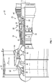
- FIG. 1 schematically illustrates a gas turbine engine 20.
- the gas turbine engine 20 is disclosed herein as a two-spool turbofan that generally incorporates a fan section 22, a compressor section 24, a combustor section 26 and a turbine section 28.
- Alternative engines might include other systems or features.
- the fan section 22 drives air along a bypass flow path B in a bypass duct, while the compressor section 24 drives air along a core flow path C for compression and communication into the combustor section 26 then expansion through the turbine section 28.
- FIG. 1 schematically illustrates a gas turbine engine 20.
- the gas turbine engine 20 is disclosed herein as a two-spool turbofan that generally incorporates a fan section 22, a compressor section 24, a combustor section 26 and a turbine section 28.
- Alternative engines might include other systems or features.
- the fan section 22 drives air along a bypass flow path B in a bypass duct
- the compressor section 24 drives air along a core flow path C for compression and communication into the combustor section 26
- the exemplary engine 20 generally includes a low speed spool 30 and a high speed spool 32 mounted for rotation about an engine central longitudinal axis A relative to an engine static structure 36 via several bearing systems 38. It should be understood that various bearing systems 38 at various locations may alternatively or additionally be provided, and the location of bearing systems 38 may be varied as appropriate to the application.
- the low speed spool 30 generally includes an inner shaft 40 that interconnects a fan 42, a low pressure compressor 44 and a low pressure turbine 46.
- the inner shaft 40 is connected to the fan 42 through a speed change mechanism, which in exemplary gas turbine engine 20 is illustrated as a geared architecture 48 to drive the fan 42 at a lower speed than the low speed spool 30.
- the high speed spool 32 includes an outer shaft 50 that interconnects a high pressure compressor 52 and high pressure turbine 54.
- a combustor 56 is arranged in exemplary gas turbine 20 between the high pressure compressor 52 and the high pressure turbine 54.
- An engine static structure 36 is arranged generally between the high pressure turbine 54 and the low pressure turbine 46.
- the engine static structure 36 further supports bearing systems 38 in the turbine section 28.
- the inner shaft 40 and the outer shaft 50 are concentric and rotate via bearing systems 38 about the engine central longitudinal axis A which is collinear with their longitudinal axes.
- each of the positions of the fan section 22, compressor section 24, combustor section 26, turbine section 28, and fan drive gear system 48 may be varied.
- gear system 48 may be located aft of combustor section 26 or even aft of turbine section 28, and fan section 22 may be positioned forward or aft of the location of gear system 48.
- the engine 20 in one example is a high-bypass geared aircraft engine.
- the engine 20 bypass ratio is greater than about six (6), with an example embodiment being greater than about ten (10)
- the geared architecture 48 is an epicyclic gear train, such as a planetary gear system or other gear system, with a gear reduction ratio of greater than about 2.3
- the low pressure turbine 46 has a pressure ratio that is greater than about five.
- the engine 20 bypass ratio is greater than about ten (10:1)
- the fan diameter is significantly larger than that of the low pressure compressor 44
- the low pressure turbine 46 has a pressure ratio that is greater than about five 5:1.
- Low pressure turbine 46 pressure ratio is pressure measured prior to inlet of low pressure turbine 46 as related to the pressure at the outlet of the low pressure turbine 46 prior to an exhaust nozzle.
- the geared architecture 48 may be an epicycle gear train, such as a planetary gear system or other gear system, with a gear reduction ratio of greater than about 2.3:1. It should be understood, however, that the above parameters are only exemplary of one embodiment of a geared architecture engine and that the present disclosure is applicable to other gas turbine engines including direct drive turbofans.
- the fan section 22 of the engine 20 is designed for a particular flight condition--typically cruise at about 0.8Mach and about 35,000 feet (10,688 meters).
- 'TSFC' Thrust Specific Fuel Consumption
- Low fan pressure ratio is the pressure ratio across the fan blade alone, without a Fan Exit Guide Vane (“FEGV”) system.
- the low fan pressure ratio as disclosed herein according to one non-limiting embodiment is less than about 1.45.
- Low corrected fan tip speed is the actual fan tip speed in ft/sec divided by an industry standard temperature correction of [(Tram °R)/(518.7 °R)] 0.5 .
- the "Low corrected fan tip speed” as disclosed herein according to one non-limiting embodiment is less than about 1150 ft/second (350.5 m/sec).
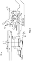
- the bearing system 38 supports a rotating shaft 60, which may be inner shaft 40 or outer shaft 50. While bearing system 38 as shown and described herein as supportive of shaft 60, one skilled in the art will readily appreciate that the bearing system 38 may be supportive of other rotating components of the gas turbine engine 20.
- the bearing system 38 includes a bearing inner race 62 located at the shaft 60 and rotatable with the shaft 60.
- a stationary bearing outer race 64 is located at and secured to a fixed structure 66 of the gas turbine engine 20.
- a bearing element 68 is located radially between the bearing inner race 62 and the bearing outer race 64.
- the bearing system 38 also includes one or more seal assemblies 70 to define a bearing compartment 72, providing for sealing and lubrication of the bearing system 38.
- the seal assembly 70 includes a seal runner 74 secured to and rotating with the shaft 60, and one or more seal rings 76 located radially outboard of the seal runner 74. In some embodiments, two seal rings 76, first seal ring 76a and second seal ring 76b are utilized. First seal ring 76a may be located axially forward of second seal ring 76b.
- the seal rings 76 are located in and retained in a seal housing 78 located radially outboard of the seal rings 76, and secured to the fixed structure 66. While the seal runner 74 rotates with the shaft 60, the seal rings 76 are rotationally stationary.
- the seal runner 74 includes a seal runner outer radial surface 80 and each seal ring 76a, 76b similarly includes a seal ring inner radial surface 82a, 82b.
- the seal runner outer radial surface 80 and the seal ring inner radial surface 82a, 82b are in radial contact and define a seal interface 84 therebetween. It desired to have uniform contact between the seal runner outer radial surface 80 and the seal ring inner radial surface 82a, 82b to reduce seal wear and contact pressure, and thereby maintaining performance of the seal assembly 70.
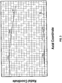
- thermo-structural analysis is performed at a selected operational condition of the gas turbine engine 20 to determine a predicted high power operational seal runner outer radial surface shape 90, which differs from a colder, lower power seal runner contact surface shape 92.
- the seal rings 76a, 76b are configured at the initial manufacturing, cold condition have respective cold seal ring inner radial surface shapes 94a, 94b in the axial and radial coordinate direction.
- the cold seal ring inner radial surface shapes 94a, 94b substantially match the high power operational seal runner outer radial surface shape 90, such that the cold seal ring inner radial surface shapes 94a, 94b substantially match high power operational seal ring inner radial surface shapes 96a, 96b, respectively. In other embodiments, the cold seal ring inner radial surface shapes 94a, 94b do not substantially match the high power operational seal ring inner radial surface shapes 96a, 96b.
- one operational condition may be utilized, while in other embodiments a multiple number of operational conditions, or a combination of operational conditions may be utilized to configure the seal ring inner radial surface shapes 96a, 96b.
- the high power operational seal runner outer radial surface shape 90 may differ from a low power seal runner outer radial surface shape 92.
- seal ring inner radial surface shape 94a may differ from the seal ring inner radial surface shape 94b.
- the high power operating condition is at a higher temperature than typical ambient temperature.
- the initial manufacturing, or cold operating condition is in a temperature range of -65 degrees Fahrenheit (-54 °C) to 200 degrees Fahrenheit (90 °C), while the high power operating condition is in a temperature range of 200 degrees Fahrenheit (90 °C) and above, in some embodiments up to 1000 degrees Fahrenheit (540 °C).
- Substantially conforming the high power operational seal ring inner radial surface shapes 94a, 94b to the high power operational seal runner outer radial surface shape 90 increases contact area of the seal ring 76 to the seal runner 74 during operation of the gas turbine engine 20 reduces operational contact pressure at the seal interface 84 thereby reducing seal wear.
- the seal ring inner radial surface shapes 94a, 94b may be manufactured as a concave shape, convex shape, linear shape, or other shape depending on the thermo-structural predictions.
- thermo-structural analysis determines the high power operational seal runner outer radial surface shape 90 at one or more high power operating conditions of the gas turbine engine 20.
- the seal ring inner radial surface shapes 96a, 96b are then selected based on the thermo-structural analysis results of runner outer radial surface shape 90 to increase contact area and reduce contact pressure during operation of the gas turbine engine 20.
- the seal rings 76a, 76b are manufactured to provide the selected seal ring inner radial surface shapes 96a, 96b.
- the seal rings 76a, 76b are installed over the seal runner 74.
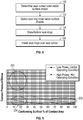
- a first portion 200 of the graph illustrates a contact pressure of a typical prior art seal assembly.
- a second portion 202 illustrates a contact pressure of the seal assembly 70 at the high power operating condition, having a greater percent contact area than the prior art seal assembly.
- a third portion 204 illustrates a contact pressure of the seal assembly 70 at the cold operating condition, illustrating that while the percent contact area is reduced at the cold operating condition, the contact pressure does not greatly increase, thus the effect on seal assembly 70 wear is small.
- seal assemblies 70 Utilizing the seal assemblies 70 disclosed herein enables improvements in seal assembly reliability, improved customer satisfaction, and reduced aircraft/engine overhaul cycle requirements.
- the present seal assemblies 70 differs from prior technology by incorporating actual thermal-structural predictions into the manufactured pre-profile of the seal ring 76. This key difference enables improved system solutions/metrics and extended seal wear life.
Landscapes
- Engineering & Computer Science (AREA)
- General Engineering & Computer Science (AREA)
- Mechanical Engineering (AREA)
- Turbine Rotor Nozzle Sealing (AREA)
Abstract
Description
- Exemplary embodiments of the present invention pertain to the art of gas turbine engines, and in particular to radial seal arrangements of gas turbine engines.
- Advanced, high-performance gas turbine engines will require improved performance main shaft bearing compartment seals while also being required to meet more aggressive cost, weight, size, environmental and reliability metrics. Carbon seals enable the engine and bearing compartment to function with minimal impact on Thrust Specific Fuel Consumption (TSFC), the Thermal Management System (TMS) and the Lubrication System. Such gas turbine engines require seals with improved wear resistance, improved performance, and improved reliability in order to meet customer/program metrics.
- Typical radial seals often experience elevated segmented carbon element radial wear and seal runner distress and/or deterioration, which results in increased air leakage characteristics and compromises bearing compartment oil containment. Advanced gas turbine engine contain main shaft seals which are higher in rubbing velocity than our prior engine experience, which demand alternate solutions. The nature of the problem is that traditional methods for setting the pre-profile or pre-taper on the radial inner diameter sealing surface of the sealing rings causes the operational contact pressure to be elevated due to incorrect assumptions and non-optimized profile shape. This prior art method thus results in reduced contact area during operational thermal-structural deflections of the seal runner when the sealing rings are in contact. This increased contact pressure results in increased seal ring wear and engine/system impacts which could impact customer satisfaction and metrics (e.g. reduced service life, premature maintenance).
- According to a first aspect, a seal assembly includes a rotating seal runner having an outer radial surface, and one or more rotationally stationary seal rings located radially outboard of the seal runner. Each seal ring has an inner radial surface, with the inner radial surface and the outer radial surface defining a sealing interface therebetween. An axially extending shape of the inner radial surface is selected utilizing a predicted shape of the outer radial surface at a selected operating condition of the seal assembly.
- Optionally, the one or more seal rings includes a first seal ring, and a second seal axially aftward of the first seal ring.
- Optionally, the first seal ring has a first inner radial surface shape and the second seal ring has a second inner radial surface shape different from the first inner radial surface shape.
- Optionally, the selected operating condition is at an elevated operating temperature relative to ambient conditions.
- Optionally, a shape of the outer radial surface at ambient conditions differs from the predicted shape of the outer radial surface at the selected operating condition.
- Optionally, the axially extending shape of the inner radial surface is one or more of convex, concave or linear.
- Optionally, the one or more seal rings are retained in a seal housing.
- According to another aspect, a gas turbine engine includes a combustor, a turbine driven by products of the combustor, a compressor operably connected to the turbine and driven by rotation of the turbine, and a seal assembly to seal between a rotating component and a rotationally stationary component of the gas turbine engine. The seal assembly includes a rotating seal runner located at the rotating component having an outer radial surface, and one or more rotationally stationary seal rings located radially outboard of the seal runner at the rotationally stationary component. Each seal ring has an inner radial surface. The inner radial surface and the outer radial surface define a sealing interface therebetween. An axially extending shape of the inner radial surface is selected utilizing a predicted shape of the outer radial surface at a selected operating condition of the seal assembly.
- Optionally, the one or more seal rings includes a first seal ring, and a second seal axially aftward of the first seal ring.
- Optionally, the first seal ring has a first inner radial surface shape and the second seal ring has a second inner radial surface shape different from the first inner radial surface shape.
- Optionally, the selected operating condition is at an elevated operating temperature relative to ambient conditions.
- Optionally, a shape of the outer radial surface at ambient conditions differs from the predicted shape of the outer radial surface at the selected operating condition.
- Optionally, the axially extending shape of the inner radial surface is one or more of convex, concave or linear.
- Optionally, the one or more seal rings are retained in a seal housing.
- Optionally, the rotating component is a shaft of the gas turbine engine.
- Optionally, a bearing system is supportive of the shaft, and the seal assembly is configured to seal the bearing system.
- According to yet another aspect, a method of assembling a seal assembly includes predicting an outer radial surface shape of a seal runner at one or more operating conditions of the seal assembly, selecting complimentary seal ring inner radial surface shapes of one or more seal rings based on the predicted outer radial surface shape, manufacturing the one or more seal rings to provide the selected seal ring inner radial surface shapes, and installing the one or more seal rings radially outboard of the seal runner such that a seal interface is defined between the outer radial surface and the inner radial surface.
- Optionally, the outer radial surface shape is predicted via thermo-structural analysis.
- Optionally, the one or more seal rings includes a first seal ring, and a second seal axially aftward of the first seal ring.
- Optionally, the first seal ring has a first inner radial surface shape and the second seal ring has a second inner radial surface shape different from the first inner radial surface shape.
- The following descriptions of exemplary embodiments are by way of example only and should not be considered limiting in any way. With reference to the accompanying drawings, like elements are numbered alike:
-
FIG. 1 is a partial cross-sectional view of a gas turbine engine; -
FIG. 2 is a partial cross-sectional view of a bearing system; -
FIG. 3 is an illustration of seal ring profile shape versus seal runner profile shape; -
FIG. 4 is a schematic illustration of a method of assembling a seal assembly; and -
FIG. 5 illustrates a contact pressure versus percent contact area for a seal assembly. - A detailed description of one or more embodiments of the disclosed apparatus and method are presented herein by way of exemplification and not limitation with reference to the Figures.
-
FIG. 1 schematically illustrates agas turbine engine 20. Thegas turbine engine 20 is disclosed herein as a two-spool turbofan that generally incorporates afan section 22, acompressor section 24, acombustor section 26 and aturbine section 28. Alternative engines might include other systems or features. Thefan section 22 drives air along a bypass flow path B in a bypass duct, while thecompressor section 24 drives air along a core flow path C for compression and communication into thecombustor section 26 then expansion through theturbine section 28. Although depicted as a two-spool turbofan gas turbine engine in the disclosed non-limiting embodiment, it should be understood that the concepts described herein are not limited to use with two-spool turbofans as the teachings may be applied to other types of turbine engines including three-spool architectures. - The
exemplary engine 20 generally includes alow speed spool 30 and ahigh speed spool 32 mounted for rotation about an engine central longitudinal axis A relative to an enginestatic structure 36 viaseveral bearing systems 38. It should be understood thatvarious bearing systems 38 at various locations may alternatively or additionally be provided, and the location ofbearing systems 38 may be varied as appropriate to the application. - The
low speed spool 30 generally includes aninner shaft 40 that interconnects afan 42, alow pressure compressor 44 and alow pressure turbine 46. Theinner shaft 40 is connected to thefan 42 through a speed change mechanism, which in exemplarygas turbine engine 20 is illustrated as a gearedarchitecture 48 to drive thefan 42 at a lower speed than thelow speed spool 30. Thehigh speed spool 32 includes anouter shaft 50 that interconnects ahigh pressure compressor 52 andhigh pressure turbine 54. Acombustor 56 is arranged inexemplary gas turbine 20 between thehigh pressure compressor 52 and thehigh pressure turbine 54. An enginestatic structure 36 is arranged generally between thehigh pressure turbine 54 and thelow pressure turbine 46. The enginestatic structure 36 further supports bearingsystems 38 in theturbine section 28. Theinner shaft 40 and theouter shaft 50 are concentric and rotate viabearing systems 38 about the engine central longitudinal axis A which is collinear with their longitudinal axes. - The core airflow is compressed by the
low pressure compressor 44 then thehigh pressure compressor 52, mixed and burned with fuel in thecombustor 56, then expanded over thehigh pressure turbine 54 andlow pressure turbine 46. Theturbines low speed spool 30 andhigh speed spool 32 in response to the expansion. It will be appreciated that each of the positions of thefan section 22,compressor section 24,combustor section 26,turbine section 28, and fandrive gear system 48 may be varied. For example,gear system 48 may be located aft ofcombustor section 26 or even aft ofturbine section 28, andfan section 22 may be positioned forward or aft of the location ofgear system 48. - The
engine 20 in one example is a high-bypass geared aircraft engine. In a further example, theengine 20 bypass ratio is greater than about six (6), with an example embodiment being greater than about ten (10), the gearedarchitecture 48 is an epicyclic gear train, such as a planetary gear system or other gear system, with a gear reduction ratio of greater than about 2.3 and thelow pressure turbine 46 has a pressure ratio that is greater than about five. In one disclosed embodiment, theengine 20 bypass ratio is greater than about ten (10:1), the fan diameter is significantly larger than that of thelow pressure compressor 44, and thelow pressure turbine 46 has a pressure ratio that is greater than about five 5:1.Low pressure turbine 46 pressure ratio is pressure measured prior to inlet oflow pressure turbine 46 as related to the pressure at the outlet of thelow pressure turbine 46 prior to an exhaust nozzle. The gearedarchitecture 48 may be an epicycle gear train, such as a planetary gear system or other gear system, with a gear reduction ratio of greater than about 2.3:1. It should be understood, however, that the above parameters are only exemplary of one embodiment of a geared architecture engine and that the present disclosure is applicable to other gas turbine engines including direct drive turbofans. - A significant amount of thrust is provided by the bypass flow B due to the high bypass ratio. The
fan section 22 of theengine 20 is designed for a particular flight condition--typically cruise at about 0.8Mach and about 35,000 feet (10,688 meters). The flight condition of 0.8 Mach and 35,000 ft (10,688 meters), with the engine at its best fuel consumption--also known as "bucket cruise Thrust Specific Fuel Consumption ('TSFC')"--is the industry standard parameter of lbm of fuel being burned divided by lbf of thrust the engine produces at that minimum point. "Low fan pressure ratio" is the pressure ratio across the fan blade alone, without a Fan Exit Guide Vane ("FEGV") system. The low fan pressure ratio as disclosed herein according to one non-limiting embodiment is less than about 1.45. "Low corrected fan tip speed" is the actual fan tip speed in ft/sec divided by an industry standard temperature correction of [(Tram °R)/(518.7 °R)]0.5. The "Low corrected fan tip speed" as disclosed herein according to one non-limiting embodiment is less than about 1150 ft/second (350.5 m/sec). - Referring to
FIG. 2 , illustrated is an embodiment of abearing system 38. The bearingsystem 38 supports arotating shaft 60, which may beinner shaft 40 orouter shaft 50. While bearingsystem 38 as shown and described herein as supportive ofshaft 60, one skilled in the art will readily appreciate that the bearingsystem 38 may be supportive of other rotating components of thegas turbine engine 20. The bearingsystem 38 includes a bearinginner race 62 located at theshaft 60 and rotatable with theshaft 60. A stationary bearingouter race 64 is located at and secured to a fixedstructure 66 of thegas turbine engine 20. A bearingelement 68 is located radially between the bearinginner race 62 and the bearingouter race 64. - The bearing
system 38 also includes one ormore seal assemblies 70 to define abearing compartment 72, providing for sealing and lubrication of the bearingsystem 38. Theseal assembly 70 includes aseal runner 74 secured to and rotating with theshaft 60, and one or more seal rings 76 located radially outboard of theseal runner 74. In some embodiments, two seal rings 76,first seal ring 76a andsecond seal ring 76b are utilized.First seal ring 76a may be located axially forward ofsecond seal ring 76b. The seal rings 76 are located in and retained in aseal housing 78 located radially outboard of the seal rings 76, and secured to the fixedstructure 66. While theseal runner 74 rotates with theshaft 60, the seal rings 76 are rotationally stationary. - The
seal runner 74 includes a seal runner outerradial surface 80 and eachseal ring radial surface radial surface 80 and the seal ring innerradial surface seal interface 84 therebetween. It desired to have uniform contact between the seal runner outerradial surface 80 and the seal ring innerradial surface seal assembly 70. Due to differences in thermo-structural properties and performance between theseal runner 74 and the seal rings 76, fit of the seal rings 76 to theseal runner 74 at a build does not necessarily actually predict their relative fit at the significantly higher temperatures of operation of thegas turbine engine 20. - To address this issue, and referring now to
FIG. 3 , the thermo-structural analysis is performed at a selected operational condition of thegas turbine engine 20 to determine a predicted high power operational seal runner outerradial surface shape 90, which differs from a colder, lower power seal runnercontact surface shape 92. The seal rings 76a, 76b are configured at the initial manufacturing, cold condition have respective cold seal ring inner radial surface shapes 94a, 94b in the axial and radial coordinate direction. In some embodiments, the cold seal ring inner radial surface shapes 94a, 94b substantially match the high power operational seal runner outerradial surface shape 90, such that the cold seal ring inner radial surface shapes 94a, 94b substantially match high power operational seal ring inner radial surface shapes 96a, 96b, respectively. In other embodiments, the cold seal ring inner radial surface shapes 94a, 94b do not substantially match the high power operational seal ring inner radial surface shapes 96a, 96b. - In some embodiments, one operational condition may be utilized, while in other embodiments a multiple number of operational conditions, or a combination of operational conditions may be utilized to configure the seal ring inner radial surface shapes 96a, 96b. The high power operational seal runner outer
radial surface shape 90 may differ from a low power seal runner outerradial surface shape 92. Further, seal ring innerradial surface shape 94a may differ from the seal ring innerradial surface shape 94b. In some embodiments the high power operating condition is at a higher temperature than typical ambient temperature. In some embodiments, the initial manufacturing, or cold operating condition is in a temperature range of -65 degrees Fahrenheit (-54 °C) to 200 degrees Fahrenheit (90 °C), while the high power operating condition is in a temperature range of 200 degrees Fahrenheit (90 °C) and above, in some embodiments up to 1000 degrees Fahrenheit (540 °C). - Substantially conforming the high power operational seal ring inner radial surface shapes 94a, 94b to the high power operational seal runner outer
radial surface shape 90 increases contact area of the seal ring 76 to theseal runner 74 during operation of thegas turbine engine 20 reduces operational contact pressure at theseal interface 84 thereby reducing seal wear. The seal ring inner radial surface shapes 94a, 94b may be manufactured as a concave shape, convex shape, linear shape, or other shape depending on the thermo-structural predictions. - Referring now to
FIG. 4 , illustrated is a method of assembling aseal assembly 70. Inblock 100, thermo-structural analysis determines the high power operational seal runner outerradial surface shape 90 at one or more high power operating conditions of thegas turbine engine 20. Inblock 102, the seal ring inner radial surface shapes 96a, 96b are then selected based on the thermo-structural analysis results of runner outerradial surface shape 90 to increase contact area and reduce contact pressure during operation of thegas turbine engine 20. Atblock 104, theseal rings block 106, theseal rings seal runner 74. - Referring now to
FIG. 5 , illustrated is a plot of contact pressure at aseal assembly 70 relative to a percent contact area between the seal ring 76 and theseal runner 74. Afirst portion 200 of the graph illustrates a contact pressure of a typical prior art seal assembly. Asecond portion 202 illustrates a contact pressure of theseal assembly 70 at the high power operating condition, having a greater percent contact area than the prior art seal assembly. Athird portion 204 illustrates a contact pressure of theseal assembly 70 at the cold operating condition, illustrating that while the percent contact area is reduced at the cold operating condition, the contact pressure does not greatly increase, thus the effect onseal assembly 70 wear is small. - Utilizing the
seal assemblies 70 disclosed herein enables improvements in seal assembly reliability, improved customer satisfaction, and reduced aircraft/engine overhaul cycle requirements. Thepresent seal assemblies 70 differs from prior technology by incorporating actual thermal-structural predictions into the manufactured pre-profile of the seal ring 76. This key difference enables improved system solutions/metrics and extended seal wear life. - The term "about" is intended to include the degree of error associated with measurement of the particular quantity based upon the equipment available at the time of filing the application. For example, "about" can include a range of ± 8% or 5%, or 2% of a given value.
- The terminology used herein is for the purpose of describing particular embodiments only and is not intended to be limiting of the present disclosure. As used herein, the singular forms "a", "an" and "the" are intended to include the plural forms as well, unless the context clearly indicates otherwise. It will be further understood that the terms "comprises" and/or "comprising," when used in this specification, specify the presence of stated features, integers, steps, operations, elements, and/or components, but do not preclude the presence or addition of one or more other features, integers, steps, operations, element components, and/or groups thereof.
- While the present invention has been described with reference to an exemplary embodiment or embodiments, it will be understood by those skilled in the art that various changes may be made and equivalents may be substituted for elements thereof without departing from the scope of the present invention as defined by the claims. In addition, many modifications may be made to adapt a particular situation or material to the teachings of the present disclosure without departing from the scope of the claims. Therefore, it is intended that the present invention not be limited to the particular embodiment disclosed as the best mode contemplated for carrying out this present disclosure, but that the present invention will include all embodiments falling within the scope of the claims.
Claims (14)
- A seal assembly (70) comprising:a rotating seal runner (74) having an outer radial surface (80); andone or more rotationally stationary seal rings (76) disposed radially outboard of the seal runner, each seal ring having an inner radial surface (82), the inner radial (82) surface and the outer radial surface (80) defining a sealing interface (84) therebetween;wherein an axially extending shape (94) of the inner radial surface is selected utilizing a predicted shape of the outer radial surface at a selected operating condition of the seal assembly.
- The seal assembly of claim 1, wherein the one or more seal rings (76) comprises:a first seal ring (76a); anda second seal ring (76b) axially aftward of the first seal ring.
- The seal assembly of claim 2, wherein the first seal ring (76a) has a first inner radial surface shape (94a) and the second seal ring (76b) has a second inner radial surface shape (94b) different from the first inner radial surface shape.
- The seal assembly of any preceding claim, wherein the selected operating condition is at an elevated operating temperature relative to ambient conditions.
- The seal assembly of claim 4, wherein a shape (92) of the outer radial surface (80) at ambient conditions differs from the predicted shape (90) of the outer radial surface at the selected operating condition.
- The seal assembly of any preceding claim, wherein the axially extending shape (94) of the inner radial surface (82) is one or more of convex, concave or linear.
- The seal assembly of any preceding claim, wherein the one or more seal rings (76) are retained in a seal housing (78).
- A gas turbine engine (20), comprising:a combustor (56);a turbine (46, 54) driven by products of the combustor;a compressor (44, 52) operably connected to the turbine and driven by rotation of the turbine; andthe seal assembly (70) of any preceding claim to seal between a rotating component and a rotationally stationary component of the gas turbine engine.
- The gas turbine engine of claim 8, wherein the rotating component is a shaft (60) of the gas turbine engine (20).
- The gas turbine engine of claim 9, further comprising a bearing system (38) supportive of the shaft (60), the seal assembly (70) configured to seal the bearing system.
- A method of assembling a seal assembly (70), comprising:predicting (100) an outer radial surface shape (90) of a seal runner (74) at one or more operating conditions of the seal assembly;selecting (102) complimentary seal ring inner radial surface shapes (96) of one or more seal rings (76) based on the predicted outer radial surface shape;manufacturing (104) the one or more seal rings to provide the selected seal ring inner radial surface shapes; andinstalling (106) the one or more seal rings radially outboard of the seal runner such that a seal interface (78) is defined between the outer radial surface (80) and the inner radial surface (82).
- The method of claim 11, wherein the outer radial surface shape (90) is predicted (100) via thermo-structural analysis.
- The method of claim 11 or 12, wherein the one or more seal rings (76) comprises:a first seal ring (76a); anda second seal ring (76b) axially aftward of the first seal ring.
- The method of claim 13, wherein the first seal ring (76a) has a first inner radial surface shape (96a) and the second seal ring (76b) has a second inner radial surface shape (96b) different from the first inner radial surface shape.
Applications Claiming Priority (1)
| Application Number | Priority Date | Filing Date | Title |
|---|---|---|---|
| US15/930,644 US11840929B2 (en) | 2020-05-13 | 2020-05-13 | Radial seal arrangement |
Publications (2)
| Publication Number | Publication Date |
|---|---|
| EP3910166A1 true EP3910166A1 (en) | 2021-11-17 |
| EP3910166B1 EP3910166B1 (en) | 2024-04-10 |
Family
ID=75825627
Family Applications (1)
| Application Number | Title | Priority Date | Filing Date |
|---|---|---|---|
| EP21172417.4A Active EP3910166B1 (en) | 2020-05-13 | 2021-05-06 | Radial seal arrangement |
Country Status (2)
| Country | Link |
|---|---|
| US (1) | US11840929B2 (en) |
| EP (1) | EP3910166B1 (en) |
Cited By (1)
| Publication number | Priority date | Publication date | Assignee | Title |
|---|---|---|---|---|
| EP4607005A1 (en) * | 2024-02-15 | 2025-08-27 | Pratt & Whitney Canada Corp. | O-ring for gas turbine engine |
Families Citing this family (1)
| Publication number | Priority date | Publication date | Assignee | Title |
|---|---|---|---|---|
| US20250334058A1 (en) * | 2024-04-24 | 2025-10-30 | Pratt & Whitney Canada Corp. | Sleeve for serially-arranged seal elements |
Citations (6)
| Publication number | Priority date | Publication date | Assignee | Title |
|---|---|---|---|---|
| US20090142180A1 (en) * | 2007-11-29 | 2009-06-04 | John Munson | Circumferential sealing arrangement |
| US20140265151A1 (en) * | 2013-03-15 | 2014-09-18 | Stein Seal Company | Circumferential Seal with Ceramic Runner |
| US20160348792A1 (en) * | 2015-05-26 | 2016-12-01 | Pratt & Whitney Canada Corp. | Internally cooled seal runner and method of cooling seal runner of a gas turbine engine |
| US20170016350A1 (en) * | 2015-07-15 | 2017-01-19 | United Technologies Corporation | Seal runner with controlled oil lubrication |
| EP2474711B1 (en) * | 2011-01-10 | 2018-07-25 | United Technologies Corporation | Runner for circumferential seals |
| EP3263842B1 (en) * | 2016-06-21 | 2019-09-25 | United Technologies Corporation | Carbon seal spring assembly |
Family Cites Families (9)
| Publication number | Priority date | Publication date | Assignee | Title |
|---|---|---|---|---|
| GB2176253B (en) * | 1985-06-08 | 1989-10-11 | Northern Eng Ind | Bearings and seals |
| AT413049B (en) | 2002-07-31 | 2005-10-15 | Philipp Dipl Ing Dr Te Gittler | SEAL BETWEEN TWO RELATIVELY MOVABLE PARTS OF A HYDRAULIC MACHINE |
| US7717671B2 (en) | 2006-10-16 | 2010-05-18 | United Technologies Corporation | Passive air seal clearance control |
| US8453456B2 (en) * | 2009-03-25 | 2013-06-04 | United Technologies Corporation | Fuel-cooled flexible heat exchanger with thermoelectric device compression |
| FR3008135B1 (en) * | 2013-07-08 | 2017-05-26 | Snecma | CENTERING A WORKPIECE WITHIN A ROTOR SHAFT IN A TURBOMACHINE |
| JP6483989B2 (en) * | 2014-10-01 | 2019-03-13 | Ntn株式会社 | Seal ring |
| US10626741B2 (en) * | 2015-01-21 | 2020-04-21 | United Technologies Corporation | Seal housing pre-taper |
| US10415707B2 (en) | 2016-06-30 | 2019-09-17 | General Electric Company | Face seal assembly and an associated method thereof |
| EP3608522B1 (en) | 2017-10-30 | 2022-08-31 | Mitsubishi Heavy Industries Engine & Turbocharger, Ltd. | Turbocharger |
-
2020
- 2020-05-13 US US15/930,644 patent/US11840929B2/en active Active
-
2021
- 2021-05-06 EP EP21172417.4A patent/EP3910166B1/en active Active
Patent Citations (6)
| Publication number | Priority date | Publication date | Assignee | Title |
|---|---|---|---|---|
| US20090142180A1 (en) * | 2007-11-29 | 2009-06-04 | John Munson | Circumferential sealing arrangement |
| EP2474711B1 (en) * | 2011-01-10 | 2018-07-25 | United Technologies Corporation | Runner for circumferential seals |
| US20140265151A1 (en) * | 2013-03-15 | 2014-09-18 | Stein Seal Company | Circumferential Seal with Ceramic Runner |
| US20160348792A1 (en) * | 2015-05-26 | 2016-12-01 | Pratt & Whitney Canada Corp. | Internally cooled seal runner and method of cooling seal runner of a gas turbine engine |
| US20170016350A1 (en) * | 2015-07-15 | 2017-01-19 | United Technologies Corporation | Seal runner with controlled oil lubrication |
| EP3263842B1 (en) * | 2016-06-21 | 2019-09-25 | United Technologies Corporation | Carbon seal spring assembly |
Cited By (2)
| Publication number | Priority date | Publication date | Assignee | Title |
|---|---|---|---|---|
| EP4607005A1 (en) * | 2024-02-15 | 2025-08-27 | Pratt & Whitney Canada Corp. | O-ring for gas turbine engine |
| US12584416B2 (en) | 2024-02-15 | 2026-03-24 | Pratt & Whitney Canada Corp. | O-ring for gas turbine engine |
Also Published As
| Publication number | Publication date |
|---|---|
| US20210355836A1 (en) | 2021-11-18 |
| US11840929B2 (en) | 2023-12-12 |
| EP3910166B1 (en) | 2024-04-10 |
Similar Documents
| Publication | Publication Date | Title |
|---|---|---|
| EP4053383B1 (en) | Piston ring shuttle carrier | |
| US10822983B2 (en) | Hydrostatic seal with abradable teeth for gas turbine engine | |
| EP3786418A1 (en) | Hydrostatic seal with seal stops | |
| EP3789588B1 (en) | Hydrostatic seal aligned with rotor rotation | |
| US11788628B2 (en) | Face seal carrier arrester | |
| EP3910166B1 (en) | Radial seal arrangement | |
| US12486778B2 (en) | Seal monitoring apparatus | |
| US11629645B2 (en) | Hydrostatic seal with extended carrier arm | |
| EP2955332B1 (en) | Geared turbofan engine with gearbox seal | |
| EP4386179A1 (en) | Gas turbine engine with split helical piston seal | |
| US11649729B2 (en) | Anti-vortex tube retaining ring and bore basket | |
| EP4006310B1 (en) | Face seal arrangement with reduced balance ratio | |
| EP3578764A1 (en) | Turbine bearing stack load bypass nut | |
| EP3933170B1 (en) | Mid mount sleeve arrangement | |
| EP3650660B1 (en) | Gas turbine engine casing with embedded actuation features | |
| EP3760841B1 (en) | Multi-purpose anti-rotation lock pin | |
| EP3486436A1 (en) | Ablatable shaft feature in a gas turbine engine | |
| US20250345982A1 (en) | Gas turbine engine with split helical piston seal | |
| US11215061B2 (en) | Blade with wearable tip-rub-portions above squealer pocket |
Legal Events
| Date | Code | Title | Description |
|---|---|---|---|
| PUAI | Public reference made under article 153(3) epc to a published international application that has entered the european phase |
Free format text: ORIGINAL CODE: 0009012 |
|
| STAA | Information on the status of an ep patent application or granted ep patent |
Free format text: STATUS: THE APPLICATION HAS BEEN PUBLISHED |
|
| AK | Designated contracting states |
Kind code of ref document: A1 Designated state(s): AL AT BE BG CH CY CZ DE DK EE ES FI FR GB GR HR HU IE IS IT LI LT LU LV MC MK MT NL NO PL PT RO RS SE SI SK SM TR |
|
| B565 | Issuance of search results under rule 164(2) epc |
Effective date: 20211019 |
|
| STAA | Information on the status of an ep patent application or granted ep patent |
Free format text: STATUS: REQUEST FOR EXAMINATION WAS MADE |
|
| 17P | Request for examination filed |
Effective date: 20220517 |
|
| RBV | Designated contracting states (corrected) |
Designated state(s): AL AT BE BG CH CY CZ DE DK EE ES FI FR GB GR HR HU IE IS IT LI LT LU LV MC MK MT NL NO PL PT RO RS SE SI SK SM TR |
|
| GRAP | Despatch of communication of intention to grant a patent |
Free format text: ORIGINAL CODE: EPIDOSNIGR1 |
|
| RAP3 | Party data changed (applicant data changed or rights of an application transferred) |
Owner name: RTX CORPORATION |
|
| STAA | Information on the status of an ep patent application or granted ep patent |
Free format text: STATUS: GRANT OF PATENT IS INTENDED |
|
| INTG | Intention to grant announced |
Effective date: 20231102 |
|
| GRAS | Grant fee paid |
Free format text: ORIGINAL CODE: EPIDOSNIGR3 |
|
| GRAA | (expected) grant |
Free format text: ORIGINAL CODE: 0009210 |
|
| STAA | Information on the status of an ep patent application or granted ep patent |
Free format text: STATUS: THE PATENT HAS BEEN GRANTED |
|
| AK | Designated contracting states |
Kind code of ref document: B1 Designated state(s): AL AT BE BG CH CY CZ DE DK EE ES FI FR GB GR HR HU IE IS IT LI LT LU LV MC MK MT NL NO PL PT RO RS SE SI SK SM TR |
|
| REG | Reference to a national code |
Ref country code: GB Ref legal event code: FG4D |
|
| REG | Reference to a national code |
Ref country code: CH Ref legal event code: EP |
|
| REG | Reference to a national code |
Ref country code: DE Ref legal event code: R096 Ref document number: 602021011478 Country of ref document: DE |
|
| REG | Reference to a national code |
Ref country code: IE Ref legal event code: FG4D |
|
| REG | Reference to a national code |
Ref country code: LT Ref legal event code: MG9D |
|
| REG | Reference to a national code |
Ref country code: NL Ref legal event code: MP Effective date: 20240410 |
|
| REG | Reference to a national code |
Ref country code: AT Ref legal event code: MK05 Ref document number: 1675101 Country of ref document: AT Kind code of ref document: T Effective date: 20240410 |
|
| PG25 | Lapsed in a contracting state [announced via postgrant information from national office to epo] |
Ref country code: NL Free format text: LAPSE BECAUSE OF FAILURE TO SUBMIT A TRANSLATION OF THE DESCRIPTION OR TO PAY THE FEE WITHIN THE PRESCRIBED TIME-LIMIT Effective date: 20240410 |
|
| PG25 | Lapsed in a contracting state [announced via postgrant information from national office to epo] |
Ref country code: NL Free format text: LAPSE BECAUSE OF FAILURE TO SUBMIT A TRANSLATION OF THE DESCRIPTION OR TO PAY THE FEE WITHIN THE PRESCRIBED TIME-LIMIT Effective date: 20240410 |
|
| PG25 | Lapsed in a contracting state [announced via postgrant information from national office to epo] |
Ref country code: IS Free format text: LAPSE BECAUSE OF FAILURE TO SUBMIT A TRANSLATION OF THE DESCRIPTION OR TO PAY THE FEE WITHIN THE PRESCRIBED TIME-LIMIT Effective date: 20240810 |
|
| PG25 | Lapsed in a contracting state [announced via postgrant information from national office to epo] |
Ref country code: BG Free format text: LAPSE BECAUSE OF FAILURE TO SUBMIT A TRANSLATION OF THE DESCRIPTION OR TO PAY THE FEE WITHIN THE PRESCRIBED TIME-LIMIT Effective date: 20240410 |
|
| PG25 | Lapsed in a contracting state [announced via postgrant information from national office to epo] |
Ref country code: FI Free format text: LAPSE BECAUSE OF FAILURE TO SUBMIT A TRANSLATION OF THE DESCRIPTION OR TO PAY THE FEE WITHIN THE PRESCRIBED TIME-LIMIT Effective date: 20240410 Ref country code: HR Free format text: LAPSE BECAUSE OF FAILURE TO SUBMIT A TRANSLATION OF THE DESCRIPTION OR TO PAY THE FEE WITHIN THE PRESCRIBED TIME-LIMIT Effective date: 20240410 |
|
| PG25 | Lapsed in a contracting state [announced via postgrant information from national office to epo] |
Ref country code: GR Free format text: LAPSE BECAUSE OF FAILURE TO SUBMIT A TRANSLATION OF THE DESCRIPTION OR TO PAY THE FEE WITHIN THE PRESCRIBED TIME-LIMIT Effective date: 20240711 |
|
| PG25 | Lapsed in a contracting state [announced via postgrant information from national office to epo] |
Ref country code: PT Free format text: LAPSE BECAUSE OF FAILURE TO SUBMIT A TRANSLATION OF THE DESCRIPTION OR TO PAY THE FEE WITHIN THE PRESCRIBED TIME-LIMIT Effective date: 20240812 |
|
| PG25 | Lapsed in a contracting state [announced via postgrant information from national office to epo] |
Ref country code: ES Free format text: LAPSE BECAUSE OF FAILURE TO SUBMIT A TRANSLATION OF THE DESCRIPTION OR TO PAY THE FEE WITHIN THE PRESCRIBED TIME-LIMIT Effective date: 20240410 |
|
| PG25 | Lapsed in a contracting state [announced via postgrant information from national office to epo] |
Ref country code: AT Free format text: LAPSE BECAUSE OF FAILURE TO SUBMIT A TRANSLATION OF THE DESCRIPTION OR TO PAY THE FEE WITHIN THE PRESCRIBED TIME-LIMIT Effective date: 20240410 |
|
| PG25 | Lapsed in a contracting state [announced via postgrant information from national office to epo] |
Ref country code: PL Free format text: LAPSE BECAUSE OF FAILURE TO SUBMIT A TRANSLATION OF THE DESCRIPTION OR TO PAY THE FEE WITHIN THE PRESCRIBED TIME-LIMIT Effective date: 20240410 |
|
| PG25 | Lapsed in a contracting state [announced via postgrant information from national office to epo] |
Ref country code: LV Free format text: LAPSE BECAUSE OF FAILURE TO SUBMIT A TRANSLATION OF THE DESCRIPTION OR TO PAY THE FEE WITHIN THE PRESCRIBED TIME-LIMIT Effective date: 20240410 |
|
| PG25 | Lapsed in a contracting state [announced via postgrant information from national office to epo] |
Ref country code: PT Free format text: LAPSE BECAUSE OF FAILURE TO SUBMIT A TRANSLATION OF THE DESCRIPTION OR TO PAY THE FEE WITHIN THE PRESCRIBED TIME-LIMIT Effective date: 20240812 Ref country code: PL Free format text: LAPSE BECAUSE OF FAILURE TO SUBMIT A TRANSLATION OF THE DESCRIPTION OR TO PAY THE FEE WITHIN THE PRESCRIBED TIME-LIMIT Effective date: 20240410 Ref country code: NO Free format text: LAPSE BECAUSE OF FAILURE TO SUBMIT A TRANSLATION OF THE DESCRIPTION OR TO PAY THE FEE WITHIN THE PRESCRIBED TIME-LIMIT Effective date: 20240710 Ref country code: LV Free format text: LAPSE BECAUSE OF FAILURE TO SUBMIT A TRANSLATION OF THE DESCRIPTION OR TO PAY THE FEE WITHIN THE PRESCRIBED TIME-LIMIT Effective date: 20240410 Ref country code: IS Free format text: LAPSE BECAUSE OF FAILURE TO SUBMIT A TRANSLATION OF THE DESCRIPTION OR TO PAY THE FEE WITHIN THE PRESCRIBED TIME-LIMIT Effective date: 20240810 Ref country code: HR Free format text: LAPSE BECAUSE OF FAILURE TO SUBMIT A TRANSLATION OF THE DESCRIPTION OR TO PAY THE FEE WITHIN THE PRESCRIBED TIME-LIMIT Effective date: 20240410 Ref country code: GR Free format text: LAPSE BECAUSE OF FAILURE TO SUBMIT A TRANSLATION OF THE DESCRIPTION OR TO PAY THE FEE WITHIN THE PRESCRIBED TIME-LIMIT Effective date: 20240711 Ref country code: FI Free format text: LAPSE BECAUSE OF FAILURE TO SUBMIT A TRANSLATION OF THE DESCRIPTION OR TO PAY THE FEE WITHIN THE PRESCRIBED TIME-LIMIT Effective date: 20240410 Ref country code: ES Free format text: LAPSE BECAUSE OF FAILURE TO SUBMIT A TRANSLATION OF THE DESCRIPTION OR TO PAY THE FEE WITHIN THE PRESCRIBED TIME-LIMIT Effective date: 20240410 Ref country code: BG Free format text: LAPSE BECAUSE OF FAILURE TO SUBMIT A TRANSLATION OF THE DESCRIPTION OR TO PAY THE FEE WITHIN THE PRESCRIBED TIME-LIMIT Effective date: 20240410 Ref country code: AT Free format text: LAPSE BECAUSE OF FAILURE TO SUBMIT A TRANSLATION OF THE DESCRIPTION OR TO PAY THE FEE WITHIN THE PRESCRIBED TIME-LIMIT Effective date: 20240410 Ref country code: RS Free format text: LAPSE BECAUSE OF FAILURE TO SUBMIT A TRANSLATION OF THE DESCRIPTION OR TO PAY THE FEE WITHIN THE PRESCRIBED TIME-LIMIT Effective date: 20240710 |
|
| REG | Reference to a national code |
Ref country code: CH Ref legal event code: PL |
|
| REG | Reference to a national code |
Ref country code: DE Ref legal event code: R097 Ref document number: 602021011478 Country of ref document: DE |
|
| PG25 | Lapsed in a contracting state [announced via postgrant information from national office to epo] |
Ref country code: DK Free format text: LAPSE BECAUSE OF FAILURE TO SUBMIT A TRANSLATION OF THE DESCRIPTION OR TO PAY THE FEE WITHIN THE PRESCRIBED TIME-LIMIT Effective date: 20240410 |
|
| PG25 | Lapsed in a contracting state [announced via postgrant information from national office to epo] |
Ref country code: LU Free format text: LAPSE BECAUSE OF NON-PAYMENT OF DUE FEES Effective date: 20240506 |
|
| PG25 | Lapsed in a contracting state [announced via postgrant information from national office to epo] |
Ref country code: EE Free format text: LAPSE BECAUSE OF FAILURE TO SUBMIT A TRANSLATION OF THE DESCRIPTION OR TO PAY THE FEE WITHIN THE PRESCRIBED TIME-LIMIT Effective date: 20240410 |
|
| PG25 | Lapsed in a contracting state [announced via postgrant information from national office to epo] |
Ref country code: CZ Free format text: LAPSE BECAUSE OF FAILURE TO SUBMIT A TRANSLATION OF THE DESCRIPTION OR TO PAY THE FEE WITHIN THE PRESCRIBED TIME-LIMIT Effective date: 20240410 |
|
| PG25 | Lapsed in a contracting state [announced via postgrant information from national office to epo] |
Ref country code: RO Free format text: LAPSE BECAUSE OF FAILURE TO SUBMIT A TRANSLATION OF THE DESCRIPTION OR TO PAY THE FEE WITHIN THE PRESCRIBED TIME-LIMIT Effective date: 20240410 Ref country code: SK Free format text: LAPSE BECAUSE OF FAILURE TO SUBMIT A TRANSLATION OF THE DESCRIPTION OR TO PAY THE FEE WITHIN THE PRESCRIBED TIME-LIMIT Effective date: 20240410 |
|
| PG25 | Lapsed in a contracting state [announced via postgrant information from national office to epo] |
Ref country code: SM Free format text: LAPSE BECAUSE OF FAILURE TO SUBMIT A TRANSLATION OF THE DESCRIPTION OR TO PAY THE FEE WITHIN THE PRESCRIBED TIME-LIMIT Effective date: 20240410 |
|
| PG25 | Lapsed in a contracting state [announced via postgrant information from national office to epo] |
Ref country code: SM Free format text: LAPSE BECAUSE OF FAILURE TO SUBMIT A TRANSLATION OF THE DESCRIPTION OR TO PAY THE FEE WITHIN THE PRESCRIBED TIME-LIMIT Effective date: 20240410 Ref country code: SK Free format text: LAPSE BECAUSE OF FAILURE TO SUBMIT A TRANSLATION OF THE DESCRIPTION OR TO PAY THE FEE WITHIN THE PRESCRIBED TIME-LIMIT Effective date: 20240410 Ref country code: RO Free format text: LAPSE BECAUSE OF FAILURE TO SUBMIT A TRANSLATION OF THE DESCRIPTION OR TO PAY THE FEE WITHIN THE PRESCRIBED TIME-LIMIT Effective date: 20240410 Ref country code: LU Free format text: LAPSE BECAUSE OF NON-PAYMENT OF DUE FEES Effective date: 20240506 Ref country code: EE Free format text: LAPSE BECAUSE OF FAILURE TO SUBMIT A TRANSLATION OF THE DESCRIPTION OR TO PAY THE FEE WITHIN THE PRESCRIBED TIME-LIMIT Effective date: 20240410 Ref country code: DK Free format text: LAPSE BECAUSE OF FAILURE TO SUBMIT A TRANSLATION OF THE DESCRIPTION OR TO PAY THE FEE WITHIN THE PRESCRIBED TIME-LIMIT Effective date: 20240410 Ref country code: CZ Free format text: LAPSE BECAUSE OF FAILURE TO SUBMIT A TRANSLATION OF THE DESCRIPTION OR TO PAY THE FEE WITHIN THE PRESCRIBED TIME-LIMIT Effective date: 20240410 Ref country code: MC Free format text: LAPSE BECAUSE OF FAILURE TO SUBMIT A TRANSLATION OF THE DESCRIPTION OR TO PAY THE FEE WITHIN THE PRESCRIBED TIME-LIMIT Effective date: 20240410 Ref country code: CH Free format text: LAPSE BECAUSE OF NON-PAYMENT OF DUE FEES Effective date: 20240531 |
|
| PG25 | Lapsed in a contracting state [announced via postgrant information from national office to epo] |
Ref country code: IT Free format text: LAPSE BECAUSE OF FAILURE TO SUBMIT A TRANSLATION OF THE DESCRIPTION OR TO PAY THE FEE WITHIN THE PRESCRIBED TIME-LIMIT Effective date: 20240410 |
|
| PLBE | No opposition filed within time limit |
Free format text: ORIGINAL CODE: 0009261 |
|
| STAA | Information on the status of an ep patent application or granted ep patent |
Free format text: STATUS: NO OPPOSITION FILED WITHIN TIME LIMIT |
|
| REG | Reference to a national code |
Ref country code: BE Ref legal event code: MM Effective date: 20240531 |
|
| 26N | No opposition filed |
Effective date: 20250113 |
|
| PG25 | Lapsed in a contracting state [announced via postgrant information from national office to epo] |
Ref country code: IE Free format text: LAPSE BECAUSE OF NON-PAYMENT OF DUE FEES Effective date: 20240506 |
|
| PG25 | Lapsed in a contracting state [announced via postgrant information from national office to epo] |
Ref country code: SI Free format text: LAPSE BECAUSE OF FAILURE TO SUBMIT A TRANSLATION OF THE DESCRIPTION OR TO PAY THE FEE WITHIN THE PRESCRIBED TIME-LIMIT Effective date: 20240410 Ref country code: BE Free format text: LAPSE BECAUSE OF NON-PAYMENT OF DUE FEES Effective date: 20240531 |
|
| PGFP | Annual fee paid to national office [announced via postgrant information from national office to epo] |
Ref country code: DE Payment date: 20250423 Year of fee payment: 5 |
|
| PGFP | Annual fee paid to national office [announced via postgrant information from national office to epo] |
Ref country code: GB Payment date: 20250423 Year of fee payment: 5 |
|
| PGFP | Annual fee paid to national office [announced via postgrant information from national office to epo] |
Ref country code: FR Payment date: 20250423 Year of fee payment: 5 |
|
| PG25 | Lapsed in a contracting state [announced via postgrant information from national office to epo] |
Ref country code: CY Free format text: LAPSE BECAUSE OF FAILURE TO SUBMIT A TRANSLATION OF THE DESCRIPTION OR TO PAY THE FEE WITHIN THE PRESCRIBED TIME-LIMIT; INVALID AB INITIO Effective date: 20210506 |
|
| PG25 | Lapsed in a contracting state [announced via postgrant information from national office to epo] |
Ref country code: HU Free format text: LAPSE BECAUSE OF FAILURE TO SUBMIT A TRANSLATION OF THE DESCRIPTION OR TO PAY THE FEE WITHIN THE PRESCRIBED TIME-LIMIT; INVALID AB INITIO Effective date: 20210506 |
|
| PG25 | Lapsed in a contracting state [announced via postgrant information from national office to epo] |
Ref country code: SE Free format text: LAPSE BECAUSE OF FAILURE TO SUBMIT A TRANSLATION OF THE DESCRIPTION OR TO PAY THE FEE WITHIN THE PRESCRIBED TIME-LIMIT Effective date: 20240410 |