EP3910142A1 - Hinge connection for a panel for a work vehicle - Google Patents
Hinge connection for a panel for a work vehicle Download PDFInfo
- Publication number
- EP3910142A1 EP3910142A1 EP21173726.7A EP21173726A EP3910142A1 EP 3910142 A1 EP3910142 A1 EP 3910142A1 EP 21173726 A EP21173726 A EP 21173726A EP 3910142 A1 EP3910142 A1 EP 3910142A1
- Authority
- EP
- European Patent Office
- Prior art keywords
- hinge connection
- male
- cam
- panel
- connection according
- Prior art date
- Legal status (The legal status is an assumption and is not a legal conclusion. Google has not performed a legal analysis and makes no representation as to the accuracy of the status listed.)
- Withdrawn
Links
- 230000008878 coupling Effects 0.000 claims description 25
- 238000010168 coupling process Methods 0.000 claims description 25
- 238000005859 coupling reaction Methods 0.000 claims description 25
- 230000006835 compression Effects 0.000 description 2
- 238000007906 compression Methods 0.000 description 2
- 238000004891 communication Methods 0.000 description 1
- 230000000694 effects Effects 0.000 description 1
- 238000007689 inspection Methods 0.000 description 1
- 238000012423 maintenance Methods 0.000 description 1
- 238000004519 manufacturing process Methods 0.000 description 1
- 238000012986 modification Methods 0.000 description 1
- 230000004048 modification Effects 0.000 description 1
- 230000035945 sensitivity Effects 0.000 description 1
Images





Classifications
-
- E—FIXED CONSTRUCTIONS
- E05—LOCKS; KEYS; WINDOW OR DOOR FITTINGS; SAFES
- E05D—HINGES OR SUSPENSION DEVICES FOR DOORS, WINDOWS OR WINGS
- E05D11/00—Additional features or accessories of hinges
- E05D11/10—Devices for preventing movement between relatively-movable hinge parts
- E05D11/1007—Devices for preventing movement between relatively-movable hinge parts with positive locking
-
- E—FIXED CONSTRUCTIONS
- E05—LOCKS; KEYS; WINDOW OR DOOR FITTINGS; SAFES
- E05D—HINGES OR SUSPENSION DEVICES FOR DOORS, WINDOWS OR WINGS
- E05D5/00—Construction of single parts, e.g. the parts for attachment
- E05D5/10—Pins, sockets or sleeves; Removable pins
- E05D5/14—Construction of sockets or sleeves
-
- E—FIXED CONSTRUCTIONS
- E05—LOCKS; KEYS; WINDOW OR DOOR FITTINGS; SAFES
- E05Y—INDEXING SCHEME ASSOCIATED WITH SUBCLASSES E05D AND E05F, RELATING TO CONSTRUCTION ELEMENTS, ELECTRIC CONTROL, POWER SUPPLY, POWER SIGNAL OR TRANSMISSION, USER INTERFACES, MOUNTING OR COUPLING, DETAILS, ACCESSORIES, AUXILIARY OPERATIONS NOT OTHERWISE PROVIDED FOR, APPLICATION THEREOF
- E05Y2201/00—Constructional elements; Accessories therefor
- E05Y2201/40—Motors; Magnets; Springs; Weights; Accessories therefor
- E05Y2201/47—Springs
- E05Y2201/474—Compression springs
-
- E—FIXED CONSTRUCTIONS
- E05—LOCKS; KEYS; WINDOW OR DOOR FITTINGS; SAFES
- E05Y—INDEXING SCHEME ASSOCIATED WITH SUBCLASSES E05D AND E05F, RELATING TO CONSTRUCTION ELEMENTS, ELECTRIC CONTROL, POWER SUPPLY, POWER SIGNAL OR TRANSMISSION, USER INTERFACES, MOUNTING OR COUPLING, DETAILS, ACCESSORIES, AUXILIARY OPERATIONS NOT OTHERWISE PROVIDED FOR, APPLICATION THEREOF
- E05Y2201/00—Constructional elements; Accessories therefor
- E05Y2201/60—Suspension or transmission members; Accessories therefor
- E05Y2201/622—Suspension or transmission members elements
- E05Y2201/638—Cams; Ramps
-
- E—FIXED CONSTRUCTIONS
- E05—LOCKS; KEYS; WINDOW OR DOOR FITTINGS; SAFES
- E05Y—INDEXING SCHEME ASSOCIATED WITH SUBCLASSES E05D AND E05F, RELATING TO CONSTRUCTION ELEMENTS, ELECTRIC CONTROL, POWER SUPPLY, POWER SIGNAL OR TRANSMISSION, USER INTERFACES, MOUNTING OR COUPLING, DETAILS, ACCESSORIES, AUXILIARY OPERATIONS NOT OTHERWISE PROVIDED FOR, APPLICATION THEREOF
- E05Y2800/00—Details, accessories and auxiliary operations not otherwise provided for
- E05Y2800/26—Form or shape
- E05Y2800/292—Form or shape having apertures
-
- E—FIXED CONSTRUCTIONS
- E05—LOCKS; KEYS; WINDOW OR DOOR FITTINGS; SAFES
- E05Y—INDEXING SCHEME ASSOCIATED WITH SUBCLASSES E05D AND E05F, RELATING TO CONSTRUCTION ELEMENTS, ELECTRIC CONTROL, POWER SUPPLY, POWER SIGNAL OR TRANSMISSION, USER INTERFACES, MOUNTING OR COUPLING, DETAILS, ACCESSORIES, AUXILIARY OPERATIONS NOT OTHERWISE PROVIDED FOR, APPLICATION THEREOF
- E05Y2800/00—Details, accessories and auxiliary operations not otherwise provided for
- E05Y2800/26—Form or shape
- E05Y2800/33—Form or shape having protrusions
-
- E—FIXED CONSTRUCTIONS
- E05—LOCKS; KEYS; WINDOW OR DOOR FITTINGS; SAFES
- E05Y—INDEXING SCHEME ASSOCIATED WITH SUBCLASSES E05D AND E05F, RELATING TO CONSTRUCTION ELEMENTS, ELECTRIC CONTROL, POWER SUPPLY, POWER SIGNAL OR TRANSMISSION, USER INTERFACES, MOUNTING OR COUPLING, DETAILS, ACCESSORIES, AUXILIARY OPERATIONS NOT OTHERWISE PROVIDED FOR, APPLICATION THEREOF
- E05Y2900/00—Application of doors, windows, wings or fittings thereof
- E05Y2900/50—Application of doors, windows, wings or fittings thereof for vehicles
- E05Y2900/518—Application of doors, windows, wings or fittings thereof for vehicles for working vehicles
-
- E—FIXED CONSTRUCTIONS
- E05—LOCKS; KEYS; WINDOW OR DOOR FITTINGS; SAFES
- E05Y—INDEXING SCHEME ASSOCIATED WITH SUBCLASSES E05D AND E05F, RELATING TO CONSTRUCTION ELEMENTS, ELECTRIC CONTROL, POWER SUPPLY, POWER SIGNAL OR TRANSMISSION, USER INTERFACES, MOUNTING OR COUPLING, DETAILS, ACCESSORIES, AUXILIARY OPERATIONS NOT OTHERWISE PROVIDED FOR, APPLICATION THEREOF
- E05Y2900/00—Application of doors, windows, wings or fittings thereof
- E05Y2900/50—Application of doors, windows, wings or fittings thereof for vehicles
- E05Y2900/53—Type of wing
- E05Y2900/531—Doors
Definitions
- the present invention concerns a hinge connection for a work vehicle, in particular a hinge connection for a panel of a work vehicle such as an earth-moving machine.
- All vehicle are equipped with doors or panels that are openable.
- heavy vehicle such as earth moving machinery or agricultural machinery are equipped with doors and/or panels that are generally openable, to access the inside of the machinery to allow operations such as maintenance, service, parts replacement and general inspection.
- Such panels are in general equipped by hinges that are installed to the panels in various way.
- the openable panels should have a wide angle, in order to facilitate the access to the operation area by a professional operator, allowing to do operations on the machine in an easy and smooth way.
- An aim of the present invention is to satisfy the above mentioned needs in a cost effective and optimized way.
- Figure 1 discloses a vehicle 1, in the present embodiment a work vehicle such as a scraper. Although the invention will be described with respect to such vehicle it is clear that it is not limited thereto.
- Vehicle 1 defines, as known, a body 2 configured to be carried on a carriage 3 movable with respect to the ground.
- body 2 may comprise a panel 4 carried by the body 2 thanks to an hinge connection 5 according to the present invention.
- the panel is connected to the body 2 thanks to an upper and a lower hinge connections 5.
- the at least one hinge connection 5 allows the panel 4 to assume a first operational position, closed, into which it isolate an inner space 6 defined by vehicle's body 2 (not shown) and a second operational position, opened, into which it allows the communication with the environment of such inner space 6 (as shown in figure 1 ).
- the hinge connection comprises essentially a first, male, element 7 and a second, female, element 8 configured to cooperate in a rotatably free manner, as per se known, about a rotation axis A.
- male element 7 can define a protrusion 9 configured to cooperate at contact with a respective seat 11 realized in the female element 8.
- the protrusion 9 defines a shape coupling with the shape of the seat 11, e.g. a cylindrical protrusion 9 and seat 11.
- both the male and female elements 7, 8 each defines a coupling portion 7a, 8a each configured to define, respectively, the protrusion 9 and the housing 11 and a fixing portion 7b, 8b.
- the coupling portion 7a,8a have each a substantially cylindrical shape while the fixing portion 7b, 8b have a flanged shape extending radially from the respective coupling portion 7a, 8a, preferably tangentially with respect to these latter. More preferably, the coupling portions 7a, 8a and the fixing portions 7b, 8b are realized as one piece.
- the fixing portions 7b, 8b are configured to be connected to, respectively, the body 2 of vehicle 1 and the panel 4 so that relative movement between first and second element 7, 8 corresponds to a relative movement of panel 4 about axis A with respect to body 2.
- the fixing portions 7b, 8b may be fixed to the panel 4 via threaded elements (not shown).
- both male elements 7 are both positioned vertically lower with respect to female elements 8.
- the hinge connection 5 comprises locking means 12 integrated in the hinge connection 5 itself and configured to lock the relative rotation of male and female elements 7, 8 when they reach a predefined angular distance.
- Such predefined angular distance is the relative rotational angle between the male and female elements 7, 8 corresponding to the second operational position of the panel 4.
- the locking means 12 comprises a cam coupling between a cam 14 and a guide define in one between the male and female elements 7, 8 and elastic means 16 configured to maintain the cam coupling against the one between the male and female elements 7, 8 defining such guide 15.
- the cam 14 stipulate on a guide 15 defined by the female element 8 and the elastic means 16 are interposed between the male element 7 and the cam 14 and exert a force against the female element 8.
- the cam 14 comprises an annular element 14a housed about the protrusion 9, in particular defining an inner diameter configured to cooperate at contact with the external surface of the protrusion 9 and an outer diameter having the same dimension of the coupling portions 7a, 8a of the male and female element 7, 8. Accordingly, the annular element 14a is axially comprised between the male and female elements 7, 8.
- Cam 14 further comprises a protrusion 14b from an edge of the female annular element 14a, preferably parallel to axis A and a flanged portion 14c extending radially from annular portion 14a, preferably on the opposite side of the protrusion 14b.
- the flanged portion 14c furthermore defines a grip portion 17 on its axial surfaces, e.g. thanks to a plurality of grooves realized on such axial surfaces.
- the guide 15 essentially defines at least a slot 18. In the described example, it comprises only a slot 18 realized in a predefined angular position, i.e. in a specific angular position about axis A with respect to a "zero" position corresponding to the opening of inner space 6 configured to be closed by cover 4.
- the slot 18 is made by a recess starting from the edge of the central portion 8a of the female element 8 faced to the cam 14. Such slot 18 is opened on such edge and has a shape configured to match with the shape of the protrusion 14b defined by cam 14.
- the cam 14 is carried by protrusion 9 thanks to a mechanical coupling, in particular a prismatic coupling, configured to allow only the vertical movement of the cam 14 on the protrusion 9 about axis A.
- the protrusion 9 is divided into two different portions, a base portion 9a and a terminal portion 9b.
- the base portion 9a extends from the coupling portion 7a and the terminal portion 9b extends from the base portion so that the coupling portion 7a has a greater diameter than the base portion 9a which has, in turn, an outer diameter greater than the terminal portion 9b.
- the housing 11 has a diameter configured to cooperate at contact only with terminal portion 9b so that the base portion 9a defines a vertical stop position on the coupling between male and female members 7, 8.
- the base portion 9a has a substantially cylindrical cross-section except for a flat surface 9c realized secant the substantially cylindrical cross-section of the base portion 9a.
- the annular portion 14a of the cam 14 defines an inner shape configured to cooperate at contact with the base portion 9a, i.e. comprises a flat surface configured to cooperate with the flat surface 9c of the base portion 9a. Accordingly, it is clear that the cam 14 can slide along axis A on the base portion 9a but cannot rotate about axis A on this latter because of the anti-rotation effect of flat surfaces coupling as defined above.
- elastic means 16 comprises a coil spring 19 radially housed about axis A, in particular about base portion 9a of protrusion 9.
- Coil spring 19 is configured to define a force that maintains the cam 14 against female element 8.
- both male element 7 and cam element 14 defined respective annular seat 20 for housing terminal portions of coil spring 19.
- the user When the user wants to close the panel 4, i.e. wants to pass from the second to the first operational position, the user can exert a force F on the flanged portion 14c of the cam 14, thereby forcing in compression the elastic means 16.
- the presence of the surface 9c avoids any rotational movement of the cam 14 about base portion 9a of the protrusion 9 and the force F is all directed to force in compression the elastic means 16, thereby allowing the sliding of cam 14 on the base portion 9a. Accordingly, the protrusion 14b disengage from slot 18 and the panel 4 can be closed since the female element 8 is again free to rotate with respect to the male element 7.
- the proposed hinge connection 5 is simple, integrated into the hinge connection itself and automatically locked when the predetermined angle/angles is/are reached.
- the proposed hinge connection 5 foresees few and economic components that does not change the cost of production or the encumbrances of the existing hinge connections.
- the proposed system can be applied to any existing vehicle 1 and the existing hinge connections can be modified in an economic manner to apply the features of the hinge connection according to the invention.
- the proposed shapes of male and female elements 7, 8, of the cam 14, the guide 15 or protrusion 9 can be varied while maintaining the same purpose.
- the guide 15 can be realized separated by said male or female elements 7, 8 such as the cam 14 can be integrated in said male or female elements 7, 8.
Landscapes
- Engineering & Computer Science (AREA)
- Mechanical Engineering (AREA)
- Pivots And Pivotal Connections (AREA)
- Hinges (AREA)
Abstract
Description
- The present invention concerns a hinge connection for a work vehicle, in particular a hinge connection for a panel of a work vehicle such as an earth-moving machine.
- All vehicle are equipped with doors or panels that are openable. In particular, heavy vehicle such as earth moving machinery or agricultural machinery are equipped with doors and/or panels that are generally openable, to access the inside of the machinery to allow operations such as maintenance, service, parts replacement and general inspection.
- Such panels are in general equipped by hinges that are installed to the panels in various way. The openable panels should have a wide angle, in order to facilitate the access to the operation area by a professional operator, allowing to do operations on the machine in an easy and smooth way.
- However, such large opening angle is extremely sensitive to the vehicle side wind; indeed, the wider will be the opening angle, the stronger will be the sensitivity of the panel to the side wind.
- In a very common situation, a service man is operating in a vehicle compartment; consequently, the panel is completely opened to allow to the service man the operation easier. In such configuration, a sudden wind would impart a force on the panel that will hurt the service man. Considering the dimensions of such panels and the force they may acquire, the service man is potentially in danger.
- Therefore, in order to guarantee that the operation is safe, it is known to equip the door with systems that avoid the accidental closure of such panels.
- However, the addition of several parts to prevent the accidental rotation and closure of the door provide in some case a certain amount of complexity to the design with the risk of increasing the product cost but also the possibility to have the breakage of parts because of the vibration under which the machine is subjected.
- Therefore, the need is felt to provide a safe way to allow the opening of the panels of a vehicle so that they can allow a wide opening while avoiding sudden closure due to the wind.
- An aim of the present invention is to satisfy the above mentioned needs in a cost effective and optimized way.
- The aforementioned aim is reached by a hinge connection for a panel for a vehicle and a vehicle as claimed in the appended set of claims.
- For a better understanding of the present invention, a preferred embodiment is described in the following, by way of a non-limiting example, with reference to the attached drawings wherein:
-
Figure 1 is a perspective view of a portion of a work vehicle comprising a hinge connection according to the present invention; -
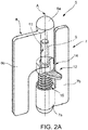
Figure 2A is a perspective view of a hinge connection according to the present invention in a first operation condition; -
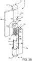
Figure 2B is a perspective view of a hinge connection according to the present invention in a second operation condition; -
Figures 3A to 3C are respective perspective exploded views of a hinge connection according to the present invention in different exploded configurations; -
Figure 4 is a section view about a longitudinal plane of a hinge connection according to the present invention in a first operation configuration; -
Figure 5 is a longitudinal section view of a hinge connection according to the present invention in a second operation configuration; -
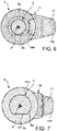
Figure 6 is a transversal section view about plane VI-VI offigure 4 of the hinge connection of the present invention; and -
Figure 7 is a transversal section view about plane VII-VII offigure 4 of the hinge connection of the present invention. -
Figure 1 discloses a vehicle 1, in the present embodiment a work vehicle such as a scraper. Although the invention will be described with respect to such vehicle it is clear that it is not limited thereto. - Vehicle 1 defines, as known, a
body 2 configured to be carried on a carriage 3 movable with respect to the ground.Such body 2 may comprise a panel 4 carried by thebody 2 thanks to anhinge connection 5 according to the present invention. In particular, the panel is connected to thebody 2 thanks to an upper and alower hinge connections 5. - The at least one
hinge connection 5 allows the panel 4 to assume a first operational position, closed, into which it isolate aninner space 6 defined by vehicle's body 2 (not shown) and a second operational position, opened, into which it allows the communication with the environment of such inner space 6 (as shown infigure 1 ). - As depicted in
figures 2A ,2B the hinge connection comprises essentially a first, male,element 7 and a second, female,element 8 configured to cooperate in a rotatably free manner, as per se known, about a rotation axis A. - Indeed, for sake of clarity,
male element 7 can define aprotrusion 9 configured to cooperate at contact with arespective seat 11 realized in thefemale element 8. Theprotrusion 9 defines a shape coupling with the shape of theseat 11, e.g. acylindrical protrusion 9 andseat 11. - According to the proposed embodiment, both the male and
female elements coupling portion protrusion 9 and thehousing 11 and afixing portion - In particular, the
coupling portion fixing portion respective coupling portion coupling portions fixing portions - The
fixing portions body 2 of vehicle 1 and the panel 4 so that relative movement between first andsecond element body 2. For sake of example, thefixing portions male elements 7 are both positioned vertically lower with respect tofemale elements 8. - According to the present invention, the
hinge connection 5 comprises locking means 12 integrated in thehinge connection 5 itself and configured to lock the relative rotation of male andfemale elements female elements - In particular, the locking means 12 comprises a cam coupling between a
cam 14 and a guide define in one between the male andfemale elements elastic means 16 configured to maintain the cam coupling against the one between the male andfemale elements such guide 15. - In particular, in the proposed example, the
cam 14 insist on aguide 15 defined by thefemale element 8 and theelastic means 16 are interposed between themale element 7 and thecam 14 and exert a force against thefemale element 8. - According to the disclosed embodiment, the
cam 14 comprises anannular element 14a housed about theprotrusion 9, in particular defining an inner diameter configured to cooperate at contact with the external surface of theprotrusion 9 and an outer diameter having the same dimension of thecoupling portions female element annular element 14a is axially comprised between the male andfemale elements -
Cam 14 further comprises aprotrusion 14b from an edge of the femaleannular element 14a, preferably parallel to axis A and a flangedportion 14c extending radially fromannular portion 14a, preferably on the opposite side of theprotrusion 14b. The flangedportion 14c furthermore defines agrip portion 17 on its axial surfaces, e.g. thanks to a plurality of grooves realized on such axial surfaces. - The
guide 15 essentially defines at least aslot 18. In the described example, it comprises only aslot 18 realized in a predefined angular position, i.e. in a specific angular position about axis A with respect to a "zero" position corresponding to the opening ofinner space 6 configured to be closed by cover 4. - The
slot 18 is made by a recess starting from the edge of thecentral portion 8a of thefemale element 8 faced to thecam 14.Such slot 18 is opened on such edge and has a shape configured to match with the shape of theprotrusion 14b defined bycam 14. - Advantageously, the
cam 14 is carried byprotrusion 9 thanks to a mechanical coupling, in particular a prismatic coupling, configured to allow only the vertical movement of thecam 14 on theprotrusion 9 about axis A. - Preferably, the
protrusion 9 is divided into two different portions, abase portion 9a and aterminal portion 9b. Thebase portion 9a extends from thecoupling portion 7a and theterminal portion 9b extends from the base portion so that thecoupling portion 7a has a greater diameter than thebase portion 9a which has, in turn, an outer diameter greater than theterminal portion 9b. - The
housing 11 has a diameter configured to cooperate at contact only withterminal portion 9b so that thebase portion 9a defines a vertical stop position on the coupling between male andfemale members - The
base portion 9a has a substantially cylindrical cross-section except for aflat surface 9c realized secant the substantially cylindrical cross-section of thebase portion 9a. Theannular portion 14a of thecam 14 defines an inner shape configured to cooperate at contact with thebase portion 9a, i.e. comprises a flat surface configured to cooperate with theflat surface 9c of thebase portion 9a. Accordingly, it is clear that thecam 14 can slide along axis A on thebase portion 9a but cannot rotate about axis A on this latter because of the anti-rotation effect of flat surfaces coupling as defined above. - Preferably,
elastic means 16 comprises acoil spring 19 radially housed about axis A, in particular aboutbase portion 9a ofprotrusion 9.Coil spring 19 is configured to define a force that maintains thecam 14 againstfemale element 8. - Advantageously, both
male element 7 andcam element 14 defined respectiveannular seat 20 for housing terminal portions ofcoil spring 19. - The operation of the above described
hinge connection 5 according to the present invention is the following. - Making reference to
figures 2A and4 , in such condition the panel 4 is in its opened, i.e. the second operational position. In such configuration, theprotrusion 14b is inserted inslot 18; accordingly, such coupling avoids any possible rotation between the male andfemale elements - When the user wants to close the panel 4, i.e. wants to pass from the second to the first operational position, the user can exert a force F on the
flanged portion 14c of thecam 14, thereby forcing in compression theelastic means 16. The presence of thesurface 9c avoids any rotational movement of thecam 14 aboutbase portion 9a of theprotrusion 9 and the force F is all directed to force in compression the elastic means 16, thereby allowing the sliding ofcam 14 on thebase portion 9a. Accordingly, theprotrusion 14b disengage fromslot 18 and the panel 4 can be closed since thefemale element 8 is again free to rotate with respect to themale element 7. Once rotated for a sufficient angle to avoid a further coupling of theprotrusion 14b withslot 18, thecam 14 will be in contact with the lower edge of thecoupling portion 8a of thefemale element 8. The force ofelastic means 16 will maintain in contact the protrusion14b withslot 18 in a way sufficient to guarantee its sliding which can be useful to dampen the movement of panel 4. - When the user wants to open the panel 4, i.e. wants to pass from the first to the second operational position, it is only necessary to open the panel, thereby moving
female element 8 with respect tomale element 7. Accordingly, theprotrusion 14b will slide on the lower edge of thecentral portion 8a till reachingseat 18 into which will automatically insert thanks to the presence of the force of theelastic means 16. In this way, the male andfemale elements - In view of the foregoing, the advantages of a
hinge connection 5 according to the invention are apparent. - The proposed
hinge connection 5 is simple, integrated into the hinge connection itself and automatically locked when the predetermined angle/angles is/are reached. - Indeed, the proposed
hinge connection 5 foresees few and economic components that does not change the cost of production or the encumbrances of the existing hinge connections. - Since the system is automatically locking, the user cannot forget to secure the panel 4 and, moreover, the unlocking is simple and quick.
- The proposed system can be applied to any existing vehicle 1 and the existing hinge connections can be modified in an economic manner to apply the features of the hinge connection according to the invention.
- It is clear that modifications can be made to the described
hinge connection 5 which do not extend beyond the scope of protection defined by the claims. - For example, the proposed shapes of male and
female elements cam 14, theguide 15 orprotrusion 9 can be varied while maintaining the same purpose. - Furthermore, the respective positioning and coupling of male and
female elements cam 14 and guide 15 or toelastic means 16 may be varied to assume the possible non described alternatives, omitted for sake of brevity. - It is furthermore clear that the
guide 15 can be realized separated by said male orfemale elements cam 14 can be integrated in said male orfemale elements
Claims (15)
- Hinge connection (5) for a panel (4) of a vehicle (1) said hinge connection (5) comprising a male element (7) configured to be connected to one between said panel (4) and said vehicle (1) and a female element (8) configured to be connected to the other between said panel (4) and said vehicle (1), said male element (7) defining a protrusion (9) configured to cooperate at contact with a housing (11) defined in said female element (8) to allow a relative rotation between said female element (8) and said male element (7) about an axis (A),
said hinge connection (5) further comprising locking means (12) configured to lock the relative position between male and female elements (7, 8) when a predetermined relative rotation between the latter has been reached. - Hinge connection according to claim 1, wherein said locking means (12) comprise a cam coupling between said male and female elements (7, 8).
- Hinge connection according to claim 2, wherein said cam coupling is realized about said protrusion (9) and axially comprised between said male and female elements (7, 8).
- Hinge connection according to claim 2 or 3, wherein said cam coupling comprises a cam (14) configured to cooperate at contact with a guide (15), said guide (15) being realized in one between said male and female elements (7, 8).
- Hinge connection according to claim 4, wherein said cam (14) is a separated element with respect to said male and female elements (7, 8).
- Hinge connection according to claim 4 or 5, further comprising elastic means configured to maintain said cam (14) against said guide (15).
- Hinge connection according to any of claims 4 to 6, wherein said guide (15) comprises at least a seat (18) realized in a predefined angular position with respect to said axis (A) .
- Hinge connection according to any of claims 4 to 7, wherein said cam (14) comprises an annular element (14a) arranged to surround said protrusion (9), a protrusion (14b) configured to cooperate with said guide (15) and a flanged portion (14c) defining grip portion (17).
- Hinge connection according to any of claims 4 to 8, wherein said protrusion (9) comprises a base portion (9a) configured to be coupled with said cam (14) to allow only a translational motion along said axis (A) and a terminal portion (9b) extending from said base portion (9a) parallel to said axis (A) and configured to cooperate at contact with said housing (11).
- Hinge connection according to claim 9, wherein the coupling between said base portion (9a) and said cam (14) is a prismatic coupling.
- Hinge connection according to any of claims 6 to 10, wherein said elastic means (16) comprises a coil spring (19) arranged to surround said protrusion (9).
- Hinge connection according to any of claims 9 to 10, wherein said elastic means (16) comprises a coil spring (19) arranged to surround said base portion (9a) of said protrusion (9) .
- Hinge connection according to any of claims 4 to 12, wherein said cam (14) is carried by the one between said male and female elements (7, 8) coupled to said panel (4).
- Hinge connection according to any of the preceding claims, wherein each between said male and female elements (7, 8) comprises a coupling portion (7a, 8a) defining respectively said protrusion (9) and said housing (11) and a fixing portion (7b, 8b) configured to allow the coupling of said male and female elements (7, 8) to respectively said vehicle (1) and said panel (4).
- Vehicle (1) comprising a panel (4) configured to assume at least a first closed position and a second opened position to allow the access to an inner space (6) of said vehicle, said panel (4) being coupled to said vehicle (1) by at least one hinge connection (5) according to any of the preceding claims.
Applications Claiming Priority (1)
| Application Number | Priority Date | Filing Date | Title |
|---|---|---|---|
| IT102020000010885A IT202000010885A1 (en) | 2020-05-13 | 2020-05-13 | HINGED CONNECTION FOR A WORK VEHICLE PANEL |
Publications (1)
| Publication Number | Publication Date |
|---|---|
| EP3910142A1 true EP3910142A1 (en) | 2021-11-17 |
Family
ID=71662281
Family Applications (1)
| Application Number | Title | Priority Date | Filing Date |
|---|---|---|---|
| EP21173726.7A Withdrawn EP3910142A1 (en) | 2020-05-13 | 2021-05-13 | Hinge connection for a panel for a work vehicle |
Country Status (2)
| Country | Link |
|---|---|
| EP (1) | EP3910142A1 (en) |
| IT (1) | IT202000010885A1 (en) |
Citations (4)
| Publication number | Priority date | Publication date | Assignee | Title |
|---|---|---|---|---|
| US1076568A (en) * | 1913-06-13 | 1913-10-21 | Motoichi Furuya | Spring-hinge. |
| DE508865C (en) * | 1930-10-20 | Albert Brugger | Lockable tape for windows and doors | |
| US2362923A (en) * | 1941-12-09 | 1944-11-14 | Norman H Pardoe | Ratchet hinge for vehicle doors |
| US8556330B2 (en) * | 2012-01-13 | 2013-10-15 | Chrysler Group Llc | Removable door with hinge detent |
-
2020
- 2020-05-13 IT IT102020000010885A patent/IT202000010885A1/en unknown
-
2021
- 2021-05-13 EP EP21173726.7A patent/EP3910142A1/en not_active Withdrawn
Patent Citations (4)
| Publication number | Priority date | Publication date | Assignee | Title |
|---|---|---|---|---|
| DE508865C (en) * | 1930-10-20 | Albert Brugger | Lockable tape for windows and doors | |
| US1076568A (en) * | 1913-06-13 | 1913-10-21 | Motoichi Furuya | Spring-hinge. |
| US2362923A (en) * | 1941-12-09 | 1944-11-14 | Norman H Pardoe | Ratchet hinge for vehicle doors |
| US8556330B2 (en) * | 2012-01-13 | 2013-10-15 | Chrysler Group Llc | Removable door with hinge detent |
Also Published As
| Publication number | Publication date |
|---|---|
| IT202000010885A1 (en) | 2021-11-13 |
Similar Documents
| Publication | Publication Date | Title |
|---|---|---|
| EP2268965B1 (en) | Closure for an equipment sub | |
| US10006228B2 (en) | Door latch device for vehicle | |
| EP4174260B1 (en) | Panel lock | |
| CN108269703B (en) | External operating handle | |
| US5158268A (en) | Positioning device | |
| CA2736572A1 (en) | Actuator for operating valves such as diaphragm valves | |
| US11753854B2 (en) | Activation installation | |
| CA2502404A1 (en) | Bayonet latch | |
| US12128757B2 (en) | Lid assembly structure | |
| EP4170121B1 (en) | Covering box and hood for roller elements | |
| US10927572B2 (en) | Motor vehicle door lock | |
| US1189201A (en) | Hinge. | |
| US20050160776A1 (en) | Lock module for motor vehicle door | |
| CN210311870U (en) | Packing box and vehicle | |
| EP4429994B1 (en) | Finger guard | |
| IT202000010885A1 (en) | HINGED CONNECTION FOR A WORK VEHICLE PANEL | |
| US11993969B1 (en) | Hinge | |
| EP4406740B1 (en) | A fill port assembly | |
| WO2011001513A1 (en) | Housing for power conditioner | |
| US11859427B2 (en) | Hinge and method for adjusting a hinge | |
| EP3255229A1 (en) | Auxiliary locking device for sliding doors or hinged doors and the like for applications in motor vehicles | |
| US11505050B2 (en) | Emergency mechanism for lid kinematic device | |
| KR102861638B1 (en) | Open and close apparatus for a tailgate of vehicle | |
| KR101936128B1 (en) | Luggage box for vehicle | |
| KR20090072953A (en) | Handlebar devices for car boards |
Legal Events
| Date | Code | Title | Description |
|---|---|---|---|
| PUAI | Public reference made under article 153(3) epc to a published international application that has entered the european phase |
Free format text: ORIGINAL CODE: 0009012 |
|
| STAA | Information on the status of an ep patent application or granted ep patent |
Free format text: STATUS: THE APPLICATION HAS BEEN PUBLISHED |
|
| AK | Designated contracting states |
Kind code of ref document: A1 Designated state(s): AL AT BE BG CH CY CZ DE DK EE ES FI FR GB GR HR HU IE IS IT LI LT LU LV MC MK MT NL NO PL PT RO RS SE SI SK SM TR |
|
| B565 | Issuance of search results under rule 164(2) epc |
Effective date: 20210915 |
|
| STAA | Information on the status of an ep patent application or granted ep patent |
Free format text: STATUS: REQUEST FOR EXAMINATION WAS MADE |
|
| 17P | Request for examination filed |
Effective date: 20220517 |
|
| RBV | Designated contracting states (corrected) |
Designated state(s): AL AT BE BG CH CY CZ DE DK EE ES FI FR GB GR HR HU IE IS IT LI LT LU LV MC MK MT NL NO PL PT RO RS SE SI SK SM TR |
|
| STAA | Information on the status of an ep patent application or granted ep patent |
Free format text: STATUS: THE APPLICATION IS DEEMED TO BE WITHDRAWN |
|
| 18D | Application deemed to be withdrawn |
Effective date: 20220518 |