EP3910117A2 - Mechanical shower device having sliding temperature regulation, shower having sliding temperature regulation and display module thereof - Google Patents
Mechanical shower device having sliding temperature regulation, shower having sliding temperature regulation and display module thereof Download PDFInfo
- Publication number
- EP3910117A2 EP3910117A2 EP21173658.2A EP21173658A EP3910117A2 EP 3910117 A2 EP3910117 A2 EP 3910117A2 EP 21173658 A EP21173658 A EP 21173658A EP 3910117 A2 EP3910117 A2 EP 3910117A2
- Authority
- EP
- European Patent Office
- Prior art keywords
- water inlet
- light
- temperature regulation
- proportional valve
- shower device
- Prior art date
- Legal status (The legal status is an assumption and is not a legal conclusion. Google has not performed a legal analysis and makes no representation as to the accuracy of the status listed.)
- Withdrawn
Links
Images





Classifications
-
- E—FIXED CONSTRUCTIONS
- E03—WATER SUPPLY; SEWERAGE
- E03C—DOMESTIC PLUMBING INSTALLATIONS FOR FRESH WATER OR WASTE WATER; SINKS
- E03C1/00—Domestic plumbing installations for fresh water or waste water; Sinks
- E03C1/02—Plumbing installations for fresh water
- E03C1/04—Water-basin installations specially adapted to wash-basins or baths
- E03C1/0408—Water installations especially for showers
-
- E—FIXED CONSTRUCTIONS
- E03—WATER SUPPLY; SEWERAGE
- E03C—DOMESTIC PLUMBING INSTALLATIONS FOR FRESH WATER OR WASTE WATER; SINKS
- E03C1/00—Domestic plumbing installations for fresh water or waste water; Sinks
- E03C1/02—Plumbing installations for fresh water
-
- E—FIXED CONSTRUCTIONS
- E03—WATER SUPPLY; SEWERAGE
- E03C—DOMESTIC PLUMBING INSTALLATIONS FOR FRESH WATER OR WASTE WATER; SINKS
- E03C1/00—Domestic plumbing installations for fresh water or waste water; Sinks
- E03C1/02—Plumbing installations for fresh water
- E03C1/021—Devices for positioning or connecting of water supply lines
-
- E—FIXED CONSTRUCTIONS
- E03—WATER SUPPLY; SEWERAGE
- E03C—DOMESTIC PLUMBING INSTALLATIONS FOR FRESH WATER OR WASTE WATER; SINKS
- E03C1/00—Domestic plumbing installations for fresh water or waste water; Sinks
- E03C1/02—Plumbing installations for fresh water
- E03C1/021—Devices for positioning or connecting of water supply lines
- E03C1/023—Devices for positioning or connecting of water supply lines with flow distribution, e.g. diverters
-
- E—FIXED CONSTRUCTIONS
- E03—WATER SUPPLY; SEWERAGE
- E03C—DOMESTIC PLUMBING INSTALLATIONS FOR FRESH WATER OR WASTE WATER; SINKS
- E03C1/00—Domestic plumbing installations for fresh water or waste water; Sinks
- E03C1/02—Plumbing installations for fresh water
- E03C1/04—Water-basin installations specially adapted to wash-basins or baths
- E03C1/0412—Constructional or functional features of the faucet handle
-
- F—MECHANICAL ENGINEERING; LIGHTING; HEATING; WEAPONS; BLASTING
- F16—ENGINEERING ELEMENTS AND UNITS; GENERAL MEASURES FOR PRODUCING AND MAINTAINING EFFECTIVE FUNCTIONING OF MACHINES OR INSTALLATIONS; THERMAL INSULATION IN GENERAL
- F16K—VALVES; TAPS; COCKS; ACTUATING-FLOATS; DEVICES FOR VENTING OR AERATING
- F16K11/00—Multiple-way valves, e.g. mixing valves; Pipe fittings incorporating such valves
- F16K11/02—Multiple-way valves, e.g. mixing valves; Pipe fittings incorporating such valves with all movable sealing faces moving as one unit
-
- G—PHYSICS
- G09—EDUCATION; CRYPTOGRAPHY; DISPLAY; ADVERTISING; SEALS
- G09F—DISPLAYING; ADVERTISING; SIGNS; LABELS OR NAME-PLATES; SEALS
- G09F9/00—Indicating arrangements for variable information in which the information is built-up on a support by selection or combination of individual elements
- G09F9/30—Indicating arrangements for variable information in which the information is built-up on a support by selection or combination of individual elements in which the desired character or characters are formed by combining individual elements
-
- E—FIXED CONSTRUCTIONS
- E03—WATER SUPPLY; SEWERAGE
- E03C—DOMESTIC PLUMBING INSTALLATIONS FOR FRESH WATER OR WASTE WATER; SINKS
- E03C1/00—Domestic plumbing installations for fresh water or waste water; Sinks
- E03C1/02—Plumbing installations for fresh water
- E03C1/04—Water-basin installations specially adapted to wash-basins or baths
- E03C2001/0418—Water-basin installations specially adapted to wash-basins or baths having temperature indicating means
Definitions
- the present disclosure relates to sanitary wares, in particular relates to a shower device.
- a shower device is a device used to control a combined shower head. It has functions for switching water outlet terminals, opening and stopping water and temperature adjustment.
- This kind of shower device has evolved from a single handle to an operation box along with increase of shower functions, and its operation convenience and intuitiveness have been greatly improved.
- this kind of operation box often requires a large number of electronic components to achieve switching, temperature adjustment, etc., a cost is relatively high, waterproof requirements are also relatively high, which causes the cost of this kind of shower box to remain high, is usually only assembled to high-end products and cannot be used by more people.
- the present disclosure provides a mechanical shower device having sliding temperature regulation, which adopts a pure machine structure to realize sliding temperature regulation, a cost is relatively low, and an operation method is relatively intuitive.
- a mechanical shower device having sliding temperature regulation, which comprising a cold water inlet, a hot water inlet, a switching valve and a toggle button;
- the switching valve comprises a water inlet;
- the toggle button is disposed on a surface of the shower device and is configured to be toggled along a length direction of the shower device;
- the water inlet When the toggle button is in a middle position, the water inlet is in communication with the cold water inlet and the hot water inlet at the same time; when the toggle button moves leftward or rightward relative to the middle position, a water flowing area between the water inlet and one of the cold water inlet and hot water inlet gradually decreases, and a water flowing area between the water inlet and the other one gradually increases.
- the switching valve comprises a valve body and a switching shaft operatively disposed on the valve body; one end of the switching shaft is operatively connected to the toggle button by a linkage member.
- a side wall of the valve body is disposed with the water inlet.
- the linkage member is a swing shaft, one end of the swing shaft is operatively connected to the toggle button, and the other end is rotatably connected to the one end of the switching shaft.
- the water inlet when the toggle button is in the middle position, the water inlet is in communication with the cold water inlet and the hot water inlet at the same time; when the toggle button moves to two end positions, the water inlet is merely in communication with the cold water inlet or the hot water inlet.
- the switching valve comprises a cold water proportional valve and a hot water proportional valve, and the water inlet is in communication with water outlets of the cold water proportional valve and the hot water proportional valve.
- the cold water proportional valve and the hot water proportional valve respectively comprise a pole plug configured to open and close the water outlets; pole plugs of the cold water proportional valve and the hot water proportional valve are connected by an adjusting rod.
- a middle portion of the adjusting rod is a swing fulcrum; when the adjusting rod is in a horizontal position, the water outlets of the cold water proportional valve and the hot water proportional valve are respectively opened by the pole plugs; when the swing fulcrum swings towards the cold water proportional valve or the hot water proportional valve, the water outlets of the cold water proportional valve or the hot water proportional valve are gradually closed by the pole plugs.
- a push force generated between the toggle button and the adjusting rod pushes the adjusting rod to swing towards the cold water proportional valve or the hot water proportional valve.
- a side of the adjusting rod facing the toggle button extends to define an inclined surface from the fulcrum to the two sides.
- the adjusting rod is operatively connected to the toggle button along a moving direction of the toggle; when the toggle button moves leftward or rightward relative to the middle position, a push force generated between the adjusting rod and the pole plugs pushes the pole plugs to gradually close the water outlets of the cold water proportional valve or the hot water proportional valve.
- a display module which further comprises a light-emitting module, a lamp holder and a panel; the light-emitting module and the panel are respectively disposed on two sides of the lamp holder along a thickness direction of the lamp holder; a side of the lamp holder facing the light-emitting module is divided into a plurality of grids along a sliding direction for temperature regulation, surfaces of the grids along the thickness direction of the lamp holder are light-transmitting surfaces, and the light-emitting module is disposed with light-emitting units corresponding to the grids one-to-one; the panel is a transparent panel, a side of which facing the lamp holder is covered with a light-transmitting layer, and a side of the light-transmitting layer facing the lamp holder is disposed with opaque numbers corresponding to part of the grids one-to-one.
- the number of grids is N, wherein N-1 corresponds to the opaque numbers one to one; when temperature of outflowing water is greater than the maximum value of the opaque numbers, a light-emitting unit corresponding to the remaining grid flashes and emits light.
- a side of the panel facing the light-transmitting layer is disposed with water outlet terminal indicator icons and heating and cooling indicator icons.
- the present disclosure further discloses a display module of a shower device having sliding temperature regulation, which comprises a light-emitting module, a lamp holder and a panel; the light-emitting module and the panel are respectively disposed on two sides of the lamp holder along a thickness direction of the lamp holder; a side of the lamp holder facing the light-emitting module is divided into a plurality of grids along a sliding direction for temperature regulation, surfaces of the grids along the thickness direction of the lamp holder are light-transmitting surfaces, and the light-emitting module is disposed with light-emitting units corresponding to the grids one-to-one;
- the panel is a transparent panel, a side of which facing the lamp holder is covered with a light-transmitting layer, and a side of the light-transmitting layer facing the lamp holder is disposed with opaque numbers corresponding to part of the grids one-to-one.
- the number of grids is N, wherein N-1 corresponds to the opaque numbers one to one; when temperature of outflowing water is greater than the maximum value of the opaque numbers, a light-emitting unit corresponding to the remaining grid blinks and emits light.
- a side of the panel facing the light-transmitting layer is disposed with water outlet terminal indicator icons and heating and cooling indicator icons.
- the present disclosure further discloses a shower having sliding temperature regulation, which comprises the display module.
- the present disclosure provides a mechanical shower device having sliding temperature regulation, which drives the water inlet of the valve body to be in communication with one or two of the cold water inlet and the hot water inlet by the toggle button, thereby the temperature of the outflowing water is changed.
- This temperature regulation method can increase or decrease the temperature due to toggling the toggle button in one direction, which is very intuitive, and the cost of the pure machine temperature regulation method is relatively low.
- this operation has no relationship with water pressure. A required force for user operation is the same under any water pressure, and the operation consistency is better.
- this embodiment discloses a mechanical shower device having sliding temperature regulation, which comprises a cold water inlet 1, a hot water inlet 2, a switching valve 3 and a toggle button 4.
- the switching valve 3 comprises a water inlet 34.
- the toggle button 4 is disposed on a surface of the shower device and is configured to be toggled along a length direction of the shower device.
- the toggle button 4 drives the water inlet 34 to be merely in communication with the cold water inlet 1, to be in communication with the cold water inlet 1 and the hot water inlet 2 at the same time, or to be merely in communication with the hot water inlet 2.
- the toggle button 4 drives the water inlet 34 of a valve body to be connected to one or two of the cold water inlet 1 and the hot water inlet 2 to adjust a temperature of outflowing water.
- This temperature regulation method can increase or decrease the temperature by toggling the toggle button 4 in one direction, which is very intuitive, and a cost of the pure machine temperature regulation method is relatively low.
- the toggle button 4 is disposed on the surface of the shower device, it is also very convenient to operate the toggle button 4 by the user.
- the switching valve 3 comprises the valve body 31 and a switching shaft 32 operatively disposed on the valve body 31.
- One end of the switching shaft 32 is operatively connected to the toggle button 4 by a linkage member 33.
- the linkage member 33 is a swing shaft, one end of which is operatively connected to the toggle button 4, and the other end is rotatably connected to the one end of the switching shaft 32.
- the switching shaft 32 swings about a fulcrum that is rotatably connected to the switching shaft 32, and pushing force or pulling force generated due to the swinging will push or pull the switching shaft 32.
- the valve body 31 is driven to move.
- the water inlet 34 is merely in communication with the cold water inlet 1, in communication with the cold water inlet 1 and the hot water inlet 2 at the same time, or merely in communication with the hot water inlet 2.
- a side wall of the valve body 31 is disposed with the water inlet 34.
- the water inlet 34 is in communication with the cold water inlet 1 and the hot water inlet 2 at the same time.
- the water inlet 34 is merely in communication with the cold water inlet 1 or the hot water inlet 2.
- the toggle button 4 is in the middle position, the cold water inlet 1 and the hot water inlet 2 are respectively in communication with the water inlet 34, and the outflowing water is mixed water of cold water and hot water.
- this embodiment differs from Embodiment 1 in that the switching valve 3 comprises a cold water proportional valve 35 and a hot water proportional valve 36, and the water inlet 34 is in communication with water outlets of the cold water proportional valve 35 and the hot water proportional valve 36. Water temperature regulation can also be achieved due to adjusting water flowing areas of the water outlets of the cold water proportional valve 35 and the hot water proportional valve 36.
- the cold water proportional valve 35 and the hot water proportional valve 36 respectively comprise a pole plug 37 configured to open and close the water outlets, so that the water flowing areas of the water outlets of the cold water proportional valve 35 and the hot water proportional valve 36 change accordingly when the toggle button 4 is toggled.
- Pole plugs 37 of the cold water proportional valve 35 and the hot water proportional valve 36 are connected by an adjusting rod 38.
- a middle portion of the adjusting rod 38 is a swing fulcrum.
- the pole plugs 37 respectively open the water outlets of the cold water proportional valve 35 and the hot water proportional valve 36.
- the adjusting rod 38 swings towards the cold water proportional valve 35 or the hot water proportional valve 36, the adjusting rod 38 pushes the pole plugs 37 to gradually close the water outlets of the cold water proportional valve 35 or the hot water proportional valve 36.
- a push force generated between the toggle button 4 and the adjustment rod 38 pushes the adjustment rod 38 to swing towards the cold water proportional valve 35 or the hot water proportional valve 36, so that the toggle button 4 drives the adjustment rod 38 to swing.
- a side of the adjusting rod 38 facing the toggle button 4 extends to define an inclined surface from the fulcrum to two sides.
- this embodiment differs from Embodiment 1 in that the switching valve 3 comprises a cold water proportional valve 35 and a hot water proportional valve 36, and the water inlet 34 is in communication with water outlets of the cold water proportional valve 35 and the hot water proportional valve 36. Water temperature regulation can also be achieved due to adjusting water flowing areas of the water outlets of the cold water proportional valve 35 and the hot water proportional valve 36.
- the cold water proportional valve 35 and the hot water proportional valve 36 respectively comprise a pole plug 37 configured to open and close the water outlets, so that the water flowing areas of the water outlets of the cold water proportional valve 35 and the hot water proportional valve 36 change accordingly when the toggle button 4 is toggled.
- Pole plugs 37 of the cold water proportional valve 35 and the hot water proportional valve 36 are connected by an adjusting rod 38
- the adjusting rod 38 is operatively connected to the toggle 4 along a moving direction of the toggle 4, so that the adjusting rod 38 drives the pole plugs 37 to change and adjust water flowing areas of the water outlets of the cold water proportional valve 35 and the hot water proportional valve 36.
- the toggle button 4 moves leftward or rightward relative to a middle position, a push force generated between the adjusting rod 38 and the plug 37 pushes the pole plug 37 to close the water outlets of the cold water proportional valve 35 or hot water proportional valve 36.
- this embodiment further provides a display module of the mechanical shower device having sliding temperature regulation in Embodiments 1- 3, the display module comprises a light-emitting module 51, a lamp holder 52 and a panel 53.
- the light-emitting module 51 and the panel 53 are respectively disposed on two sides of the lamp holder 52 along a thickness direction of the lamp holder.
- a side of the lamp holder 52 facing the light-emitting module 51 is divided into a plurality of grids 521 along a sliding direction for temperature regulation, surfaces of the grids 521 along the thickness direction of the lamp holder 52 are light-transmitting surfaces, and the light-emitting module 51 is disposed with light-emitting units 511 corresponding to the grids 521 one-to-one.
- the panel 53 is a transparent panel, and a side of which facing the lamp holder 52 is covered with a light-transmitting layer. A side of the light-transmitting layer facing the lamp holder 20 is disposed with opaque numbers 531 corresponding to part of the grids one-to-one.
- a temperature sensor when the user uses the toggle button 4 to adjust the temperature, a temperature sensor can feel temperature change of the temperature of the outflowing water and send a detection value to a main control chip, and the main control chip lights up a corresponding light-emitting unit 511 according to the temperature, light emitted by the light-emitting unit 511 is blocked by ribs around the grids 521 and is emitted from the light-transmitting surfaces of the grids 521, the emitted light is illuminated to the panel 53 through the light-transmitting layer, so that the panel 53 defines an illuminated area with the same shape as the grid 521. For example, if the grid 521 is rectangular, a rectangular area on the panel 53 is illuminated. However, the number 531 is opaque, so there will be a black or gray number displayed on this rectangular area. The user can then know a current temperature of the outflowing water.
- the light-transmitting layer is a white coating screen-printed on the panel 53, and the number 531 is further screen-printed on the light-transmitting layer. Therefore, when there is no light illuminated on the panel 53 from a rear side, the panel 53 is pure white when viewed from a front side, and an integrity is better.
- the number of grids 521 is N, wherein N-1 corresponds to the opaque numbers 531 one-to-one.
- N-1 corresponds to the opaque numbers 531 one-to-one.
- a side of the panel 53 facing away from the light-transmitting layer is disposed with water outlet terminal indicator icons 533 and heating and cooling indicator icons 532.
- the heating and cooling indicator icons 532 are respectively red and blue
- the toggle button 4 is disposed a junction between blue and red.
- the water outlet terminal indicator icons 533 comprises three position icons for a hand shower, a top shower and water off. The icon corresponds to positions of the three icons for the hand shower, the top shower and the water off.
- the water outlet terminal indicator icons 533 and the heating and cooling indicator icons 532 are disposed on the side of the panel 53 facing the light-transmitting layer, even in case there is no light illuminated to the panel 53 from the rear side, the water outlet terminal indicator icons 533 and the heating and cooling indicator icons 532 can also be observed from the front side of the panel, so that the user can observe the water outlet indicator icons 533 and the heating and cooling indicator icons 532 before showering.
- the abovementioned display module which is applied to the mechanical shower device having sliding temperature regulation of Embodiments 1-3, can also be widely applied to other shower devices having sliding temperature regulation. However, it is not limited to this, and will not be further described here.
- the invention may be summarized as follows:
- the present disclosure discloses a mechanical shower device having sliding temperature regulation, which comprising a cold water inlet, a hot water inlet, a switching valve and a toggle button; the switching valve comprises a water inlet; the toggle button is disposed on a surface of the shower device and is configured to be toggled along a length direction of the shower device; when the toggle button is in a middle position, the water inlet is in communication with the cold water inlet and the hot water inlet at the same time; when the toggle button moves leftward or rightward relative to the middle position, a water flowing area between the water inlet and one of the cold water inlet and hot water inlet gradually decreases, and a water flowing area between the water inlet and the other one gradually increases.
- the mechanical shower device having sliding temperature regulation adopts a pure machine structure to realize sliding temperature regulation, a cost is relatively low, and an operation method is relatively intuitive.
- a mechanical shower device having sliding temperature regulation characterized in that: which comprising a cold water inlet, a hot water inlet, a switching valve and a toggle button; the switching valve comprises a water inlet; the toggle button is disposed on a surface of the shower device and is configured to be toggled along a length direction of the shower device; When the toggle button is in a middle position, the water inlet is in communication with the cold water inlet and the hot water inlet at the same time; when the toggle button moves leftward or rightward relative to the middle position, a water flowing area between the water inlet and one of the cold water inlet and hot water inlet gradually decreases, and a water flowing area between the water inlet and the other one gradually increases.
Landscapes
- Engineering & Computer Science (AREA)
- Health & Medical Sciences (AREA)
- Life Sciences & Earth Sciences (AREA)
- Hydrology & Water Resources (AREA)
- Public Health (AREA)
- Water Supply & Treatment (AREA)
- General Engineering & Computer Science (AREA)
- General Physics & Mathematics (AREA)
- Theoretical Computer Science (AREA)
- Physics & Mathematics (AREA)
- Mechanical Engineering (AREA)
- Bathtubs, Showers, And Their Attachments (AREA)
- Domestic Plumbing Installations (AREA)
Abstract
Description
- The present disclosure relates to sanitary wares, in particular relates to a shower device.
- A shower device is a device used to control a combined shower head. It has functions for switching water outlet terminals, opening and stopping water and temperature adjustment. This kind of shower device has evolved from a single handle to an operation box along with increase of shower functions, and its operation convenience and intuitiveness have been greatly improved. However, this kind of operation box often requires a large number of electronic components to achieve switching, temperature adjustment, etc., a cost is relatively high, waterproof requirements are also relatively high, which causes the cost of this kind of shower box to remain high, is usually only assembled to high-end products and cannot be used by more people.
- The present disclosure provides a mechanical shower device having sliding temperature regulation, which adopts a pure machine structure to realize sliding temperature regulation, a cost is relatively low, and an operation method is relatively intuitive.
- In order to solve the technical problems, the present disclosure discloses a mechanical shower device having sliding temperature regulation, which comprising a cold water inlet, a hot water inlet, a switching valve and a toggle button; the switching valve comprises a water inlet; the toggle button is disposed on a surface of the shower device and is configured to be toggled along a length direction of the shower device;
- When the toggle button is in a middle position, the water inlet is in communication with the cold water inlet and the hot water inlet at the same time; when the toggle button moves leftward or rightward relative to the middle position, a water flowing area between the water inlet and one of the cold water inlet and hot water inlet gradually decreases, and a water flowing area between the water inlet and the other one gradually increases.
- In a preferred embodiment, the switching valve comprises a valve body and a switching shaft operatively disposed on the valve body; one end of the switching shaft is operatively connected to the toggle button by a linkage member.
- In a preferred embodiment, a side wall of the valve body is disposed with the water inlet.
- In a preferred embodiment, the linkage member is a swing shaft, one end of the swing shaft is operatively connected to the toggle button, and the other end is rotatably connected to the one end of the switching shaft.
- In a preferred embodiment, when the toggle button is in the middle position, the water inlet is in communication with the cold water inlet and the hot water inlet at the same time; when the toggle button moves to two end positions, the water inlet is merely in communication with the cold water inlet or the hot water inlet.
- In a preferred embodiment, the switching valve comprises a cold water proportional valve and a hot water proportional valve, and the water inlet is in communication with water outlets of the cold water proportional valve and the hot water proportional valve.
- In a preferred embodiment, the cold water proportional valve and the hot water proportional valve respectively comprise a pole plug configured to open and close the water outlets; pole plugs of the cold water proportional valve and the hot water proportional valve are connected by an adjusting rod.
- In a preferred embodiment, a middle portion of the adjusting rod is a swing fulcrum; when the adjusting rod is in a horizontal position, the water outlets of the cold water proportional valve and the hot water proportional valve are respectively opened by the pole plugs; when the swing fulcrum swings towards the cold water proportional valve or the hot water proportional valve, the water outlets of the cold water proportional valve or the hot water proportional valve are gradually closed by the pole plugs.
- In a preferred embodiment, when the toggle button moves leftward or rightward relative to the fulcrum, a push force generated between the toggle button and the adjusting rod pushes the adjusting rod to swing towards the cold water proportional valve or the hot water proportional valve.
- In a preferred embodiment, a side of the adjusting rod facing the toggle button extends to define an inclined surface from the fulcrum to the two sides.
- In a preferred embodiment, the adjusting rod is operatively connected to the toggle button along a moving direction of the toggle; when the toggle button moves leftward or rightward relative to the middle position, a push force generated between the adjusting rod and the pole plugs pushes the pole plugs to gradually close the water outlets of the cold water proportional valve or the hot water proportional valve.
- In a preferred embodiment, which further comprises a display module, which further comprises a light-emitting module, a lamp holder and a panel; the light-emitting module and the panel are respectively disposed on two sides of the lamp holder along a thickness direction of the lamp holder; a side of the lamp holder facing the light-emitting module is divided into a plurality of grids along a sliding direction for temperature regulation, surfaces of the grids along the thickness direction of the lamp holder are light-transmitting surfaces, and the light-emitting module is disposed with light-emitting units corresponding to the grids one-to-one;
the panel is a transparent panel, a side of which facing the lamp holder is covered with a light-transmitting layer, and a side of the light-transmitting layer facing the lamp holder is disposed with opaque numbers corresponding to part of the grids one-to-one. - In a preferred embodiment, the number of grids is N, wherein N-1 corresponds to the opaque numbers one to one; when temperature of outflowing water is greater than the maximum value of the opaque numbers, a light-emitting unit corresponding to the remaining grid flashes and emits light.
- In a preferred embodiment, a side of the panel facing the light-transmitting layer is disposed with water outlet terminal indicator icons and heating and cooling indicator icons.
- The present disclosure further discloses a display module of a shower device having sliding temperature regulation, which comprises a light-emitting module, a lamp holder and a panel; the light-emitting module and the panel are respectively disposed on two sides of the lamp holder along a thickness direction of the lamp holder; a side of the lamp holder facing the light-emitting module is divided into a plurality of grids along a sliding direction for temperature regulation, surfaces of the grids along the thickness direction of the lamp holder are light-transmitting surfaces, and the light-emitting module is disposed with light-emitting units corresponding to the grids one-to-one;
- the panel is a transparent panel, a side of which facing the lamp holder is covered with a light-transmitting layer, and a side of the light-transmitting layer facing the lamp holder is disposed with opaque numbers corresponding to part of the grids one-to-one.
- In a preferred embodiment, the number of grids is N, wherein N-1 corresponds to the opaque numbers one to one; when temperature of outflowing water is greater than the maximum value of the opaque numbers, a light-emitting unit corresponding to the remaining grid blinks and emits light.
- In a preferred embodiment, a side of the panel facing the light-transmitting layer is disposed with water outlet terminal indicator icons and heating and cooling indicator icons.
- The present disclosure further discloses a shower having sliding temperature regulation, which comprises the display module.
- Compared with the existing techniques, the technical solution has the following advantages.
- The present disclosure provides a mechanical shower device having sliding temperature regulation, which drives the water inlet of the valve body to be in communication with one or two of the cold water inlet and the hot water inlet by the toggle button, thereby the temperature of the outflowing water is changed. This temperature regulation method can increase or decrease the temperature due to toggling the toggle button in one direction, which is very intuitive, and the cost of the pure machine temperature regulation method is relatively low. In addition, this operation has no relationship with water pressure. A required force for user operation is the same under any water pressure, and the operation consistency is better.
-
-
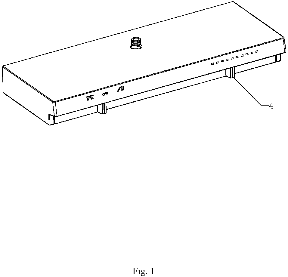
Fig. 1 illustrates a perspective view ofEmbodiment 1 of the present disclosure; -
Fig. 2 illustrates a cross-sectional view ofEmbodiment 1 of the present disclosure; -
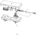
Fig. 3 illustrates an exploded view ofEmbodiment 1 of the present disclosure; -
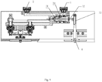
Figs. 4-6 illustrate schematic views of usage states ofEmbodiment 1 of the present disclosure; -
Fig. 7 illustrates a cross-sectional view ofEmbodiment 2 of the present disclosure; -
Fig. 8 illustrates a cross-sectional view ofEmbodiment 3 of the present disclosure; -
Fig. 9 illustrates a schematic view of a display module ofEmbodiment 4 of the present disclosure; -
Fig. 10 illustrates a schematic view of the display module ofEmbodiment 4 of the present disclosure when a temperature of outflowing water is 30 °C; -
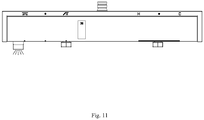
Fig. 11 illustrates a schematic view of the display module inEmbodiment 4 of the present disclosure when the temperature of the outflowing water is 39 °C; -
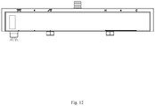
Fig. 12 illustrates a schematic view of the display module ofEmbodiment 4 of the present disclosure when the temperature of the outflowing water is relatively high. - The present disclosure will be further described below in combination with the accompanying drawings and embodiments.
- Referring to
Figs. 1-6 , this embodiment discloses a mechanical shower device having sliding temperature regulation, which comprises acold water inlet 1, ahot water inlet 2, aswitching valve 3 and atoggle button 4. Theswitching valve 3 comprises awater inlet 34. Thetoggle button 4 is disposed on a surface of the shower device and is configured to be toggled along a length direction of the shower device. - When the
toggle button 4 is toggled, thetoggle button 4 drives thewater inlet 34 to be merely in communication with thecold water inlet 1, to be in communication with thecold water inlet 1 and thehot water inlet 2 at the same time, or to be merely in communication with thehot water inlet 2. - In the mechanical shower device having sliding temperature regulation, the
toggle button 4 drives thewater inlet 34 of a valve body to be connected to one or two of thecold water inlet 1 and thehot water inlet 2 to adjust a temperature of outflowing water. This temperature regulation method can increase or decrease the temperature by toggling thetoggle button 4 in one direction, which is very intuitive, and a cost of the pure machine temperature regulation method is relatively low. Moreover, thetoggle button 4 is disposed on the surface of the shower device, it is also very convenient to operate thetoggle button 4 by the user. - In this embodiment, in order to achieve a temperature regulation operation, the
switching valve 3 comprises thevalve body 31 and aswitching shaft 32 operatively disposed on thevalve body 31. One end of theswitching shaft 32 is operatively connected to thetoggle button 4 by alinkage member 33. In this embodiment, thelinkage member 33 is a swing shaft, one end of which is operatively connected to thetoggle button 4, and the other end is rotatably connected to the one end of theswitching shaft 32. In this way, when thetoggle button 4 moves, the switchingshaft 32 swings about a fulcrum that is rotatably connected to theswitching shaft 32, and pushing force or pulling force generated due to the swinging will push or pull theswitching shaft 32. When theswitching shaft 32 moves, thevalve body 31 is driven to move. When thevalve body 31 moves, thewater inlet 34 is merely in communication with thecold water inlet 1, in communication with thecold water inlet 1 and the hot water inlet 2 at the same time, or merely in communication with thehot water inlet 2. - In this embodiment, a side wall of the
valve body 31 is disposed with thewater inlet 34. In a detailed description, when thetoggle button 4 is in a middle position, thewater inlet 34 is in communication with thecold water inlet 1 and thehot water inlet 2 at the same time. When thetoggle button 4 moves to two ends, thewater inlet 34 is merely in communication with thecold water inlet 1 or thehot water inlet 2. In this way, when thetoggle button 4 is in the middle position, thecold water inlet 1 and thehot water inlet 2 are respectively in communication with thewater inlet 34, and the outflowing water is mixed water of cold water and hot water. When thetoggle button 4 moves leftward relative to the middle position, a water flowing area between thewater inlet 34 and thehot water inlet 2 becomes larger, and a water flowing area between thewater inlet 34 and thecold water inlet 1 becomes smaller. When thetoggle button 4 moves rightward relative to the middle position, the water passage area between thewater inlet 34 and thecold water inlet 1 becomes larger, and the water passage area between thewater inlet 34 and thehot water inlet 2 becomes smaller. In this way, stepless adjustment of water temperature is achieved. - Referring to
Fig. 7 , this embodiment differs fromEmbodiment 1 in that the switchingvalve 3 comprises a cold waterproportional valve 35 and a hot waterproportional valve 36, and thewater inlet 34 is in communication with water outlets of the cold waterproportional valve 35 and the hot waterproportional valve 36. Water temperature regulation can also be achieved due to adjusting water flowing areas of the water outlets of the cold waterproportional valve 35 and the hot waterproportional valve 36. - The cold water
proportional valve 35 and the hot waterproportional valve 36 respectively comprise apole plug 37 configured to open and close the water outlets, so that the water flowing areas of the water outlets of the cold waterproportional valve 35 and the hot waterproportional valve 36 change accordingly when thetoggle button 4 is toggled. Pole plugs 37 of the cold waterproportional valve 35 and the hot waterproportional valve 36 are connected by an adjustingrod 38. - In this embodiment, a middle portion of the adjusting
rod 38 is a swing fulcrum. When the adjustingrod 38 is in a horizontal position, the pole plugs 37 respectively open the water outlets of the cold waterproportional valve 35 and the hot waterproportional valve 36. When the adjustingrod 38 swings towards the cold waterproportional valve 35 or the hot waterproportional valve 36, the adjustingrod 38 pushes the pole plugs 37 to gradually close the water outlets of the cold waterproportional valve 35 or the hot waterproportional valve 36. - When the
toggle button 4 move leftward or rightward relative to the fulcrum, a push force generated between thetoggle button 4 and theadjustment rod 38 pushes theadjustment rod 38 to swing towards the cold waterproportional valve 35 or the hot waterproportional valve 36, so that thetoggle button 4 drives theadjustment rod 38 to swing. In a detailed description, a side of the adjustingrod 38 facing thetoggle button 4 extends to define an inclined surface from the fulcrum to two sides. - Referring to
Fig. 8 , this embodiment differs fromEmbodiment 1 in that the switchingvalve 3 comprises a cold waterproportional valve 35 and a hot waterproportional valve 36, and thewater inlet 34 is in communication with water outlets of the cold waterproportional valve 35 and the hot waterproportional valve 36. Water temperature regulation can also be achieved due to adjusting water flowing areas of the water outlets of the cold waterproportional valve 35 and the hot waterproportional valve 36. - The cold water
proportional valve 35 and the hot waterproportional valve 36 respectively comprise apole plug 37 configured to open and close the water outlets, so that the water flowing areas of the water outlets of the cold waterproportional valve 35 and the hot waterproportional valve 36 change accordingly when thetoggle button 4 is toggled. Pole plugs 37 of the cold waterproportional valve 35 and the hot waterproportional valve 36 are connected by an adjustingrod 38 - In this Embodiment, the adjusting
rod 38 is operatively connected to thetoggle 4 along a moving direction of thetoggle 4, so that the adjustingrod 38 drives the pole plugs 37 to change and adjust water flowing areas of the water outlets of the cold waterproportional valve 35 and the hot waterproportional valve 36. When thetoggle button 4 moves leftward or rightward relative to a middle position, a push force generated between the adjustingrod 38 and theplug 37 pushes thepole plug 37 to close the water outlets of the cold waterproportional valve 35 or hot waterproportional valve 36. - Referring to
Figs. 9-12 , this embodiment further provides a display module of the mechanical shower device having sliding temperature regulation in Embodiments 1- 3, the display module comprises a light-emittingmodule 51, alamp holder 52 and apanel 53. The light-emittingmodule 51 and thepanel 53 are respectively disposed on two sides of thelamp holder 52 along a thickness direction of the lamp holder. A side of thelamp holder 52 facing the light-emittingmodule 51 is divided into a plurality ofgrids 521 along a sliding direction for temperature regulation, surfaces of thegrids 521 along the thickness direction of thelamp holder 52 are light-transmitting surfaces, and the light-emittingmodule 51 is disposed with light-emittingunits 511 corresponding to thegrids 521 one-to-one. - The
panel 53 is a transparent panel, and a side of which facing thelamp holder 52 is covered with a light-transmitting layer. A side of the light-transmitting layer facing the lamp holder 20 is disposed withopaque numbers 531 corresponding to part of the grids one-to-one. - Through the abovementioned design, when the user uses the
toggle button 4 to adjust the temperature, a temperature sensor can feel temperature change of the temperature of the outflowing water and send a detection value to a main control chip, and the main control chip lights up a corresponding light-emittingunit 511 according to the temperature, light emitted by the light-emittingunit 511 is blocked by ribs around thegrids 521 and is emitted from the light-transmitting surfaces of thegrids 521, the emitted light is illuminated to thepanel 53 through the light-transmitting layer, so that thepanel 53 defines an illuminated area with the same shape as thegrid 521. For example, if thegrid 521 is rectangular, a rectangular area on thepanel 53 is illuminated. However, thenumber 531 is opaque, so there will be a black or gray number displayed on this rectangular area. The user can then know a current temperature of the outflowing water. - In this embodiment, the light-transmitting layer is a white coating screen-printed on the
panel 53, and thenumber 531 is further screen-printed on the light-transmitting layer. Therefore, when there is no light illuminated on thepanel 53 from a rear side, thepanel 53 is pure white when viewed from a front side, and an integrity is better. - In this embodiment, the number of
grids 521 is N, wherein N-1 corresponds to theopaque numbers 531 one-to-one. When the temperature of the outflowing water is greater than the maximum value of the opaque numbers, a light-emittingunit 511 corresponding to the remaininggrid 521 blinks and emits light. A purpose of this design is to remind consumers to lower down water temperature due to the blinking of thegrid 521 when the temperature of the outflowing water is too high, so that a harm applied to a body of the consumer due to a high temperature is avoided. - In addition, in order to further facilitate the user to adjust the temperature and to switch a water outlet terminal, a side of the
panel 53 facing away from the light-transmitting layer is disposed with water outletterminal indicator icons 533 and heating andcooling indicator icons 532. Wherein the heating andcooling indicator icons 532 are respectively red and blue, and thetoggle button 4 is disposed a junction between blue and red. When being toggled towards a blue part, the temperature is lowered down, and vice versa, the operation is clear. The water outletterminal indicator icons 533 comprises three position icons for a hand shower, a top shower and water off. The icon corresponds to positions of the three icons for the hand shower, the top shower and the water off. When the toggle button is toggled to a corresponding icon, a corresponding outlet terminal is switched. The water outletterminal indicator icons 533 and the heating andcooling indicator icons 532 are disposed on the side of thepanel 53 facing the light-transmitting layer, even in case there is no light illuminated to thepanel 53 from the rear side, the water outletterminal indicator icons 533 and the heating andcooling indicator icons 532 can also be observed from the front side of the panel, so that the user can observe the wateroutlet indicator icons 533 and the heating andcooling indicator icons 532 before showering. - The abovementioned display module, which is applied to the mechanical shower device having sliding temperature regulation of Embodiments 1-3, can also be widely applied to other shower devices having sliding temperature regulation. However, it is not limited to this, and will not be further described here.
- The invention may be summarized as follows: The present disclosure discloses a mechanical shower device having sliding temperature regulation, which comprising a cold water inlet, a hot water inlet, a switching valve and a toggle button; the switching valve comprises a water inlet; the toggle button is disposed on a surface of the shower device and is configured to be toggled along a length direction of the shower device; when the toggle button is in a middle position, the water inlet is in communication with the cold water inlet and the hot water inlet at the same time; when the toggle button moves leftward or rightward relative to the middle position, a water flowing area between the water inlet and one of the cold water inlet and hot water inlet gradually decreases, and a water flowing area between the water inlet and the other one gradually increases. The mechanical shower device having sliding temperature regulation adopts a pure machine structure to realize sliding temperature regulation, a cost is relatively low, and an operation method is relatively intuitive.
- The invention may also be summarized as follows: 1. A mechanical shower device having sliding temperature regulation, characterized in that: which comprising a cold water inlet, a hot water inlet, a switching valve and a toggle button; the switching valve comprises a water inlet; the toggle button is disposed on a surface of the shower device and is configured to be toggled along a length direction of the shower device;
When the toggle button is in a middle position, the water inlet is in communication with the cold water inlet and the hot water inlet at the same time; when the toggle button moves leftward or rightward relative to the middle position, a water flowing area between the water inlet and one of the cold water inlet and hot water inlet gradually decreases, and a water flowing area between the water inlet and the other one gradually increases. - 2. The mechanical shower device having sliding temperature regulation according to
item 1, characterized in that: the switching valve comprises a valve body and a switching shaft operatively disposed on the valve body; one end of the switching shaft is operatively connected to the toggle button by a linkage member. - 3. The mechanical shower device having sliding temperature regulation according to
item 2, characterized in that: a side wall of the valve body is disposed with the water inlet. - 4. The mechanical shower device having sliding temperature regulation according to
item 2 and/or 3, characterized in that: the linkage member is a swing shaft, one end of the swing shaft is operatively connected to the toggle button, and the other end is rotatably connected to the one end of the switching shaft. - 5. The mechanical shower device having sliding temperature regulation according to any one or more of
items 1 to 4, characterized in that: when the toggle button is in the middle position, the water inlet is in communication with the cold water inlet and the hot water inlet at the same time; when the toggle button moves to two end positions, the water inlet is merely in communication with the cold water inlet or the hot water inlet. - 6. The mechanical shower device having sliding temperature regulation according to any one or more of
items 1 to 5, characterized in that: the switching valve comprises a cold water proportional valve and a hot water proportional valve, and the water inlet is in communication with water outlets of the cold water proportional valve and the hot water proportional valve. - 7. The mechanical shower device having sliding temperature regulation according to item 6, characterized in that: the cold water proportional valve and the hot water proportional valve respectively comprise a pole plug configured to open and close the water outlets; pole plugs of the cold water proportional valve and the hot water proportional valve are connected by an adjusting rod.
- 8. The mechanical shower device having sliding temperature regulation according to item 7, characterized in that: a middle portion of the adjusting rod is a swing fulcrum; when the adjusting rod is in a horizontal position, the water outlets of the cold water proportional valve and the hot water proportional valve are respectively opened by the pole plugs; when the swing fulcrum swings towards the cold water proportional valve or the hot water proportional valve, the water outlets of the cold water proportional valve or the hot water proportional valve are gradually closed by the pole plugs.
- 9. The mechanical shower device having sliding temperature regulation according to item 8, characterized in that: when the toggle button moves leftward or rightward relative to the fulcrum, a push force generated between the toggle button and the adjusting rod pushes the adjusting rod to swing towards the cold water proportional valve or the hot water proportional valve.
- 10. The mechanical shower device having sliding temperature regulation according to item 8 and/or 9, characterized in that: a side of the adjusting rod facing the toggle button extends to define an inclined surface from the fulcrum to the two sides.
- 11. The mechanical shower device having sliding temperature regulation according to any one or more of items 6 to 10, characterized in that: the adjusting rod is operatively connected to the toggle button along a moving direction of the toggle; when the toggle button moves leftward or rightward relative to the middle position, a push force generated between the adjusting rod and the pole plugs pushes the pole plugs to gradually close the water outlets of the cold water proportional valve or the hot water proportional valve.
- 12. The mechanical shower device having sliding temperature regulation according to any one or more of
items 1 to 11, characterized in that: which further comprises a display module, which further comprises a light-emitting module, a lamp holder and a panel; the light-emitting module and the panel are respectively disposed on two sides of the lamp holder along a thickness direction of the lamp holder; a side of the lamp holder facing the light-emitting module is divided into a plurality of grids along a sliding direction for temperature regulation, surfaces of the grids along the thickness direction of the lamp holder are light-transmitting surfaces, and the light-emitting module is disposed with light-emitting units corresponding to the grids one-to-one; the panel is a transparent panel, a side of which facing the lamp holder is covered with a light-transmitting layer, and a side of the light-transmitting layer facing the lamp holder is disposed with opaque numbers corresponding to part of the grids one-to-one. - 13. The mechanical shower device having sliding temperature regulation according to
item 12, characterized in that: the number of grids is N, wherein N-1 corresponds to the opaque numbers one to one; when temperature of outflowing water is greater than the maximum value of the opaque numbers, a light-emitting unit corresponding to the remaining grid flashes and emits light. - 14. The mechanical shower device having sliding temperature regulation according to
item 12 and/or 13, characterized in that: a side of the panel facing the light-transmitting layer is disposed with a water outlet terminal indicator icon, and heating-cooling indicator icons. - 15. A display module of a shower device having sliding temperature regulation, characterized in that, which comprises a light-emitting module, a lamp holder and a panel; the light-emitting module and the panel are respectively disposed on two sides of the lamp holder along a thickness direction of the lamp holder; a side of the lamp holder facing the light-emitting module is divided into a plurality of grids along a sliding direction for temperature regulation, surfaces of the grids along the thickness direction of the lamp holder are light-transmitting surfaces, and the light-emitting module is disposed with light-emitting units corresponding to the grids one-to-one; the panel is a transparent panel, a side of which facing the lamp holder is covered with a light-transmitting layer, and a side of the light-transmitting layer facing the lamp holder is disposed with opaque numbers corresponding to part of the grids one-to-one.
- 16. The display module of the shower device having sliding temperature regulation according to item 15, characterized in that: the number of grids is N, wherein N-1 corresponds to the opaque numbers one to one; when temperature of outflowing water is greater than the maximum value of the opaque numbers, a light-emitting unit corresponding to the remaining grid blinks and emits light.
- 17. The display module of the shower device having sliding temperature regulation according to item 15 and/or 16, characterized in that: a side of the panel facing the light-transmitting layer is disposed with a water outlet terminal indicator icon, and heating-cooling indicator icons.
- 18. A shower having sliding temperature regulation, characterized in that: which comprises the display module of any one or more of items 15 to 17.
- The aforementioned embodiments are merely some embodiments of the present disclosure, and the scope of the disclosure of is not limited thereto. Thus, it is intended that the present disclosure cover any modifications and variations of the presently presented embodiments provided they are made without departing from the appended claims and the specification of the present disclosure.
Claims (15)
- A mechanical shower device having sliding temperature regulation, characterized in that: which comprising a cold water inlet, a hot water inlet, a switching valve and a toggle button; the switching valve comprises a water inlet; the toggle button is disposed on a surface of the shower device and is configured to be toggled along a length direction of the shower device;
When the toggle button is in a middle position, the water inlet is in communication with the cold water inlet and the hot water inlet at the same time; when the toggle button moves leftward or rightward relative to the middle position, a water flowing area between the water inlet and one of the cold water inlet and hot water inlet gradually decreases, and a water flowing area between the water inlet and the other one gradually increases. - The mechanical shower device having sliding temperature regulation according to claim 1, characterized in that: the switching valve comprises a valve body and a switching shaft operatively disposed on the valve body; one end of the switching shaft is operatively connected to the toggle button by a linkage member.
- The mechanical shower device having sliding temperature regulation according to claim 2, characterized in that: a side wall of the valve body is disposed with the water inlet.
- The mechanical shower device having sliding temperature regulation according to claim 2 and/or 3, characterized in that: the linkage member is a swing shaft, one end of the swing shaft is operatively connected to the toggle button, and the other end is rotatably connected to the one end of the switching shaft.
- The mechanical shower device having sliding temperature regulation according to any one or more of claims 1 to 4, characterized in that: when the toggle button is in the middle position, the water inlet is in communication with the cold water inlet and the hot water inlet at the same time; when the toggle button moves to two end positions, the water inlet is merely in communication with the cold water inlet or the hot water inlet.
- The mechanical shower device having sliding temperature regulation according to any one or more of claims 1 to 5, characterized in that: the switching valve comprises a cold water proportional valve and a hot water proportional valve, and the water inlet is in communication with water outlets of the cold water proportional valve and the hot water proportional valve.
- The mechanical shower device having sliding temperature regulation according to claim 6, characterized in that: the cold water proportional valve and the hot water proportional valve respectively comprise a pole plug configured to open and close the water outlets; pole plugs of the cold water proportional valve and the hot water proportional valve are connected by an adjusting rod.
- The mechanical shower device having sliding temperature regulation according to claim 7, characterized in that: a middle portion of the adjusting rod is a swing fulcrum; when the adjusting rod is in a horizontal position, the water outlets of the cold water proportional valve and the hot water proportional valve are respectively opened by the pole plugs; when the swing fulcrum swings towards the cold water proportional valve or the hot water proportional valve, the water outlets of the cold water proportional valve or the hot water proportional valve are gradually closed by the pole plugs.
- The mechanical shower device having sliding temperature regulation according to claim 8, characterized in that: when the toggle button moves leftward or rightward relative to the fulcrum, a push force generated between the toggle button and the adjusting rod pushes the adjusting rod to swing towards the cold water proportional valve or the hot water proportional valve.
- The mechanical shower device having sliding temperature regulation according to claim 8 and/or 9, characterized in that: a side of the adjusting rod facing the toggle button extends to define an inclined surface from the fulcrum to the two sides.
- The mechanical shower device having sliding temperature regulation according to any one or more of claims 7 to 10, characterized in that: the adjusting rod is operatively connected to the toggle button along a moving direction of the toggle; when the toggle button moves leftward or rightward relative to the middle position, a push force generated between the adjusting rod and the pole plugs pushes the pole plugs to gradually close the water outlets of the cold water proportional valve or the hot water proportional valve.
- The mechanical shower device having sliding temperature regulation according to any one or more of claims 1 to 11, characterized in that: which further comprises a display module, which further comprises a light-emitting module, a lamp holder and a panel; the light-emitting module and the panel are respectively disposed on two sides of the lamp holder along a thickness direction of the lamp holder; a side of the lamp holder facing the light-emitting module is divided into a plurality of grids along a sliding direction for temperature regulation, surfaces of the grids along the thickness direction of the lamp holder are light-transmitting surfaces, and the light-emitting module is disposed with light-emitting units corresponding to the grids one-to-one; the panel is a transparent panel, a side of which facing the lamp holder is covered with a light-transmitting layer, and a side of the light-transmitting layer facing the lamp holder is disposed with opaque numbers corresponding to part of the grids one-to-one.
- The mechanical shower device having sliding temperature regulation according to claim 12, characterized in that: the number of grids is N, wherein N-1 corresponds to the opaque numbers one to one; when temperature of outflowing water is greater than the maximum value of the opaque numbers, a light-emitting unit corresponding to the remaining grid flashes and emits light.
- A display module of a shower device having sliding temperature regulation, characterized in that, which comprises a light-emitting module, a lamp holder and a panel; the light-emitting module and the panel are respectively disposed on two sides of the lamp holder along a thickness direction of the lamp holder; a side of the lamp holder facing the light-emitting module is divided into a plurality of grids along a sliding direction for temperature regulation, surfaces of the grids along the thickness direction of the lamp holder are light-transmitting surfaces, and the light-emitting module is disposed with light-emitting units corresponding to the grids one-to-one; the panel is a transparent panel, a side of which facing the lamp holder is covered with a light-transmitting layer, and a side of the light-transmitting layer facing the lamp holder is disposed with opaque numbers corresponding to part of the grids one-to-one.
- The display module of the shower device having sliding temperature regulation according to claim 14, characterized in that: the number of grids is N, wherein N-1 corresponds to the opaque numbers one to one; when temperature of outflowing water is greater than the maximum value of the opaque numbers, a light-emitting unit corresponding to the remaining grid blinks and emits light.
Applications Claiming Priority (1)
| Application Number | Priority Date | Filing Date | Title |
|---|---|---|---|
| CN202010397188.3A CN113653137B (en) | 2020-05-12 | 2020-05-12 | Sliding thermostatic mechanical shower, sliding thermostatic shower and display module thereof |
Publications (2)
| Publication Number | Publication Date |
|---|---|
| EP3910117A2 true EP3910117A2 (en) | 2021-11-17 |
| EP3910117A3 EP3910117A3 (en) | 2022-06-29 |
Family
ID=75914458
Family Applications (1)
| Application Number | Title | Priority Date | Filing Date |
|---|---|---|---|
| EP21173658.2A Withdrawn EP3910117A3 (en) | 2020-05-12 | 2021-05-12 | Mechanical shower device having sliding temperature regulation, shower having sliding temperature regulation and display module thereof |
Country Status (2)
| Country | Link |
|---|---|
| EP (1) | EP3910117A3 (en) |
| CN (1) | CN113653137B (en) |
Cited By (1)
| Publication number | Priority date | Publication date | Assignee | Title |
|---|---|---|---|---|
| EP4644624A3 (en) * | 2024-04-12 | 2026-01-14 | Gessi S.P.A. | Adjustment device for hydrosanitary devices |
Family Cites Families (8)
| Publication number | Priority date | Publication date | Assignee | Title |
|---|---|---|---|---|
| US3104306A (en) * | 1959-08-12 | 1963-09-17 | Grand Haven Stamped Prod | Instant hot water dispenser |
| EP0852274A1 (en) * | 1997-01-02 | 1998-07-08 | Allibert Sa. | Sanitary appliance comprising actuating device for manually operating a mixing valve |
| AU3645897A (en) * | 1997-07-11 | 1999-02-08 | Frank J. Hennessy | Plumbing installation |
| CN2334965Y (en) * | 1998-03-12 | 1999-08-25 | 陈学林 | Cold/hot water automatic regulation water tap |
| KR101436148B1 (en) * | 2012-11-16 | 2014-09-03 | 최수창 | Water flow rate control apparatus |
| CN206026182U (en) * | 2016-06-14 | 2017-03-22 | 厦门吉科卫浴有限公司 | Push button tap switching components of gondola water faucet shower |
| CN108019534B (en) * | 2017-12-27 | 2023-10-13 | 九牧厨卫股份有限公司 | A kind of mechanical electronic shower faucet |
| CN212835685U (en) * | 2020-05-12 | 2021-03-30 | 厦门松霖科技股份有限公司 | Sliding temperature-regulating mechanical shower, sliding temperature-regulating shower and display module thereof |
-
2020
- 2020-05-12 CN CN202010397188.3A patent/CN113653137B/en active Active
-
2021
- 2021-05-12 EP EP21173658.2A patent/EP3910117A3/en not_active Withdrawn
Cited By (1)
| Publication number | Priority date | Publication date | Assignee | Title |
|---|---|---|---|---|
| EP4644624A3 (en) * | 2024-04-12 | 2026-01-14 | Gessi S.P.A. | Adjustment device for hydrosanitary devices |
Also Published As
| Publication number | Publication date |
|---|---|
| CN113653137B (en) | 2024-12-31 |
| EP3910117A3 (en) | 2022-06-29 |
| CN113653137A (en) | 2021-11-16 |
Similar Documents
| Publication | Publication Date | Title |
|---|---|---|
| US9832841B2 (en) | Wall-plate-switch system and method | |
| US7837344B2 (en) | Traditional-opening dimmer switch having a multi-functional button | |
| EP3406809B1 (en) | An electronic shower | |
| CN109844884B (en) | Switch with illuminated structure and indication | |
| CN104534295B (en) | It is a kind of can convenient light modulation flashlight | |
| KR101561821B1 (en) | Ultra Low-Profile Rocker Design | |
| CN205028870U (en) | Divide -shut brake action structure of miniature circuit breaker controller | |
| EP3913151A1 (en) | Slide switch mechanical shower device | |
| CN104053284B (en) | With the soft-touch control touching the toning of draw runner tunable optical | |
| CN113653137B (en) | Sliding thermostatic mechanical shower, sliding thermostatic shower and display module thereof | |
| US12486652B2 (en) | Hybrid faucet assembly | |
| CN212835685U (en) | Sliding temperature-regulating mechanical shower, sliding temperature-regulating shower and display module thereof | |
| CN201814129U (en) | Cabinet with touch sense light | |
| CN204230088U (en) | A kind of switch | |
| CN203934075U (en) | With the soft-touch control that touches the toning of draw runner tunable optical | |
| CN210199721U (en) | Automobile touch panel | |
| US4306131A (en) | Solid state touch control snap switch | |
| CN201422186Y (en) | new dimmer switch | |
| CN210864363U (en) | Intelligent switch | |
| CN214176219U (en) | Waterproof power divider for frequency shift distribution system | |
| CN106229237B (en) | The trip gear of low-pressure plastic shell circuit breaker | |
| CN204901030U (en) | Temperature sensing electronic control tap | |
| CN204403801U (en) | A kind of can the flashlight of convenient light modulation | |
| CN221224946U (en) | Switch action detection device for detecting primary voltage | |
| CN217743594U (en) | Intelligent mirror cabinet |
Legal Events
| Date | Code | Title | Description |
|---|---|---|---|
| PUAI | Public reference made under article 153(3) epc to a published international application that has entered the european phase |
Free format text: ORIGINAL CODE: 0009012 |
|
| STAA | Information on the status of an ep patent application or granted ep patent |
Free format text: STATUS: REQUEST FOR EXAMINATION WAS MADE |
|
| 17P | Request for examination filed |
Effective date: 20210517 |
|
| AK | Designated contracting states |
Kind code of ref document: A2 Designated state(s): AL AT BE BG CH CY CZ DE DK EE ES FI FR GB GR HR HU IE IS IT LI LT LU LV MC MK MT NL NO PL PT RO RS SE SI SK SM TR |
|
| RIC1 | Information provided on ipc code assigned before grant |
Ipc: E03C 1/04 20060101AFI20220217BHEP |
|
| PUAL | Search report despatched |
Free format text: ORIGINAL CODE: 0009013 |
|
| AK | Designated contracting states |
Kind code of ref document: A3 Designated state(s): AL AT BE BG CH CY CZ DE DK EE ES FI FR GB GR HR HU IE IS IT LI LT LU LV MC MK MT NL NO PL PT RO RS SE SI SK SM TR |
|
| RIC1 | Information provided on ipc code assigned before grant |
Ipc: E03C 1/04 20060101AFI20220524BHEP |
|
| RBV | Designated contracting states (corrected) |
Designated state(s): AL AT BE BG CH CY CZ DE DK EE ES FI FR GB GR HR HU IE IS IT LI LT LU LV MC MK MT NL NO PL PT RO RS SE SI SK SM TR |
|
| GRAP | Despatch of communication of intention to grant a patent |
Free format text: ORIGINAL CODE: EPIDOSNIGR1 |
|
| STAA | Information on the status of an ep patent application or granted ep patent |
Free format text: STATUS: GRANT OF PATENT IS INTENDED |
|
| INTG | Intention to grant announced |
Effective date: 20240527 |
|
| RIN1 | Information on inventor provided before grant (corrected) |
Inventor name: CHEN, WENXING Inventor name: HU, LIHONG Inventor name: ZHANG, YONGHUI |
|
| STAA | Information on the status of an ep patent application or granted ep patent |
Free format text: STATUS: THE APPLICATION IS DEEMED TO BE WITHDRAWN |
|
| 18D | Application deemed to be withdrawn |
Effective date: 20240928 |