EP3910095B1 - Distribution system for a process fluid for chemical and/or electrolytic surface treatment of a rotatable substrate - Google Patents
Distribution system for a process fluid for chemical and/or electrolytic surface treatment of a rotatable substrate Download PDFInfo
- Publication number
- EP3910095B1 EP3910095B1 EP20173988.5A EP20173988A EP3910095B1 EP 3910095 B1 EP3910095 B1 EP 3910095B1 EP 20173988 A EP20173988 A EP 20173988A EP 3910095 B1 EP3910095 B1 EP 3910095B1
- Authority
- EP
- European Patent Office
- Prior art keywords
- spiral
- distribution
- substrate
- openings
- distribution system
- Prior art date
- Legal status (The legal status is an assumption and is not a legal conclusion. Google has not performed a legal analysis and makes no representation as to the accuracy of the status listed.)
- Active
Links
Images


Classifications
-
- C—CHEMISTRY; METALLURGY
- C25—ELECTROLYTIC OR ELECTROPHORETIC PROCESSES; APPARATUS THEREFOR
- C25D—PROCESSES FOR THE ELECTROLYTIC OR ELECTROPHORETIC PRODUCTION OF COATINGS; ELECTROFORMING; APPARATUS THEREFOR
- C25D17/00—Constructional parts, or assemblies thereof, of cells for electrolytic coating
- C25D17/007—Current directing devices
-
- C—CHEMISTRY; METALLURGY
- C23—COATING METALLIC MATERIAL; COATING MATERIAL WITH METALLIC MATERIAL; CHEMICAL SURFACE TREATMENT; DIFFUSION TREATMENT OF METALLIC MATERIAL; COATING BY VACUUM EVAPORATION, BY SPUTTERING, BY ION IMPLANTATION OR BY CHEMICAL VAPOUR DEPOSITION, IN GENERAL; INHIBITING CORROSION OF METALLIC MATERIAL OR INCRUSTATION IN GENERAL
- C23C—COATING METALLIC MATERIAL; COATING MATERIAL WITH METALLIC MATERIAL; SURFACE TREATMENT OF METALLIC MATERIAL BY DIFFUSION INTO THE SURFACE, BY CHEMICAL CONVERSION OR SUBSTITUTION; COATING BY VACUUM EVAPORATION, BY SPUTTERING, BY ION IMPLANTATION OR BY CHEMICAL VAPOUR DEPOSITION, IN GENERAL
- C23C18/00—Chemical coating by decomposition of either liquid compounds or solutions of the coating forming compounds, without leaving reaction products of surface material in the coating; Contact plating
- C23C18/16—Chemical coating by decomposition of either liquid compounds or solutions of the coating forming compounds, without leaving reaction products of surface material in the coating; Contact plating by reduction or substitution, e.g. electroless plating
- C23C18/1601—Process or apparatus
- C23C18/1619—Apparatus for electroless plating
- C23C18/1628—Specific elements or parts of the apparatus
-
- C—CHEMISTRY; METALLURGY
- C25—ELECTROLYTIC OR ELECTROPHORETIC PROCESSES; APPARATUS THEREFOR
- C25D—PROCESSES FOR THE ELECTROLYTIC OR ELECTROPHORETIC PRODUCTION OF COATINGS; ELECTROFORMING; APPARATUS THEREFOR
- C25D17/00—Constructional parts, or assemblies thereof, of cells for electrolytic coating
- C25D17/008—Current shielding devices
-
- C—CHEMISTRY; METALLURGY
- C25—ELECTROLYTIC OR ELECTROPHORETIC PROCESSES; APPARATUS THEREFOR
- C25D—PROCESSES FOR THE ELECTROLYTIC OR ELECTROPHORETIC PRODUCTION OF COATINGS; ELECTROFORMING; APPARATUS THEREFOR
- C25D17/00—Constructional parts, or assemblies thereof, of cells for electrolytic coating
- C25D17/06—Suspending or supporting devices for articles to be coated
-
- C—CHEMISTRY; METALLURGY
- C25—ELECTROLYTIC OR ELECTROPHORETIC PROCESSES; APPARATUS THEREFOR
- C25D—PROCESSES FOR THE ELECTROLYTIC OR ELECTROPHORETIC PRODUCTION OF COATINGS; ELECTROFORMING; APPARATUS THEREFOR
- C25D5/00—Electroplating characterised by the process; Pretreatment or after-treatment of workpieces
- C25D5/08—Electroplating with moving electrolyte e.g. jet electroplating
-
- C—CHEMISTRY; METALLURGY
- C25—ELECTROLYTIC OR ELECTROPHORETIC PROCESSES; APPARATUS THEREFOR
- C25D—PROCESSES FOR THE ELECTROLYTIC OR ELECTROPHORETIC PRODUCTION OF COATINGS; ELECTROFORMING; APPARATUS THEREFOR
- C25D17/00—Constructional parts, or assemblies thereof, of cells for electrolytic coating
- C25D17/001—Apparatus specially adapted for electrolytic coating of wafers, e.g. semiconductors or solar cells
-
- C—CHEMISTRY; METALLURGY
- C25—ELECTROLYTIC OR ELECTROPHORETIC PROCESSES; APPARATUS THEREFOR
- C25D—PROCESSES FOR THE ELECTROLYTIC OR ELECTROPHORETIC PRODUCTION OF COATINGS; ELECTROFORMING; APPARATUS THEREFOR
- C25D21/00—Processes for servicing or operating cells for electrolytic coating
- C25D21/10—Agitating of electrolytes; Moving of racks
Definitions
- the disclosure relates to a distribution system for a process fluid for chemical and/or electrolytic surface treatment of a rotatable substrate, an electrochemical deposition system for a chemical and/or electrolytic surface treatment of a substrate and a method for a chemical and/or electrolytic surface treatment of a substrate in a process fluid.
- Chemical and/or electrolytic surface treatment like electroless and electrochemical or electrolytic deposition is frequently used for surface coating of planar, as well as non-planar, patterned, non-metallic as well as metallic and/or metallized surfaces. Through coating, it is possible to protect surfaces from corrosion, change the dimensions of the components and surface features, and obtain additive metal structures on the surface. Because of its various applications, chemical and/or electrolytic surface treatment is used in the production of many different electronic devices, e.g. on semiconductor substrates or printed circuit boards.
- One common electrochemical deposition process is electroplating, more specifically high-speed-plating using a High-Speed-Plate (HSP) system.
- HSP High-Speed-Plate
- an HSP based system at least one HSP is immersed into a tank containing an electrolyte with at least one substrate and at least one anode.
- the electric current distribution from the electrolyte is directed from an anode through the HSP plate towards the substrate surface (acting as the cathode).
- the direction of the current distribution can also be reversed in specific applications e.g. reverse pulse plating.
- DE 102010033256 A1 discloses a device and method for producing targeted flow and current density patterns in a chemical and/or electrolytic surface treatment.
- the device comprises a flow distributor body, which is positioned with the front face plane-parallel to a substrate to be processed, and which has outlet openings on the front face, through which process solution flows onto the substrate surface.
- the process solution flowing back from the substrate is led off through connecting passages to the rear face of the flow distributor body.
- a targeted distribution of an electrical field towards a readily prepared substrate surface is effected by a specific arrangement of the connecting passages.
- Highly uniform, defect-pattern free electroplating of metals like Cu using a high-speed-plate is especially difficult to achieve on a rotating substrate, meaning when a substrate is rotating in a horizontal position or also when placed in a vertical position facing directly an HSP system.
- Highly uniform, defect-pattern free can be understood in this context as rotational pattern free.
- Achieving a rotational pattern free, highly uniform electroplating of metals using a high-speed-plate set-up requires that, averaged over the entire processing time, the same amount of electrolyte flow as well as current density reaches each and every individual unit area of the substrate.
- the spatial non-uniform plating of substrates has been improved by creating a high density of electrolyte jets and current density distribution elements approximately corresponding to a distribution of surface elements reacting on the substrate, which define a structure to be displayed such that, for example, an outlet opening is in approximate alignment with a surface element.
- the arrangement of electrolyte jets and current density distribution elements geometrically aligned to the substrate surface elements creates significant rotational artefacts of the resulting plating uniformities. This is caused by the limitation to make the geometric arrangements of the electrolyte jets and the current distribution openings infinite small. Rotating a substrate over even the smallest openings possible to manufacture will create a non-uniform, rotational pattern on the substrate due to non-uniformly, non-aligned area-averaged incoming electrolyte flow and current density patterns.
- US 2002/046942 A1 discloses an electroplating reactor for plating a spinning wafer comprising a diffusion plate supported above an anode located within a cup filled with process fluid within the reactor.
- the diffusion plate includes a plurality of openings arranged in a spiral pattern.
- US 2012/000786 A1 discloses an electroplating apparatus comprising a plating chamber, a substrate holder, a flow-shaping element comprising a substrate-facing surface, and a flow diverter on the substrate-facing surface of the flow-shaping element, wherein the substrate-facing surface is substantially parallel to and separated from a plating face of the substrate during electroplating.
- a distribution system for a process fluid for chemical and/or electrolytic surface treatment of a rotatable substrate comprises a distribution body.
- the distribution body comprises a plurality of openings for the process fluid. The openings are arranged in a spiral-shaped pattern on a surface of the distribution body.
- the distribution system according to the present disclosure is solving the issues of the prior art by implementing a novel way of arranging the openings (e.g. process fluid or electrolyte and current distribution openings) of a distribution body (e.g. a HSP plate) towards the substrate.
- the openings are arranged in a spiral-shaped geometrically order, where each unit area of the (e.g. rotating) substrate can be exposed to the same amount of incoming electrolyte flow and current density, averaged over the processing (i.e. plating) time.
- the spiral arrangement of the process fluid/electrolyte and current distribution openings can be made following mathematical directives for a spiral where locations for the electrolyte and current distribution openings are determined corresponding to location points along lines described by a spiral moving continuously outward from a fixed start point.
- the locations for the electrolyte and current distribution openings can be arranged according to different types of spiral geometries as e.g. logarithmic spiral, parabolic spiral, square root spiral, hyperbolic spiral, or based on any other kind of geometric arrangement, which enables that each unit area of a e.g. rotating substrate is exposed to approximately the same amount of incoming electrolyte flow and current density, averaged over the processing time.
- spiral geometries e.g. logarithmic spiral, parabolic spiral, square root spiral, hyperbolic spiral, or based on any other kind of geometric arrangement, which enables that each unit area of a e.g. rotating substrate is exposed to approximately the same amount of incoming electrolyte flow and current density, averaged over the processing time.
- an improved distribution system for a process fluid for chemical and/or electrolytic surface treatment of a rotatable substrate is achieved, which allows a uniform electroplating of substrates with reduced or eliminated rotational artefacts and/or defect-patterns.
- the improved distribution system may be achieved without any complicated mechanical implementations or complicated managing implementations for e.g. the electrolyte flow to the substrate. This may allow the distribution system to be manufactured easily and without great expenses and/or to be used easily and without great maintenance and repair costs.
- the distribution body may be arranged between an electrode of the distribution system and the substrate.
- the distribution body may be a high-speed plate (HSP).
- HSP high-speed plate
- the distribution body may be positioned parallel to the substrate.
- the substrate and the distribution body may be horizontally positioned. In another example, the substrate and the distribution body may be vertically positioned. Of course, the substrate and the distribution body may be positioned with any other angle relative to the ground.
- the distribution body may comprise plastic, in particular polypropylene, polyvinyl chloride, polyethylene, acrylic glass, i.e. polymathic methacrylate, polytetrafluoroethylene, or another material that will not be decomposed by the process fluid.
- the substrate may be rotating relative to the distribution body.
- the substrate can rotate for a thorough spread or distribution on the surface of the process fluid and/or to provide an additionally positive improvement of the diffusion of the chemical species in the critical areas, or stay fixed without movement, depending on the electrodeposition needs.
- the substrate may comprise or be made of metal (e.g. copper) or an alloy or a metallic compound.
- the substrate may be a plate-shaped workpiece.
- the substrate can be e.g. a masked or unmasked conductor plate, a semi-conductor substrate, a film substrate, or any metal or metallized workpiece.
- the substrate may be placed in a substrate holder.
- the process fluid is the electrolyte and may transport the current density.
- the process fluid may be dispensed from the openings in the distribution body onto the substrate surface.
- the electrolyte and current density may be distributed approximately aligned onto the substrate surface.
- the amount of electrolyte flow and/or current flow directed through the openings of the distribution body may be the same throughout the plating process or may change during the process.
- the openings may face the substrate.
- the openings in the distribution body may allow the process fluid to flow from the electrode to the substrate.
- the openings may face in an opposite direction of the substrate.
- the openings can have an equal size throughout the distribution body or can vary throughout the distribution body, such that the radius of the openings increase or decrease.
- the openings may have a circular cross-section, but alternatively, the cross-sections can be formed in any other form, such as a square.
- the openings arranged in a spiral-shaped pattern may be electrolyte jets for discharging electrolyte or current density distribution elements for the current density distribution or a combination of both.
- the openings arranged in a spiral-shaped pattern are jets for discharging electrolyte, the other openings are arranged independent of the jets elements arranged in a spiral-shaped pattern. Independent can mean that they form another spiral-shaped pattern or a non-spiral shaped pattern or no pattern at all.
- the electrolyte and the carried current density of the process fluid are discharged from separate features and sections of the distribution body.
- the distribution body comprises at least one jet for discharging electrolyte and at least one distribution element for the current density distribution. Discharge of electrolyte and current can take place simultaneously or one after another.
- the spiral-shaped pattern of the openings may regulate an outflow of the process fluid onto the substrate. That is to say, the distribution body may produce a targeted electrolyte flow and current density pattern for the chemical and/or electrolytic surface treatment. As a result, when averaged over a certain amount of processing time, the (entire) surface of the substrate may be exposed to the same amount of substance for a homogenous electrodeposition.
- the openings are configured to direct the process fluid flow and/or a current density distribution to the substrate, and in case the substrate is rotating relative to the distribution body, the spiral-shaped pattern enables that several areas of the substrate are exposed to similar process fluid flows and/or similar current density distributions, respectively. With the rotation of the substrate, the process fluid flow may contact the substrate surface more uniformly and a formation of non-uniform current density patterns is reduced or prevented.
- the spiral-shaped pattern may enable that only parts or the entire surface of the substrate is coated at a similar amount.
- the spiral-shape may be based on a polar equation comprising polar coordinates. By changing the polar coordinates, the spiral-shaped pattern can be changed.
- the values for the polar coordinates may be defined to determine the shape of process liquid flow and/or the current density distribution on the substrate.
- the spiral-shaped pattern is formed in that the openings are arranged along an imaginary curve, which winds around a starting point on the distribution body at a continuously increasing distance from the starting point. This means the distance from one arc or revolution of the spiral around the starting point to the next loop or revolution of the spiral around the starting point may increase.
- the distance between adjacent openings along the imaginary curve may decrease or increase or be constant from the starting point of the spiral to the openings more remote from the starting point.
- the openings arranged on the imaginary spiral-shaped curve can be placed equally distant to each other.
- the openings starting from the starting point on the imaginary spiral-shaped curve can be placed with increasing or decreasing distance to each other.
- the openings may be concentrated closer to the starting point or may be concentrated at an outer portion of the distribution body away from the starting point.
- the starting point of the spiral-shaped pattern is a geometric center of the distribution body.
- the geometric center or the centroid of the distribution body is a shape dependent point, which is defined as the arithmetic mean position of all the points in all coordinates.
- the geometric center would be at the center of the circumference.
- the starting point of the spiral-shaped pattern is outside a geometric center of the distribution body.
- the starting point can be at the point of center of gravity of the distribution body.
- the starting point can be at a point closer to an outer portion of the distribution body, leaving e.g. an area without any openings around the geometric center.
- the spiral-shaped pattern is based on an Archimedean spiral.
- r a + b ⁇ ; where a and b are .
- a and b are parameters
- r is the length of the radius from the center
- ⁇ is the angular position (amount of rotation) of the radius.
- the Archimedean spiral defines a locus of points corresponding to locations over time of a point moving away from a fixed point with a constant speed along a line that rotates with constant angular velocity.
- a center-point of the spiral is moved away from the center of the distribution body in the direction of an outer portion of the distribution body, while b controls the distance between consecutive loops.
- An Archimedean spiral always has the same distance between neighboring arcs.
- the spiral-shaped pattern is based on a logarithmic spiral.
- a logarithmic spiral can be distinguished from an Archimedean spiral by the fact that the distances between the arcs of a logarithmic spiral increase in geometric progression, whereas in the Archimedean spiral the distances between the spirals remain the same.
- the spiral-shaped pattern is based on a parabolic spiral.
- r is the length of the radius from the center
- a is a parameter
- ⁇ is the angular position of the radius.
- the pattern used in the shape of Fermat's spiral may have one branch or two branches, which are coiled around each other, symmetrical to a central plane.
- the spiral-shaped pattern is based on a square root spiral.
- the square root spiral is formed by right triangles placed edge to edge, i.e. a hypotenuse of one triangle is one leg of the triangle placed next to it and the other leg of the triangle always has a magnitude of 1.
- the n th triangle in the sequence is a right triangle with side lengths ⁇ n and 1, and with a hypotenuse of ⁇ n + 1.
- the spiral-shaped pattern is based on a hyperbolic spiral.
- r is the length of the radius from the center
- a is a parameter
- ⁇ is the angular position of the radius.
- the hyperbolic spiral can be generated by a circle inversion of an Archimedean spiral.
- the spiral-shaped pattern is based on Fibonacci numbers.
- a logarithmic spiral generated by Fibonacci numbers (Fibonacci spiral) has the growth factor of 1 + 5 2 , in other words a constant ratio between successive terms in the Fibonacci sequence.
- the Fibonacci spiral is made by drawing squares, each sequent square having edges with a length amounting to the sum of the an edge of the previous two squares and connecting the corners of the squares to form the spiral.
- the spiral-shaped pattern is a combination of two or more spirals. It is possible to use a combination of more than one preferably different spiral types on the distribution body, e.g. a spiral of type Fibonacci from the centre to a radius A, and a spiral of type Fermat from radius A to an outer most radius B, or any other combination from the spirals stated above.
- an electrochemical deposition system for a chemical and/or electrolytic surface treatment of a substrate.
- the electrochemical deposition system comprises a distribution system as described above and a substrate rotation system.
- the substrate rotation system is configured to rotate a substrate relative to a distribution body of the distribution system.
- a rotation of the substrate can mean a full rotation corresponding to a rotation of 360 degrees or a partial rotation of less than 360 degrees, for example corresponding to about 180 degrees.
- the substrate may rotate in both opposite directions, for example back and forth or in other words, clockwise and counterclockwise.
- a rotation speed of the rotation system can be set by a user depending on specific surface treatment needs such as for achieving a specific thickness of the accumulated coating in a defined time duration.
- the substrate may be placed in a substrate holder.
- the substrate may be releasable attached to the rotation system. This allows the substrate to be replaced by another substrate.
- the method for a chemical and/or electrolytic surface treatment comprises the following steps, not necessarily in this order:
- the method may further comprise a step of selecting a source of process fluid before the step of chemically and/or electrolytically treating the surface.
- Figure 1 shows schematically and exemplarily an embodiment of a distribution body 1 for a process fluid for chemical and/or electrolytic surface treatment of a rotatable substrate (not shown).
- the distribution body 1 is part of a distribution system 10 for a process fluid for chemical and/or electrolytic surface treatment of a rotatable substrate.
- the distribution body 1 may be arranged between an electrode (not shown) of the distribution system 10 and the substrate.
- the distribution body 1 may be a high-speed plate (HSP).
- HSP high-speed plate
- the substrate may rotate relative to the distribution body 1.
- the distribution body 1 comprises a plurality of openings 2 for the process fluid.
- the process fluid is an electrolyte and may transport the current density.
- the openings 2 face the substrate and allow the process fluid to flow from the electrode to the substrate.
- the openings 2 are arranged in a spiral-shaped pattern on a surface of the distribution body 1.
- the openings 2 direct the process fluid flow and/or a current density distribution to the substrate, and in case the substrate is rotating relative to the distribution body 1, the spiral-shaped pattern enables that several areas of the substrate are exposed to similar process fluid flows and/or similar current density distributions, respectively.
- the electrolyte and the current density of the process fluid can be discharged from separate features and sections of the distribution body 1.
- the distribution body 1 comprises at least one jet for discharging electrolyte and at least one distribution element for the current density distribution.
- the distribution system 10 is part of an electrochemical deposition system 20 for a chemical and/or electrolytic surface treatment of a substrate.
- the electrochemical deposition system 20 comprises the distribution system 10 and a substrate rotation system (not shown).
- the substrate rotation system is configured to rotate a substrate relative to a distribution body 1 of the distribution system 10. By rotating the substrate during application of the process fluid, an even distribution of the process fluid is ensured, therefore forming a homogenous coating on the substrate surface.
- the openings 2 are arranged in a spiral-shaped pattern on the distribution body 1, such as in an Archimedean spiral S1 pattern, as shown in Figure 2 , or a logarithmic spiral S2 pattern, as shown in Figure 3 .
- the spiral arrangement of the openings 2 follows mathematical directives for a spiral where locations for the openings 2 are determined corresponding to location points along lines described by a spiral moving continuously outward from a fixed starting point C.
- each unit area of the substrate is exposed to the same amount of incoming electrolyte flow and current density averaged over the process time. A uniform electroplating without rotational artefacts is ensured when the substrate is rotating.
- the spiral-shaped pattern is formed in that the openings 2 are arranged along an imaginary curve, which winds around a starting point C on the distribution body 1 at a continuously increasing distance from the starting point C.
- the starting point C of the spiral-shaped pattern is the geometric center C of the distribution body 1 in Figure 1 .
- a distance between adjacent openings 2 along an imaginary spiral curve is constant from the starting point C of the spiral to more remote portions of the distribution body 1.
- the openings 2 have an equal size throughout the distribution body 1 and can have any cross-section, e.g. round, square or tri/multi-angular
- Figure 2 shows schematically and exemplarily an Archimedean spiral S1.
- the distance between neighboring arcs A is equal between each consecutive spiral loops or arcs A.
- the Archimedean spiral S1 is used to define the locations of the openings 2 on a surface 1b of the distribution body 1.
- Figure 3 shows schematically and exemplarily a logarithmic spiral S2, in which the distances between consecutive arcs A are increasing starting from the center to the outer portions.
- the logarithmic spiral S2 can also be used to define the locations of the openings 2 on the surface 1b of the distribution body 1.
- Figure 4 shows a graph depicting a distribution of a "drain hole ratio" (DHR) as a function of a radius (r) of a rotating e.g. 300 mm wafer with an arrangement of electrolyte and current distribution openings 2.
- the drain hole ratio describes a percentage of an open area (area of the openings 2) relative to a closed area (area without openings 2) along a specific radius of a distribution body 1 from a starting point C of a spiral to an outer edge of the distribution body 1.
- the "X" symbols in Figure 4 depict the drain hole actual values of the distribution body 1 and the "O" symbols depict averaged values over 10 neighbouring drain holes.
- the distribution body 1 allows an excellent drain hole uniformity over the radius, resulting in a significant improvement of the deposition uniformity distribution over the substrate.
Landscapes
- Chemical & Material Sciences (AREA)
- Organic Chemistry (AREA)
- Engineering & Computer Science (AREA)
- Chemical Kinetics & Catalysis (AREA)
- Materials Engineering (AREA)
- Metallurgy (AREA)
- Electrochemistry (AREA)
- Life Sciences & Earth Sciences (AREA)
- Sustainable Development (AREA)
- General Chemical & Material Sciences (AREA)
- Mechanical Engineering (AREA)
- Electroplating Methods And Accessories (AREA)
- Chemically Coating (AREA)
- Weting (AREA)
- ing And Chemical Polishing (AREA)
Description
- The disclosure relates to a distribution system for a process fluid for chemical and/or electrolytic surface treatment of a rotatable substrate, an electrochemical deposition system for a chemical and/or electrolytic surface treatment of a substrate and a method for a chemical and/or electrolytic surface treatment of a substrate in a process fluid.
- Chemical and/or electrolytic surface treatment like electroless and electrochemical or electrolytic deposition is frequently used for surface coating of planar, as well as non-planar, patterned, non-metallic as well as metallic and/or metallized surfaces. Through coating, it is possible to protect surfaces from corrosion, change the dimensions of the components and surface features, and obtain additive metal structures on the surface. Because of its various applications, chemical and/or electrolytic surface treatment is used in the production of many different electronic devices, e.g. on semiconductor substrates or printed circuit boards.
- One common electrochemical deposition process is electroplating, more specifically high-speed-plating using a High-Speed-Plate (HSP) system. In an HSP based system, at least one HSP is immersed into a tank containing an electrolyte with at least one substrate and at least one anode. The electric current distribution from the electrolyte is directed from an anode through the HSP plate towards the substrate surface (acting as the cathode). The direction of the current distribution can also be reversed in specific applications e.g. reverse pulse plating.
- For example,
DE 102010033256 A1 discloses a device and method for producing targeted flow and current density patterns in a chemical and/or electrolytic surface treatment. The device comprises a flow distributor body, which is positioned with the front face plane-parallel to a substrate to be processed, and which has outlet openings on the front face, through which process solution flows onto the substrate surface. The process solution flowing back from the substrate is led off through connecting passages to the rear face of the flow distributor body. At the same time, a targeted distribution of an electrical field towards a readily prepared substrate surface is effected by a specific arrangement of the connecting passages. - Highly uniform, defect-pattern free electroplating of metals like Cu using a high-speed-plate is especially difficult to achieve on a rotating substrate, meaning when a substrate is rotating in a horizontal position or also when placed in a vertical position facing directly an HSP system. Highly uniform, defect-pattern free can be understood in this context as rotational pattern free.
- Achieving a rotational pattern free, highly uniform electroplating of metals using a high-speed-plate set-up requires that, averaged over the entire processing time, the same amount of electrolyte flow as well as current density reaches each and every individual unit area of the substrate.
- In the prior art, the spatial non-uniform plating of substrates has been improved by creating a high density of electrolyte jets and current density distribution elements approximately corresponding to a distribution of surface elements reacting on the substrate, which define a structure to be displayed such that, for example, an outlet opening is in approximate alignment with a surface element.
- The manufacturing of a high density of electrolyte jets and current density distribution elements, which are approximately aligned to a distribution of surface elements reacting on the substrate has become increasingly difficult to actually nowadays virtually impossible due to the continuous shrinking of these surface elements (i.e. electronic device geometries are continuing to scale down to ever smaller dimensions). So, the problem of spatial non-uniform plating on substrates cannot be addressed anymore by just shrinking the HSP features.
- In addition, the arrangement of electrolyte jets and current density distribution elements geometrically aligned to the substrate surface elements (which are almost entirely arranged in patterns and shapes, which are arranged in 90° patterns to each other, for instance in rectangular shapes) creates significant rotational artefacts of the resulting plating uniformities. This is caused by the limitation to make the geometric arrangements of the electrolyte jets and the current distribution openings infinite small. Rotating a substrate over even the smallest openings possible to manufacture will create a non-uniform, rotational pattern on the substrate due to non-uniformly, non-aligned area-averaged incoming electrolyte flow and current density patterns.
-
US 2002/046942 A1 discloses an electroplating reactor for plating a spinning wafer comprising a diffusion plate supported above an anode located within a cup filled with process fluid within the reactor. The diffusion plate includes a plurality of openings arranged in a spiral pattern.US 2012/000786 A1 discloses an electroplating apparatus comprising a plating chamber, a substrate holder, a flow-shaping element comprising a substrate-facing surface, and a flow diverter on the substrate-facing surface of the flow-shaping element, wherein the substrate-facing surface is substantially parallel to and separated from a plating face of the substrate during electroplating. - Hence, there may be a need to provide an improved distribution system for a process fluid for chemical and/or electrolytic surface treatment of a rotatable substrate, which allows a uniform electroplating of substrates with reduced artefacts or defect-patterns.
- Above described problem is solved by the subject-matters of the independent claims, wherein further embodiments are incorporated in the dependent claims. It should be noted that the aspects of the disclosure described in the following apply also to a distribution system for a process fluid for chemical and/or electrolytic surface treatment of a rotatable substrate, an electrochemical deposition system for a chemical and/or electrolytic surface treatment of a substrate and a method for a chemical and/or electrolytic surface treatment of a substrate in a process fluid.
- According to the present disclosure, a distribution system for a process fluid for chemical and/or electrolytic surface treatment of a rotatable substrate is presented. The distribution system comprises a distribution body. The distribution body comprises a plurality of openings for the process fluid. The openings are arranged in a spiral-shaped pattern on a surface of the distribution body.
- The distribution system according to the present disclosure is solving the issues of the prior art by implementing a novel way of arranging the openings (e.g. process fluid or electrolyte and current distribution openings) of a distribution body (e.g. a HSP plate) towards the substrate. The openings are arranged in a spiral-shaped geometrically order, where each unit area of the (e.g. rotating) substrate can be exposed to the same amount of incoming electrolyte flow and current density, averaged over the processing (i.e. plating) time.
- The spiral arrangement of the process fluid/electrolyte and current distribution openings can be made following mathematical directives for a spiral where locations for the electrolyte and current distribution openings are determined corresponding to location points along lines described by a spiral moving continuously outward from a fixed start point.
- The locations for the electrolyte and current distribution openings can be arranged according to different types of spiral geometries as e.g. logarithmic spiral, parabolic spiral, square root spiral, hyperbolic spiral, or based on any other kind of geometric arrangement, which enables that each unit area of a e.g. rotating substrate is exposed to approximately the same amount of incoming electrolyte flow and current density, averaged over the processing time.
- As a result, an improved distribution system for a process fluid for chemical and/or electrolytic surface treatment of a rotatable substrate is achieved, which allows a uniform electroplating of substrates with reduced or eliminated rotational artefacts and/or defect-patterns. The improved distribution system may be achieved without any complicated mechanical implementations or complicated managing implementations for e.g. the electrolyte flow to the substrate. This may allow the distribution system to be manufactured easily and without great expenses and/or to be used easily and without great maintenance and repair costs.
- In an example, the distribution body may be arranged between an electrode of the distribution system and the substrate.
- In an example, the distribution body may be a high-speed plate (HSP).
- In an example, the distribution body may be positioned parallel to the substrate.
- In an example, the substrate and the distribution body may be horizontally positioned. In another example, the substrate and the distribution body may be vertically positioned. Of course, the substrate and the distribution body may be positioned with any other angle relative to the ground.
- In an example, the distribution body may comprise plastic, in particular polypropylene, polyvinyl chloride, polyethylene, acrylic glass, i.e. polymathic methacrylate, polytetrafluoroethylene, or another material that will not be decomposed by the process fluid.
- In an example, the substrate may be rotating relative to the distribution body. The substrate can rotate for a thorough spread or distribution on the surface of the process fluid and/or to provide an additionally positive improvement of the diffusion of the chemical species in the critical areas, or stay fixed without movement, depending on the electrodeposition needs.
- In an example, the substrate may comprise or be made of metal (e.g. copper) or an alloy or a metallic compound.
- In an example, the substrate may be a plate-shaped workpiece. The substrate can be e.g. a masked or unmasked conductor plate, a semi-conductor substrate, a film substrate, or any metal or metallized workpiece.
- In an example, the substrate may be placed in a substrate holder.
- In an example, the process fluid is the electrolyte and may transport the current density. In an example, the process fluid may be dispensed from the openings in the distribution body onto the substrate surface. The electrolyte and current density may be distributed approximately aligned onto the substrate surface. The amount of electrolyte flow and/or current flow directed through the openings of the distribution body may be the same throughout the plating process or may change during the process.
- In an example, the openings may face the substrate. The openings in the distribution body may allow the process fluid to flow from the electrode to the substrate. In another example, the openings may face in an opposite direction of the substrate.
- The openings can have an equal size throughout the distribution body or can vary throughout the distribution body, such that the radius of the openings increase or decrease. The openings may have a circular cross-section, but alternatively, the cross-sections can be formed in any other form, such as a square.
- The openings arranged in a spiral-shaped pattern may be electrolyte jets for discharging electrolyte or current density distribution elements for the current density distribution or a combination of both. The openings arranged in a spiral-shaped pattern are jets for discharging electrolyte, the other openings are arranged independent of the jets elements arranged in a spiral-shaped pattern. Independent can mean that they form another spiral-shaped pattern or a non-spiral shaped pattern or no pattern at all.
- The electrolyte and the carried current density of the process fluid are discharged from separate features and sections of the distribution body.
- The distribution body comprises at least one jet for discharging electrolyte and at least one distribution element for the current density distribution. Discharge of electrolyte and current can take place simultaneously or one after another.
- In an embodiment, the spiral-shaped pattern of the openings may regulate an outflow of the process fluid onto the substrate. That is to say, the distribution body may produce a targeted electrolyte flow and current density pattern for the chemical and/or electrolytic surface treatment. As a result, when averaged over a certain amount of processing time, the (entire) surface of the substrate may be exposed to the same amount of substance for a homogenous electrodeposition.
- In an embodiment, the openings are configured to direct the process fluid flow and/or a current density distribution to the substrate, and in case the substrate is rotating relative to the distribution body, the spiral-shaped pattern enables that several areas of the substrate are exposed to similar process fluid flows and/or similar current density distributions, respectively. With the rotation of the substrate, the process fluid flow may contact the substrate surface more uniformly and a formation of non-uniform current density patterns is reduced or prevented. The spiral-shaped pattern may enable that only parts or the entire surface of the substrate is coated at a similar amount.
- The spiral-shape may be based on a polar equation comprising polar coordinates. By changing the polar coordinates, the spiral-shaped pattern can be changed. The values for the polar coordinates may be defined to determine the shape of process liquid flow and/or the current density distribution on the substrate.
- In an embodiment, the spiral-shaped pattern is formed in that the openings are arranged along an imaginary curve, which winds around a starting point on the distribution body at a continuously increasing distance from the starting point. This means the distance from one arc or revolution of the spiral around the starting point to the next loop or revolution of the spiral around the starting point may increase.
- The distance between adjacent openings along the imaginary curve may decrease or increase or be constant from the starting point of the spiral to the openings more remote from the starting point. In other words, the openings arranged on the imaginary spiral-shaped curve can be placed equally distant to each other. Alternatively, the openings starting from the starting point on the imaginary spiral-shaped curve can be placed with increasing or decreasing distance to each other. In other words, the openings may be concentrated closer to the starting point or may be concentrated at an outer portion of the distribution body away from the starting point.
- In an embodiment, the starting point of the spiral-shaped pattern is a geometric center of the distribution body. The geometric center or the centroid of the distribution body is a shape dependent point, which is defined as the arithmetic mean position of all the points in all coordinates. For a distribution body with a circular cross-section, the geometric center would be at the center of the circumference.
- In an embodiment, the starting point of the spiral-shaped pattern is outside a geometric center of the distribution body. In other words, the starting point can be at the point of center of gravity of the distribution body. Alternatively, the starting point can be at a point closer to an outer portion of the distribution body, leaving e.g. an area without any openings around the geometric center.
- By choosing different spiral geometries, and even mixtures or geometrical sequences of different spiral types for different radial areas, it is possible to adjust the plating results to achieve high uniformities in the electrolytic deposition of the substrate. By placing the electrolyte and current distribution openings on a path of an imaginary spiral, on the distribution body surface as exemplified by the types of spirals below, it is possible to target different surface areas of the substrate, which within themselves are required to be plated with very high uniformity.
- By changing the type of spiral and/or the parameters in their formulas, or by varying the types of applied spirals along the radius of the distribution body it is possible to define a varying intensity of the coating at specific radial areas. With this highly uniform, defect-pattern free or, for specifically patterned substrates a specifically defined uniform electroplating over the substrate can be obtained.
- In an embodiment, the spiral-shaped pattern is based on an Archimedean spiral. Defined by the equation r = a + b θ; where a and b are. In this formula, a and b are parameters, r is the length of the radius from the center and θ is the angular position (amount of rotation) of the radius. The Archimedean spiral defines a locus of points corresponding to locations over time of a point moving away from a fixed point with a constant speed along a line that rotates with constant angular velocity. By changing the parameter a, a center-point of the spiral is moved away from the center of the distribution body in the direction of an outer portion of the distribution body, while b controls the distance between consecutive loops. An Archimedean spiral always has the same distance between neighboring arcs.

- Experimentation and testing of the inventors were very surprising and showed that e.g. the application of an Archimedean spiral closer to the center of a rotating substrate results in better uniformities for deposition on elongated device structures, while to achieve a similar good uniformity on elongated structures at larger distances from the center of a rotating a logarithmic spiral arrangement showed better results. Other observations made are that on non-elongated features, so more punctual type plating structures, a reverse observation to the elongated structures explained above was made.
- In an embodiment, the spiral-shaped pattern is based on a logarithmic spiral. A logarithmic spiral can be distinguished from an Archimedean spiral by the fact that the distances between the arcs of a logarithmic spiral increase in geometric progression, whereas in the Archimedean spiral the distances between the spirals remain the same. In polar coordinates, the logarithmic spiral is defined by the equation r = ae kθ; where a,k ≠ 0. In this formula, r is the length of the radius from the center, a is a constant, e is the natural logarithmic base, k is the slope of the spiral and θ is the angular position of the radius.
- In an embodiment, the spiral-shaped pattern is based on a parabolic spiral. A parabolic spiral, also known as Fermat's spiral, is a plane curve represented in polar coordinates by the equation
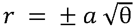
- In an embodiment, the spiral-shaped pattern is based on a square root spiral. The square root spiral is formed by right triangles placed edge to edge, i.e. a hypotenuse of one triangle is one leg of the triangle placed next to it and the other leg of the triangle always has a magnitude of 1. Thus, the nth triangle in the sequence is a right triangle with side lengths √n and 1, and with a hypotenuse of √n + 1.
- In an embodiment, the spiral-shaped pattern is based on a hyperbolic spiral. A hyperbolic spiral is an inverse spiral described with the equation r = a/θ; where θ ≠ 0. In this formula, r is the length of the radius from the center, a is a parameter and θ is the angular position of the radius. The hyperbolic spiral can be generated by a circle inversion of an Archimedean spiral.
- In an embodiment, the spiral-shaped pattern is based on Fibonacci numbers. A logarithmic spiral generated by Fibonacci numbers (Fibonacci spiral) has the growth factor of

- In an embodiment, the spiral-shaped pattern is a combination of two or more spirals. It is possible to use a combination of more than one preferably different spiral types on the distribution body, e.g. a spiral of type Fibonacci from the centre to a radius A, and a spiral of type Fermat from radius A to an outer most radius B, or any other combination from the spirals stated above.
- By choosing different spiral geometries, and even mixtures or geometrical sequences of different spiral types for different radial areas, it is possible to adjust the plating results to achieve high uniformities in the electrolytic deposition of the substrate. By placing the electrolyte and current distribution openings on a path of an imaginary spiral, on the distribution body surface as exemplified by the types of spirals, it is possible to target different surface areas of the substrate, which within themselves are required to be plated with very high uniformity.
- According to the present disclosure, also an electrochemical deposition system for a chemical and/or electrolytic surface treatment of a substrate is presented. The electrochemical deposition system comprises a distribution system as described above and a substrate rotation system. The substrate rotation system is configured to rotate a substrate relative to a distribution body of the distribution system.
- By rotating the substrate during application of the process fluid, even spread or distribution is ensured, therefore forming a homogenous, defect-pattern reduced or defect-pattern free coating on the substrate surface.
- A rotation of the substrate can mean a full rotation corresponding to a rotation of 360 degrees or a partial rotation of less than 360 degrees, for example corresponding to about 180 degrees. The substrate may rotate in both opposite directions, for example back and forth or in other words, clockwise and counterclockwise.
- A rotation speed of the rotation system can be set by a user depending on specific surface treatment needs such as for achieving a specific thickness of the accumulated coating in a defined time duration.
- In an example, the substrate may be placed in a substrate holder.
- In an example, the substrate may be releasable attached to the rotation system. This allows the substrate to be replaced by another substrate.
- According to the present disclosure, also a method for a chemical and/or electrolytic surface treatment of a substrate in a process fluid is presented. The method for a chemical and/or electrolytic surface treatment comprises the following steps, not necessarily in this order:
- providing a distribution system comprising a distribution body with a plurality of openings for the process fluid, wherein the openings are arranged in a spiral-shaped pattern on a surface of the distribution body,
- rotating the substrate relative to the distribution system, and
- chemically and/or electrolytically treating a surface of the substrate.
- The method may further comprise a step of selecting a source of process fluid before the step of chemically and/or electrolytically treating the surface.
- It shall be understood that the system, the device, and the method according to the independent claims have similar and/or identical preferred embodiments, in particular, as defined in the dependent claims. It shall be understood further that a preferred embodiment of the disclosure can also be any combination of the dependent claims with the respective independent claim.
- These and other aspects of the present disclosure will become apparent from and be elucidated with reference to the embodiments described hereinafter.
- Exemplary embodiments of the disclosure will be described in the following with reference to the accompanying drawing:
- Figure 1
- shows schematically and exemplarily an embodiment of a distribution body for a process fluid for chemical and/or electrolytic surface treatment of a rotatable substrate.
- Figure 2
- shows schematically and exemplarily an Archimedean spiral.
- Figure 3
- shows schematically and exemplarily a logarithmic spiral.
- Figure 4
- shows a graph depicting a distribution of a "drain hole ratio" as a function of a radius of a substrate.
-
Figure 1 shows schematically and exemplarily an embodiment of adistribution body 1 for a process fluid for chemical and/or electrolytic surface treatment of a rotatable substrate (not shown). Thedistribution body 1 is part of adistribution system 10 for a process fluid for chemical and/or electrolytic surface treatment of a rotatable substrate. Thedistribution body 1 may be arranged between an electrode (not shown) of thedistribution system 10 and the substrate. Thedistribution body 1 may be a high-speed plate (HSP). The substrate may rotate relative to thedistribution body 1. - The
distribution body 1 comprises a plurality ofopenings 2 for the process fluid. The process fluid is an electrolyte and may transport the current density. Theopenings 2 face the substrate and allow the process fluid to flow from the electrode to the substrate. Theopenings 2 are arranged in a spiral-shaped pattern on a surface of thedistribution body 1. Theopenings 2 direct the process fluid flow and/or a current density distribution to the substrate, and in case the substrate is rotating relative to thedistribution body 1, the spiral-shaped pattern enables that several areas of the substrate are exposed to similar process fluid flows and/or similar current density distributions, respectively. The electrolyte and the current density of the process fluid can be discharged from separate features and sections of thedistribution body 1. For this, thedistribution body 1 comprises at least one jet for discharging electrolyte and at least one distribution element for the current density distribution. - The
distribution system 10 is part of anelectrochemical deposition system 20 for a chemical and/or electrolytic surface treatment of a substrate. Theelectrochemical deposition system 20 comprises thedistribution system 10 and a substrate rotation system (not shown). The substrate rotation system is configured to rotate a substrate relative to adistribution body 1 of thedistribution system 10. By rotating the substrate during application of the process fluid, an even distribution of the process fluid is ensured, therefore forming a homogenous coating on the substrate surface. - The
openings 2 are arranged in a spiral-shaped pattern on thedistribution body 1, such as in an Archimedean spiral S1 pattern, as shown inFigure 2 , or a logarithmic spiral S2 pattern, as shown inFigure 3 . The spiral arrangement of theopenings 2 follows mathematical directives for a spiral where locations for theopenings 2 are determined corresponding to location points along lines described by a spiral moving continuously outward from a fixed starting point C. - With the spiral-shaped pattern of the
openings 2, each unit area of the substrate is exposed to the same amount of incoming electrolyte flow and current density averaged over the process time. A uniform electroplating without rotational artefacts is ensured when the substrate is rotating. - The spiral-shaped pattern is formed in that the
openings 2 are arranged along an imaginary curve, which winds around a starting point C on thedistribution body 1 at a continuously increasing distance from the starting point C. The starting point C of the spiral-shaped pattern is the geometric center C of thedistribution body 1 inFigure 1 . A distance betweenadjacent openings 2 along an imaginary spiral curve is constant from the starting point C of the spiral to more remote portions of thedistribution body 1. As shown inFigure 1 , theopenings 2 have an equal size throughout thedistribution body 1 and can have any cross-section, e.g. round, square or tri/multi-angular -
Figure 2 shows schematically and exemplarily an Archimedean spiral S1. The distance between neighboring arcs A is equal between each consecutive spiral loops or arcs A. The Archimedean spiral S1 is used to define the locations of theopenings 2 on asurface 1b of thedistribution body 1. -
Figure 3 shows schematically and exemplarily a logarithmic spiral S2, in which the distances between consecutive arcs A are increasing starting from the center to the outer portions. The logarithmic spiral S2 can also be used to define the locations of theopenings 2 on thesurface 1b of thedistribution body 1. -
Figure 4 shows a graph depicting a distribution of a "drain hole ratio" (DHR) as a function of a radius (r) of a rotating e.g. 300 mm wafer with an arrangement of electrolyte andcurrent distribution openings 2. The drain hole ratio describes a percentage of an open area (area of the openings 2) relative to a closed area (area without openings 2) along a specific radius of adistribution body 1 from a starting point C of a spiral to an outer edge of thedistribution body 1. The "X" symbols inFigure 4 depict the drain hole actual values of thedistribution body 1 and the "O" symbols depict averaged values over 10 neighbouring drain holes. - In principle it was found, that the more uniform the drain hole ratio distribution over the radius from the starting point to the outer edge, the higher the uniformity of the material deposition on the substrate, especially, when the substrate is in rotational movement relative to the
distribution body 1. As it can be seen fromFigure 4 , thedistribution body 1 allows an excellent drain hole uniformity over the radius, resulting in a significant improvement of the deposition uniformity distribution over the substrate. - It has to be noted that embodiments of the disclosure are described with reference to different subject matters. In particular, some embodiments are described with reference to method type claims whereas other embodiments are described with reference to the device type claims. However, a person skilled in the art will gather from the above and the following description that, unless otherwise notified, in addition to any combination of features belonging to one type of subject matter also any combination between features relating to different subject matters is considered to be disclosed with this application. However, all features can be combined providing synergetic effects that are more than the simple summation of the features.
- While the disclosure has been illustrated and described in detail in the drawings and foregoing description, such illustration and description are to be considered illustrative or exemplary and not restrictive. The disclosure is not limited to the disclosed embodiments. Other variations to the disclosed embodiments can be understood and effected by those skilled in the art in practicing a claimed disclosure, from a study of the drawings, the disclosure, and the dependent claims.
- In the claims, the word "comprising" does not exclude other elements or steps, and the indefinite article "a" or "an" does not exclude a plurality. A single processor or other unit may fulfil the functions of several items re-cited in the claims. The mere fact that certain measures are re-cited in mutually different dependent claims does not indicate that a combination of these measures cannot be used to advantage. Any reference signs in the claims should not be construed as limiting the scope. The invention is defined by the appended claims.
Claims (14)
- A distribution system (10) suitable for a process fluid for chemical and/or electrolytic surface treatment of a rotatable substrate,wherein the distribution system (10) comprises a distribution body (1),wherein the distribution body (1) comprises a plurality of openings (2),wherein some of the openings (2) are configured to provide the process fluid flow and other openings (2) are configured to provide a current density distribution,wherein the openings (2) for providing the process fluid flow are arranged in a spiral-shaped pattern on a surface (1b) of the distribution body (1), andwherein the openings (2) for providing the current density distribution are arranged on the surface (1b) of the distribution body (1) independently of the openings (2) for providing the process fluid flow.
- Distribution system (10) according to claim 1, in case the substrate is rotating relative to the distribution body (1), the spiral-shaped pattern enables several areas of the substrate to be exposed to similar process fluid flows and/or similar current density distributions, respectively.
- Distribution system (10) according to one of the preceding claims, wherein the spiral-shaped pattern is formed in that the openings (2) are arranged along an imaginary curve, which winds around a starting point (C) on the distribution body (1) at a continuously increasing distance from the starting point.
- Distribution system (10) according to claim 3, wherein the starting point (C) is a geometric centre (C) of the distribution body (1).
- Distribution system (10) according to claim 3, wherein the starting point (C) is outside a geometric centre (C) of the distribution body (1).
- Distribution system (10) according to one of the claims 1 to 5, wherein the spiral-shaped pattern is based on an Archimedean spiral (S1).
- Distribution system (10) according to one of the claims 1 to 5, wherein the spiral-shaped pattern is based on a logarithmic spiral (S2).
- Distribution system (10) according to one of the claims 1 to 5, wherein the spiral-shaped pattern is based on a parabolic spiral.
- Distribution system (10) according to one of the claims 1 to 5, wherein the spiral-shaped pattern is based on a square root spiral.
- Distribution system (10) according to one of the claims 1 to 5, wherein the spiral-shaped pattern is based on a hyperbolic spiral.
- Distribution system (10) according to one of the claims 1 to 5, wherein the spiral-shaped pattern is based on a Fibonacci spiral.
- Distribution system (10) according to one of the preceding claims, wherein the spiral-shaped pattern is a combination of two or more spirals.
- An electrochemical deposition system (20) for a chemical and/or electrolytic surface treatment of a substrate, comprising:- a distribution system (10) according to one of the preceding claims, and- a substrate rotation system,wherein the substrate rotation system is configured to rotate a substrate relative to a distribution body (1) of the distribution system (10).
- A method for a chemical and/or electrolytic surface treatment of a substrate in a process fluid, comprising:- providing a distribution system (10) comprising a distribution body (1) with a plurality of openings (2),- rotating the substrate relative to the distribution system (10), and- providing the process fluid flow via some of the openings (2) and providing a current density distribution via other openings (2),wherein the openings (2) for providing the process fluid flow are arranged in a spiral-shaped pattern on a surface (1b) of the distribution body (1), and
wherein the openings (2) for providing the current density distribution are arranged on the surface (1b) of the distribution body (1) independently of the openings (2) for providing the process fluid flow.
Priority Applications (10)
| Application Number | Priority Date | Filing Date | Title |
|---|---|---|---|
| PL20173988T PL3910095T3 (en) | 2020-05-11 | 2020-05-11 | Distribution system for a process fluid for chemical and/or electrolytic surface treatment of a rotatable substrate |
| EP20173988.5A EP3910095B1 (en) | 2020-05-11 | 2020-05-11 | Distribution system for a process fluid for chemical and/or electrolytic surface treatment of a rotatable substrate |
| PT201739885T PT3910095T (en) | 2020-05-11 | 2020-05-11 | DISTRIBUTION SYSTEM OF A PROCESS FLUID FOR CHEMICAL AND/OR ELECTROLYTIC SURFACE TREATMENT OF A ROTATING SUBSTRATE |
| US17/998,216 US20230193503A1 (en) | 2020-05-11 | 2021-05-03 | Distribution system for a process fluid for chemical and/or electrolytic surface treatment of a rotatable substrate |
| MYPI2022003756A MY208713A (en) | 2020-05-11 | 2021-05-03 | Distribution system for a process fluid for chemical and/or electrolytic surface treatment of a rotatable substrate |
| KR1020227027459A KR20220123464A (en) | 2020-05-11 | 2021-05-03 | Dispensing systems for process fluids for chemical and/or electrolytic surface treatment of rotatable substrates |
| PCT/EP2021/061575 WO2021228604A1 (en) | 2020-05-11 | 2021-05-03 | Distribution system for a process fluid for chemical and/or electrolytic surface treatment of a rotatable substrate |
| CN202180029794.2A CN115427614A (en) | 2020-05-11 | 2021-05-03 | Distribution system for process fluids for chemical and/or electrolytic surface treatment of rotatable substrates |
| JP2022549190A JP2023510024A (en) | 2020-05-11 | 2021-05-03 | Distribution system for process fluids for chemical and/or electrolytic surface treatment of rotatable substrates |
| TW110116872A TW202146713A (en) | 2020-05-11 | 2021-05-11 | Distribution system for a process fluid for chemical and/or electrolytic surface treatment of a rotatable substrate |
Applications Claiming Priority (1)
| Application Number | Priority Date | Filing Date | Title |
|---|---|---|---|
| EP20173988.5A EP3910095B1 (en) | 2020-05-11 | 2020-05-11 | Distribution system for a process fluid for chemical and/or electrolytic surface treatment of a rotatable substrate |
Publications (2)
| Publication Number | Publication Date |
|---|---|
| EP3910095A1 EP3910095A1 (en) | 2021-11-17 |
| EP3910095B1 true EP3910095B1 (en) | 2022-03-16 |
Family
ID=70681709
Family Applications (1)
| Application Number | Title | Priority Date | Filing Date |
|---|---|---|---|
| EP20173988.5A Active EP3910095B1 (en) | 2020-05-11 | 2020-05-11 | Distribution system for a process fluid for chemical and/or electrolytic surface treatment of a rotatable substrate |
Country Status (10)
| Country | Link |
|---|---|
| US (1) | US20230193503A1 (en) |
| EP (1) | EP3910095B1 (en) |
| JP (1) | JP2023510024A (en) |
| KR (1) | KR20220123464A (en) |
| CN (1) | CN115427614A (en) |
| MY (1) | MY208713A (en) |
| PL (1) | PL3910095T3 (en) |
| PT (1) | PT3910095T (en) |
| TW (1) | TW202146713A (en) |
| WO (1) | WO2021228604A1 (en) |
Families Citing this family (1)
| Publication number | Priority date | Publication date | Assignee | Title |
|---|---|---|---|---|
| CN114981485B (en) * | 2020-12-21 | 2023-03-28 | 株式会社荏原制作所 | Plating apparatus and method for stirring plating solution |
Family Cites Families (14)
| Publication number | Priority date | Publication date | Assignee | Title |
|---|---|---|---|---|
| US6103085A (en) * | 1998-12-04 | 2000-08-15 | Advanced Micro Devices, Inc. | Electroplating uniformity by diffuser design |
| US6368475B1 (en) * | 2000-03-21 | 2002-04-09 | Semitool, Inc. | Apparatus for electrochemically processing a microelectronic workpiece |
| US6254742B1 (en) * | 1999-07-12 | 2001-07-03 | Semitool, Inc. | Diffuser with spiral opening pattern for an electroplating reactor vessel |
| US6736952B2 (en) * | 2001-02-12 | 2004-05-18 | Speedfam-Ipec Corporation | Method and apparatus for electrochemical planarization of a workpiece |
| US6572755B2 (en) * | 2001-04-11 | 2003-06-03 | Speedfam-Ipec Corporation | Method and apparatus for electrochemically depositing a material onto a workpiece surface |
| ATE432145T1 (en) * | 2001-04-24 | 2009-06-15 | Applied Materials Inc | CONDUCTIVE POLISHING BODY FOR ELECTROCHEMICAL-MECHANICAL POLISHING |
| JP4310085B2 (en) * | 2002-07-31 | 2009-08-05 | 株式会社荏原製作所 | Electrolytic machining method and apparatus |
| US7645364B2 (en) * | 2004-06-30 | 2010-01-12 | Lam Research Corporation | Apparatus and method for plating semiconductor wafers |
| US8795480B2 (en) * | 2010-07-02 | 2014-08-05 | Novellus Systems, Inc. | Control of electrolyte hydrodynamics for efficient mass transfer during electroplating |
| DE102010033256A1 (en) * | 2010-07-29 | 2012-02-02 | Fraunhofer-Gesellschaft zur Förderung der angewandten Forschung e.V. | Method for generating targeted flow and current density patterns in chemical and electrolytic surface treatment |
| US8188575B2 (en) * | 2010-10-05 | 2012-05-29 | Skyworks Solutions, Inc. | Apparatus and method for uniform metal plating |
| US8968533B2 (en) * | 2012-05-10 | 2015-03-03 | Applied Materials, Inc | Electroplating processor with geometric electrolyte flow path |
| US10364505B2 (en) * | 2016-05-24 | 2019-07-30 | Lam Research Corporation | Dynamic modulation of cross flow manifold during elecroplating |
| US10781527B2 (en) * | 2017-09-18 | 2020-09-22 | Lam Research Corporation | Methods and apparatus for controlling delivery of cross flowing and impinging electrolyte during electroplating |
-
2020
- 2020-05-11 EP EP20173988.5A patent/EP3910095B1/en active Active
- 2020-05-11 PT PT201739885T patent/PT3910095T/en unknown
- 2020-05-11 PL PL20173988T patent/PL3910095T3/en unknown
-
2021
- 2021-05-03 WO PCT/EP2021/061575 patent/WO2021228604A1/en not_active Ceased
- 2021-05-03 CN CN202180029794.2A patent/CN115427614A/en active Pending
- 2021-05-03 US US17/998,216 patent/US20230193503A1/en not_active Abandoned
- 2021-05-03 KR KR1020227027459A patent/KR20220123464A/en not_active Ceased
- 2021-05-03 JP JP2022549190A patent/JP2023510024A/en active Pending
- 2021-05-03 MY MYPI2022003756A patent/MY208713A/en unknown
- 2021-05-11 TW TW110116872A patent/TW202146713A/en unknown
Also Published As
| Publication number | Publication date |
|---|---|
| KR20220123464A (en) | 2022-09-06 |
| CN115427614A (en) | 2022-12-02 |
| WO2021228604A1 (en) | 2021-11-18 |
| PT3910095T (en) | 2022-04-14 |
| PL3910095T3 (en) | 2022-05-23 |
| MY208713A (en) | 2025-05-27 |
| US20230193503A1 (en) | 2023-06-22 |
| EP3910095A1 (en) | 2021-11-17 |
| TW202146713A (en) | 2021-12-16 |
| JP2023510024A (en) | 2023-03-10 |
Similar Documents
| Publication | Publication Date | Title |
|---|---|---|
| US6103085A (en) | Electroplating uniformity by diffuser design | |
| CN101275267B (en) | Electroplating apparatus and electroplating method for improving thickness uniformity | |
| EP2935660B1 (en) | Device for vertical galvanic metal deposition on a substrate | |
| US5078852A (en) | Plating rack | |
| US6881309B2 (en) | Diffuser with spiral opening pattern for electroplating reactor vessel | |
| US20230193503A1 (en) | Distribution system for a process fluid for chemical and/or electrolytic surface treatment of a rotatable substrate | |
| WO2018017452A1 (en) | Electro-depositing metal layers of uniform thickness on semiconducting wafers | |
| US11105014B2 (en) | Distribution system for chemical and/or electrolytic surface treatment | |
| CN115768928A (en) | Electrodeposition of metals on substrates using ion-resistive ion-permeable elements or shields spatially tailored into die-level patterns | |
| HK40053204A (en) | Distribution system for a process fluid for chemical and/or electrolytic surface treatment of a rotatable substrate | |
| HK40053204B (en) | Distribution system for a process fluid for chemical and/or electrolytic surface treatment of a rotatable substrate | |
| TW201911408A (en) | Distribution system for chemical and/or electrolytic surface treatment | |
| US10604861B2 (en) | Device for vertical galvanic metal deposition on a substrate | |
| US20030155231A1 (en) | Field adjusting apparatus for an electroplating bath | |
| US20250116028A1 (en) | Electroplating chamber using jet array to enable high mass-transfer | |
| US12595581B2 (en) | Coplanarity improvement of high-rate CU pillar processes using high agitation to enable use of high acid, low CU chemistries | |
| CN112410850A (en) | Plating solution diffusion baffle of electroplating cavity | |
| US12630938B2 (en) | Shield body system for a process fluid for chemical and/or electrolytic surface treatment of a substrate | |
| EP3929332B1 (en) | Shield body system for a process fluid for chemical and/or electrolytic surface treatment of a substrate | |
| HK40058651A (en) | Shield body system for a process fluid for chemical and/or electrolytic surface treatment of a substrate |
Legal Events
| Date | Code | Title | Description |
|---|---|---|---|
| STAA | Information on the status of an ep patent application or granted ep patent |
Free format text: STATUS: EXAMINATION IS IN PROGRESS |
|
| PUAI | Public reference made under article 153(3) epc to a published international application that has entered the european phase |
Free format text: ORIGINAL CODE: 0009012 |
|
| 17P | Request for examination filed |
Effective date: 20210119 |
|
| AK | Designated contracting states |
Kind code of ref document: A1 Designated state(s): AL AT BE BG CH CY CZ DE DK EE ES FI FR GB GR HR HU IE IS IT LI LT LU LV MC MK MT NL NO PL PT RO RS SE SI SK SM TR |
|
| B565 | Issuance of search results under rule 164(2) epc |
Effective date: 20201026 |
|
| GRAP | Despatch of communication of intention to grant a patent |
Free format text: ORIGINAL CODE: EPIDOSNIGR1 |
|
| STAA | Information on the status of an ep patent application or granted ep patent |
Free format text: STATUS: GRANT OF PATENT IS INTENDED |
|
| RIC1 | Information provided on ipc code assigned before grant |
Ipc: C25D 21/10 20060101ALN20211112BHEP Ipc: H01L 21/67 20060101ALI20211112BHEP Ipc: C25D 17/00 20060101AFI20211112BHEP |
|
| INTG | Intention to grant announced |
Effective date: 20211222 |
|
| GRAS | Grant fee paid |
Free format text: ORIGINAL CODE: EPIDOSNIGR3 |
|
| REG | Reference to a national code |
Ref country code: HK Ref legal event code: DE Ref document number: 40053204 Country of ref document: HK |
|
| GRAA | (expected) grant |
Free format text: ORIGINAL CODE: 0009210 |
|
| STAA | Information on the status of an ep patent application or granted ep patent |
Free format text: STATUS: THE PATENT HAS BEEN GRANTED |
|
| AK | Designated contracting states |
Kind code of ref document: B1 Designated state(s): AL AT BE BG CH CY CZ DE DK EE ES FI FR GB GR HR HU IE IS IT LI LT LU LV MC MK MT NL NO PL PT RO RS SE SI SK SM TR |
|
| REG | Reference to a national code |
Ref country code: GB Ref legal event code: FG4D |
|
| REG | Reference to a national code |
Ref country code: CH Ref legal event code: EP |
|
| REG | Reference to a national code |
Ref country code: DE Ref legal event code: R096 Ref document number: 602020002211 Country of ref document: DE |
|
| REG | Reference to a national code |
Ref country code: IE Ref legal event code: FG4D |
|
| REG | Reference to a national code |
Ref country code: PT Ref legal event code: SC4A Ref document number: 3910095 Country of ref document: PT Date of ref document: 20220414 Kind code of ref document: T Free format text: AVAILABILITY OF NATIONAL TRANSLATION Effective date: 20220407 |
|
| REG | Reference to a national code |
Ref country code: AT Ref legal event code: REF Ref document number: 1475929 Country of ref document: AT Kind code of ref document: T Effective date: 20220415 |
|
| REG | Reference to a national code |
Ref country code: SE Ref legal event code: TRGR |
|
| REG | Reference to a national code |
Ref country code: NL Ref legal event code: FP |
|
| REG | Reference to a national code |
Ref country code: LT Ref legal event code: MG9D |
|
| PG25 | Lapsed in a contracting state [announced via postgrant information from national office to epo] |
Ref country code: RS Free format text: LAPSE BECAUSE OF FAILURE TO SUBMIT A TRANSLATION OF THE DESCRIPTION OR TO PAY THE FEE WITHIN THE PRESCRIBED TIME-LIMIT Effective date: 20220316 Ref country code: NO Free format text: LAPSE BECAUSE OF FAILURE TO SUBMIT A TRANSLATION OF THE DESCRIPTION OR TO PAY THE FEE WITHIN THE PRESCRIBED TIME-LIMIT Effective date: 20220616 Ref country code: LT Free format text: LAPSE BECAUSE OF FAILURE TO SUBMIT A TRANSLATION OF THE DESCRIPTION OR TO PAY THE FEE WITHIN THE PRESCRIBED TIME-LIMIT Effective date: 20220316 Ref country code: HR Free format text: LAPSE BECAUSE OF FAILURE TO SUBMIT A TRANSLATION OF THE DESCRIPTION OR TO PAY THE FEE WITHIN THE PRESCRIBED TIME-LIMIT Effective date: 20220316 Ref country code: BG Free format text: LAPSE BECAUSE OF FAILURE TO SUBMIT A TRANSLATION OF THE DESCRIPTION OR TO PAY THE FEE WITHIN THE PRESCRIBED TIME-LIMIT Effective date: 20220616 |
|
| PG25 | Lapsed in a contracting state [announced via postgrant information from national office to epo] |
Ref country code: LV Free format text: LAPSE BECAUSE OF FAILURE TO SUBMIT A TRANSLATION OF THE DESCRIPTION OR TO PAY THE FEE WITHIN THE PRESCRIBED TIME-LIMIT Effective date: 20220316 Ref country code: GR Free format text: LAPSE BECAUSE OF FAILURE TO SUBMIT A TRANSLATION OF THE DESCRIPTION OR TO PAY THE FEE WITHIN THE PRESCRIBED TIME-LIMIT Effective date: 20220617 Ref country code: FI Free format text: LAPSE BECAUSE OF FAILURE TO SUBMIT A TRANSLATION OF THE DESCRIPTION OR TO PAY THE FEE WITHIN THE PRESCRIBED TIME-LIMIT Effective date: 20220316 |
|
| PG25 | Lapsed in a contracting state [announced via postgrant information from national office to epo] |
Ref country code: SM Free format text: LAPSE BECAUSE OF FAILURE TO SUBMIT A TRANSLATION OF THE DESCRIPTION OR TO PAY THE FEE WITHIN THE PRESCRIBED TIME-LIMIT Effective date: 20220316 Ref country code: RO Free format text: LAPSE BECAUSE OF FAILURE TO SUBMIT A TRANSLATION OF THE DESCRIPTION OR TO PAY THE FEE WITHIN THE PRESCRIBED TIME-LIMIT Effective date: 20220316 Ref country code: ES Free format text: LAPSE BECAUSE OF FAILURE TO SUBMIT A TRANSLATION OF THE DESCRIPTION OR TO PAY THE FEE WITHIN THE PRESCRIBED TIME-LIMIT Effective date: 20220316 Ref country code: EE Free format text: LAPSE BECAUSE OF FAILURE TO SUBMIT A TRANSLATION OF THE DESCRIPTION OR TO PAY THE FEE WITHIN THE PRESCRIBED TIME-LIMIT Effective date: 20220316 |
|
| PG25 | Lapsed in a contracting state [announced via postgrant information from national office to epo] |
Ref country code: IS Free format text: LAPSE BECAUSE OF FAILURE TO SUBMIT A TRANSLATION OF THE DESCRIPTION OR TO PAY THE FEE WITHIN THE PRESCRIBED TIME-LIMIT Effective date: 20220716 Ref country code: AL Free format text: LAPSE BECAUSE OF FAILURE TO SUBMIT A TRANSLATION OF THE DESCRIPTION OR TO PAY THE FEE WITHIN THE PRESCRIBED TIME-LIMIT Effective date: 20220316 |
|
| REG | Reference to a national code |
Ref country code: DE Ref legal event code: R097 Ref document number: 602020002211 Country of ref document: DE |
|
| PLBE | No opposition filed within time limit |
Free format text: ORIGINAL CODE: 0009261 |
|
| STAA | Information on the status of an ep patent application or granted ep patent |
Free format text: STATUS: NO OPPOSITION FILED WITHIN TIME LIMIT |
|
| REG | Reference to a national code |
Ref country code: BE Ref legal event code: MM Effective date: 20220531 |
|
| PG25 | Lapsed in a contracting state [announced via postgrant information from national office to epo] |
Ref country code: MC Free format text: LAPSE BECAUSE OF FAILURE TO SUBMIT A TRANSLATION OF THE DESCRIPTION OR TO PAY THE FEE WITHIN THE PRESCRIBED TIME-LIMIT Effective date: 20220316 Ref country code: LU Free format text: LAPSE BECAUSE OF NON-PAYMENT OF DUE FEES Effective date: 20220511 Ref country code: DK Free format text: LAPSE BECAUSE OF FAILURE TO SUBMIT A TRANSLATION OF THE DESCRIPTION OR TO PAY THE FEE WITHIN THE PRESCRIBED TIME-LIMIT Effective date: 20220316 |
|
| 26N | No opposition filed |
Effective date: 20221219 |
|
| PG25 | Lapsed in a contracting state [announced via postgrant information from national office to epo] |
Ref country code: IE Free format text: LAPSE BECAUSE OF NON-PAYMENT OF DUE FEES Effective date: 20220511 |
|
| PG25 | Lapsed in a contracting state [announced via postgrant information from national office to epo] |
Ref country code: BE Free format text: LAPSE BECAUSE OF NON-PAYMENT OF DUE FEES Effective date: 20220531 |
|
| REG | Reference to a national code |
Ref country code: AT Ref legal event code: UEP Ref document number: 1475929 Country of ref document: AT Kind code of ref document: T Effective date: 20220316 |
|
| PGFP | Annual fee paid to national office [announced via postgrant information from national office to epo] |
Ref country code: PT Payment date: 20230419 Year of fee payment: 4 Ref country code: NL Payment date: 20230526 Year of fee payment: 4 Ref country code: IT Payment date: 20230531 Year of fee payment: 4 Ref country code: FR Payment date: 20230525 Year of fee payment: 4 Ref country code: DE Payment date: 20230530 Year of fee payment: 4 Ref country code: CZ Payment date: 20230426 Year of fee payment: 4 Ref country code: CH Payment date: 20230610 Year of fee payment: 4 |
|
| PGFP | Annual fee paid to national office [announced via postgrant information from national office to epo] |
Ref country code: SK Payment date: 20230418 Year of fee payment: 4 Ref country code: SE Payment date: 20230527 Year of fee payment: 4 Ref country code: PL Payment date: 20230419 Year of fee payment: 4 |
|
| P01 | Opt-out of the competence of the unified patent court (upc) registered |
Effective date: 20231021 |
|
| PG25 | Lapsed in a contracting state [announced via postgrant information from national office to epo] |
Ref country code: MK Free format text: LAPSE BECAUSE OF FAILURE TO SUBMIT A TRANSLATION OF THE DESCRIPTION OR TO PAY THE FEE WITHIN THE PRESCRIBED TIME-LIMIT Effective date: 20220316 Ref country code: CY Free format text: LAPSE BECAUSE OF FAILURE TO SUBMIT A TRANSLATION OF THE DESCRIPTION OR TO PAY THE FEE WITHIN THE PRESCRIBED TIME-LIMIT Effective date: 20220316 |
|
| PG25 | Lapsed in a contracting state [announced via postgrant information from national office to epo] |
Ref country code: HU Free format text: LAPSE BECAUSE OF FAILURE TO SUBMIT A TRANSLATION OF THE DESCRIPTION OR TO PAY THE FEE WITHIN THE PRESCRIBED TIME-LIMIT; INVALID AB INITIO Effective date: 20200511 |
|
| PG25 | Lapsed in a contracting state [announced via postgrant information from national office to epo] |
Ref country code: TR Free format text: LAPSE BECAUSE OF FAILURE TO SUBMIT A TRANSLATION OF THE DESCRIPTION OR TO PAY THE FEE WITHIN THE PRESCRIBED TIME-LIMIT Effective date: 20220316 |
|
| PG25 | Lapsed in a contracting state [announced via postgrant information from national office to epo] |
Ref country code: MT Free format text: LAPSE BECAUSE OF FAILURE TO SUBMIT A TRANSLATION OF THE DESCRIPTION OR TO PAY THE FEE WITHIN THE PRESCRIBED TIME-LIMIT Effective date: 20220316 |
|
| REG | Reference to a national code |
Ref country code: DE Ref legal event code: R119 Ref document number: 602020002211 Country of ref document: DE |
|
| PG25 | Lapsed in a contracting state [announced via postgrant information from national office to epo] |
Ref country code: PT Free format text: LAPSE BECAUSE OF NON-PAYMENT OF DUE FEES Effective date: 20241111 |
|
| REG | Reference to a national code |
Ref country code: CH Ref legal event code: PL |
|
| PG25 | Lapsed in a contracting state [announced via postgrant information from national office to epo] |
Ref country code: PT Free format text: LAPSE BECAUSE OF NON-PAYMENT OF DUE FEES Effective date: 20241111 |
|
| REG | Reference to a national code |
Ref country code: SE Ref legal event code: EUG |
|
| REG | Reference to a national code |
Ref country code: NL Ref legal event code: MM Effective date: 20240601 |
|
| REG | Reference to a national code |
Ref country code: SK Ref legal event code: MM4A Ref document number: E 39675 Country of ref document: SK Effective date: 20240511 |
|
| PG25 | Lapsed in a contracting state [announced via postgrant information from national office to epo] |
Ref country code: CZ Free format text: LAPSE BECAUSE OF NON-PAYMENT OF DUE FEES Effective date: 20240511 |
|
| PG25 | Lapsed in a contracting state [announced via postgrant information from national office to epo] |
Ref country code: SK Free format text: LAPSE BECAUSE OF NON-PAYMENT OF DUE FEES Effective date: 20240511 |
|
| GBPC | Gb: european patent ceased through non-payment of renewal fee |
Effective date: 20240511 |
|
| PG25 | Lapsed in a contracting state [announced via postgrant information from national office to epo] |
Ref country code: SK Free format text: LAPSE BECAUSE OF NON-PAYMENT OF DUE FEES Effective date: 20240511 Ref country code: CZ Free format text: LAPSE BECAUSE OF NON-PAYMENT OF DUE FEES Effective date: 20240511 Ref country code: CH Free format text: LAPSE BECAUSE OF NON-PAYMENT OF DUE FEES Effective date: 20240531 |
|
| PG25 | Lapsed in a contracting state [announced via postgrant information from national office to epo] |
Ref country code: NL Free format text: LAPSE BECAUSE OF NON-PAYMENT OF DUE FEES Effective date: 20240601 |
|
| PG25 | Lapsed in a contracting state [announced via postgrant information from national office to epo] |
Ref country code: DE Free format text: LAPSE BECAUSE OF NON-PAYMENT OF DUE FEES Effective date: 20241203 |
|
| PG25 | Lapsed in a contracting state [announced via postgrant information from national office to epo] |
Ref country code: FR Free format text: LAPSE BECAUSE OF NON-PAYMENT OF DUE FEES Effective date: 20240531 |
|
| PG25 | Lapsed in a contracting state [announced via postgrant information from national office to epo] |
Ref country code: IT Free format text: LAPSE BECAUSE OF NON-PAYMENT OF DUE FEES Effective date: 20240511 Ref country code: GB Free format text: LAPSE BECAUSE OF NON-PAYMENT OF DUE FEES Effective date: 20240511 |
|
| PGFP | Annual fee paid to national office [announced via postgrant information from national office to epo] |
Ref country code: AT Payment date: 20250721 Year of fee payment: 5 |
|
| PG25 | Lapsed in a contracting state [announced via postgrant information from national office to epo] |
Ref country code: SE Free format text: LAPSE BECAUSE OF NON-PAYMENT OF DUE FEES Effective date: 20240512 |
|
| PG25 | Lapsed in a contracting state [announced via postgrant information from national office to epo] |
Ref country code: PL Free format text: LAPSE BECAUSE OF NON-PAYMENT OF DUE FEES Effective date: 20240511 |
|
| PG25 | Lapsed in a contracting state [announced via postgrant information from national office to epo] |
Ref country code: SI Free format text: LAPSE BECAUSE OF FAILURE TO SUBMIT A TRANSLATION OF THE DESCRIPTION OR TO PAY THE FEE WITHIN THE PRESCRIBED TIME-LIMIT Effective date: 20220316 |