EP3909854A1 - Translucent illuminated evacuation slide - Google Patents
Translucent illuminated evacuation slide Download PDFInfo
- Publication number
- EP3909854A1 EP3909854A1 EP21183482.5A EP21183482A EP3909854A1 EP 3909854 A1 EP3909854 A1 EP 3909854A1 EP 21183482 A EP21183482 A EP 21183482A EP 3909854 A1 EP3909854 A1 EP 3909854A1
- Authority
- EP
- European Patent Office
- Prior art keywords
- tubular member
- slide
- light source
- light
- chamber
- Prior art date
- Legal status (The legal status is an assumption and is not a legal conclusion. Google has not performed a legal analysis and makes no representation as to the accuracy of the status listed.)
- Granted
Links
Images

Classifications
-
- B—PERFORMING OPERATIONS; TRANSPORTING
- B64—AIRCRAFT; AVIATION; COSMONAUTICS
- B64D—EQUIPMENT FOR FITTING IN OR TO AIRCRAFT; FLIGHT SUITS; PARACHUTES; ARRANGEMENT OR MOUNTING OF POWER PLANTS OR PROPULSION TRANSMISSIONS IN AIRCRAFT
- B64D25/00—Emergency apparatus or devices, not otherwise provided for
- B64D25/08—Ejecting or escaping means
- B64D25/14—Inflatable escape chutes
-
- B—PERFORMING OPERATIONS; TRANSPORTING
- B64—AIRCRAFT; AVIATION; COSMONAUTICS
- B64D—EQUIPMENT FOR FITTING IN OR TO AIRCRAFT; FLIGHT SUITS; PARACHUTES; ARRANGEMENT OR MOUNTING OF POWER PLANTS OR PROPULSION TRANSMISSIONS IN AIRCRAFT
- B64D47/00—Equipment not otherwise provided for
- B64D47/02—Arrangements or adaptations of signal or lighting devices
Definitions
- the present disclosure relates to inflatable emergency slides and, in particular, to an illuminated evacuation slide having translucent skin.
- evacuation slides that deploy beneath exit doors during evacuation.
- the evacuation slides may be used in case of emergency by passengers exiting the aircraft.
- slide visibility may be limited. Limited visibility may cause hesitation in passengers and slow their evacuation.
- An inflatable slide may comprise a slide surface with a tubular member coupled to the slide surface.
- the tubular member may comprise a translucent material defining a chamber internal to the tubular member.
- a light source may be directed into the chamber and configured to illuminate the tubular member from within the chamber.
- the tubular member may comprise a synthetic textile.
- the synthetic textile may be coated in urethane.
- the light source may be disposed inside of the chamber.
- the light source may comprise a light emitting diode and may be disposed external to the chamber.
- the synthetic textile or the urethane may include a color to add the color to light emitted from the light source.
- An evacuation system may comprise a door sill, a girt coupled to the door sill, and a first tubular member defining a first chamber.
- the first tubular member may be coupled to the girt and comprise a translucent material.
- a slide surface may also be coupled to the first tubular member.
- a first light source may be coupled to the first tubular member and configured illuminate the first tubular member from within the first chamber.
- the evacuation system may also include a second tubular member defining a second chamber and coupled to the slide surface.
- a second light source may be coupled to the second tubular member and configured to illuminate the second tubular member from within.
- the first light source may be staggered relative to the second light source.
- the first tubular member may comprise a synthetic textile.
- the synthetic textile may be coated in urethane.
- the first light source may be disposed inside of the first chamber.
- the first light source may comprise a light emitting diode.
- the first light source may be disposed external to the first chamber.
- the synthetic textile or the urethane may include a color to add the color to light emitted from the first light source.
- An evacuation slide may comprise a first tubular member defining a first chamber.
- the first tubular member may include a translucent material.
- a slide surface may be coupled to the first tubular member.
- a first light source may be coupled to the first tubular member and configured illuminate the first tubular member from within the first chamber.
- a second tubular member may define a second chamber and be coupled to the slide surface.
- a second light source may also be coupled to the second tubular member with the second light source configured to illuminate the second tubular member from within.
- the first light source may be staggered relative to the second light source.
- the first tubular member may comprise a synthetic textile coated in urethane, neoprene, or polyurethane.
- the first light source may comprise a light emitting diode and may be disposed inside the first chamber.
- any reference to singular includes plural embodiments, and any reference to more than one component or step may include a singular embodiment or step.
- any reference to attached, fixed, connected or the like may include permanent, removable, temporary, partial, full and/or any other possible attachment option.
- any reference to without contact (or similar phrases) may also include reduced contact or minimal contact.
- Cross hatching lines may be used throughout the figures to denote different parts but not necessarily to denote the same or different materials.
- Slides according to the present disclosure provide improved lighting for night-time use by shining light sources on the skin of the slide.
- the skin may be translucent or transparent and may distribute light along the skin.
- night time visibility of slide surfaces may be improved by illuminating the surfaces that make up the slide.
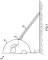
- Evacuation system 100 may comprise a fuselage 102 with a door sill 104.
- Inflatable slide 106 may be coupled to door sill 104 by girt 108.
- Inflatable slide 106 may comprise one or more inflatable chambers made from a translucent, transparent, and/or semi-transparent material with lights disposed at various locations about the inflatable chambers.
- Slide 200 may comprise chambers 206 that are inflatable and defined by tubular members 202.
- Tubular members 202 may be cylindrical, tubular, rectangular, elliptical, or other suitable shape to provide support for slide 200 when inflated.
- Chamber 206 may inflate to deploy slide 200 in case of an evacuation event.
- Slide 200 may further comprise a slide surface 204 coupled to tubular members 202 defining chambers 206.
- slide 200 may be made from translucent, transparent, and/or semi-transparent materials.
- Translucent materials may include materials having a light transmission rate greater than 20%.
- Transparent materials may include materials that have a light transmission rate greater than 90%.
- Translucent, transparent, and/or semi-transparent materials may include sheer textiles.
- slide 200 may be made from synthetic fibers woven to form a synthetic textile such as nylon, polyester, acrylic, rayon, acetate, latex, or other suitable materials. The textile may be coated to render the material sufficiently air tight to allow for inflation of chamber 206 defined by walls of tubular member 202 made from the textile.
- the textile may be dipped in or sprayed with urethane, polyurethane, neoprene, or other plastic in liquid form that allows the textile to retain flexibility while making the coated textile impermeable or substantially impermeable to gas.
- the coating may be applied in a thin layer to retain the light transmission properties of the material.
- the textile and/or the coating may be colored with a dye or tint to give light emitted from slide 200 a colored hue.
- the coating may be green to cause the slide to emit a green light in response to light shone through a surface of the slide.
- the textile may be sewn into a desired shape to form tubular member 202 and slide surface 204 of slide 200.
- light sources 208 may be disposed on internal surfaces of tubular members 202.
- Light sources 208 may be light-emitting diode (LED), phosphorescent lights, incandescent lights, florescent lights, light strips, or any other suitable light source.
- a light source 208 may include multiple LED light engines disposed at intervals along inner surfaces of slide 200 to illuminate slide 200 in a back-lighted, glowing manner. LED lighting may reduce the weight of slide 200 relative to other light sources. LED lighting may also conserve space and provide flexibility relative to other light sources such that light source 208 using LED lighting may be folded and stowed with slide 200 when slide 200 is packed for installation.
- the brightness and number of light sources 208 may be selected based on power and the total light output criteria.
- light source 208 may be directed inward with light 210 emitted from light source 208 directed into chamber 206.
- Light 210 emitted from light source 208 may contact an inner surface of tubular member 202 and be partially reflected within chamber 206.
- Light 210 may be distributed about tubular member 202 in response to being partially reflected by the inner surface of tubular member 202 so that the outer surface of tubular member 202 emits light 212.
- Light 212 may cause slide 200 to have glowing surfaces where light 212 is emitted.
- the coated textile material of tubular members 202 may diffract and diffuse light 210 from light source 208 within chamber 206.
- light sources 208 may be distributed along tubular member 202 at intervals.
- light sources 208 may be spaced 6 feet (1.8 m) to 10 feet (3.0 m) apart.
- Light sources may also be spaced 4 feet (1.2 m) to 12 feet (3.7 m) apart.
- the spacing of light sources may also be staggered within adjacent tubular members 202 so that tubular members 202 illuminate slide surface 204.
- Staggered light sources may be located at different points along the lengths of two tubular members 202.
- Light sources may also be directed at slide surface 204 to illuminate slide surface 204 in a glowing, back-lighted manner as described with respect to tubular members 202. Illuminated surfaces of slide 200 may improve visibility for night-time use.
- light sources 208 may be powered by one or more power sources such as a battery, solar cell, or generator. Light sources 208 may be powered by wires electrically coupled to a power source. Light sources 208 may be wired in series or in parallel to power multiple light sources with a single power source. Light sources 208 may also be self-contained and powered by an individual battery for each light source 208.
- power sources such as a battery, solar cell, or generator.
- Light sources 208 may be powered by wires electrically coupled to a power source.
- Light sources 208 may be wired in series or in parallel to power multiple light sources with a single power source. Light sources 208 may also be self-contained and powered by an individual battery for each light source 208.
- a slide 300 is shown lighted by a light source 308 disposed external to chamber 306, in accordance with various embodiments.
- Light sources 308 may also be installed in varying orientations on the tube. Installation of light sources 308 on an inside rail may also supply additional lighting on slide surface 304.
- Slide 300 may be similar to slide 200 of FIG. 2 , as described above, but with light sources 308 mounted externally.
- Tubular member 302 may define a chamber 306 that is inflatable and provides support for slide surface 304 when inflated.
- Light source 308 is disposed external to chamber 306, on an outer surface of tubular member 302. Light source 308 may be directed into chamber 306 with light emitted from light source 308 entering chamber 306.
- Light source 308 may shine through the synthetic textile of tubular member 302.
- a transparent window may be formed in tubular member 302 to enhance light transmission of light 310 into chamber 306.
- Light 310 within chamber 306 may be distributed about tubular member 302 by diffraction and reflection.
- Light 312 may be emitted from the outer surface of tubular member 302.
- light source 308 located externally to chamber 306 may be used in conjunction with internally located light sources 208 of FIG. 2A to illuminate a slide 300.
- slide 300 may comprise internally located light sources and externally located light sources.
- Light sources 308 mounted externally may be LED, phosphorescent lights, incandescent lights, florescent lights, light strips, or any other suitable light source.
- a light source 308 may include multiple LED light engines disposed at intervals along surfaces of slide 300 to illuminate slide 300 in a back-lighted, glowing manner. Externally mounted LED lighting may conserve space and provide flexibility relative to other light sources such that light source 308 using LED lighting may be folded and stowed with slide 200 when slide is packed for installation.
- light sources 308 may be distributed along tubular member 302 at intervals. For example, light sources 308 may be spaced 6 feet (1.8 m) to 10 feet (3.0 m) apart. Light sources 308 may also be spaced 4 feet (1.2 m) to 12 feet (3.7 m) apart. The spacing of light sources may also be staggered within adjacent tubular members 302 so that tubular members 302 illuminate slide surface 304. Light sources 308 may also be directed at slide surface 304 to illuminate slide surface 304 in a glowing, back-lighted manner as described with respect to tubular members 302. Illuminated surfaces of slide 300 may improve visibility for night-time use.
- light sources 308 may be powered by one or more power sources such as a battery, solar cell, or generator. Light sources 308 may be powered by wires electrically coupled to a power source. Light sources 308 may be wired in series or in parallel to power multiple light sources with a single power source. Light sources 308 may also be self-contained and powered by an individual battery for each light source 308, or light sources 308 may be aircraft-powered.
- power sources such as a battery, solar cell, or generator.
- Light sources 308 may be powered by wires electrically coupled to a power source. Light sources 308 may be wired in series or in parallel to power multiple light sources with a single power source. Light sources 308 may also be self-contained and powered by an individual battery for each light source 308, or light sources 308 may be aircraft-powered.
- references to "various embodiments”, “one embodiment”, “an embodiment”, “an example embodiment”, etc. indicate that the embodiment described may include a particular feature, structure, or characteristic, but every embodiment may not necessarily include the particular feature, structure, or characteristic. Moreover, such phrases are not necessarily referring to the same embodiment. Further, when a particular feature, structure, or characteristic is described in connection with an embodiment, it is submitted that it is within the knowledge of one skilled in the art to affect such feature, structure, or characteristic in connection with other embodiments whether or not explicitly described. After reading the description, it will be apparent to one skilled in the relevant art(s) how to implement the disclosure in alternative embodiments.
Landscapes
- Engineering & Computer Science (AREA)
- Aviation & Aerospace Engineering (AREA)
- Business, Economics & Management (AREA)
- Emergency Management (AREA)
- Non-Portable Lighting Devices Or Systems Thereof (AREA)
- Power-Operated Mechanisms For Wings (AREA)
- Professional, Industrial, Or Sporting Protective Garments (AREA)
Abstract
Description
- The present disclosure relates to inflatable emergency slides and, in particular, to an illuminated evacuation slide having translucent skin.
- Commercial aircraft typically employ evacuation slides that deploy beneath exit doors during evacuation. The evacuation slides may be used in case of emergency by passengers exiting the aircraft. During night evacuations, slide visibility may be limited. Limited visibility may cause hesitation in passengers and slow their evacuation.
- An inflatable slide may comprise a slide surface with a tubular member coupled to the slide surface. The tubular member may comprise a translucent material defining a chamber internal to the tubular member. A light source may be directed into the chamber and configured to illuminate the tubular member from within the chamber.
- In various embodiments, the tubular member may comprise a synthetic textile. The synthetic textile may be coated in urethane. The light source may be disposed inside of the chamber. The light source may comprise a light emitting diode and may be disposed external to the chamber. The synthetic textile or the urethane may include a color to add the color to light emitted from the light source.
- An evacuation system may comprise a door sill, a girt coupled to the door sill, and a first tubular member defining a first chamber. The first tubular member may be coupled to the girt and comprise a translucent material. A slide surface may also be coupled to the first tubular member. A first light source may be coupled to the first tubular member and configured illuminate the first tubular member from within the first chamber.
- In various embodiments, the evacuation system may also include a second tubular member defining a second chamber and coupled to the slide surface. A second light source may be coupled to the second tubular member and configured to illuminate the second tubular member from within. The first light source may be staggered relative to the second light source. The first tubular member may comprise a synthetic textile. The synthetic textile may be coated in urethane. The first light source may be disposed inside of the first chamber. The first light source may comprise a light emitting diode. The first light source may be disposed external to the first chamber. The synthetic textile or the urethane may include a color to add the color to light emitted from the first light source.
- An evacuation slide may comprise a first tubular member defining a first chamber. The first tubular member may include a translucent material. A slide surface may be coupled to the first tubular member. A first light source may be coupled to the first tubular member and configured illuminate the first tubular member from within the first chamber. A second tubular member may define a second chamber and be coupled to the slide surface. A second light source may also be coupled to the second tubular member with the second light source configured to illuminate the second tubular member from within.
- In various embodiments, the first light source may be staggered relative to the second light source. The first tubular member may comprise a synthetic textile coated in urethane, neoprene, or polyurethane. The first light source may comprise a light emitting diode and may be disposed inside the first chamber.
- The foregoing features and elements may be combined in various combinations without exclusivity, unless expressly indicated otherwise. These features and elements as well as the operation thereof will become more apparent in light of the following description and the accompanying drawings. It should be understood, however, the following description and drawings are intended to be exemplary in nature and non-limiting.
- The subject matter of the present disclosure is particularly pointed out and distinctly claimed in the concluding portion of the specification. A more complete understanding of the present disclosure, however, may best be obtained by referring to the detailed description and claims when considered in connection with the figures, wherein like numerals denote like elements.
-
FIG. 1 illustrates an exemplary emergency evacuation system having an inflatable slide, in accordance with various embodiments; -
FIG. 2A illustrates a cross-sectional view of an inflatable slide lighted by an internal light source, in accordance with various embodiments; -
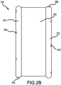
FIG. 2B illustrates a top view of an inflatable slide with internal light sources disposed along the inside of inflatable tubing; -
FIG. 3A illustrates a cross-sectional view of an inflatable slide lighted by an external light source, in accordance with various embodiments; and -
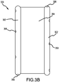
FIG. 3B illustrates a top view of an inflatable slide with external light sources disposed along the outside of inflatable tubing, in accordance with various embodiments. - The detailed description of exemplary embodiments herein makes reference to the accompanying drawings, which show exemplary embodiments by way of illustration. While these exemplary embodiments are described in sufficient detail to enable those skilled in the art to practice the exemplary embodiments of the disclosure, it should be understood that other embodiments may be realized and that logical changes and adaptations in design and construction may be made in accordance with this disclosure and the teachings herein. Thus, the detailed description herein is presented for purposes of illustration only and not limitation. The steps recited in any of the method or process descriptions may be executed in any order and are not necessarily limited to the order presented.
- Furthermore, any reference to singular includes plural embodiments, and any reference to more than one component or step may include a singular embodiment or step. Also, any reference to attached, fixed, connected or the like may include permanent, removable, temporary, partial, full and/or any other possible attachment option. Additionally, any reference to without contact (or similar phrases) may also include reduced contact or minimal contact. Cross hatching lines may be used throughout the figures to denote different parts but not necessarily to denote the same or different materials.
- Slides according to the present disclosure provide improved lighting for night-time use by shining light sources on the skin of the slide. The skin may be translucent or transparent and may distribute light along the skin. In that regard, night time visibility of slide surfaces may be improved by illuminating the surfaces that make up the slide.
- With reference to
FIG. 1 , anexemplary evacuation system 100 is shown, in accordance with various embodiments.Evacuation system 100 may comprise afuselage 102 with a door sill 104.Inflatable slide 106 may be coupled to door sill 104 bygirt 108.Inflatable slide 106 may comprise one or more inflatable chambers made from a translucent, transparent, and/or semi-transparent material with lights disposed at various locations about the inflatable chambers. - With reference to
FIG. 2A , aslide 200 is shown havinglight sources 208 internally located, in accordance with various embodiments.Slide 200 may comprisechambers 206 that are inflatable and defined bytubular members 202.Tubular members 202 may be cylindrical, tubular, rectangular, elliptical, or other suitable shape to provide support forslide 200 when inflated.Chamber 206 may inflate to deployslide 200 in case of an evacuation event.Slide 200 may further comprise aslide surface 204 coupled totubular members 202 definingchambers 206. - In various embodiments, slide 200 may be made from translucent, transparent, and/or semi-transparent materials. Translucent materials may include materials having a light transmission rate greater than 20%. Transparent materials may include materials that have a light transmission rate greater than 90%. Translucent, transparent, and/or semi-transparent materials may include sheer textiles. For example, slide 200 may be made from synthetic fibers woven to form a synthetic textile such as nylon, polyester, acrylic, rayon, acetate, latex, or other suitable materials. The textile may be coated to render the material sufficiently air tight to allow for inflation of
chamber 206 defined by walls oftubular member 202 made from the textile. For example, the textile may be dipped in or sprayed with urethane, polyurethane, neoprene, or other plastic in liquid form that allows the textile to retain flexibility while making the coated textile impermeable or substantially impermeable to gas. The coating may be applied in a thin layer to retain the light transmission properties of the material. The textile and/or the coating may be colored with a dye or tint to give light emitted from slide 200 a colored hue. For example, the coating may be green to cause the slide to emit a green light in response to light shone through a surface of the slide. The textile may be sewn into a desired shape to formtubular member 202 andslide surface 204 ofslide 200. - With reference to
FIGs. 2A and2B ,light sources 208 may be disposed on internal surfaces oftubular members 202.Light sources 208 may be light-emitting diode (LED), phosphorescent lights, incandescent lights, florescent lights, light strips, or any other suitable light source. For example, alight source 208 may include multiple LED light engines disposed at intervals along inner surfaces ofslide 200 to illuminateslide 200 in a back-lighted, glowing manner. LED lighting may reduce the weight ofslide 200 relative to other light sources. LED lighting may also conserve space and provide flexibility relative to other light sources such thatlight source 208 using LED lighting may be folded and stowed withslide 200 whenslide 200 is packed for installation. The brightness and number oflight sources 208 may be selected based on power and the total light output criteria. - In various embodiments,
light source 208 may be directed inward with light 210 emitted fromlight source 208 directed intochamber 206.Light 210 emitted fromlight source 208 may contact an inner surface oftubular member 202 and be partially reflected withinchamber 206.Light 210 may be distributed abouttubular member 202 in response to being partially reflected by the inner surface oftubular member 202 so that the outer surface oftubular member 202 emits light 212.Light 212 may causeslide 200 to have glowing surfaces where light 212 is emitted. In that regard, the coated textile material oftubular members 202 may diffract and diffuse light 210 fromlight source 208 withinchamber 206. - In various embodiments,
light sources 208 may be distributed alongtubular member 202 at intervals. For example,light sources 208 may be spaced 6 feet (1.8 m) to 10 feet (3.0 m) apart. Light sources may also be spaced 4 feet (1.2 m) to 12 feet (3.7 m) apart. The spacing of light sources may also be staggered within adjacenttubular members 202 so thattubular members 202 illuminateslide surface 204. Staggered light sources may be located at different points along the lengths of twotubular members 202. Light sources may also be directed atslide surface 204 to illuminateslide surface 204 in a glowing, back-lighted manner as described with respect totubular members 202. Illuminated surfaces ofslide 200 may improve visibility for night-time use. - In various embodiments,
light sources 208 may be powered by one or more power sources such as a battery, solar cell, or generator.Light sources 208 may be powered by wires electrically coupled to a power source.Light sources 208 may be wired in series or in parallel to power multiple light sources with a single power source.Light sources 208 may also be self-contained and powered by an individual battery for eachlight source 208. - With reference to
FIGs. 3A and3B , aslide 300 is shown lighted by alight source 308 disposed external tochamber 306, in accordance with various embodiments.Light sources 308 may also be installed in varying orientations on the tube. Installation oflight sources 308 on an inside rail may also supply additional lighting onslide surface 304.Slide 300 may be similar to slide 200 ofFIG. 2 , as described above, but withlight sources 308 mounted externally.Tubular member 302 may define achamber 306 that is inflatable and provides support forslide surface 304 when inflated.Light source 308 is disposed external tochamber 306, on an outer surface oftubular member 302.Light source 308 may be directed intochamber 306 with light emitted fromlight source 308 enteringchamber 306.Light source 308 may shine through the synthetic textile oftubular member 302. A transparent window may be formed intubular member 302 to enhance light transmission of light 310 intochamber 306.Light 310 withinchamber 306 may be distributed abouttubular member 302 by diffraction and reflection.Light 312 may be emitted from the outer surface oftubular member 302. - In various embodiments,
light source 308 located externally tochamber 306 may be used in conjunction with internally locatedlight sources 208 ofFIG. 2A to illuminate aslide 300. In that regard, slide 300 may comprise internally located light sources and externally located light sources.Light sources 308 mounted externally may be LED, phosphorescent lights, incandescent lights, florescent lights, light strips, or any other suitable light source. For example, alight source 308 may include multiple LED light engines disposed at intervals along surfaces ofslide 300 to illuminateslide 300 in a back-lighted, glowing manner. Externally mounted LED lighting may conserve space and provide flexibility relative to other light sources such thatlight source 308 using LED lighting may be folded and stowed withslide 200 when slide is packed for installation. - In various embodiments,
light sources 308 may be distributed alongtubular member 302 at intervals. For example,light sources 308 may be spaced 6 feet (1.8 m) to 10 feet (3.0 m) apart.Light sources 308 may also be spaced 4 feet (1.2 m) to 12 feet (3.7 m) apart. The spacing of light sources may also be staggered within adjacenttubular members 302 so thattubular members 302 illuminateslide surface 304.Light sources 308 may also be directed atslide surface 304 to illuminateslide surface 304 in a glowing, back-lighted manner as described with respect totubular members 302. Illuminated surfaces ofslide 300 may improve visibility for night-time use. - In various embodiments,
light sources 308 may be powered by one or more power sources such as a battery, solar cell, or generator.Light sources 308 may be powered by wires electrically coupled to a power source.Light sources 308 may be wired in series or in parallel to power multiple light sources with a single power source.Light sources 308 may also be self-contained and powered by an individual battery for eachlight source 308, orlight sources 308 may be aircraft-powered. - Benefits and other advantages have been described herein with regard to specific embodiments. Furthermore, the connecting lines shown in the various figures contained herein are intended to represent exemplary functional relationships and/or physical couplings between the various elements. It should be noted that many alternative or additional functional relationships or physical connections may be present in a practical system. However, the benefits, advantages, and any elements that may cause any benefit or advantage to occur or become more pronounced are not to be construed as critical, required, or essential features or elements of the disclosure. The scope of the disclosure is accordingly to be limited by nothing other than the appended claims, in which reference to an element in the singular is not intended to mean "one and only one" unless explicitly so stated, but rather "one or more." Moreover, where a phrase similar to "at least one of A, B, or C" is used in the claims, it is intended that the phrase be interpreted to mean that A alone may be present in an embodiment, B alone may be present in an embodiment, C alone may be present in an embodiment, or that any combination of the elements A, B and C may be present in a single embodiment; for example, A and B, A and C, B and C, or A and B and C.
- Systems, methods and apparatus are provided herein. In the detailed description herein, references to "various embodiments", "one embodiment", "an embodiment", "an example embodiment", etc., indicate that the embodiment described may include a particular feature, structure, or characteristic, but every embodiment may not necessarily include the particular feature, structure, or characteristic. Moreover, such phrases are not necessarily referring to the same embodiment. Further, when a particular feature, structure, or characteristic is described in connection with an embodiment, it is submitted that it is within the knowledge of one skilled in the art to affect such feature, structure, or characteristic in connection with other embodiments whether or not explicitly described. After reading the description, it will be apparent to one skilled in the relevant art(s) how to implement the disclosure in alternative embodiments.
Claims (5)
- An evacuation slide, comprising:a first tubular member (202, 302) defining a first chamber (206, 306), wherein the first tubular member (202, 302) comprises a translucent material;a slide surface coupled to the first tubular member (202, 302);a first light source (208, 308) coupled to the first tubular member (202, 302) and configured illuminate the first tubular member (202, 302) from within the first chamber (206, 306);a second tubular member (202, 302) defining a second chamber (206, 306) and coupled to the slide surface; anda second light source (208, 308) coupled to the second tubular member (202, 302) and configured to illuminate the second tubular member (202, 302) from within.
- The evacuation slide of claim 1, wherein the first light source (208, 308) is staggered relative to the second light source (208, 308).
- The evacuation slide of claim 1 or 2, wherein the first tubular member (202, 302) comprises a synthetic textile is coated in urethane.
- The evacuation slide of claim 1, 2 or 3, wherein the first light source (208, 308) comprises a light emitting diode.
- The evacuation slide of claim 1, 2, 3 or 4, wherein the first light source (208, 308) is disposed inside the first chamber (206, 306).
Applications Claiming Priority (3)
| Application Number | Priority Date | Filing Date | Title |
|---|---|---|---|
| US14/829,369 US10160551B2 (en) | 2015-08-18 | 2015-08-18 | Translucent illuminated evacuation slide |
| EP16184624.1A EP3184432B1 (en) | 2015-08-18 | 2016-08-17 | Translucent illuminated evacuation slide |
| EP19190549.6A EP3584166B1 (en) | 2015-08-18 | 2016-08-17 | Translucent illuminated evacuation slide |
Related Parent Applications (3)
| Application Number | Title | Priority Date | Filing Date |
|---|---|---|---|
| EP16184624.1A Division EP3184432B1 (en) | 2015-08-18 | 2016-08-17 | Translucent illuminated evacuation slide |
| EP19190549.6A Division EP3584166B1 (en) | 2015-08-18 | 2016-08-17 | Translucent illuminated evacuation slide |
| EP19190549.6A Division-Into EP3584166B1 (en) | 2015-08-18 | 2016-08-17 | Translucent illuminated evacuation slide |
Publications (2)
| Publication Number | Publication Date |
|---|---|
| EP3909854A1 true EP3909854A1 (en) | 2021-11-17 |
| EP3909854B1 EP3909854B1 (en) | 2024-09-25 |
Family
ID=56740907
Family Applications (3)
| Application Number | Title | Priority Date | Filing Date |
|---|---|---|---|
| EP21183482.5A Active EP3909854B1 (en) | 2015-08-18 | 2016-08-17 | Translucent illuminated evacuation slide |
| EP19190549.6A Active EP3584166B1 (en) | 2015-08-18 | 2016-08-17 | Translucent illuminated evacuation slide |
| EP16184624.1A Active EP3184432B1 (en) | 2015-08-18 | 2016-08-17 | Translucent illuminated evacuation slide |
Family Applications After (2)
| Application Number | Title | Priority Date | Filing Date |
|---|---|---|---|
| EP19190549.6A Active EP3584166B1 (en) | 2015-08-18 | 2016-08-17 | Translucent illuminated evacuation slide |
| EP16184624.1A Active EP3184432B1 (en) | 2015-08-18 | 2016-08-17 | Translucent illuminated evacuation slide |
Country Status (3)
| Country | Link |
|---|---|
| US (2) | US10160551B2 (en) |
| EP (3) | EP3909854B1 (en) |
| BR (1) | BR102016015539A2 (en) |
Families Citing this family (7)
| Publication number | Priority date | Publication date | Assignee | Title |
|---|---|---|---|---|
| US10160551B2 (en) | 2015-08-18 | 2018-12-25 | Goodrich Corporation | Translucent illuminated evacuation slide |
| US10351251B2 (en) * | 2016-12-20 | 2019-07-16 | Goodrich Corporation | Audio evacuation system readiness indicator |
| US10420188B2 (en) * | 2017-11-16 | 2019-09-17 | BaseWest Inc. | Aircraft escape slide lighting system with self-regulated, circuit-protected luminaires |
| US11390392B2 (en) | 2019-11-18 | 2022-07-19 | Air Cruisers Company, LLC | Running/chasing lights for evacuation systems |
| WO2022235580A1 (en) * | 2021-05-01 | 2022-11-10 | Jfl Enterprises, Inc. | Illuminating device |
| EP4098934B1 (en) * | 2021-06-04 | 2026-02-18 | Goodrich Corporation | Energy autonomous aircraft evacuation slide systems and methods |
| US11718415B2 (en) * | 2021-06-04 | 2023-08-08 | Goodrich Corporation | Energy autonomous aircraft evacuation slide systems and methods |
Citations (3)
| Publication number | Priority date | Publication date | Assignee | Title |
|---|---|---|---|---|
| US3463915A (en) * | 1968-02-09 | 1969-08-26 | Ind Covers Inc | Chemical light indicator for emergency illumination |
| US6443259B1 (en) * | 2001-10-11 | 2002-09-03 | Goodrich Corporation | Passive deployment readiness indicator for aircraft evacuation slide |
| WO2002074620A1 (en) * | 2001-03-17 | 2002-09-26 | Stg Aerospace Limited | Escape chute |
Family Cites Families (38)
| Publication number | Priority date | Publication date | Assignee | Title |
|---|---|---|---|---|
| US3536906A (en) * | 1968-10-28 | 1970-10-27 | Miner Ind Inc | Illuminated balloon device |
| US3606939A (en) * | 1969-03-06 | 1971-09-21 | Garrett Corp | Inflatable escape slide |
| US3621383A (en) * | 1970-06-02 | 1971-11-16 | Eastern Air Lines Inc | Lighting system for folded inflatable escape slides with means for testing system with slide in folded condition |
| US4179832A (en) * | 1976-12-29 | 1979-12-25 | Lemelson Jerome H | Inflatable displays |
| US4298412A (en) * | 1979-05-04 | 1981-11-03 | Thiokol Corporation | Gas generator composition for producing cool effluent gases with reduced hydrogen cyanide content |
| US4332049A (en) * | 1980-02-19 | 1982-06-01 | The B. F. Goodrich Company | Escape slide and protective shield |
| US4434870A (en) * | 1982-11-22 | 1984-03-06 | The B. F. Goodrich Company | Evacuation slide device |
| US4654098A (en) * | 1983-02-04 | 1987-03-31 | The Garrett Corporation | Radiant heat reflective inflatable structure and methods for making same |
| US4774643A (en) * | 1986-11-17 | 1988-09-27 | Diagin, Inc. | Illuminator for radiation dosimeter and method of manufacture |
| US4887780A (en) * | 1988-12-30 | 1989-12-19 | The United States Of America As Represented By The Administrator Of The National Aeronautics And Space Administration | Orbiter escape pole |
| US5152092A (en) * | 1989-05-15 | 1992-10-06 | Brien James B O | Traffic safety device |
| US5215492A (en) * | 1989-07-28 | 1993-06-01 | Kubiatowicz James F | Toy balloon with cool illumination |
| US5119281A (en) * | 1989-12-26 | 1992-06-02 | Akman Alp T | Balloon lighting device and method |
| US5301630A (en) * | 1993-02-05 | 1994-04-12 | Smr Technologies, Inc. | Inflatable rescue ramp |
| US5528476A (en) * | 1995-02-09 | 1996-06-18 | Fenton; Barry E. | Lighting apparatus for use on kites |
| US5586615A (en) * | 1995-06-07 | 1996-12-24 | Simula Inc. | Vacuum packaged escape slide |
| US6158882A (en) * | 1998-06-30 | 2000-12-12 | Emteq, Inc. | LED semiconductor lighting system |
| US6082491A (en) * | 1998-12-23 | 2000-07-04 | Collier; Winsome | Inflatable slide for attachment to a house window |
| US20060291217A1 (en) * | 2003-03-11 | 2006-12-28 | Vanderschuit Carl R | Lighted inflated or inflatable objects |
| US7018079B1 (en) * | 2001-07-23 | 2006-03-28 | Dme Corporation | Aircraft escape slide lighting system |
| US6454220B1 (en) * | 2001-10-11 | 2002-09-24 | Goodrich Coporation | Evacuation slide with toe end center support member |
| TW558804B (en) * | 2002-04-16 | 2003-10-21 | Yuan Lin | Flexible light emitting device and the manufacturing method thereof |
| US6959658B2 (en) * | 2002-10-15 | 2005-11-01 | Goodrich Corporation | Breakaway lacing for emergency evacuation slide |
| US6626559B1 (en) * | 2002-11-05 | 2003-09-30 | Kang-Tien Lin | Decorative light |
| US6966414B2 (en) * | 2003-12-02 | 2005-11-22 | Goodrich Corporation | Elevated inflatable emergency evacuation slide illumination |
| KR100860724B1 (en) * | 2004-06-05 | 2008-09-29 | 푸 뉴엔 | Devices for sealing and lighting balloons |
| US7344267B2 (en) * | 2004-11-12 | 2008-03-18 | Michael Schrimmer | Illuminated toy balloon |
| US20080223656A1 (en) * | 2007-03-13 | 2008-09-18 | Erwin Roy John | Self-deploying automatic inflatable fire escape (SAFE) |
| HK1127694A2 (en) * | 2008-08-19 | 2009-10-02 | Alex Brands Buzz Bee Toys (Hk) Limited | Internally illuminated tubular toy |
| US20100246165A1 (en) * | 2009-03-31 | 2010-09-30 | Diaz Edmundo B | Invisible and/ or non-invisible designed inflatables combined with electric black ultra-violet lights and inflator nozzle fixture accessories |
| JP2012084504A (en) * | 2010-06-17 | 2012-04-26 | Rohm Co Ltd | Led lamp, lamp case, led module, and led lighting device |
| DE102010055704A1 (en) * | 2010-12-22 | 2012-06-28 | Airbus Operations Gmbh | System for evacuation of persons from a vehicle |
| US8708101B2 (en) * | 2012-02-17 | 2014-04-29 | David Patrick Bambrick | Life saving device for the home |
| US9271363B2 (en) * | 2012-09-20 | 2016-02-23 | Hirokazu Honda | Lighting device having LED elements |
| EP3010805B1 (en) * | 2013-06-17 | 2017-07-26 | Zodiac Aerosafety Systems | Self-tensioning girt |
| US9192872B2 (en) * | 2013-09-05 | 2015-11-24 | Cool Glow LLC | Apparatus for sealing and illuminating a balloon |
| US20160107732A1 (en) * | 2014-09-25 | 2016-04-21 | Revel Match, LLC, D/B/A Rave Sports | Lighted inflatable tube |
| US10160551B2 (en) | 2015-08-18 | 2018-12-25 | Goodrich Corporation | Translucent illuminated evacuation slide |
-
2015
- 2015-08-18 US US14/829,369 patent/US10160551B2/en active Active
-
2016
- 2016-07-01 BR BR102016015539A patent/BR102016015539A2/en not_active Application Discontinuation
- 2016-08-17 EP EP21183482.5A patent/EP3909854B1/en active Active
- 2016-08-17 EP EP19190549.6A patent/EP3584166B1/en active Active
- 2016-08-17 EP EP16184624.1A patent/EP3184432B1/en active Active
-
2018
- 2018-11-13 US US16/188,638 patent/US10562637B2/en active Active
Patent Citations (3)
| Publication number | Priority date | Publication date | Assignee | Title |
|---|---|---|---|---|
| US3463915A (en) * | 1968-02-09 | 1969-08-26 | Ind Covers Inc | Chemical light indicator for emergency illumination |
| WO2002074620A1 (en) * | 2001-03-17 | 2002-09-26 | Stg Aerospace Limited | Escape chute |
| US6443259B1 (en) * | 2001-10-11 | 2002-09-03 | Goodrich Corporation | Passive deployment readiness indicator for aircraft evacuation slide |
Also Published As
| Publication number | Publication date |
|---|---|
| US10562637B2 (en) | 2020-02-18 |
| EP3584166A3 (en) | 2020-04-08 |
| BR102016015539A2 (en) | 2017-02-21 |
| US20190077516A1 (en) | 2019-03-14 |
| EP3184432B1 (en) | 2019-10-02 |
| US20170050736A1 (en) | 2017-02-23 |
| EP3909854B1 (en) | 2024-09-25 |
| US10160551B2 (en) | 2018-12-25 |
| EP3584166B1 (en) | 2021-12-29 |
| EP3184432A1 (en) | 2017-06-28 |
| EP3584166A2 (en) | 2019-12-25 |
Similar Documents
| Publication | Publication Date | Title |
|---|---|---|
| US10562637B2 (en) | Translucent illuminated evacuation slide | |
| US6966414B2 (en) | Elevated inflatable emergency evacuation slide illumination | |
| JP7236818B2 (en) | Vehicle luminous composite floor panel | |
| US6974238B2 (en) | Trim component with mounted light source for indirectly lighting the interior of a vehicle | |
| US10053214B2 (en) | Layer material for arranging on a rotor blade tip of a helicopter, helicopter light system, and helicopter comprising the same | |
| RU2684247C2 (en) | Alerting device and lighting system (versions) for vehicle | |
| US11390392B2 (en) | Running/chasing lights for evacuation systems | |
| EP3305659B1 (en) | Methods and devices for light distribution in an aircraft, and aircraft including such devices | |
| CN109398718B (en) | Translucent carpet for vehicles | |
| EP3116782B1 (en) | Lighting systems | |
| US10464673B2 (en) | Lighting system of an aircraft cabin and aircraft comprising the same | |
| RU2684766C2 (en) | Vehicle lighting system with illuminated roof rack | |
| EP1495910A3 (en) | Lighting element with an illumination means | |
| US9932128B1 (en) | External aircraft emergency lighting | |
| US20140096805A1 (en) | Frame-mounted lighting for a collapsible structure | |
| EP2373837B1 (en) | Padding for a carpet and carpet-padding combination | |
| BR102015026599A2 (en) | vehicle lighting system employing a light strip | |
| CN115520369A (en) | Inflatable suspended ceiling for a vehicle cabin, in particular for an aircraft passenger cabin | |
| JP3181175U (en) | Sewing product in a vehicle having a linear light emitting part | |
| EP4098934B1 (en) | Energy autonomous aircraft evacuation slide systems and methods | |
| CN105438042A (en) | Photoluminescent cup holder lighting | |
| EP4406858A1 (en) | Aircraft light, aircraft comprising an aircraft light, and method of manufacturing an aircraft light | |
| EP3851382B1 (en) | Halo light assembly | |
| CN210852142U (en) | Optical fiber decorative automobile chair cover | |
| ITMI20101002A1 (en) | ACCESSORY FOR LUMINOUS SIGNALING INSERTION IN THE BORDER OF PASSAMANERA. |
Legal Events
| Date | Code | Title | Description |
|---|---|---|---|
| PUAI | Public reference made under article 153(3) epc to a published international application that has entered the european phase |
Free format text: ORIGINAL CODE: 0009012 |
|
| STAA | Information on the status of an ep patent application or granted ep patent |
Free format text: STATUS: THE APPLICATION HAS BEEN PUBLISHED |
|
| AC | Divisional application: reference to earlier application |
Ref document number: 3184432 Country of ref document: EP Kind code of ref document: P Ref document number: 3584166 Country of ref document: EP Kind code of ref document: P |
|
| AK | Designated contracting states |
Kind code of ref document: A1 Designated state(s): AL AT BE BG CH CY CZ DE DK EE ES FI FR GB GR HR HU IE IS IT LI LT LU LV MC MK MT NL NO PL PT RO RS SE SI SK SM TR |
|
| B565 | Issuance of search results under rule 164(2) epc |
Effective date: 20211001 |
|
| STAA | Information on the status of an ep patent application or granted ep patent |
Free format text: STATUS: REQUEST FOR EXAMINATION WAS MADE |
|
| 17P | Request for examination filed |
Effective date: 20220517 |
|
| RBV | Designated contracting states (corrected) |
Designated state(s): AL AT BE BG CH CY CZ DE DK EE ES FI FR GB GR HR HU IE IS IT LI LT LU LV MC MK MT NL NO PL PT RO RS SE SI SK SM TR |
|
| STAA | Information on the status of an ep patent application or granted ep patent |
Free format text: STATUS: EXAMINATION IS IN PROGRESS |
|
| 17Q | First examination report despatched |
Effective date: 20230321 |
|
| P01 | Opt-out of the competence of the unified patent court (upc) registered |
Effective date: 20230922 |
|
| GRAP | Despatch of communication of intention to grant a patent |
Free format text: ORIGINAL CODE: EPIDOSNIGR1 |
|
| STAA | Information on the status of an ep patent application or granted ep patent |
Free format text: STATUS: GRANT OF PATENT IS INTENDED |
|
| INTG | Intention to grant announced |
Effective date: 20240430 |
|
| GRAS | Grant fee paid |
Free format text: ORIGINAL CODE: EPIDOSNIGR3 |
|
| GRAA | (expected) grant |
Free format text: ORIGINAL CODE: 0009210 |
|
| STAA | Information on the status of an ep patent application or granted ep patent |
Free format text: STATUS: THE PATENT HAS BEEN GRANTED |
|
| AC | Divisional application: reference to earlier application |
Ref document number: 3184432 Country of ref document: EP Kind code of ref document: P Ref document number: 3584166 Country of ref document: EP Kind code of ref document: P |
|
| AK | Designated contracting states |
Kind code of ref document: B1 Designated state(s): AL AT BE BG CH CY CZ DE DK EE ES FI FR GB GR HR HU IE IS IT LI LT LU LV MC MK MT NL NO PL PT RO RS SE SI SK SM TR |
|
| REG | Reference to a national code |
Ref country code: GB Ref legal event code: FG4D |
|
| REG | Reference to a national code |
Ref country code: CH Ref legal event code: EP |
|
| REG | Reference to a national code |
Ref country code: DE Ref legal event code: R096 Ref document number: 602016089612 Country of ref document: DE |
|
| REG | Reference to a national code |
Ref country code: IE Ref legal event code: FG4D |
|
| REG | Reference to a national code |
Ref country code: LT Ref legal event code: MG9D |
|
| PG25 | Lapsed in a contracting state [announced via postgrant information from national office to epo] |
Ref country code: NO Free format text: LAPSE BECAUSE OF FAILURE TO SUBMIT A TRANSLATION OF THE DESCRIPTION OR TO PAY THE FEE WITHIN THE PRESCRIBED TIME-LIMIT Effective date: 20241225 |
|
| PG25 | Lapsed in a contracting state [announced via postgrant information from national office to epo] |
Ref country code: GR Free format text: LAPSE BECAUSE OF FAILURE TO SUBMIT A TRANSLATION OF THE DESCRIPTION OR TO PAY THE FEE WITHIN THE PRESCRIBED TIME-LIMIT Effective date: 20241226 Ref country code: FI Free format text: LAPSE BECAUSE OF FAILURE TO SUBMIT A TRANSLATION OF THE DESCRIPTION OR TO PAY THE FEE WITHIN THE PRESCRIBED TIME-LIMIT Effective date: 20240925 |
|
| PG25 | Lapsed in a contracting state [announced via postgrant information from national office to epo] |
Ref country code: BG Free format text: LAPSE BECAUSE OF FAILURE TO SUBMIT A TRANSLATION OF THE DESCRIPTION OR TO PAY THE FEE WITHIN THE PRESCRIBED TIME-LIMIT Effective date: 20240925 |
|
| PG25 | Lapsed in a contracting state [announced via postgrant information from national office to epo] |
Ref country code: LV Free format text: LAPSE BECAUSE OF FAILURE TO SUBMIT A TRANSLATION OF THE DESCRIPTION OR TO PAY THE FEE WITHIN THE PRESCRIBED TIME-LIMIT Effective date: 20240925 |
|
| PG25 | Lapsed in a contracting state [announced via postgrant information from national office to epo] |
Ref country code: RS Free format text: LAPSE BECAUSE OF FAILURE TO SUBMIT A TRANSLATION OF THE DESCRIPTION OR TO PAY THE FEE WITHIN THE PRESCRIBED TIME-LIMIT Effective date: 20241225 |
|
| REG | Reference to a national code |
Ref country code: NL Ref legal event code: MP Effective date: 20240925 |
|
| PG25 | Lapsed in a contracting state [announced via postgrant information from national office to epo] |
Ref country code: RS Free format text: LAPSE BECAUSE OF FAILURE TO SUBMIT A TRANSLATION OF THE DESCRIPTION OR TO PAY THE FEE WITHIN THE PRESCRIBED TIME-LIMIT Effective date: 20241225 Ref country code: NO Free format text: LAPSE BECAUSE OF FAILURE TO SUBMIT A TRANSLATION OF THE DESCRIPTION OR TO PAY THE FEE WITHIN THE PRESCRIBED TIME-LIMIT Effective date: 20241225 Ref country code: LV Free format text: LAPSE BECAUSE OF FAILURE TO SUBMIT A TRANSLATION OF THE DESCRIPTION OR TO PAY THE FEE WITHIN THE PRESCRIBED TIME-LIMIT Effective date: 20240925 Ref country code: GR Free format text: LAPSE BECAUSE OF FAILURE TO SUBMIT A TRANSLATION OF THE DESCRIPTION OR TO PAY THE FEE WITHIN THE PRESCRIBED TIME-LIMIT Effective date: 20241226 Ref country code: FI Free format text: LAPSE BECAUSE OF FAILURE TO SUBMIT A TRANSLATION OF THE DESCRIPTION OR TO PAY THE FEE WITHIN THE PRESCRIBED TIME-LIMIT Effective date: 20240925 Ref country code: BG Free format text: LAPSE BECAUSE OF FAILURE TO SUBMIT A TRANSLATION OF THE DESCRIPTION OR TO PAY THE FEE WITHIN THE PRESCRIBED TIME-LIMIT Effective date: 20240925 |
|
| REG | Reference to a national code |
Ref country code: AT Ref legal event code: MK05 Ref document number: 1726477 Country of ref document: AT Kind code of ref document: T Effective date: 20240925 |
|
| PG25 | Lapsed in a contracting state [announced via postgrant information from national office to epo] |
Ref country code: NL Free format text: LAPSE BECAUSE OF FAILURE TO SUBMIT A TRANSLATION OF THE DESCRIPTION OR TO PAY THE FEE WITHIN THE PRESCRIBED TIME-LIMIT Effective date: 20240925 |
|
| PG25 | Lapsed in a contracting state [announced via postgrant information from national office to epo] |
Ref country code: IS Free format text: LAPSE BECAUSE OF FAILURE TO SUBMIT A TRANSLATION OF THE DESCRIPTION OR TO PAY THE FEE WITHIN THE PRESCRIBED TIME-LIMIT Effective date: 20250125 Ref country code: PT Free format text: LAPSE BECAUSE OF FAILURE TO SUBMIT A TRANSLATION OF THE DESCRIPTION OR TO PAY THE FEE WITHIN THE PRESCRIBED TIME-LIMIT Effective date: 20250127 |
|
| PG25 | Lapsed in a contracting state [announced via postgrant information from national office to epo] |
Ref country code: SM Free format text: LAPSE BECAUSE OF FAILURE TO SUBMIT A TRANSLATION OF THE DESCRIPTION OR TO PAY THE FEE WITHIN THE PRESCRIBED TIME-LIMIT Effective date: 20240925 Ref country code: RO Free format text: LAPSE BECAUSE OF FAILURE TO SUBMIT A TRANSLATION OF THE DESCRIPTION OR TO PAY THE FEE WITHIN THE PRESCRIBED TIME-LIMIT Effective date: 20240925 |
|
| PG25 | Lapsed in a contracting state [announced via postgrant information from national office to epo] |
Ref country code: ES Free format text: LAPSE BECAUSE OF FAILURE TO SUBMIT A TRANSLATION OF THE DESCRIPTION OR TO PAY THE FEE WITHIN THE PRESCRIBED TIME-LIMIT Effective date: 20240925 |
|
| PG25 | Lapsed in a contracting state [announced via postgrant information from national office to epo] |
Ref country code: EE Free format text: LAPSE BECAUSE OF FAILURE TO SUBMIT A TRANSLATION OF THE DESCRIPTION OR TO PAY THE FEE WITHIN THE PRESCRIBED TIME-LIMIT Effective date: 20240925 Ref country code: AT Free format text: LAPSE BECAUSE OF FAILURE TO SUBMIT A TRANSLATION OF THE DESCRIPTION OR TO PAY THE FEE WITHIN THE PRESCRIBED TIME-LIMIT Effective date: 20240925 |
|
| PG25 | Lapsed in a contracting state [announced via postgrant information from national office to epo] |
Ref country code: PL Free format text: LAPSE BECAUSE OF FAILURE TO SUBMIT A TRANSLATION OF THE DESCRIPTION OR TO PAY THE FEE WITHIN THE PRESCRIBED TIME-LIMIT Effective date: 20240925 Ref country code: CZ Free format text: LAPSE BECAUSE OF FAILURE TO SUBMIT A TRANSLATION OF THE DESCRIPTION OR TO PAY THE FEE WITHIN THE PRESCRIBED TIME-LIMIT Effective date: 20240925 |
|
| PG25 | Lapsed in a contracting state [announced via postgrant information from national office to epo] |
Ref country code: SK Free format text: LAPSE BECAUSE OF FAILURE TO SUBMIT A TRANSLATION OF THE DESCRIPTION OR TO PAY THE FEE WITHIN THE PRESCRIBED TIME-LIMIT Effective date: 20240925 Ref country code: IT Free format text: LAPSE BECAUSE OF FAILURE TO SUBMIT A TRANSLATION OF THE DESCRIPTION OR TO PAY THE FEE WITHIN THE PRESCRIBED TIME-LIMIT Effective date: 20240925 |
|
| REG | Reference to a national code |
Ref country code: DE Ref legal event code: R097 Ref document number: 602016089612 Country of ref document: DE |
|
| PG25 | Lapsed in a contracting state [announced via postgrant information from national office to epo] |
Ref country code: DK Free format text: LAPSE BECAUSE OF FAILURE TO SUBMIT A TRANSLATION OF THE DESCRIPTION OR TO PAY THE FEE WITHIN THE PRESCRIBED TIME-LIMIT Effective date: 20240925 |
|
| PLBE | No opposition filed within time limit |
Free format text: ORIGINAL CODE: 0009261 |
|
| STAA | Information on the status of an ep patent application or granted ep patent |
Free format text: STATUS: NO OPPOSITION FILED WITHIN TIME LIMIT |
|
| 26N | No opposition filed |
Effective date: 20250626 |
|
| PG25 | Lapsed in a contracting state [announced via postgrant information from national office to epo] |
Ref country code: SE Free format text: LAPSE BECAUSE OF FAILURE TO SUBMIT A TRANSLATION OF THE DESCRIPTION OR TO PAY THE FEE WITHIN THE PRESCRIBED TIME-LIMIT Effective date: 20240925 |
|
| PGFP | Annual fee paid to national office [announced via postgrant information from national office to epo] |
Ref country code: DE Payment date: 20250724 Year of fee payment: 10 |
|
| PGFP | Annual fee paid to national office [announced via postgrant information from national office to epo] |
Ref country code: GB Payment date: 20250724 Year of fee payment: 10 |
|
| PGFP | Annual fee paid to national office [announced via postgrant information from national office to epo] |
Ref country code: FR Payment date: 20250725 Year of fee payment: 10 |
|
| PG25 | Lapsed in a contracting state [announced via postgrant information from national office to epo] |
Ref country code: HR Free format text: LAPSE BECAUSE OF FAILURE TO SUBMIT A TRANSLATION OF THE DESCRIPTION OR TO PAY THE FEE WITHIN THE PRESCRIBED TIME-LIMIT Effective date: 20240925 |
|
| REG | Reference to a national code |
Ref country code: CH Ref legal event code: H13 Free format text: ST27 STATUS EVENT CODE: U-0-0-H10-H13 (AS PROVIDED BY THE NATIONAL OFFICE) Effective date: 20260324 |
|
| PG25 | Lapsed in a contracting state [announced via postgrant information from national office to epo] |
Ref country code: MC Free format text: LAPSE BECAUSE OF FAILURE TO SUBMIT A TRANSLATION OF THE DESCRIPTION OR TO PAY THE FEE WITHIN THE PRESCRIBED TIME-LIMIT Effective date: 20240925 |
|
| PG25 | Lapsed in a contracting state [announced via postgrant information from national office to epo] |
Ref country code: LU Free format text: LAPSE BECAUSE OF NON-PAYMENT OF DUE FEES Effective date: 20250817 |
|
| PG25 | Lapsed in a contracting state [announced via postgrant information from national office to epo] |
Ref country code: CH Free format text: LAPSE BECAUSE OF NON-PAYMENT OF DUE FEES Effective date: 20250831 |