EP3909845A1 - Sliding joint for load alleviation - Google Patents
Sliding joint for load alleviation Download PDFInfo
- Publication number
- EP3909845A1 EP3909845A1 EP21165980.0A EP21165980A EP3909845A1 EP 3909845 A1 EP3909845 A1 EP 3909845A1 EP 21165980 A EP21165980 A EP 21165980A EP 3909845 A1 EP3909845 A1 EP 3909845A1
- Authority
- EP
- European Patent Office
- Prior art keywords
- seat track
- floor panel
- lug
- flight deck
- clevis
- Prior art date
- Legal status (The legal status is an assumption and is not a legal conclusion. Google has not performed a legal analysis and makes no representation as to the accuracy of the status listed.)
- Granted
Links
Images



Classifications
-
- B—PERFORMING OPERATIONS; TRANSPORTING
- B64—AIRCRAFT; AVIATION; COSMONAUTICS
- B64D—EQUIPMENT FOR FITTING IN OR TO AIRCRAFT; FLIGHT SUITS; PARACHUTES; ARRANGEMENT OR MOUNTING OF POWER PLANTS OR PROPULSION TRANSMISSIONS IN AIRCRAFT
- B64D11/00—Passenger or crew accommodation; Flight-deck installations not otherwise provided for
- B64D11/06—Arrangements of seats, or adaptations or details specially adapted for aircraft seats
- B64D11/0648—Lower frame constructions
-
- B—PERFORMING OPERATIONS; TRANSPORTING
- B64—AIRCRAFT; AVIATION; COSMONAUTICS
- B64D—EQUIPMENT FOR FITTING IN OR TO AIRCRAFT; FLIGHT SUITS; PARACHUTES; ARRANGEMENT OR MOUNTING OF POWER PLANTS OR PROPULSION TRANSMISSIONS IN AIRCRAFT
- B64D11/00—Passenger or crew accommodation; Flight-deck installations not otherwise provided for
- B64D11/06—Arrangements of seats, or adaptations or details specially adapted for aircraft seats
- B64D11/0696—Means for fastening seats to floors, e.g. to floor rails
-
- B—PERFORMING OPERATIONS; TRANSPORTING
- B64—AIRCRAFT; AVIATION; COSMONAUTICS
- B64C—AEROPLANES; HELICOPTERS
- B64C1/00—Fuselages; Constructional features common to fuselages, wings, stabilising surfaces or the like
- B64C1/06—Frames; Stringers; Longerons ; Fuselage sections
- B64C1/068—Fuselage sections
-
- B—PERFORMING OPERATIONS; TRANSPORTING
- B64—AIRCRAFT; AVIATION; COSMONAUTICS
- B64C—AEROPLANES; HELICOPTERS
- B64C1/00—Fuselages; Constructional features common to fuselages, wings, stabilising surfaces or the like
- B64C1/18—Floors
Definitions
- the present disclosure generally relates to alleviating load transfer between two floor components of an aircraft, and more particularly for providing a sliding joint for isolating thermal load and bending deflections between a seat track and a flight deck floor panel during cycling of an aircraft.
- a seat row In modern commercial passenger aircraft, two or more seats are connected to an undercarriage to form a seat row, and the undercarriage is in turn securely mounted to one or more underlying longitudinally extending tracks.
- seat tracks are connected to a flight deck floor panel, which is located toward the forward end of the aircraft and contains, among other compartments, lavatories and a flight cabin. Often there is a vertical step of at least several inches at the transition between flooring containing the seat track and the flight deck floor panel.
- thermal stresses and body bending can accumulate and transfer via the joints between the seat track and the flight deck floor panel.
- the thermal and bending loads often reach a magnitude sufficient to cause a noticeable jostle to be transferred between the two sections of the aircraft. Furthermore, these loads can cause a joint to bind up and fatigue.
- a sliding joint for isolating load transfer between a seat track and a flight deck floor panel of an aircraft.
- the sliding joint comprises a lug comprising a first end and a second end opposite the first end, wherein the first end is adapted to attach to the seat track and the second end comprises an elongate aperture.
- the sliding joint further comprises a clevis comprising an oblate shaped slider bushing that is coupled to the lug.
- an airframe structure assembly comprises a seat track, a flight deck floor panel, and a sliding joint.
- the sliding joint comprises a lug comprising a first end and a second end opposite the first end, wherein the first end is adapted to attach to the seat track and the second end comprises an elongate aperture, and a clevis comprising an oblate shaped slider bushing that is coupled to the lug.
- a method for isolating load transfer between a passenger seat track and a flight deck floor panel of an aircraft comprises attaching a first end of a lug to the seat track, the lug further comprising a second end having an elongate aperture therethrough, attaching a first end of a clevis to the flight deck floor panel, the first end of the clevis comprising a platform and a pair of arms extending from the platform, coupling an oblate shaped slider bushing to the pair of arms of the clevis, and receiving the oblate shaped slider bushing within the elongate aperture to secure the clevis to the lug.
- a sliding joint to isolate load transfer between a seat track and a flight deck floor panel of an aircraft.
- a lug positioned within an open channel of a seat track receives a clevis having an oblate shaped bushing, allowing for forward and aft translation of the bushing within an elongated aperture of the lug.
- the clevis has a platform that is adapted to affix to a flight deck floor panel. The translation of components of the sliding joint assembly prevents thermal and bending load accumulation between the seat track and the flight deck floor panel during cycling of an aircraft, while also accommodating the complex geometry which comprises a vertical step between the two surfaces.
- the oblate shape of the bushing provides an expanded surface area of contact of the bushing within an elongated opening of the lug during translation, which prevents wear on the bushing itself and thus improves the lifespan of the joint.
- a seat track may include any passenger seat track that accommodates one or more seating units of an aircraft.
- the seating units and seat track comprise standard equipment used throughout the aircraft industry, wherein the seat track includes a plurality of longitudinally spaced apart mounting receptacles to enable the seating units to be positioned at various positions along the seat track.
- the seat track is formed of a rigid material, such as a metal (e.g., titanium or the like), which facilitates its ability to serve as a mounting platform for seating units.
- a flight deck may include an aircraft cockpit, from which the pilot and crew operate the aircraft, and wherein various equipment and controls are located.
- the flight deck may further include additional rooms and compartments, such as lavatories, food preparation stations, and storage.
- an airframe structure assembly 100 comprising a seat track 130, a flight deck floor panel 140, and a sliding joint 110 is illustrated, according to an example.
- the sliding joint 110 is positioned between the seat track 130 and the flight deck floor panel 140.
- the airframe structure assembly is shown within an aircraft 200.
- the aircraft 200 may be a commercial aircraft used to accommodate and transport passengers, wherein the passengers sit on seating units 132 mounted to the seat track 130.
- the flight deck floor panel 140 is shown in Figure 1 to be positioned on a different plane from the seat track 130.
- the flight deck floor panel 140 is on a plane that is parallel to and higher than the plane on which the seat track 130 is located.
- the flight deck floor panel 140 is located on a plane that is 5-10 inches (13-25 cm) or about 5-10 inches (13-25 cm) above the seat track 130.
- the flight deck floor panel 140 is located 7 inches (18 cm) or about 7 inches (18 cm) above the seat track 130.
- the sliding joint 110 provides the primary structural connection between the seat track 130 and the flight deck floor panel 140.
- the sliding joint 110 may be covered with a vertical panel or floor beam, so as to form a step between the seat track 130 and the flight deck floor panel 140.
- the sliding joint 110 which is described in further detail in Figures 2a-c , provides for free translation in the forward and aft directions.
- certain components of the sliding joint move as well, while isolating the movement from extending to the other floor panel.
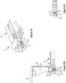
- Figure 2a illustrates a perspective view of a sliding joint such as the sliding joint 110 used in the airframe structure assembly 100 of Figure 1 , according to an example.
- the sliding joint 110 comprises a lug 112 which is configured to be received within an open channel 133 of a seat track, such as the seat track 130 of Figure 1 .
- a portion of the seat track 130 of Figure 1 is shown in Figure 2a .
- a first end 113 of the lug 112 is shown in Figure 2a to comprise an engagement portion 114 to engage the seat track 130.
- the engagement portion 114 comprises a plurality of apertures 115 that engage a plurality of bolts therethrough to secure the engagement portion 114 within the seat track 130.
- a second end 116 of the lug 112 comprises an elongate aperture 117.
- the elongate aperture 117 comprises rounded ends 118, both of which are shown in the cross-sectional side view of Figure 2b .
- the rounded ends 118 accommodate the shape of the oblate shaped slider bushing, thereby allowing the oblate shaped slider bushing to freely move from end to end within the elongate aperture 117 without becoming stuck.
- the elongate aperture 117 is sized and shaped to provide for one dimensional motion of a bushing within. This single dimensional motion accounts for thermal expansion or contraction or bending deflections of the seat track 130 and the flight deck floor panel 140 during flight of the aircraft 200.
- the sliding joint 110 further comprises a clevis 120.
- the clevis 120 comprises an oblate shaped slider bushing 122.
- the elongate aperture 117 of the lug 112 is sized and shaped to receive the oblate shaped slider bushing 122, which slidably secures the clevis 120 to the lug 112.
- the oblate shaped slider bushing 122 is typically made from a strong material that is not prone to quick wear, for example a metal such as steel.
- the oblate shaped slider bushing 122 is formed from corrosion resistant steel.
- the oblate shaped slider bushing 122 is formed from titanium.
- the outer surface of the oblate shaped slider bushing 122 is deemed a wear surface, and the oblate spheroid shape that comprises the bushing increases an area of the wear surface for the slider bushing 122.
- the flattened top and bottom surfaces 121 shown in Figure 2c form the expanded wear surface.
- Figure 2b illustrates a cross-sectional side view of the sliding joint 110 of Figure 1 connected to the seat track 130 and the flight deck floor panel 140 of Figure 1 , according to an example.
- the clevis 120 comprises a platform 124 at a first end of the clevis 120 and a pair of arms 126 (one being shown in Figure 2b ) extending from the platform 124.
- the oblate shaped slider bushing 122 extends through the pair of arms 126.
- the platform 124 is adapted to affix to the flight deck floor panel 140, as shown in Figure 2b .
- the platform 124 may affix directly to the flight deck floor panel or may affix to a stiffener, such as the stiffener 127 shown in Figure 2b .
- the stiffener 127 may be a metal or other rigid structure which may additionally be present behind a vertical flooring panel 128 to structurally support the vertical panel 128.
- the vertical flooring panel 128 covers the step or transition gap between the seat track 130 and the flight deck floor panel 140.
- Figure 2c illustrates a cross-sectional view of an oblate shaped slider bushing of the sliding joint of Figure 2b within the elongated aperture of the lug, according to an example.
- the cross-section is taken along lines A-A of Figure 2b .
- flattened top and bottom surfaces 121 of the slider bushing 122 form an expanded wear surface, which facilitates extension of the life of the bushing.
- Circular-shaped or rounded sides 123 maintain the spheroid shape for the bushing, allowing for smooth translation between ends 118 of the elongated aperture.
- the accumulation of thermal loads and body bending during cycling of a flight can comprise half an inch or more (11 ⁇ 4 cm or more).
- the sliding joint 110 described in detail above allows for improved lifespan of the joint as the elongate aperture is sized and shaped to provide for motion within the elongate aperture of the oblate shaped slider bushing, thereby accounting for thermal expansion or contraction or bending deflections of the passenger seat track and the flight deck floor panel during flight of the aircraft.
- the motion comprises movement in only one dimension.
- Figure 3 illustrates an example series of sliding joints 110 positioned within an aircraft 200, according to an example.
- a plurality of sliding joints such as the sliding joints 110 described with reference to Figures 1-2c , may be located across a width 170 of an aircraft, such as the aircraft 200 of Figure 1 , at the location of transition between the seat track 130 and the flight deck floor panel 140.
- Figure 4 illustrates a perspective and enlarged view of the series of sliding joints 110 of Figure 3 , according to an example.
- Figure 4 shows the stiffener 127 and the vertical panel 128, the clevis 120, and the lug 112 of Figure 2b .
- Figure 5 shows a flowchart of an example of a method 500 for isolating load transfer between a passenger seat track and a flight deck floor panel of an aircraft, according to an example.
- Method 500 shown in Figure 5 presents a method that, for example, could be used with the airframe structure assembly 100 and/or performed by the airframe structure assembly 100 shown in Figure 1 .
- Method 500 includes one or more operations, functions, or actions as illustrated by one or more of blocks 502-508. Although the blocks are illustrated in a sequential order, these blocks may also be performed in parallel, and/or in a different order than those described herein. Also, the various blocks may be combined into fewer blocks, divided into additional blocks, and/or removed based upon the desired implementation.
- the method 500 includes attaching a first end of a lug to the seat track, the lug further comprising a second end having an elongate aperture therethrough.
- the lug may be the same as or similar to the lug 112 and the seat track may be similar to or the same as the seat track 130 described with reference to Figures 1-2b .
- the first end 113 of the lug 112 comprises an engagement portion to engage the seat track 130.
- the first end 113 is attached to the seat track 130 by inserting the first end 113 into a channel or other opening within the seat track 130.
- the first end 113 of the lug 112 may then be secured within the seat track 130 by any of a number of fasteners, such as but not limited to, bolts, screws, and the like.
- the first end 113 of the lug 112 may be formed to adapt to and fit within the geometry.
- the method 500 includes attaching a first end of a clevis to the flight deck floor panel, the first end of the clevis comprising a platform 124 and a pair of arms extending from the platform 124.
- the platform 124 is shown in the example of Figures 2a-b to have a flat surface, which can be affixed directly to the flight deck panel or to componentry attached to the flight deck panel, such as a vertical floor beam or stiffener located behind the vertical floor beam, as shown in Figure 2b .
- the method 500 includes coupling an oblate shaped slider bushing to the pair of arms of the clevis.
- the oblate shaped slider bushing may be the same as or similar to the oblate shaped slider bushing 122 of Figures 2a-c .
- the oblate shaped slider bushing 122 is shown to comprise flattened top and bottom surfaces 121 and circular-shaped or rounded sides 123.
- the method 500 includes receiving the oblate shaped slider bushing within the elongate aperture to secure the clevis to the lug.
- the elongate aperture 117 at the second end 116 of the lug 112 comprises rounded ends 118 in the example shown in Figures 2a-b to accommodate the shape of the oblate shaped slider bushing, thereby allowing the oblate shaped slider bushing to move from end to end within the elongate aperture 117.
- movement of the flight deck floor panel 140 will move the clevis 120 and associated oblate shaped slider bushing 122 in the fore or aft directions within the elongate aperture 117. And in further examples, movement of the seat track 130 will move to the lug in the fore or aft directions.
- Figure 6 shows another method for use with the method 500 shown in Figure 5 , according to an example.
- the method includes translating the oblate shaped slider bushing in forward and aft directions within the elongate aperture during cycling of the aircraft.
- the seat track 130 and the flight deck floor panel 140 may move or jostle. Such movement causes the slider bushing 122 to move in either a forward or an aft direction within the elongate aperture 117.
- the translation of components of the sliding joint assembly all the while accommodating the complex geometry between the seat track 130 and the flight deck floor panel 140, prevents thermal and bending load accumulation between the seat track and the flight deck floor panel during cycling of an aircraft.
- the oblate shape of the bushing provides an expanded surface area of contact of the bushing within an elongated opening of the lug during translation, which prevents wear on the bushing itself and thus further improves the lifespan of the joint.
Landscapes
- Engineering & Computer Science (AREA)
- Aviation & Aerospace Engineering (AREA)
- Mechanical Engineering (AREA)
- Body Structure For Vehicles (AREA)
- Connection Of Plates (AREA)
- Seats For Vehicles (AREA)
Abstract
Description
- The present disclosure generally relates to alleviating load transfer between two floor components of an aircraft, and more particularly for providing a sliding joint for isolating thermal load and bending deflections between a seat track and a flight deck floor panel during cycling of an aircraft.
- In modern commercial passenger aircraft, two or more seats are connected to an undercarriage to form a seat row, and the undercarriage is in turn securely mounted to one or more underlying longitudinally extending tracks. Such seat tracks are connected to a flight deck floor panel, which is located toward the forward end of the aircraft and contains, among other compartments, lavatories and a flight cabin. Often there is a vertical step of at least several inches at the transition between flooring containing the seat track and the flight deck floor panel.
- During cycling of an aircraft, the aircraft motion results in thermal loading and body bending of flooring components. Thermal stresses and body bending can accumulate and transfer via the joints between the seat track and the flight deck floor panel. The thermal and bending loads often reach a magnitude sufficient to cause a noticeable jostle to be transferred between the two sections of the aircraft. Furthermore, these loads can cause a joint to bind up and fatigue.
- An improved system and method capable of isolating thermal loads and body bending between aircraft flooring panels, such as between a passenger seat track and a flight deck floor panel, is desired.
- In one example, a sliding joint for isolating load transfer between a seat track and a flight deck floor panel of an aircraft is described. The sliding joint comprises a lug comprising a first end and a second end opposite the first end, wherein the first end is adapted to attach to the seat track and the second end comprises an elongate aperture. The sliding joint further comprises a clevis comprising an oblate shaped slider bushing that is coupled to the lug.
- In another example, an airframe structure assembly is provided. The airframe structure assembly comprises a seat track, a flight deck floor panel, and a sliding joint. The sliding joint comprises a lug comprising a first end and a second end opposite the first end, wherein the first end is adapted to attach to the seat track and the second end comprises an elongate aperture, and a clevis comprising an oblate shaped slider bushing that is coupled to the lug.
- In another example, a method for isolating load transfer between a passenger seat track and a flight deck floor panel of an aircraft is provided. The method comprises attaching a first end of a lug to the seat track, the lug further comprising a second end having an elongate aperture therethrough, attaching a first end of a clevis to the flight deck floor panel, the first end of the clevis comprising a platform and a pair of arms extending from the platform, coupling an oblate shaped slider bushing to the pair of arms of the clevis, and receiving the oblate shaped slider bushing within the elongate aperture to secure the clevis to the lug.
- The features, functions, and advantages that have been discussed can be achieved independently in various examples or may be combined in yet other examples further details of which can be seen with reference to the following description and drawings.
- The novel features believed characteristic of the illustrative examples are set forth in the appended claims. The illustrative examples, however, as well as a preferred mode of use, further objectives and descriptions thereof, will best be understood by reference to the following detailed description of an illustrative example of the present disclosure when read in conjunction with the accompanying drawings, wherein:
-
Figure 1 illustrates an airframe structure assembly comprising a sliding joint between a seat track and a flight deck floor panel. -
Figure 2a illustrates a perspective view of a sliding joint such as the sliding joint used in the airframe structure assembly ofFigure 1 . -
Figure 2b illustrates a side view of the sliding joint ofFigure 2a assembled to a flight deck floor panel and a seat track. -
Figure 2c illustrates a cross-sectional view of an oblate shaped slider bushing within the lug of the sliding joint ofFigure 2b . -
Figure 3 illustrates an example series of sliding joints positioned within an aircraft. -
Figure 4 illustrates a perspective and enlarged view of the series of sliding joints ofFigure 3 . -
Figure 5 illustrates a method for isolating load transfer between a seat track and a flight deck floor panel of an aircraft. -
Figure 6 illustrates another method for use with the method shown inFigure 5 . - Disclosed examples will now be described more fully hereinafter with reference to the accompanying drawings, in which some, but not all of the disclosed examples are shown. Indeed, several different examples may be described and should not be construed as limited to the examples set forth herein. Rather, these examples are described so that this disclosure will be thorough and complete and will fully convey the scope of the disclosure to those skilled in the art.
- Examples, methods, and systems are described for a sliding joint to isolate load transfer between a seat track and a flight deck floor panel of an aircraft. To this end, a lug positioned within an open channel of a seat track receives a clevis having an oblate shaped bushing, allowing for forward and aft translation of the bushing within an elongated aperture of the lug. Within examples, the clevis has a platform that is adapted to affix to a flight deck floor panel. The translation of components of the sliding joint assembly prevents thermal and bending load accumulation between the seat track and the flight deck floor panel during cycling of an aircraft, while also accommodating the complex geometry which comprises a vertical step between the two surfaces.
- Moreover, the oblate shape of the bushing provides an expanded surface area of contact of the bushing within an elongated opening of the lug during translation, which prevents wear on the bushing itself and thus improves the lifespan of the joint.
- As used herein, a seat track may include any passenger seat track that accommodates one or more seating units of an aircraft. The seating units and seat track comprise standard equipment used throughout the aircraft industry, wherein the seat track includes a plurality of longitudinally spaced apart mounting receptacles to enable the seating units to be positioned at various positions along the seat track. The seat track is formed of a rigid material, such as a metal (e.g., titanium or the like), which facilitates its ability to serve as a mounting platform for seating units.
- As used herein, a flight deck may include an aircraft cockpit, from which the pilot and crew operate the aircraft, and wherein various equipment and controls are located. The flight deck may further include additional rooms and compartments, such as lavatories, food preparation stations, and storage.
- Referring to
Figure 1 , anairframe structure assembly 100 comprising aseat track 130, a flightdeck floor panel 140, and a slidingjoint 110 is illustrated, according to an example. The slidingjoint 110 is positioned between theseat track 130 and the flightdeck floor panel 140. InFigure 1 , the airframe structure assembly is shown within anaircraft 200. - The
aircraft 200 may be a commercial aircraft used to accommodate and transport passengers, wherein the passengers sit onseating units 132 mounted to theseat track 130. - The flight
deck floor panel 140 is shown inFigure 1 to be positioned on a different plane from theseat track 130. In the example ofFigure 1 , the flightdeck floor panel 140 is on a plane that is parallel to and higher than the plane on which theseat track 130 is located. In some examples, the flightdeck floor panel 140 is located on a plane that is 5-10 inches (13-25 cm) or about 5-10 inches (13-25 cm) above theseat track 130. In some examples, the flightdeck floor panel 140 is located 7 inches (18 cm) or about 7 inches (18 cm) above theseat track 130. - The sliding
joint 110 provides the primary structural connection between theseat track 130 and the flightdeck floor panel 140. The slidingjoint 110 may be covered with a vertical panel or floor beam, so as to form a step between theseat track 130 and the flightdeck floor panel 140. The slidingjoint 110, which is described in further detail inFigures 2a-c , provides for free translation in the forward and aft directions. Thus, when one or both of theseat track 130 and the flightdeck floor panel 140 experience jostling or otherwise move during flight, certain components of the sliding joint move as well, while isolating the movement from extending to the other floor panel. -
Figure 2a illustrates a perspective view of a sliding joint such as the slidingjoint 110 used in theairframe structure assembly 100 ofFigure 1 , according to an example. - The sliding
joint 110 comprises alug 112 which is configured to be received within an open channel 133 of a seat track, such as theseat track 130 ofFigure 1 . A portion of theseat track 130 ofFigure 1 is shown inFigure 2a . Afirst end 113 of thelug 112 is shown inFigure 2a to comprise an engagement portion 114 to engage theseat track 130. InFigure 2a , the engagement portion 114 comprises a plurality ofapertures 115 that engage a plurality of bolts therethrough to secure the engagement portion 114 within theseat track 130. - A
second end 116 of thelug 112 comprises anelongate aperture 117. Within examples, theelongate aperture 117 comprisesrounded ends 118, both of which are shown in the cross-sectional side view ofFigure 2b . The rounded ends 118 accommodate the shape of the oblate shaped slider bushing, thereby allowing the oblate shaped slider bushing to freely move from end to end within theelongate aperture 117 without becoming stuck. Theelongate aperture 117 is sized and shaped to provide for one dimensional motion of a bushing within. This single dimensional motion accounts for thermal expansion or contraction or bending deflections of theseat track 130 and the flightdeck floor panel 140 during flight of theaircraft 200. - The sliding joint 110 further comprises a
clevis 120. Theclevis 120 comprises an oblate shapedslider bushing 122. Theelongate aperture 117 of thelug 112 is sized and shaped to receive the oblate shapedslider bushing 122, which slidably secures theclevis 120 to thelug 112. The oblate shapedslider bushing 122 is typically made from a strong material that is not prone to quick wear, for example a metal such as steel. In some examples, the oblate shapedslider bushing 122 is formed from corrosion resistant steel. In other examples, the oblate shapedslider bushing 122 is formed from titanium. - Because there is contact between the oblate shaped
slider bushing 122 and the surfaces defining theelongate aperture 117, the outer surface of the oblate shapedslider bushing 122 is deemed a wear surface, and the oblate spheroid shape that comprises the bushing increases an area of the wear surface for theslider bushing 122. The expanded surface area of contact of the bushing within an elongated opening of the lug during translation, provided by this oblate spheroid shape, prevents wear on the bushing itself and thus improves the lifespan of the joint. The flattened top andbottom surfaces 121 shown inFigure 2c form the expanded wear surface. -
Figure 2b illustrates a cross-sectional side view of the sliding joint 110 ofFigure 1 connected to theseat track 130 and the flightdeck floor panel 140 ofFigure 1 , according to an example. Theclevis 120 comprises a platform 124 at a first end of theclevis 120 and a pair of arms 126 (one being shown inFigure 2b ) extending from the platform 124. The oblate shapedslider bushing 122 extends through the pair ofarms 126. - The platform 124 is adapted to affix to the flight
deck floor panel 140, as shown inFigure 2b . The platform 124 may affix directly to the flight deck floor panel or may affix to a stiffener, such as thestiffener 127 shown inFigure 2b . Thestiffener 127 may be a metal or other rigid structure which may additionally be present behind avertical flooring panel 128 to structurally support thevertical panel 128. Thevertical flooring panel 128 covers the step or transition gap between theseat track 130 and the flightdeck floor panel 140. -
Figure 2c illustrates a cross-sectional view of an oblate shaped slider bushing of the sliding joint ofFigure 2b within the elongated aperture of the lug, according to an example. The cross-section is taken along lines A-A ofFigure 2b . As previously noted, flattened top andbottom surfaces 121 of theslider bushing 122 form an expanded wear surface, which facilitates extension of the life of the bushing. Circular-shaped or roundedsides 123 maintain the spheroid shape for the bushing, allowing for smooth translation between ends 118 of the elongated aperture. - The accumulation of thermal loads and body bending during cycling of a flight can comprise half an inch or more (1¼ cm or more). The sliding joint 110 described in detail above allows for improved lifespan of the joint as the elongate aperture is sized and shaped to provide for motion within the elongate aperture of the oblate shaped slider bushing, thereby accounting for thermal expansion or contraction or bending deflections of the passenger seat track and the flight deck floor panel during flight of the aircraft. The motion comprises movement in only one dimension. Thus, by decreasing accumulation of thermal loads and body bending applied to the joint, which contribute to joint fatigue or binding of the joint during cycling of an aircraft, the lifespan of the joint can be extended.
-
Figure 3 illustrates an example series of slidingjoints 110 positioned within anaircraft 200, according to an example. As shown inFigure 3 , a plurality of sliding joints, such as the slidingjoints 110 described with reference toFigures 1-2c , may be located across awidth 170 of an aircraft, such as theaircraft 200 ofFigure 1 , at the location of transition between theseat track 130 and the flightdeck floor panel 140. -
Figure 4 illustrates a perspective and enlarged view of the series of slidingjoints 110 ofFigure 3 , according to an example.Figure 4 shows thestiffener 127 and thevertical panel 128, theclevis 120, and thelug 112 ofFigure 2b . -
Figure 5 shows a flowchart of an example of amethod 500 for isolating load transfer between a passenger seat track and a flight deck floor panel of an aircraft, according to an example.Method 500 shown inFigure 5 presents a method that, for example, could be used with theairframe structure assembly 100 and/or performed by theairframe structure assembly 100 shown inFigure 1 .Method 500 includes one or more operations, functions, or actions as illustrated by one or more of blocks 502-508. Although the blocks are illustrated in a sequential order, these blocks may also be performed in parallel, and/or in a different order than those described herein. Also, the various blocks may be combined into fewer blocks, divided into additional blocks, and/or removed based upon the desired implementation. - It should be understood that for this and other processes and methods disclosed herein, flowcharts show functionality and operation of certain examples. Alternative examples may include functions executed out of order from that shown or discussed, including substantially concurrent or in reverse order, depending on the functionality involved, as would be understood by those reasonably skilled in the art.
- At
block 502, themethod 500 includes attaching a first end of a lug to the seat track, the lug further comprising a second end having an elongate aperture therethrough. - The lug may be the same as or similar to the
lug 112 and the seat track may be similar to or the same as theseat track 130 described with reference toFigures 1-2b . In the example shown inFigures 2a-b , thefirst end 113 of thelug 112 comprises an engagement portion to engage theseat track 130. Within examples, thefirst end 113 is attached to theseat track 130 by inserting thefirst end 113 into a channel or other opening within theseat track 130. Thefirst end 113 of thelug 112 may then be secured within theseat track 130 by any of a number of fasteners, such as but not limited to, bolts, screws, and the like. Should theseat track 130 comprise a different geometry than the geometry shown in the examples ofFigures 1-2b , thefirst end 113 of thelug 112 may be formed to adapt to and fit within the geometry. - At
block 504, themethod 500 includes attaching a first end of a clevis to the flight deck floor panel, the first end of the clevis comprising a platform 124 and a pair of arms extending from the platform 124. The platform 124 is shown in the example ofFigures 2a-b to have a flat surface, which can be affixed directly to the flight deck panel or to componentry attached to the flight deck panel, such as a vertical floor beam or stiffener located behind the vertical floor beam, as shown inFigure 2b . - At
block 506, themethod 500 includes coupling an oblate shaped slider bushing to the pair of arms of the clevis. The oblate shaped slider bushing may be the same as or similar to the oblate shapedslider bushing 122 ofFigures 2a-c . The oblate shapedslider bushing 122 is shown to comprise flattened top andbottom surfaces 121 and circular-shaped or roundedsides 123. - At
block 508, themethod 500 includes receiving the oblate shaped slider bushing within the elongate aperture to secure the clevis to the lug. Theelongate aperture 117 at thesecond end 116 of thelug 112 comprises rounded ends 118 in the example shown inFigures 2a-b to accommodate the shape of the oblate shaped slider bushing, thereby allowing the oblate shaped slider bushing to move from end to end within theelongate aperture 117. - Within examples, movement of the flight
deck floor panel 140 will move theclevis 120 and associated oblate shapedslider bushing 122 in the fore or aft directions within theelongate aperture 117. And in further examples, movement of theseat track 130 will move to the lug in the fore or aft directions. -
Figure 6 shows another method for use with themethod 500 shown inFigure 5 , according to an example. InFigure 6 , atblock 510, the method includes translating the oblate shaped slider bushing in forward and aft directions within the elongate aperture during cycling of the aircraft. When theaircraft 200 takes off and then proceeds to fly in the air, one or both of theseat track 130 and the flightdeck floor panel 140 may move or jostle. Such movement causes theslider bushing 122 to move in either a forward or an aft direction within theelongate aperture 117. - Within examples, the translation of components of the sliding joint assembly, all the while accommodating the complex geometry between the
seat track 130 and the flightdeck floor panel 140, prevents thermal and bending load accumulation between the seat track and the flight deck floor panel during cycling of an aircraft. The oblate shape of the bushing provides an expanded surface area of contact of the bushing within an elongated opening of the lug during translation, which prevents wear on the bushing itself and thus further improves the lifespan of the joint. - The description of the different advantageous arrangements has been presented for purposes of illustration and description, and is not intended to be exhaustive or limited to the examples in the form disclosed. Many modifications and variations will be apparent to those of ordinary skill in the art. Further, different advantageous examples may describe different advantages as compared to other advantageous examples. The example or examples selected are chosen and described in order to explain the principles of the examples, the practical application, and to enable others of ordinary skill in the art to understand the disclosure for various examples with various modifications as are suited to the particular use contemplated.
- Clause 1: A sliding joint for isolating load transfer between a seat track and a flight deck floor panel of an aircraft comprising a lug comprising a first end and a second end opposite the first end, wherein the first end is adapted to attach to the seat track and the second end comprises an elongate aperture; and a clevis comprising an oblate shaped slider bushing that is coupled to the lug.
- Clause 2: The sliding joint of Clause 1, wherein the elongate aperture of the lug is sized and shaped to receive the oblate shaped slider bushing to slidably secure the clevis to the lug.
- Clause 3: The sliding joint of Clause 2, wherein the elongate aperture comprises rounded ends.
- Clause 4: The sliding joint of any of Clauses 1-3, wherein the first end of the lug comprises an engagement portion to engage the seat track.
- Clause 5: The sliding joint of any of Clauses 1-4, wherein the clevis comprises a platform at a first end of the clevis and a pair of arms extending from the platform.
- Clause 6: The sliding joint of Clause 5, wherein the oblate shaped slider bushing extends through the pair of arms.
- Clause 7: The sliding joint of Clause 6, wherein the oblate shaped slider bushing comprises an oblate spheroid shape, thereby increasing an area of wear surface for the oblate shaped slider bushing.
- Clause 8: The sliding joint of any of Clauses 1-7, wherein a platform of the clevis is adapted to affix to the flight deck floor panel.
- Clause 9: The sliding joint of any of Clauses 1-8, wherein the elongate aperture is sized and shaped to provide for one dimensional motion of the oblate shaped slider bushing within the elongate aperture, thereby accounting for thermal expansion or contraction or bending deflections of the seat track and the flight deck floor panel during flight of the aircraft.
- Clause 10: The sliding joint of Clause 9, wherein the one dimensional motion comprises forward and aft translation of the oblate shaped slider bushing within the elongate aperture.
- Clause 11: An airframe structure assembly comprising a seat track; a flight deck floor panel; and a sliding joint, the sliding joint comprising a lug defining a first end and a second end opposite the first end, wherein the second end comprises an elongate aperture; and a clevis comprising an oblate shaped slider bushing that is coupled to the lug.
- Clause 12: The airframe structure assembly of Clause 11, wherein the first end of the lug is affixed to the seat track.
- Clause 13: The airframe structure assembly of Clause 12, wherein the clevis comprises a first end having a platform and a pair of arms extending from the platform, the first end being affixed to the flight deck floor panel.
- Clause 14: The airframe structure assembly of Clause 13, wherein the oblate shaped slider bushing is coupled to and extends between the pair of arms, and wherein the oblate shaped slider bushing is received within the elongate aperture of the lug.
- Clause 15: The airframe structure assembly of Clause 14, wherein the elongate aperture is sized and shaped to provide for motion within the elongate aperture of the oblate shaped slider bushing, thereby accounting for thermal expansion or contraction or bending deflections of the seat track and the flight deck floor panel during flight of the aircraft.
- Clause 16: The airframe structure assembly of Clause 15, wherein the motion comprises movement in only one dimension.
- Clause 17: The airframe structure assembly of Clause 16, wherein the motion comprises forward and aft translation of the oblate shaped slider bushing within the elongate aperture.
- Clause 18: The airframe structure assembly of any of Clauses 11-17, wherein the oblate shaped slider bushing comprises an oblate spheroid shape.
- Clause 19: A method for isolating load transfer between a passenger seat track and a flight deck floor panel of an aircraft, the method comprising attaching a first end of a lug to the passenger seat track, the lug further comprising a second end having an elongate aperture therethrough; attaching a first end of a clevis to the flight deck floor panel, the first end of the clevis comprising a platform and a pair of arms extending from the platform; coupling an oblate shaped slider bushing to the pair of arms of the clevis; and receiving the oblate shaped slider bushing within the elongate aperture to secure the clevis to the lug.
- Clause 20: The method of Clause 19, further comprising translating the oblate shaped slider bushing in forward and aft directions within the elongate aperture during cycling of the aircraft.
Claims (15)
- An airframe structure assembly (100) comprising:a flight deck floor panel (140);a seat track (130);a sliding joint (110) for isolating load transfer between the seat track (130) and the flight deck floor panel (140) comprising:
a lug (112) comprising a first end (113) and a second end (116) opposite the first end (113), wherein the first end (113) is attached to the seat track (130) and the second end (116) comprises an elongate aperture (117); anda clevis (120) comprising an oblate shaped slider bushing (122) that is coupled to the lug (112). - The airframe structure assembly of claim 1, wherein the clevis comprises a platform at a first end of the clevis and a pair of arms extending from the platform.
- The airframe structure assembly (100) of claim 2, wherein the platform of the clevis is affixed to the flight deck floor panel (140) and, optionally, the first end (113) of the platform is affixed to the flight deck floor panel (140).
- The airframe structure assembly (100) of claim 2 or 3, wherein the oblate shaped slider bushing extends through the pair of arms.
- The airframe structure assembly (100) of claim 4, wherein the oblate shaped slider bushing comprises an oblate spheroid shape, thereby increasing an area of wear surface for the oblate shaped slider bushing.
- The airframe structure assembly (100) of any one of claims 1-5, wherein the elongate aperture (117) of the lug (112) is sized and shaped to receive the oblate shaped slider bushing (122) to slidably secure the clevis (120) to the lug (112).
- The airframe structure assembly (100) of claim 6, wherein the elongate aperture comprises rounded ends.
- The airframe structure assembly (100) of any one of claims 1-7, wherein the first end (113) of the lug (112) comprises an engagement portion (114) that engages the seat track (130).
- The airframe structure assembly (100) of any of claims 1-8, wherein the elongate aperture (117) is sized and shaped to provide for one dimensional motion of the oblate shaped slider bushing within the elongate aperture (117), thereby accounting for thermal expansion or contraction or bending deflections of the seat track and the flight deck floor panel (140) during flight.
- The airframe structure assembly (100) of claim 9, wherein the one dimensional motion comprises forward and aft translation of the oblate shaped slider bushing within the elongate aperture (117).
- The airframe structure assembly (100) of any of claims 1-10, wherein the flight deck floor panel (140) is positioned on a different plane from the seat track (130) and, optionally, the flight deck floor panel (140) is on a plane that is parallel to and higher than the plane on which the seat track (130) is located.
- The airframe structure assembly (100) of any of claims 1-11, wherein the sliding joint (110) provides the primary structural connection between the seat track (130) and the flight deck floor panel (140).
- An aircraft (200) comprising the airframe structure assembly (100) of any of claims 1-12.
- The aircraft (200) of claim 13, wherein the aircraft (200) is a commercial aircraft used to accommodate and transport passengers, and the passengers sit on seating units (132) mounted to the seat track (130).
- A method for isolating load transfer between a seat track (130) and a flight deck floor panel (140) of an aircraft (200), the method comprising:attaching a first end (113) of a lug (112) to the seat track (130), the lug (112) further comprising a second end (116) having an elongate aperture (117) therethrough;attaching a first end of a clevis (120) to the flight deck floor panel (140), the first end of the clevis (120) comprising a platform (124) and a pair of arms (126) extending from the platform (124);coupling an oblate shaped slider bushing (122) to the pair of arms (126) of the clevis (120); andreceiving the oblate shaped slider bushing (122) within the elongate aperture (117) to secure the clevis (120) to the lug (112); and, optionally,translating the oblate shaped slider bushing (122) in forward and aft directions within the elongate aperture (117) during cycling of the aircraft (200).
Applications Claiming Priority (1)
| Application Number | Priority Date | Filing Date | Title |
|---|---|---|---|
| US16/871,021 US11511863B2 (en) | 2020-05-10 | 2020-05-10 | Sliding joint for load alleviation |
Publications (2)
| Publication Number | Publication Date |
|---|---|
| EP3909845A1 true EP3909845A1 (en) | 2021-11-17 |
| EP3909845B1 EP3909845B1 (en) | 2023-08-09 |
Family
ID=75302361
Family Applications (1)
| Application Number | Title | Priority Date | Filing Date |
|---|---|---|---|
| EP21165980.0A Active EP3909845B1 (en) | 2020-05-10 | 2021-03-30 | Airframe assembly with sliding joint for load allevation |
Country Status (5)
| Country | Link |
|---|---|
| US (1) | US11511863B2 (en) |
| EP (1) | EP3909845B1 (en) |
| JP (1) | JP7687856B2 (en) |
| CN (1) | CN113636084B (en) |
| CA (1) | CA3111917C (en) |
Families Citing this family (2)
| Publication number | Priority date | Publication date | Assignee | Title |
|---|---|---|---|---|
| FR3159589A1 (en) * | 2024-02-22 | 2025-08-29 | Airbus Operations (Sas) | Adjustable floor module for a fuselage portion of an aircraft and method of integrating such a floor module. |
| EP4606704A1 (en) * | 2024-02-23 | 2025-08-27 | AIRBUS HELICOPTERS DEUTSCHLAND GmbH | A seat beam for a rotary-wing aircraft adapted for receiving seat posts of a seat bench device |
Citations (4)
| Publication number | Priority date | Publication date | Assignee | Title |
|---|---|---|---|---|
| EP0922632A2 (en) * | 1997-12-09 | 1999-06-16 | McDonnell Douglas Corporation | Aircraft seat track fitting |
| US20090294587A1 (en) * | 2006-04-20 | 2009-12-03 | Airbus France | Aircraft floor, use of said floor and aircraft section fitted with said floor |
| US20120074259A1 (en) * | 2009-01-29 | 2012-03-29 | Benoit Demont | Airframe including crossmembers for fixing seats |
| ES2441425A1 (en) * | 2012-01-13 | 2014-02-04 | Figeac Aero, S.A. | Seat rail, its manufacturing procedure and obtained floor (Machine-translation by Google Translate, not legally binding) |
Family Cites Families (10)
| Publication number | Priority date | Publication date | Assignee | Title |
|---|---|---|---|---|
| DE3141869C2 (en) * | 1981-10-22 | 1984-02-02 | Messerschmitt-Bölkow-Blohm GmbH, 8000 München | Floor construction for the upper hold of an aircraft |
| FR2705314B1 (en) * | 1993-05-14 | 1995-07-13 | Sicma Aero Seat | Air transport device seat base comprising an attached energy absorption device. |
| FR2872781B1 (en) | 2004-07-08 | 2007-10-05 | Airbus France Sas | FLOOR FOR AIRCRAFT |
| DE102005042403B8 (en) * | 2005-09-06 | 2008-01-10 | Airbus Deutschland Gmbh | Modular seating system for a vehicle |
| US8376276B2 (en) * | 2008-08-14 | 2013-02-19 | Airbus Operations Gmbh | Load introduction structure, in particular a lining frame, for an aircraft |
| FR2974615B1 (en) * | 2011-04-26 | 2014-05-30 | Airbus Operations Sas | CROSS STRUCTURE FOR USE IN CARRYING OUT AN AIRCRAFT FLOOR AND AIRCRAFT FLOOR USING SUCH A TRAVERSE |
| EP3526120B1 (en) * | 2016-10-12 | 2021-12-01 | B/E Aerospace, Inc. | Contoured class divider |
| CN106672197B (en) | 2016-12-26 | 2019-03-19 | 中国航空工业集团公司西安飞机设计研究所 | A kind of cargo deck stringer and block wall connection structure |
| US11338922B2 (en) * | 2017-09-12 | 2022-05-24 | Rockwell Collins, Inc. | Tracking base assembly for aircraft seat |
| US10899458B2 (en) * | 2018-05-21 | 2021-01-26 | The Boeing Company | Sleep systems for aircraft |
-
2020
- 2020-05-10 US US16/871,021 patent/US11511863B2/en active Active
-
2021
- 2021-03-11 CA CA3111917A patent/CA3111917C/en active Active
- 2021-03-30 EP EP21165980.0A patent/EP3909845B1/en active Active
- 2021-05-07 JP JP2021078955A patent/JP7687856B2/en active Active
- 2021-05-08 CN CN202110501911.2A patent/CN113636084B/en active Active
Patent Citations (4)
| Publication number | Priority date | Publication date | Assignee | Title |
|---|---|---|---|---|
| EP0922632A2 (en) * | 1997-12-09 | 1999-06-16 | McDonnell Douglas Corporation | Aircraft seat track fitting |
| US20090294587A1 (en) * | 2006-04-20 | 2009-12-03 | Airbus France | Aircraft floor, use of said floor and aircraft section fitted with said floor |
| US20120074259A1 (en) * | 2009-01-29 | 2012-03-29 | Benoit Demont | Airframe including crossmembers for fixing seats |
| ES2441425A1 (en) * | 2012-01-13 | 2014-02-04 | Figeac Aero, S.A. | Seat rail, its manufacturing procedure and obtained floor (Machine-translation by Google Translate, not legally binding) |
Also Published As
| Publication number | Publication date |
|---|---|
| CA3111917C (en) | 2025-12-16 |
| US11511863B2 (en) | 2022-11-29 |
| CN113636084A (en) | 2021-11-12 |
| JP7687856B2 (en) | 2025-06-03 |
| EP3909845B1 (en) | 2023-08-09 |
| JP2022000366A (en) | 2022-01-04 |
| US20210347487A1 (en) | 2021-11-11 |
| CN113636084B (en) | 2025-10-03 |
| CA3111917A1 (en) | 2021-11-10 |
Similar Documents
| Publication | Publication Date | Title |
|---|---|---|
| US20180016009A1 (en) | Upper Mounting Apparatus for Retaining Aircraft Monuments | |
| US20060249616A1 (en) | Payload to Support Track Interface and Fitting Apparatus and Methods | |
| US11560072B2 (en) | Seat track covering systems and methods | |
| EP3527486B1 (en) | Apparatus for adapting aircraft floors and related methods | |
| US7195201B2 (en) | Adaptable payload enabling architecture | |
| CA3111917C (en) | Sliding joint for load alleviation | |
| US7232095B2 (en) | Overhead rest assembly | |
| US20190118947A1 (en) | Systems and methods for adaptively positioning a cross-aisle curtain header assembly within a vehicle | |
| US20200307806A1 (en) | Seat adjustment system and method | |
| EP3231703B1 (en) | Truss structure | |
| EP3517435B1 (en) | Adjustable swivelling passenger seat assembly | |
| EP3755625B1 (en) | Separable multiple-piece frame assembly | |
| EP4186780A1 (en) | Vehicle cabin sidewall-to-floor coupling assembly and method of assembly | |
| US10926881B2 (en) | Seat adjustment system and method | |
| US11472553B2 (en) | Ceiling retaining assemblies and methods for an internal cabin of a vehicle | |
| US11987362B2 (en) | Galley cart securing systems and methods | |
| US11866176B2 (en) | Variable reclination backrest for a seat assembly | |
| US20260015086A1 (en) | System and method for securing a seat assembly to seat tracks within an internal cabin of a vehicle | |
| US20240253789A1 (en) | Transformable seat systems and methods for an internal cabin of an aircraft | |
| EP3995397B1 (en) | Cargo handling system |
Legal Events
| Date | Code | Title | Description |
|---|---|---|---|
| PUAI | Public reference made under article 153(3) epc to a published international application that has entered the european phase |
Free format text: ORIGINAL CODE: 0009012 |
|
| STAA | Information on the status of an ep patent application or granted ep patent |
Free format text: STATUS: THE APPLICATION HAS BEEN PUBLISHED |
|
| AK | Designated contracting states |
Kind code of ref document: A1 Designated state(s): AL AT BE BG CH CY CZ DE DK EE ES FI FR GB GR HR HU IE IS IT LI LT LU LV MC MK MT NL NO PL PT RO RS SE SI SK SM TR |
|
| B565 | Issuance of search results under rule 164(2) epc |
Effective date: 20210902 |
|
| STAA | Information on the status of an ep patent application or granted ep patent |
Free format text: STATUS: REQUEST FOR EXAMINATION WAS MADE |
|
| 17P | Request for examination filed |
Effective date: 20220503 |
|
| RBV | Designated contracting states (corrected) |
Designated state(s): AL AT BE BG CH CY CZ DE DK EE ES FI FR GB GR HR HU IE IS IT LI LT LU LV MC MK MT NL NO PL PT RO RS SE SI SK SM TR |
|
| REG | Reference to a national code |
Ref country code: DE Ref legal event code: R079 Free format text: PREVIOUS MAIN CLASS: B64C0001200000 Ipc: B64C0001180000 Ref document number: 602021004070 Country of ref document: DE |
|
| GRAP | Despatch of communication of intention to grant a patent |
Free format text: ORIGINAL CODE: EPIDOSNIGR1 |
|
| RAP3 | Party data changed (applicant data changed or rights of an application transferred) |
Owner name: THE BOEING COMPANY |
|
| STAA | Information on the status of an ep patent application or granted ep patent |
Free format text: STATUS: GRANT OF PATENT IS INTENDED |
|
| RIC1 | Information provided on ipc code assigned before grant |
Ipc: B64D 11/06 20060101ALI20230308BHEP Ipc: B64C 1/18 20060101AFI20230308BHEP |
|
| INTG | Intention to grant announced |
Effective date: 20230323 |
|
| GRAS | Grant fee paid |
Free format text: ORIGINAL CODE: EPIDOSNIGR3 |
|
| GRAA | (expected) grant |
Free format text: ORIGINAL CODE: 0009210 |
|
| STAA | Information on the status of an ep patent application or granted ep patent |
Free format text: STATUS: THE PATENT HAS BEEN GRANTED |
|
| P01 | Opt-out of the competence of the unified patent court (upc) registered |
Effective date: 20230612 |
|
| AK | Designated contracting states |
Kind code of ref document: B1 Designated state(s): AL AT BE BG CH CY CZ DE DK EE ES FI FR GB GR HR HU IE IS IT LI LT LU LV MC MK MT NL NO PL PT RO RS SE SI SK SM TR |
|
| REG | Reference to a national code |
Ref country code: GB Ref legal event code: FG4D |
|
| REG | Reference to a national code |
Ref country code: CH Ref legal event code: EP |
|
| REG | Reference to a national code |
Ref country code: IE Ref legal event code: FG4D |
|
| REG | Reference to a national code |
Ref country code: DE Ref legal event code: R096 Ref document number: 602021004070 Country of ref document: DE |
|
| REG | Reference to a national code |
Ref country code: LT Ref legal event code: MG9D |
|
| REG | Reference to a national code |
Ref country code: NL Ref legal event code: MP Effective date: 20230809 |
|
| REG | Reference to a national code |
Ref country code: AT Ref legal event code: MK05 Ref document number: 1597255 Country of ref document: AT Kind code of ref document: T Effective date: 20230809 |
|
| PG25 | Lapsed in a contracting state [announced via postgrant information from national office to epo] |
Ref country code: GR Free format text: LAPSE BECAUSE OF FAILURE TO SUBMIT A TRANSLATION OF THE DESCRIPTION OR TO PAY THE FEE WITHIN THE PRESCRIBED TIME-LIMIT Effective date: 20231110 |
|
| PG25 | Lapsed in a contracting state [announced via postgrant information from national office to epo] |
Ref country code: IS Free format text: LAPSE BECAUSE OF FAILURE TO SUBMIT A TRANSLATION OF THE DESCRIPTION OR TO PAY THE FEE WITHIN THE PRESCRIBED TIME-LIMIT Effective date: 20231209 |
|
| PG25 | Lapsed in a contracting state [announced via postgrant information from national office to epo] |
Ref country code: SE Free format text: LAPSE BECAUSE OF FAILURE TO SUBMIT A TRANSLATION OF THE DESCRIPTION OR TO PAY THE FEE WITHIN THE PRESCRIBED TIME-LIMIT Effective date: 20230809 Ref country code: RS Free format text: LAPSE BECAUSE OF FAILURE TO SUBMIT A TRANSLATION OF THE DESCRIPTION OR TO PAY THE FEE WITHIN THE PRESCRIBED TIME-LIMIT Effective date: 20230809 Ref country code: PT Free format text: LAPSE BECAUSE OF FAILURE TO SUBMIT A TRANSLATION OF THE DESCRIPTION OR TO PAY THE FEE WITHIN THE PRESCRIBED TIME-LIMIT Effective date: 20231211 Ref country code: NO Free format text: LAPSE BECAUSE OF FAILURE TO SUBMIT A TRANSLATION OF THE DESCRIPTION OR TO PAY THE FEE WITHIN THE PRESCRIBED TIME-LIMIT Effective date: 20231109 Ref country code: NL Free format text: LAPSE BECAUSE OF FAILURE TO SUBMIT A TRANSLATION OF THE DESCRIPTION OR TO PAY THE FEE WITHIN THE PRESCRIBED TIME-LIMIT Effective date: 20230809 Ref country code: LV Free format text: LAPSE BECAUSE OF FAILURE TO SUBMIT A TRANSLATION OF THE DESCRIPTION OR TO PAY THE FEE WITHIN THE PRESCRIBED TIME-LIMIT Effective date: 20230809 Ref country code: LT Free format text: LAPSE BECAUSE OF FAILURE TO SUBMIT A TRANSLATION OF THE DESCRIPTION OR TO PAY THE FEE WITHIN THE PRESCRIBED TIME-LIMIT Effective date: 20230809 Ref country code: IS Free format text: LAPSE BECAUSE OF FAILURE TO SUBMIT A TRANSLATION OF THE DESCRIPTION OR TO PAY THE FEE WITHIN THE PRESCRIBED TIME-LIMIT Effective date: 20231209 Ref country code: HR Free format text: LAPSE BECAUSE OF FAILURE TO SUBMIT A TRANSLATION OF THE DESCRIPTION OR TO PAY THE FEE WITHIN THE PRESCRIBED TIME-LIMIT Effective date: 20230809 Ref country code: GR Free format text: LAPSE BECAUSE OF FAILURE TO SUBMIT A TRANSLATION OF THE DESCRIPTION OR TO PAY THE FEE WITHIN THE PRESCRIBED TIME-LIMIT Effective date: 20231110 Ref country code: FI Free format text: LAPSE BECAUSE OF FAILURE TO SUBMIT A TRANSLATION OF THE DESCRIPTION OR TO PAY THE FEE WITHIN THE PRESCRIBED TIME-LIMIT Effective date: 20230809 Ref country code: AT Free format text: LAPSE BECAUSE OF FAILURE TO SUBMIT A TRANSLATION OF THE DESCRIPTION OR TO PAY THE FEE WITHIN THE PRESCRIBED TIME-LIMIT Effective date: 20230809 |
|
| PG25 | Lapsed in a contracting state [announced via postgrant information from national office to epo] |
Ref country code: PL Free format text: LAPSE BECAUSE OF FAILURE TO SUBMIT A TRANSLATION OF THE DESCRIPTION OR TO PAY THE FEE WITHIN THE PRESCRIBED TIME-LIMIT Effective date: 20230809 |
|
| PG25 | Lapsed in a contracting state [announced via postgrant information from national office to epo] |
Ref country code: ES Free format text: LAPSE BECAUSE OF FAILURE TO SUBMIT A TRANSLATION OF THE DESCRIPTION OR TO PAY THE FEE WITHIN THE PRESCRIBED TIME-LIMIT Effective date: 20230809 |
|
| PG25 | Lapsed in a contracting state [announced via postgrant information from national office to epo] |
Ref country code: SM Free format text: LAPSE BECAUSE OF FAILURE TO SUBMIT A TRANSLATION OF THE DESCRIPTION OR TO PAY THE FEE WITHIN THE PRESCRIBED TIME-LIMIT Effective date: 20230809 Ref country code: RO Free format text: LAPSE BECAUSE OF FAILURE TO SUBMIT A TRANSLATION OF THE DESCRIPTION OR TO PAY THE FEE WITHIN THE PRESCRIBED TIME-LIMIT Effective date: 20230809 Ref country code: ES Free format text: LAPSE BECAUSE OF FAILURE TO SUBMIT A TRANSLATION OF THE DESCRIPTION OR TO PAY THE FEE WITHIN THE PRESCRIBED TIME-LIMIT Effective date: 20230809 Ref country code: EE Free format text: LAPSE BECAUSE OF FAILURE TO SUBMIT A TRANSLATION OF THE DESCRIPTION OR TO PAY THE FEE WITHIN THE PRESCRIBED TIME-LIMIT Effective date: 20230809 Ref country code: DK Free format text: LAPSE BECAUSE OF FAILURE TO SUBMIT A TRANSLATION OF THE DESCRIPTION OR TO PAY THE FEE WITHIN THE PRESCRIBED TIME-LIMIT Effective date: 20230809 Ref country code: CZ Free format text: LAPSE BECAUSE OF FAILURE TO SUBMIT A TRANSLATION OF THE DESCRIPTION OR TO PAY THE FEE WITHIN THE PRESCRIBED TIME-LIMIT Effective date: 20230809 Ref country code: SK Free format text: LAPSE BECAUSE OF FAILURE TO SUBMIT A TRANSLATION OF THE DESCRIPTION OR TO PAY THE FEE WITHIN THE PRESCRIBED TIME-LIMIT Effective date: 20230809 |
|
| REG | Reference to a national code |
Ref country code: DE Ref legal event code: R097 Ref document number: 602021004070 Country of ref document: DE |
|
| PG25 | Lapsed in a contracting state [announced via postgrant information from national office to epo] |
Ref country code: IT Free format text: LAPSE BECAUSE OF FAILURE TO SUBMIT A TRANSLATION OF THE DESCRIPTION OR TO PAY THE FEE WITHIN THE PRESCRIBED TIME-LIMIT Effective date: 20230809 |
|
| PLBE | No opposition filed within time limit |
Free format text: ORIGINAL CODE: 0009261 |
|
| STAA | Information on the status of an ep patent application or granted ep patent |
Free format text: STATUS: NO OPPOSITION FILED WITHIN TIME LIMIT |
|
| 26N | No opposition filed |
Effective date: 20240513 |
|
| PG25 | Lapsed in a contracting state [announced via postgrant information from national office to epo] |
Ref country code: SI Free format text: LAPSE BECAUSE OF FAILURE TO SUBMIT A TRANSLATION OF THE DESCRIPTION OR TO PAY THE FEE WITHIN THE PRESCRIBED TIME-LIMIT Effective date: 20230809 |
|
| REG | Reference to a national code |
Ref country code: CH Ref legal event code: PL |
|
| PG25 | Lapsed in a contracting state [announced via postgrant information from national office to epo] |
Ref country code: BG Free format text: LAPSE BECAUSE OF FAILURE TO SUBMIT A TRANSLATION OF THE DESCRIPTION OR TO PAY THE FEE WITHIN THE PRESCRIBED TIME-LIMIT Effective date: 20230809 |
|
| PG25 | Lapsed in a contracting state [announced via postgrant information from national office to epo] |
Ref country code: LU Free format text: LAPSE BECAUSE OF NON-PAYMENT OF DUE FEES Effective date: 20240330 |
|
| PG25 | Lapsed in a contracting state [announced via postgrant information from national office to epo] |
Ref country code: MC Free format text: LAPSE BECAUSE OF FAILURE TO SUBMIT A TRANSLATION OF THE DESCRIPTION OR TO PAY THE FEE WITHIN THE PRESCRIBED TIME-LIMIT Effective date: 20230809 |
|
| PG25 | Lapsed in a contracting state [announced via postgrant information from national office to epo] |
Ref country code: MC Free format text: LAPSE BECAUSE OF FAILURE TO SUBMIT A TRANSLATION OF THE DESCRIPTION OR TO PAY THE FEE WITHIN THE PRESCRIBED TIME-LIMIT Effective date: 20230809 Ref country code: LU Free format text: LAPSE BECAUSE OF NON-PAYMENT OF DUE FEES Effective date: 20240330 Ref country code: BG Free format text: LAPSE BECAUSE OF FAILURE TO SUBMIT A TRANSLATION OF THE DESCRIPTION OR TO PAY THE FEE WITHIN THE PRESCRIBED TIME-LIMIT Effective date: 20230809 |
|
| REG | Reference to a national code |
Ref country code: BE Ref legal event code: MM Effective date: 20240331 |
|
| PG25 | Lapsed in a contracting state [announced via postgrant information from national office to epo] |
Ref country code: BE Free format text: LAPSE BECAUSE OF NON-PAYMENT OF DUE FEES Effective date: 20240331 |
|
| PG25 | Lapsed in a contracting state [announced via postgrant information from national office to epo] |
Ref country code: IE Free format text: LAPSE BECAUSE OF NON-PAYMENT OF DUE FEES Effective date: 20240330 |
|
| PG25 | Lapsed in a contracting state [announced via postgrant information from national office to epo] |
Ref country code: IE Free format text: LAPSE BECAUSE OF NON-PAYMENT OF DUE FEES Effective date: 20240330 Ref country code: BE Free format text: LAPSE BECAUSE OF NON-PAYMENT OF DUE FEES Effective date: 20240331 Ref country code: CH Free format text: LAPSE BECAUSE OF NON-PAYMENT OF DUE FEES Effective date: 20240331 |
|
| PG25 | Lapsed in a contracting state [announced via postgrant information from national office to epo] |
Ref country code: CY Free format text: LAPSE BECAUSE OF FAILURE TO SUBMIT A TRANSLATION OF THE DESCRIPTION OR TO PAY THE FEE WITHIN THE PRESCRIBED TIME-LIMIT; INVALID AB INITIO Effective date: 20210330 |
|
| PG25 | Lapsed in a contracting state [announced via postgrant information from national office to epo] |
Ref country code: HU Free format text: LAPSE BECAUSE OF FAILURE TO SUBMIT A TRANSLATION OF THE DESCRIPTION OR TO PAY THE FEE WITHIN THE PRESCRIBED TIME-LIMIT; INVALID AB INITIO Effective date: 20210330 |
|
| PG25 | Lapsed in a contracting state [announced via postgrant information from national office to epo] |
Ref country code: TR Free format text: LAPSE BECAUSE OF FAILURE TO SUBMIT A TRANSLATION OF THE DESCRIPTION OR TO PAY THE FEE WITHIN THE PRESCRIBED TIME-LIMIT Effective date: 20230809 |
|
| PGFP | Annual fee paid to national office [announced via postgrant information from national office to epo] |
Ref country code: GB Payment date: 20260327 Year of fee payment: 6 |
|
| PGFP | Annual fee paid to national office [announced via postgrant information from national office to epo] |
Ref country code: DE Payment date: 20260327 Year of fee payment: 6 |
|
| PGFP | Annual fee paid to national office [announced via postgrant information from national office to epo] |
Ref country code: FR Payment date: 20260325 Year of fee payment: 6 |