EP3909827A1 - Door leaf for railroad vehicle, fastening structure, and method of manufacturing door leaf for railroad vehicle - Google Patents
Door leaf for railroad vehicle, fastening structure, and method of manufacturing door leaf for railroad vehicle Download PDFInfo
- Publication number
- EP3909827A1 EP3909827A1 EP21167620.0A EP21167620A EP3909827A1 EP 3909827 A1 EP3909827 A1 EP 3909827A1 EP 21167620 A EP21167620 A EP 21167620A EP 3909827 A1 EP3909827 A1 EP 3909827A1
- Authority
- EP
- European Patent Office
- Prior art keywords
- tapping screw
- tapping
- walls
- prepared hole
- contact region
- Prior art date
- Legal status (The legal status is an assumption and is not a legal conclusion. Google has not performed a legal analysis and makes no representation as to the accuracy of the status listed.)
- Granted
Links
Images




Classifications
-
- B—PERFORMING OPERATIONS; TRANSPORTING
- B61—RAILWAYS
- B61D—BODY DETAILS OR KINDS OF RAILWAY VEHICLES
- B61D19/00—Door arrangements specially adapted for rail vehicles
- B61D19/02—Door arrangements specially adapted for rail vehicles for carriages
-
- B—PERFORMING OPERATIONS; TRANSPORTING
- B61—RAILWAYS
- B61D—BODY DETAILS OR KINDS OF RAILWAY VEHICLES
- B61D19/00—Door arrangements specially adapted for rail vehicles
-
- F—MECHANICAL ENGINEERING; LIGHTING; HEATING; WEAPONS; BLASTING
- F16—ENGINEERING ELEMENTS AND UNITS; GENERAL MEASURES FOR PRODUCING AND MAINTAINING EFFECTIVE FUNCTIONING OF MACHINES OR INSTALLATIONS; THERMAL INSULATION IN GENERAL
- F16B—DEVICES FOR FASTENING OR SECURING CONSTRUCTIONAL ELEMENTS OR MACHINE PARTS TOGETHER, e.g. NAILS, BOLTS, CIRCLIPS, CLAMPS, CLIPS OR WEDGES; JOINTS OR JOINTING
- F16B25/00—Screws that cut thread in the body into which they are screwed, e.g. wood screws
- F16B25/10—Screws performing an additional function to thread-forming, e.g. drill screws or self-piercing screws
- F16B25/106—Screws performing an additional function to thread-forming, e.g. drill screws or self-piercing screws by means of a self-piercing screw-point, i.e. without removing material
Definitions
- the present invention relates to a door leaf for a railroad vehicle, a fastening structure, and a method of manufacturing a door leaf for a railroad vehicle.
- Conventional door leaves for railroad vehicles include a frame constituted by an upper edge frame, a lower edge frame, a leading edge frame, and a trailing edge frame (see, for example, Japanese Laid-Open Patent Publication No. 4-57481 ("the '481 Publication").
- the leading and trailing edge frames extend in the vertical direction, which is the longitudinal direction of the door leaf, and the upper and lower edge frames extend in the horizontal direction, which is the transverse direction of the door leaf.
- the door leaf includes inside and outside plates respectively mounted to the inside and outside surfaces of the frame, which respectively face the inside and outside of the railroad vehicle.
- the edge frames constituting the frame of the door leaf are welded to each other.
- the welding may cause distortion. This necessitates correction to satisfy the required accuracy and thus requires work.
- the same problems arise not only in door leaves but also in any products as long as they have parts that need to be connected together.
- the present invention is made in light of the above, and one object thereof is to provide a door leaf for a railroad vehicle, a fastening structure, and a method of manufacturing a door leaf for a railroad vehicle, which can provide for a readily manufacturable door leaf.
- a door leaf for a railroad vehicle includes a first member, a second member, and a tapping screw.
- the tapping screw is to be screwed into a prepared hole provided in the second member while tapping the prepared hole, so that the tapping screw fastens together the first and second members.
- Walls defining the prepared hole in the second member have, in a plane orthogonal to an axial direction of the tapping screw, a non-contact region where the walls do not touch the tapping screw.
- the tightening torque increases to such a degree that the tapping screw can no longer be tightened before the tapping screw is completely screwed in.
- the prepared hole is not tapped along the entire circumference thereof but has a non-contact region where the walls defining the prepared hole do not touch the tapping screw and thus are not tapped. This can reduce the tightening torque produced when the tapping screw is tightened. Accordingly, the tapping screw can be used to fasten together the first and second members. As a result, the railroad vehicle door leaf can be readily manufactured.
- the non-contact region is positioned outside an imaginary circle defining a major diameter of the tapping screw.
- the walls defining the prepared hole have, in the plane orthogonal to the axial direction of the tapping screw, a contact region where the walls touch the tapping screw and that, of the walls in the contact region, one or more walls extending in a circumferential direction of the tapping screw are, in the plane orthogonal to the axial direction of the tapping screw, parallel to a circumference of an imaginary circle defining a major diameter of the tapping screw and centered on a center of the prepared hole.
- the walls defining the prepared hole have, in the plane orthogonal to the axial direction of the tapping screw, a contact region where the walls touch the tapping screw, and that a wall surface in the contact region has, in the plane orthogonal to the axial direction of the tapping screw, a portion outside an imaginary circle defining a minor diameter of the tapping screw and centered on a center of the prepared hole.
- the walls defining the prepared hole are arranged in a point-symmetric manner and centered on a central axis of the prepared hole.
- the non-contact region accounts for, in the plane orthogonal to the axial direction of the tapping screw, 20% to 80% of a circumference of an imaginary circle defining a major diameter of the tapping screw.
- a not-to-be-tapped volume accounts for 20% to 80%.
- the walls defining the prepared hole are divided into:
- the non-contact region is provided in a partial region in the axial direction of the tapping screw.
- an accommodating portion is further provided for accommodating chips produced during tapping by the tapping screw.
- the second member having the prepared hole provided therein is extrusion-molded.
- the door leaf includes a frame made up by vertical and horizontal frames, one of the first and second members is the vertical frame and the other of the first and second members is the horizontal frame.
- the first member is the vertical frame and the second member is the horizontal frame.
- a fastening structure for fastening together a first member and a second member.
- the fastening structure includes a tapping screw to be screwed into a prepared hole provided in the second member while tapping the prepared hole, so that the tapping screw fastens together the first and second members.
- Walls defining the prepared hole in the second member have, in a plane orthogonal to an axial direction of the tapping screw, a non-contact region where the walls do not touch the tapping screw.
- the tightening torque increases to such a degree that the tapping screw can no longer be tightened before the tapping screw is completely screwed in.
- the prepared hole is not tapped along the entire circumference thereof but has a non-contact region where the walls defining the prepared hole do not touch the tapping screw and thus are not tapped. This can reduce the tightening torque produced when the tapping screw is tightened. Accordingly, the tapping screw can be used to fasten together the first and second members. As a result, the fastening structure can simplify the manufacturing process.
- the door leaf includes a first member and a second member.
- the second member is provided with a prepared hole into which a tapping screw is to be screwed.
- Walls defining the prepared hole have, in a plane orthogonal to an axial direction of the tapping screw, a non-contact region where the walls do not touch the tapping screw.
- the method includes fastening together the first and second members by screwing the tapping screw into the prepared hole in the second member while the tapping screw is tapping the prepared hole.
- the tightening torque increases to such a degree that the tapping screw can no longer be tightened before the tapping screw is completely screwed in.
- the prepared hole is not tapped along the entire circumference thereof but has a non-contact region where the walls defining the prepared hole do not touch the tapping screw and thus are not tapped. This can reduce the tightening torque produced when the tapping screw is tightened. Accordingly, the tapping screw can be used to fasten together the first and second members. As a result, the railroad vehicle door leaf can be readily manufactured.
- the door leaf is used for a sliding door of a railroad vehicle.
- the left side of a door leaf 10 is a trailing edge 11, and the right side of the door leaf 10 is a leading edge 12.
- the trailing and leading edges 11 and 12 have the same structure.
- the longitudinal section of the door leaf 10 is curved at its vertically lower portion toward the inside of the railroad vehicle.
- the door leaf 10 includes a frame 20 and surface plates 13 serving as panels or underlying boards and joined to the surfaces of the frame 20.
- the frame 20 includes vertical frames 21 and horizontal frames 22 connected to the vertical frames 21 orthogonally to the vertical frames 21.
- the vertical and horizontal frames 21 and 22 are respectively referred to as first and second members.
- the vertical frames 21 are a part of the frame 20 extending in the vertical direction of the door leaf 10.
- the horizontal frames 22 are a part of the frame 20 extending in the horizontal direction of the door leaf 10.
- the frame 20 includes two vertical frames 21 and two horizontal frames 22, which together form a quadrilateral frame.
- the surface plates 13 are sticked using an adhesive onto the surfaces of the frame 20, which are shown on the lower and upper parts in the drawing. In other words, the frame 20 is sandwiched between the two surface plates 13.
- the vertical frames 21 are extruded molded members shaped like a square cylinder and made of aluminum and made via extrusion molding.
- the horizontal frames 22 are extruded molded members shaped like a square rod and made of aluminum and made via extrusion molding.
- the vertical and horizontal frames 21 and 22 are fastened together by a tapping screw 40.
- the tapping screw 40 penetrates the vertical frame 21 and is screwed into a prepared hole 30 provided in the horizontal frame 22 while tapping the prepared hole 30, so that the tapping screw 40 fastens together the vertical and horizontal frames 21 and 22.
- the vertical frame 21 has a first through hole 21A, through which a screw head 41 of the tapping screw 40 can pass, and a second through hole 21B, through which a threaded portion 42 of the tapping screw 40 can pass, formed therein.
- the second through hole 21B is sized such that the screw head 41 of the tapping screw 40 does not move through it.
- the entire portion of the tapping screw 40 penetrates the first through hole 21A, but only the threaded portion 42 penetrates the second through hole 21B.
- the vertical frame 21 is sandwiched and fastened between the screw head 41 of the tapping screw 40 and the horizontal frame 22. In other words, the vertical and horizontal frames 21 and 22 are fastened together via a fastening structure including the tapping screw 40
- the horizontal frame 22 is a member defining a first space 22A, a second space 22B, and a third space 22C.
- the horizontal frame 22 has, between the first space 22A and the second space 22B, the prepared hole 30, into which the tapping screw 40 is to be screwed. As formed by extrusion molding, the prepared hole 30 entirely extends through the horizontal frame 22.
- the tapping screw 40 has the screw head 41 and the threaded portion 42.
- the screw head 41 is of a truss type.
- the tapping screw 40 is a type-B tapping screw with a coarse pitch, in which the threaded portion 42 has a blunt tip.
- the length of the threaded portion 42 is referred to as a screw length L. Since the prepared hole 30 extends through the horizontal frame 22, the axial length of the prepared hole 30 is greater than the screw length L.
- the major diameter DA represents the diameter of the imaginary co-axial cylinder that touches the crests of the threaded portion 42, and the minor diameter DB represents the diameter of the imaginary co-axial cylinder that touches the roots of the threaded portion 42.
- the walls defining the prepared hole 30 in the horizontal frame 22 are divided into a contact region A1 where the walls are to touch the tapping screw 40 and a non-contact region A2 where the walls are not to touch the tapping screw 40.
- the contact region A1 is, in the plane orthogonal to the axial direction of the tapping screw 40, where the walls defining the prepared hole 30 are positioned inside the alternate long and two short dashes line representing the imaginary circle defining the major diameter DA of the tapping screw 40.
- the non-contact region A2 is, in the plane orthogonal to the axial direction of the tapping screw 40, where the walls defining the prepared hole 30 are positioned outside the alternate long and two short dashes line representing the imaginary circle defining the major diameter DA of the tapping screw 40.
- the walls defining the prepared hole 30 are referred to as tapping-target walls 31, and the walls in the non-contact region A2 are referred to as non-tapping-target walls 32.
- the prepared hole 30 extends along the entire length of the horizontal frame 22.
- the non-contact region A2 of the prepared hole 30 preferably accounts for, in the plane orthogonal to the axial direction of the tapping screw 40, 20% to 80% of the circumference of the imaginary circle defining the major diameter DA of the tapping screw 40.
- the torque required for tightening the tapping screw 40 is not too large, and therefore tapping can be performed satisfactorily.
- the portion to be tapped is not too small, and therefore a sufficient fastening force can be obtained.
- the non-contact region A2 accounts for approximately 50% of the circumference of the imaginary circle defining the major diameter DA of the tapping screw 40.
- the not-to-be-tapped volume preferably accounts for 20% to 80%.
- the torque required for tightening the tapping screw 40 is not too large, and therefore tapping can be performed satisfactorily.
- the portion to be tapped is not too small, and therefore a sufficient fastening force can be obtained.
- the not-to-be-tapped volume accounts for approximately 50%.
- the walls defining the prepared hole 30 are arranged in a point-symmetric manner and centered on the central axis of the prepared hole 30.
- the tapping-target walls 31 are point-symmetric, and so are the non-tapping-target walls 32.
- the wall surface of the tapping-target walls 31 in the contact region A1 has, in the plane orthogonal to the axial direction of the tapping screw 40, a portion outside the imaginary circle defining the minor diameter DB of the tapping screw 40 and centered on the center of the prepared hole 30.
- the wall surface defines the boundary surface between the prepared hole 30 and the horizontal frame 22. More specifically, in the plane orthogonal to the axial direction of the tapping screw 40, the wall surface of the tapping-target walls 31 draws a straight line, the circumferentially middle point of the wall surface of the tapping-target walls 31 touches the imaginary circle defining the minor diameter DB, and the ends of the wall surface of the tapping-target walls 31 are close to the imaginary circle defining the major diameter DA.
- the tightening torque is maximized at the middle portion of the tapping-target walls 31.
- the contact area between the tapping screw 40 and the tapping-target walls 31 gradually increases, which in turn increases the tightening torque. Accordingly, when compared with the case where the tapping screw 40 evenly touches the tapping-target walls, the tightening torque can be reduced.
- the non-tapping-target walls 32 in the non-contact region A2 draw, in the plane orthogonal to the axial direction of the tapping screw 40, a curved line parallel to the circumference of the imaginary circle defining the major diameter DA of the tapping screw 40 and centered on the center of the prepared hole 30.
- an accommodating portion 33 is provided for accommodating the chips produced during the tapping by the tapping screw 40.
- the accommodating portion 33 is positioned outside the imaginary circle defining the major diameter DA of the tapping screw 40 and demarcated by the non-tapping-target walls 32 and side surfaces 31A of the tapping-target walls 31.
- the second through hole 21B in the vertical frame 21 is aligned with the prepared hole 30 in the horizontal frame 22, and the vertical frame 22 is brought into contact with the vertical frame 21.
- the tapping screw 40 is inserted through the first through hole 21A and then through the second through hole 21B, and screwed in by being rotated with a tool.
- the tapping screw 40 is screwed into the prepared hole 30 while tapping the contact region A1 of the prepared hole 30.
- the tapping-target walls 31 of the prepared hole 30, which are positioned between the imaginary circles representing the major and minor diameters DA and DB, are tapped.
- the dotted portions of the tapping-target walls 31 are tapped.
- the crests of the tapping screw 40 are positioned above the tapping-target walls 31.
- the non-contact region A2 of the prepared hole 30 does not touch the tapping screw 40 and is thus not tapped.
- the chips produced by the tapping screw 40 are accommodated in the accommodating portion 33 of the prepared hole 30 or back in the prepared hole 30.
- a tapping-target wall extends along the entire circumference of the prepared hole 30 and is positioned between the imaginary circles defining the major and minor diameters DA and DB, the tightening torque increases to such an extent that the tapping screw 40 can no longer be tightened before the screwing is completed.
- the non-contact region A2 is provided in the prepared hole 30. This can reduce the to-be-tapped area in the plane orthogonal to the axial direction of the tapping screw 40, thereby lowering the tightening torque.
- the tapping-target walls 31 are gradually removed such that the middle portion is first removed and the tapping width gradually increases. Accordingly, the tightening torque is maximized at the middle of the tapping-target wall 31. In this manner, less tightening torque can be produced on the tapping-target walls 31.
- the frame 20 which is constituted by the two vertical frames 21 and the two horizontal frames 22 fastened together, is sandwiched between the two surface plates 13.
- An adhesive is applied onto the surfaces of the frame 20, and the surface plates 13 are sticked onto the surfaces of the frame 20. Accordingly, the door leaf 10 can be readily manufactured without the use of welding on the frame 20.
- the fastening structure using the tapping screw 40 is especially beneficial for the door leaf 10 having the curved lower portion since the welding may change the curving and thus require correction.
- the second embodiment is different from the first embodiment in terms of the shape of the prepared hole. The following description will be focused on the differences from the first embodiment.
- the horizontal frame 22 has a prepared hole 50 formed therein, into which the tapping screw 40 is to be screwed.
- the walls defining the prepared hole 50 are divided into a contact region A1 where the walls are tapped by the tapping screw 40 and a non-contact region A2 where the walls do not touch the tapping screw 40 and are thus not tapped.
- the contact region A1 is, in the plane orthogonal to the axial direction of the tapping screw 40, where the walls defining the prepared hole 50 are positioned inside the alternate long and two short dashes line representing the imaginary circle defining the major diameter DA of the tapping screw 40.
- the non-contact region A2 is, in the plane orthogonal to the axial direction of the tapping screw 40, where the walls defining the prepared hole 50 are positioned outside the alternate long and two short dashes line representing the imaginary circle defining the major diameter DA of the tapping screw 40.
- the walls defining the prepared hole 50 the walls positioned in the contact region A1 are referred to as tapping-target walls 51, and the walls positioned in the non-contact region A2 are referred to as non-tapping-target walls 52.
- the non-contact region A2 accounts for, in the plane orthogonal to the axial direction of the tapping screw 40, approximately 30% of the circumference of the imaginary circle defining the major diameter DA of the tapping screw 40. Of the volume between the imaginary co-axial cylinders defining the major and minor diameters DA and DB of the tapping screw 40, the not-to-be-tapped volume accounts for approximately 30%.
- the walls defining the prepared hole 50 are arranged in a point-symmetric manner and centered on the central axis of the prepared hole 50.
- the tapping-target walls 51 are point-symmetric, and so are the non-tapping-target walls 52.
- the tapping-target walls 51 in the contact region A1 are, in the plane orthogonal to the axial direction of the tapping screw 40, parallel to the circumference of the imaginary circle defining the major diameter DA of the tapping screw 40 and centered on the center of the prepared hole 50. More specifically, the tapping-target walls 51 draw, in the plane orthogonal to the axial direction of the tapping screw 40, a curved line and overlap the imaginary circle defining the minor diameter DB. In other words, when the tapping screw 40 is screwed into the prepared hole 50, the same tightening torque is produced at any position on the tapping-target walls 51. As shown in Fig. 8 , the dotted portion of the tapping-target walls 51 are tapped and engaged with the tapping screw 40. In the upper right section of the drawing, when seen in the axial direction of the tapping screw 40, the crests of the tapping screw 40 are positioned above the tapping-target walls 51.
- the non-tapping-target walls 52 in the non-contact region A2 draw, in the plane orthogonal to the axial direction of the tapping screw 40, a curved line parallel to the circumference of the imaginary circle defining the major diameter DA of the tapping screw 40 and centered on the center of the prepared hole 50.
- an accommodating portion 53 is provided for accommodating the chips produced during the tapping by the tapping screw 40.
- the accommodating portion 53 is positioned outside the imaginary circle defining the major diameter DA of the tapping screw 40 and demarcated by the non-tapping-target walls 52 and side surfaces 51A of the tapping-target walls 51.
- the non-contact region A2 is provided in the prepared hole 50. This can reduce the to-be-tapped area in the plane orthogonal to the axial direction of the tapping screw 40, thereby lowering the tightening torque.
- the tapping width remains constant. Accordingly, the tightening torque remains unchanged on the tapping-target walls 51. In this manner, the tightening torque can be stabilized.
- the distance between the contact region A1 and the tapping screw 40 is constant. Accordingly, the tapping screw 40 can be positioned at the right position easily and thus stably tightened.
- the third embodiment is different from the first embodiment in terms of the shape of the prepared hole. The following description will be focused on the differences from the first embodiment.
- the horizontal frame 22 has a prepared hole 60 formed therein, into which the tapping screw 40 is to be screwed.
- the walls defining the prepared hole 60 are divided into a contact region A1 where the walls are tapped by the tapping screw 40 and a non-contact region A2 where the walls do not touch the tapping screw 40 and are thus not tapped.
- the contact region A1 is, in the plane orthogonal to the axial direction of the tapping screw 40, where the walls defining the prepared hole 60 are positioned inside the alternate long and two short dashes line representing the imaginary circle defining the major diameter DA of the tapping screw 40.
- the non-contact region A2 is, in the plane orthogonal to the axial direction of the tapping screw 40, where the walls defining the prepared hole 60 are positioned outside the alternate long and two short dashes line representing the imaginary circle defining the major diameter DA of the tapping screw 40.
- the walls defining the prepared hole 60 the walls positioned in the contact region A1 are referred to as tapping-target walls 61, and the walls positioned in the non-contact region A2 are referred to as non-tapping-target walls 62.
- the non-contact region A2 accounts for, in the plane orthogonal to the axial direction of the tapping screw 40, approximately 50% of the circumference of the imaginary circle defining the major diameter DA of the tapping screw 40. Of the volume between the imaginary co-axial cylinders defining the major and minor diameters DA and DB of the tapping screw 40, the not-to-be-tapped volume accounts for approximately 50%.
- the walls defining the prepared hole 60 are arranged in a point-symmetric manner and centered on the central axis of the prepared hole 60.
- the tapping-target walls 61 are point-symmetric, and so are the non-tapping-target walls 62.
- the tapping-target walls 61 in the contact region A1 are, in the plane orthogonal to the axial direction of the tapping screw 40, parallel to the circumference of the imaginary circle defining the major diameter DA of the tapping screw 40 and centered on the center of the prepared hole 60. More specifically, the tapping-target walls 61 draw, in the plane orthogonal to the axial direction of the tapping screw 40, a curved line and overlap the imaginary circle defining the minor diameter DB. In other words, when the tapping screw 40 is screwed into the prepared hole 60, the same tightening torque is produced at any position on the tapping-target walls 61. As shown in Fig. 10 , the dotted portion of the tapping-target walls 61 are tapped and engaged with the tapping screw 40. In the upper right section of the drawing, when seen in the axial direction of the tapping screw 40, the crests of the tapping screw 40 are positioned above the tapping-target walls 61.
- the non-tapping-target walls 62 in the non-contact region A2 draw, in the plane orthogonal to the axial direction of the tapping screw 40, an arc of a circle centered on a point different from the screw axis of the tapping screw 40.
- an accommodating portion 63 is provided for accommodating the chips produced during the tapping by the tapping screw 40.
- the accommodating portion 63 is positioned outside the imaginary circle defining the major diameter DA of the tapping screw 40 and demarcated by the non-tapping-target walls 62.
- the non-contact region A2 is provided in the prepared hole 60. This can reduce the to-be-tapped area in the plane orthogonal to the axial direction of the tapping screw 40, thereby lowering the tightening torque.
- the tapping width remains constant. Accordingly, the tightening torque remains unchanged on the tapping-target walls 61. In this manner, the tightening torque can be stabilized.
- the advantageous effects (1), (2), and (4) to (7) of the first embodiment and (8) of the second embodiment are obtained.
- the fourth embodiment is different from the first embodiment in terms of the shape of the prepared hole. The following description will be focused on the differences from the first embodiment.
- the horizontal frame 22 has a prepared hole 70 formed therein, into which the tapping screw 40 is to be screwed.
- the walls defining the prepared hole 70 are divided into a contact region A1 where the walls are tapped by the tapping screw 40 and a non-contact region A2 where the walls do not touch the tapping screw 40 and are thus not tapped.
- the contact region A1 is, in the plane orthogonal to the axial direction of the tapping screw 40, where the walls defining the prepared hole 70 are positioned inside the alternate long and two short dashes line representing the imaginary circle defining the major diameter DA of the tapping screw 40.
- the non-contact region A2 is, in the plane orthogonal to the axial direction of the tapping screw 40, where the walls defining the prepared hole 70 are positioned outside the alternate long and two short dashes line representing the imaginary circle defining the major diameter DA of the tapping screw 40.
- the walls defining the prepared hole 70 the walls positioned in the contact region A1 are referred to as tapping-target walls 71, and the walls positioned in the non-contact region A2 are referred to as non-tapping-target walls 72.
- the non-contact region A2 accounts for, in the plane orthogonal to the axial direction of the tapping screw 40, approximately 60% of the circumference of the imaginary circle defining the major diameter DA of the tapping screw 40. Of the volume between the imaginary co-axial cylinders defining the major and minor diameters DA and DB of the tapping screw 40, the not-to-be-tapped volume accounts for approximately 60%.
- the walls defining the prepared hole 70 are arranged in a point-symmetric manner and centered on the central axis of the prepared hole 70.
- the tapping-target walls 71 are point-symmetric, and so are the non-tapping-target walls 72.
- the wall surface of the tapping-target walls 71 in the contact region A1 has, in the plane orthogonal to the axial direction of the tapping screw 40, a portion outside the imaginary circle defining the minor diameter DB of the tapping screw 40 and centered on the center of the prepared hole 70.
- the wall surface defines the boundary surface between the prepared hole 70 and the horizontal frame 22. More specifically, in the plane orthogonal to the axial direction of the tapping screw 40, the wall surface of the tapping-target walls 71 draws a curved line, the circumferentially middle point of the wall surface of the tapping-target walls 71 touches the imaginary circle defining the minor diameter DB, and the ends of the wall surface of the tapping-target walls 71 are close to the imaginary circle defining the major diameter DA.
- the tightening torque is maximized at the middle portion of the tapping-target walls 71.
- the contact area between the tapping screw 40 and the tapping-target walls 71 gradually increases, which increases the tightening torque.
- the dotted portion of the tapping-target walls 71 are tapped and engaged with the tapping screw 40.
- the crests of the tapping screw 40 are positioned above the tapping-target walls 71. Accordingly, when compared with the second and third embodiments where the tapping screw 40 evenly touches the tapping-target walls 51 and 61, the tightening torque can be reduced.
- the non-tapping-target wall 72 in the non-contact region A2 have, in the plane orthogonal to the axial direction of the tapping screw 40, a portion outside the imaginary circle defining the major diameter DA of the tapping screw 40. More specifically, the non-tapping-target walls 72 draw, in the plane orthogonal to the axial direction of the tapping screw 40, a straight line and curved lines connecting with the tapping-target walls 71.
- an accommodating portion 73 is provided for accommodating the chips produced during the tapping by the tapping screw 40.
- the accommodating portion 73 is positioned outside the imaginary circle defining the major diameter DA of the tapping screw 40 and demarcated by the non-tapping-target walls 72.
- the non-contact region A2 is provided in the prepared hole 70.
- This can reduce the to-be-tapped area in the plane orthogonal to the axial direction of the tapping screw 40, thereby lowering the tightening torque.
- the tapping-target walls 71 are gradually removed such that the middle portion is first removed and the tapping width gradually increases. Accordingly, the tightening torque is maximized at the middle of the tapping-target walls 71. In this manner, less tightening torque can be produced at the tapping-target walls 71.
- the advantageous effects (1) to (7) of the first embodiment are obtained.
- the fifth embodiment is different from the first embodiment in terms of the shape of the prepared hole. The following description will be focused on the differences from the first embodiment.
- the horizontal frame 22 has a prepared hole 80 formed therein, into which the tapping screw 40 is to be screwed.
- the walls defining the prepared hole 80 are divided into a contact region A1 where the walls are tapped by the tapping screw 40 and a non-contact region A2 where the walls do not touch the tapping screw 40 and are thus not tapped.
- the contact region A1 is, in the plane orthogonal to the axial direction of the tapping screw 40, where the walls defining the prepared hole 80 are positioned inside the alternate long and two short dashes line representing the imaginary circle defining the major diameter DA of the tapping screw 40.
- the non-contact region A2 is, in the plane orthogonal to the axial direction of the tapping screw 40, where the walls defining the prepared hole 80 are positioned outside the alternate long and two short dashes line representing the imaginary circle defining the major diameter DA of the tapping screw 40.
- the walls defining the prepared hole 80 the walls positioned in the contact region A1 are referred to as tapping-target walls 81, and the walls positioned in the non-contact region A2 are referred to as non-tapping-target walls 82.
- the non-contact region A2 accounts for, in the plane orthogonal to the axial direction of the tapping screw 40, approximately 60% of the circumference of the imaginary circle defining the major diameter DA of the tapping screw 40. Of the volume between the imaginary co-axial cylinders defining the major and minor diameters DA and DB of the tapping screw 40, the not-to-be-tapped volume accounts for approximately 60%.
- the walls defining the prepared hole 80 are arranged in a point-symmetric manner and centered on the central axis of the prepared hole 80.
- the tapping-target walls 81 are point-symmetric, and so are the non-tapping-target walls 82.
- the wall surface of the tapping-target walls 81 in the contact region A1 has, in the plane orthogonal to the axial direction of the tapping screw 40, a portion outside the imaginary circle defining the minor diameter DB of the tapping screw 40 and centered on the center of the prepared hole 80.
- the wall surface defines the boundary surface between the prepared hole 80 and the horizontal frame 22. More specifically, in the plane orthogonal to the axial direction of the tapping screw 40, the tapping-target walls 81 draw a straight line, the middle of the tapping-target walls 81 touch the imaginary circle defining the minor diameter DB, and the ends of the tapping-target walls 81 are close to the imaginary circle defining the major diameter DA.
- the tightening torque is maximized at the middle portion of the tapping-target walls 81.
- the contact area between the tapping screw 40 and the tapping-target walls 81 gradually increases, which increases the tightening torque.
- the dotted portion of the tapping-target walls 81 are tapped and engaged with the tapping screw 40.
- the crests of the tapping screw 40 are positioned above the tapping-target walls 81. Accordingly, when compared with the second and third embodiments where the tapping screw 40 evenly touches the tapping-target walls 51 and 61, the tightening torque can be reduced.
- the non-tapping-target walls 82 in the non-contact region A2 have, in the plane orthogonal to the axial direction of the tapping screw 40, a portion outside the imaginary circle defining the major diameter DA of the tapping screw 40. More specifically, the non-tapping-target walls 82 draw, in the plane orthogonal to the axial direction of the tapping screw 40, a straight line continuous from the tapping-target walls 81 and curved lines connecting with two such straight lines.
- an accommodating portion 83 is provided for accommodating the chips produced during the tapping by the tapping screw 40.
- the accommodating portion 73 is positioned outside the imaginary circle defining the major diameter DA of the tapping screw 40 and demarcated by the non-tapping-target walls 82.
- the non-contact region A2 is provided in the prepared hole 80. This can reduce the to-be-tapped area in the plane orthogonal to the axial direction of the tapping screw 40, thereby lowering the tightening torque.
- the tapping-target walls 81 are gradually removed such that the middle portion is first removed and the tapping width gradually increases. Accordingly, the tightening torque is maximized at the middle of the tapping-target walls 81. In this manner, less tightening torque can be produced at the tapping-target walls 81.
- the prepared hole 80 does not have a complex shape and the horizontal frames 22 can be extrusion-molded more easily than those with a prepared hole having a complex shape formed therein.
Landscapes
- Engineering & Computer Science (AREA)
- Mechanical Engineering (AREA)
- General Engineering & Computer Science (AREA)
- Connection Of Plates (AREA)
Abstract
Description
- The present invention relates to a door leaf for a railroad vehicle, a fastening structure, and a method of manufacturing a door leaf for a railroad vehicle.
- Conventional door leaves for railroad vehicles include a frame constituted by an upper edge frame, a lower edge frame, a leading edge frame, and a trailing edge frame (see, for example, Japanese Laid-Open Patent Publication No.
4-57481 - In the frame disclosed in the '481 Publication, the leading and trailing edge frames extend in the vertical direction, which is the longitudinal direction of the door leaf, and the upper and lower edge frames extend in the horizontal direction, which is the transverse direction of the door leaf. The door leaf includes inside and outside plates respectively mounted to the inside and outside surfaces of the frame, which respectively face the inside and outside of the railroad vehicle.
- In the above-described door leaf, the edge frames constituting the frame of the door leaf are welded to each other. When the welding is employed, the welding may cause distortion. This necessitates correction to satisfy the required accuracy and thus requires work. The same problems arise not only in door leaves but also in any products as long as they have parts that need to be connected together.
- The present invention is made in light of the above, and one object thereof is to provide a door leaf for a railroad vehicle, a fastening structure, and a method of manufacturing a door leaf for a railroad vehicle, which can provide for a readily manufacturable door leaf.
- In order to achieve the above object and in accordance with one aspect of the present invention, provided is a door leaf for a railroad vehicle. The door leaf includes a first member, a second member, and a tapping screw. The tapping screw is to be screwed into a prepared hole provided in the second member while tapping the prepared hole, so that the tapping screw fastens together the first and second members. Walls defining the prepared hole in the second member have, in a plane orthogonal to an axial direction of the tapping screw, a non-contact region where the walls do not touch the tapping screw.
- If an attempt is made to fasten together the first and second members using the tapping screw, the tightening torque increases to such a degree that the tapping screw can no longer be tightened before the tapping screw is completely screwed in. According to the above design, the prepared hole is not tapped along the entire circumference thereof but has a non-contact region where the walls defining the prepared hole do not touch the tapping screw and thus are not tapped. This can reduce the tightening torque produced when the tapping screw is tightened. Accordingly, the tapping screw can be used to fasten together the first and second members. As a result, the railroad vehicle door leaf can be readily manufactured.
- In the above-described railroad vehicle door leaf, it is preferable that, in the plane orthogonal to the axial direction of the tapping screw, the non-contact region is positioned outside an imaginary circle defining a major diameter of the tapping screw.
- In the above-described railroad vehicle door leaf, it is preferable that the walls defining the prepared hole have, in the plane orthogonal to the axial direction of the tapping screw, a contact region where the walls touch the tapping screw and that, of the walls in the contact region, one or more walls extending in a circumferential direction of the tapping screw are, in the plane orthogonal to the axial direction of the tapping screw, parallel to a circumference of an imaginary circle defining a major diameter of the tapping screw and centered on a center of the prepared hole.
- In the above-described railroad vehicle door leaf, it is preferable that the walls defining the prepared hole have, in the plane orthogonal to the axial direction of the tapping screw, a contact region where the walls touch the tapping screw, and that a wall surface in the contact region has, in the plane orthogonal to the axial direction of the tapping screw, a portion outside an imaginary circle defining a minor diameter of the tapping screw and centered on a center of the prepared hole.
- In the above-described railroad vehicle door leaf, it is preferable that the walls defining the prepared hole are arranged in a point-symmetric manner and centered on a central axis of the prepared hole.
- In the above-described railroad vehicle door leaf, it is preferable that the non-contact region accounts for, in the plane orthogonal to the axial direction of the tapping screw, 20% to 80% of a circumference of an imaginary circle defining a major diameter of the tapping screw.
- In the above-described railroad vehicle door leaf, it is preferable that, of a volume between imaginary co-axial cylinders defining major and minor diameters of the tapping screw, a not-to-be-tapped volume accounts for 20% to 80%.
- In the above-described railroad vehicle door leaf, it is preferable that the walls defining the prepared hole are divided into:
- in a plane orthogonal to the axial direction of the tapping screw at a first position, a first contact region where the walls touch the tapping screw and a first non-contact region where the walls do not touch the tapping screw; and
- in a plane orthogonal to the axial direction of the tapping screw at a second position, where the second position is closer in the axial direction of the tapping screw to a tip of the tapping screw than the first position is, a second contact region where the walls touch the tapping screw and a second non-contact region where the walls do not touch the tapping screw, and that the ratio of the first non-contact region to the sum of the first contact and non-contact regions is higher than the ratio of the second non-contact region to the sum of the second contact and non-contact regions.
- In the above-described railroad vehicle door leaf, it is preferable that the non-contact region is provided in a partial region in the axial direction of the tapping screw.
- In the above-described railroad vehicle door leaf, it is preferable that, in the non-contact region, an accommodating portion is further provided for accommodating chips produced during tapping by the tapping screw.
- In the above-described railroad vehicle door leaf, it is preferable that the second member having the prepared hole provided therein is extrusion-molded.
- In the above-described railroad vehicle door leaf, it is preferable that the door leaf includes a frame made up by vertical and horizontal frames, one of the first and second members is the vertical frame and the other of the first and second members is the horizontal frame.
- In the above-described railroad vehicle door leaf, it is preferable that the first member is the vertical frame and the second member is the horizontal frame.
- In order to achieve the above object and in accordance with another aspect of the present invention, provided is a fastening structure for fastening together a first member and a second member. The fastening structure includes a tapping screw to be screwed into a prepared hole provided in the second member while tapping the prepared hole, so that the tapping screw fastens together the first and second members. Walls defining the prepared hole in the second member have, in a plane orthogonal to an axial direction of the tapping screw, a non-contact region where the walls do not touch the tapping screw.
- If an attempt is made to fasten together the first and second members using the tapping screw, the tightening torque increases to such a degree that the tapping screw can no longer be tightened before the tapping screw is completely screwed in. According to the above design, the prepared hole is not tapped along the entire circumference thereof but has a non-contact region where the walls defining the prepared hole do not touch the tapping screw and thus are not tapped. This can reduce the tightening torque produced when the tapping screw is tightened. Accordingly, the tapping screw can be used to fasten together the first and second members. As a result, the fastening structure can simplify the manufacturing process.
- In order to achieve the above object and in accordance with another aspect of the present invention, provided is a method of manufacturing a door leaf for a railroad vehicle. The door leaf includes a first member and a second member. The second member is provided with a prepared hole into which a tapping screw is to be screwed. Walls defining the prepared hole have, in a plane orthogonal to an axial direction of the tapping screw, a non-contact region where the walls do not touch the tapping screw. The method includes fastening together the first and second members by screwing the tapping screw into the prepared hole in the second member while the tapping screw is tapping the prepared hole.
- If an attempt is made to fasten together the first and second members using the tapping screw, the tightening torque increases to such a degree that the tapping screw can no longer be tightened before the tapping screw is completely screwed in. According to the above manufacturing method, the prepared hole is not tapped along the entire circumference thereof but has a non-contact region where the walls defining the prepared hole do not touch the tapping screw and thus are not tapped. This can reduce the tightening torque produced when the tapping screw is tightened. Accordingly, the tapping screw can be used to fasten together the first and second members. As a result, the railroad vehicle door leaf can be readily manufactured.
- Other aspects and advantages of the present invention will be made apparent from the following description, taken in conjunction with the accompanying drawings, illustrating by way of example the principles of the present invention.
- The invention, together with objects and advantages thereof, may best be understood by reference to the following description of the presently preferred embodiments together with the accompanying drawings in which:
-
Figs. 1A and 1B are respectively front and side views schematically show the structure of a door leaf for a railroad vehicle of a first embodiment according to the present invention; -
Fig. 2 is a top enlarged view showing a fastening structure for the railroad vehicle door leaf of the first embodiment; -
Fig. 3 is a side enlarged view showing the configuration of a horizontal frame of the railroad vehicle door leaf of the first embodiment; -
Fig. 4 shows a tapping screw used in the railroad vehicle door leaf of the first embodiment; -
Fig. 5 shows a prepared hole provided in the horizontal frame of the railroad vehicle door leaf of the first embodiment; -
Fig. 6 shows a tapping screw being fastened with the prepared hole provided in the horizontal frame of the railroad vehicle door leaf of the first embodiment; -
Fig. 7 shows a prepared hole of a second embodiment according to the present invention; -
Fig. 8 shows a tapping screw being fastened with the prepared hole of the second embodiment; -
Fig. 9 shows a prepared hole of a third embodiment according to the present invention; -
Fig. 10 shows a tapping screw being fastened with the prepared hole of the third embodiment; -
Fig. 11 shows a prepared hole of a fourth embodiment according to the present invention; -
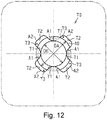
Fig. 12 shows a tapping screw being fastened with the prepared hole of the fourth embodiment; -
Fig. 13 shows a prepared hole of a fifth embodiment according to the present invention; and -
Fig. 14 shows a tapping screw being fastened with the prepared hole of the fifth embodiment. - With reference to
Figs. 1 to 6 , a description is given of a door leaf for a railroad vehicle of a first embodiment according to the present invention. The door leaf is used for a sliding door of a railroad vehicle. - As shown in
Fig. 1A , the left side of adoor leaf 10 is a trailing edge 11, and the right side of thedoor leaf 10 is aleading edge 12. In thedoor leaf 10, the trailing and leadingedges 11 and 12 have the same structure. As shown inFig. 1B , the longitudinal section of thedoor leaf 10 is curved at its vertically lower portion toward the inside of the railroad vehicle. - The
door leaf 10 includes aframe 20 andsurface plates 13 serving as panels or underlying boards and joined to the surfaces of theframe 20. Theframe 20 includesvertical frames 21 andhorizontal frames 22 connected to thevertical frames 21 orthogonally to the vertical frames 21. The vertical andhorizontal frames vertical frames 21 are a part of theframe 20 extending in the vertical direction of thedoor leaf 10. The horizontal frames 22 are a part of theframe 20 extending in the horizontal direction of thedoor leaf 10. Theframe 20 includes twovertical frames 21 and twohorizontal frames 22, which together form a quadrilateral frame. - As shown in
Fig. 2 , thesurface plates 13 are sticked using an adhesive onto the surfaces of theframe 20, which are shown on the lower and upper parts in the drawing. In other words, theframe 20 is sandwiched between the twosurface plates 13. - As shown in
Fig. 2 , thevertical frames 21 are extruded molded members shaped like a square cylinder and made of aluminum and made via extrusion molding. The horizontal frames 22 are extruded molded members shaped like a square rod and made of aluminum and made via extrusion molding. - The vertical and
horizontal frames screw 40. The tappingscrew 40 penetrates thevertical frame 21 and is screwed into aprepared hole 30 provided in thehorizontal frame 22 while tapping theprepared hole 30, so that the tappingscrew 40 fastens together the vertical andhorizontal frames vertical frame 21 has a first throughhole 21A, through which ascrew head 41 of the tappingscrew 40 can pass, and a second through hole 21B, through which a threadedportion 42 of the tappingscrew 40 can pass, formed therein. The second through hole 21B is sized such that thescrew head 41 of the tappingscrew 40 does not move through it. The entire portion of the tappingscrew 40 penetrates the first throughhole 21A, but only the threadedportion 42 penetrates the second through hole 21B. Thevertical frame 21 is sandwiched and fastened between thescrew head 41 of the tappingscrew 40 and thehorizontal frame 22. In other words, the vertical andhorizontal frames screw 40 andprepared hole 30. - As shown in
Fig. 3 , thehorizontal frame 22 is a member defining afirst space 22A, asecond space 22B, and athird space 22C. Thehorizontal frame 22 has, between thefirst space 22A and thesecond space 22B, theprepared hole 30, into which the tappingscrew 40 is to be screwed. As formed by extrusion molding, theprepared hole 30 entirely extends through thehorizontal frame 22. - As shown in
Fig. 4 , the tappingscrew 40 has thescrew head 41 and the threadedportion 42. Thescrew head 41 is of a truss type. The tappingscrew 40 is a type-B tapping screw with a coarse pitch, in which the threadedportion 42 has a blunt tip. The length of the threadedportion 42 is referred to as a screw length L. Since theprepared hole 30 extends through thehorizontal frame 22, the axial length of theprepared hole 30 is greater than the screw length L. The major diameter DA represents the diameter of the imaginary co-axial cylinder that touches the crests of the threadedportion 42, and the minor diameter DB represents the diameter of the imaginary co-axial cylinder that touches the roots of the threadedportion 42. - As shown in
Fig. 5 , in the plane orthogonal to the axial direction of the tappingscrew 40, the walls defining theprepared hole 30 in thehorizontal frame 22 are divided into a contact region A1 where the walls are to touch the tappingscrew 40 and a non-contact region A2 where the walls are not to touch the tappingscrew 40. The contact region A1 is, in the plane orthogonal to the axial direction of the tappingscrew 40, where the walls defining theprepared hole 30 are positioned inside the alternate long and two short dashes line representing the imaginary circle defining the major diameter DA of the tappingscrew 40. The non-contact region A2 is, in the plane orthogonal to the axial direction of the tappingscrew 40, where the walls defining theprepared hole 30 are positioned outside the alternate long and two short dashes line representing the imaginary circle defining the major diameter DA of the tappingscrew 40. Of the walls defining theprepared hole 30, the walls positioned in the contact region A1 are referred to as tapping-target walls 31, and the walls in the non-contact region A2 are referred to as non-tapping-target walls 32. Here, theprepared hole 30 extends along the entire length of thehorizontal frame 22. - The non-contact region A2 of the
prepared hole 30 preferably accounts for, in the plane orthogonal to the axial direction of the tappingscrew screw 40. In this case, the torque required for tightening the tappingscrew 40 is not too large, and therefore tapping can be performed satisfactorily. In addition, the portion to be tapped is not too small, and therefore a sufficient fastening force can be obtained. In the present embodiment, the non-contact region A2 accounts for approximately 50% of the circumference of the imaginary circle defining the major diameter DA of the tappingscrew 40. - Of the volume between the imaginary co-axial cylinders defining the major and minor diameters DA and DB of the tapping
screw 40, the not-to-be-tapped volume preferably accounts for 20% to 80%. In this case, the torque required for tightening the tappingscrew 40 is not too large, and therefore tapping can be performed satisfactorily. In addition, the portion to be tapped is not too small, and therefore a sufficient fastening force can be obtained. In the present embodiment, the not-to-be-tapped volume accounts for approximately 50%. - The walls defining the
prepared hole 30 are arranged in a point-symmetric manner and centered on the central axis of theprepared hole 30. In other words, the tapping-target walls 31 are point-symmetric, and so are the non-tapping-target walls 32. There are four tapping-target walls 31 and four non-tapping-target walls 32 alternating with each other. - The wall surface of the tapping-
target walls 31 in the contact region A1 has, in the plane orthogonal to the axial direction of the tappingscrew 40, a portion outside the imaginary circle defining the minor diameter DB of the tappingscrew 40 and centered on the center of theprepared hole 30. Here, the wall surface defines the boundary surface between theprepared hole 30 and thehorizontal frame 22. More specifically, in the plane orthogonal to the axial direction of the tappingscrew 40, the wall surface of the tapping-target walls 31 draws a straight line, the circumferentially middle point of the wall surface of the tapping-target walls 31 touches the imaginary circle defining the minor diameter DB, and the ends of the wall surface of the tapping-target walls 31 are close to the imaginary circle defining the major diameter DA. In other words, when the tappingscrew 40 is screwed into theprepared hole 30, the tightening torque is maximized at the middle portion of the tapping-target walls 31. As the tappingscrew 40 is increasingly screwed into theprepared hole 30, the contact area between the tappingscrew 40 and the tapping-target walls 31 gradually increases, which in turn increases the tightening torque. Accordingly, when compared with the case where the tappingscrew 40 evenly touches the tapping-target walls, the tightening torque can be reduced. - The non-tapping-
target walls 32 in the non-contact region A2 draw, in the plane orthogonal to the axial direction of the tappingscrew 40, a curved line parallel to the circumference of the imaginary circle defining the major diameter DA of the tappingscrew 40 and centered on the center of theprepared hole 30. - In the non-contact region A2, an
accommodating portion 33 is provided for accommodating the chips produced during the tapping by the tappingscrew 40. Theaccommodating portion 33 is positioned outside the imaginary circle defining the major diameter DA of the tappingscrew 40 and demarcated by the non-tapping-target walls 32 andside surfaces 31A of the tapping-target walls 31. - The following describes the method of manufacturing the
door leaf 10. - To begin with, as shown in
Fig. 2 , the second through hole 21B in thevertical frame 21 is aligned with theprepared hole 30 in thehorizontal frame 22, and thevertical frame 22 is brought into contact with thevertical frame 21. - Subsequently, the tapping
screw 40 is inserted through the first throughhole 21A and then through the second through hole 21B, and screwed in by being rotated with a tool. - As shown in
Fig. 6 , the tappingscrew 40 is screwed into theprepared hole 30 while tapping the contact region A1 of theprepared hole 30. In other words, the tapping-target walls 31 of theprepared hole 30, which are positioned between the imaginary circles representing the major and minor diameters DA and DB, are tapped. The dotted portions of the tapping-target walls 31 are tapped. In the upper right section of the drawing, when seen in the axial direction of the tappingscrew 40, the crests of the tappingscrew 40 are positioned above the tapping-target walls 31. Here, the non-contact region A2 of theprepared hole 30 does not touch the tappingscrew 40 and is thus not tapped. The chips produced by the tappingscrew 40 are accommodated in theaccommodating portion 33 of theprepared hole 30 or back in theprepared hole 30. - If a tapping-target wall extends along the entire circumference of the
prepared hole 30 and is positioned between the imaginary circles defining the major and minor diameters DA and DB, the tightening torque increases to such an extent that the tappingscrew 40 can no longer be tightened before the screwing is completed. To address this issue, the non-contact region A2 is provided in theprepared hole 30. This can reduce the to-be-tapped area in the plane orthogonal to the axial direction of the tappingscrew 40, thereby lowering the tightening torque. The tapping-target walls 31 are gradually removed such that the middle portion is first removed and the tapping width gradually increases. Accordingly, the tightening torque is maximized at the middle of the tapping-target wall 31. In this manner, less tightening torque can be produced on the tapping-target walls 31. - After this, as shown in
Fig. 2 , theframe 20, which is constituted by the twovertical frames 21 and the twohorizontal frames 22 fastened together, is sandwiched between the twosurface plates 13. An adhesive is applied onto the surfaces of theframe 20, and thesurface plates 13 are sticked onto the surfaces of theframe 20. Accordingly, thedoor leaf 10 can be readily manufactured without the use of welding on theframe 20. The fastening structure using the tappingscrew 40 is especially beneficial for thedoor leaf 10 having the curved lower portion since the welding may change the curving and thus require correction. - Advantageous effects of the first embodiment will be now described.
- (1) The
prepared hole 30 is not tapped along the entire circumference thereof but has the non-contact region A2 where the walls defining theprepared hole 30 do not touch the tappingscrew 40 and thus are not tapped. This can reduce the tightening torque produced when the tappingscrew 40 is tightened. Accordingly, the tappingscrew 40 can be used to fasten together the vertical andhorizontal frames vehicle door leaf 10 can be manufactured readily without the use of welding, which requires labor. - (2) Since the non-tapping-
target walls 32 defining theprepared hole 30 are positioned outside the imaginary circle defining the major diameter DA of the tappingscrew 40, they can serve as the non-contact region A2 where the walls do not touch the tappingscrew 40 when the tappingscrew 40 is tightened and thus are not tapped. - (3) The first embodiment can reduce the tightening torque produced by the tapping
screw 40 during the tapping, when compared with the case where the wall surface of the tapping-target walls 31 in the contact region A1 does not have a portion outside the imaginary circle defining the minor diameter DB of the tappingscrew 40, in other words, the contact region A1 is entirely inside the imaginary circle defining the minor diameter. - (4) When the tapping
screw 40 is tightened, the walls defining theprepared hole 30 abut the tappingscrew 40 at point-symmetric positions. Accordingly, the tappingscrew 40 can be positioned at the right position easily and thus stably tightened. - (5) The first embodiment can reduce the tightening torque produced when the tapping
screw 40 is tightened. Accordingly, the tappingscrew 40 can be used to fasten together the vertical andhorizontal frames - (6) Since the
accommodating portion 33 can accommodates therein the chips, the chips are prevented from coming between the tappingscrew 40 and the contact region A1. This can accordingly reduce the increase in tightening torque. - (7) Since extrusion molding is employed to make the
horizontal frames 22 with theprepared hole 30, even theprepared hole 30 having the complex shape can be successfully shaped. The extrusion molding eliminates the need of separately shaping theprepared hole 30. - With reference to
Figs. 7 and8 , a description is given of a door leaf for a railroad vehicle of a second embodiment according to the present invention. The second embodiment is different from the first embodiment in terms of the shape of the prepared hole. The following description will be focused on the differences from the first embodiment. - As shown in
Figs. 7 and8 , thehorizontal frame 22 has aprepared hole 50 formed therein, into which the tappingscrew 40 is to be screwed. In the plane orthogonal to the axial direction of the tappingscrew 40, the walls defining theprepared hole 50 are divided into a contact region A1 where the walls are tapped by the tappingscrew 40 and a non-contact region A2 where the walls do not touch the tappingscrew 40 and are thus not tapped. The contact region A1 is, in the plane orthogonal to the axial direction of the tappingscrew 40, where the walls defining theprepared hole 50 are positioned inside the alternate long and two short dashes line representing the imaginary circle defining the major diameter DA of the tappingscrew 40. The non-contact region A2 is, in the plane orthogonal to the axial direction of the tappingscrew 40, where the walls defining theprepared hole 50 are positioned outside the alternate long and two short dashes line representing the imaginary circle defining the major diameter DA of the tappingscrew 40. Of the walls defining theprepared hole 50, the walls positioned in the contact region A1 are referred to as tapping-target walls 51, and the walls positioned in the non-contact region A2 are referred to as non-tapping-target walls 52. - The non-contact region A2 accounts for, in the plane orthogonal to the axial direction of the tapping
screw 40, approximately 30% of the circumference of the imaginary circle defining the major diameter DA of the tappingscrew 40. Of the volume between the imaginary co-axial cylinders defining the major and minor diameters DA and DB of the tappingscrew 40, the not-to-be-tapped volume accounts for approximately 30%. - The walls defining the
prepared hole 50 are arranged in a point-symmetric manner and centered on the central axis of theprepared hole 50. In other words, the tapping-target walls 51 are point-symmetric, and so are the non-tapping-target walls 52. There are four tapping-target walls 51 and four non-tapping-target walls 52 alternating with each other. - The tapping-
target walls 51 in the contact region A1 are, in the plane orthogonal to the axial direction of the tappingscrew 40, parallel to the circumference of the imaginary circle defining the major diameter DA of the tappingscrew 40 and centered on the center of theprepared hole 50. More specifically, the tapping-target walls 51 draw, in the plane orthogonal to the axial direction of the tappingscrew 40, a curved line and overlap the imaginary circle defining the minor diameter DB. In other words, when the tappingscrew 40 is screwed into theprepared hole 50, the same tightening torque is produced at any position on the tapping-target walls 51. As shown inFig. 8 , the dotted portion of the tapping-target walls 51 are tapped and engaged with the tappingscrew 40. In the upper right section of the drawing, when seen in the axial direction of the tappingscrew 40, the crests of the tappingscrew 40 are positioned above the tapping-target walls 51. - The non-tapping-
target walls 52 in the non-contact region A2 draw, in the plane orthogonal to the axial direction of the tappingscrew 40, a curved line parallel to the circumference of the imaginary circle defining the major diameter DA of the tappingscrew 40 and centered on the center of theprepared hole 50. - In the non-contact region A2, an
accommodating portion 53 is provided for accommodating the chips produced during the tapping by the tappingscrew 40. Theaccommodating portion 53 is positioned outside the imaginary circle defining the major diameter DA of the tappingscrew 40 and demarcated by the non-tapping-target walls 52 andside surfaces 51A of the tapping-target walls 51. - As described above, the non-contact region A2 is provided in the
prepared hole 50. This can reduce the to-be-tapped area in the plane orthogonal to the axial direction of the tappingscrew 40, thereby lowering the tightening torque. On the tapping-target walls 51, the tapping width remains constant. Accordingly, the tightening torque remains unchanged on the tapping-target walls 51. In this manner, the tightening torque can be stabilized. - Advantageous effects of the second embodiment will be now described. The following advantageous effects are obtained in addition to the advantageous effects (1), (2), and (4) to (7) of the first embodiment.
- (8) The distance between the contact region A1 and the tapping
screw 40 is constant. Accordingly, the tappingscrew 40 can be positioned at the right position easily and thus stably tightened. - With reference to
Figs. 9 and10 , a description is given of a door leaf for a railroad vehicle of a third embodiment according to the present invention. The third embodiment is different from the first embodiment in terms of the shape of the prepared hole. The following description will be focused on the differences from the first embodiment. - As shown in
Figs. 9 and10 , thehorizontal frame 22 has aprepared hole 60 formed therein, into which the tappingscrew 40 is to be screwed. In the plane orthogonal to the axial direction of the tappingscrew 40, the walls defining theprepared hole 60 are divided into a contact region A1 where the walls are tapped by the tappingscrew 40 and a non-contact region A2 where the walls do not touch the tappingscrew 40 and are thus not tapped. The contact region A1 is, in the plane orthogonal to the axial direction of the tappingscrew 40, where the walls defining theprepared hole 60 are positioned inside the alternate long and two short dashes line representing the imaginary circle defining the major diameter DA of the tappingscrew 40. The non-contact region A2 is, in the plane orthogonal to the axial direction of the tappingscrew 40, where the walls defining theprepared hole 60 are positioned outside the alternate long and two short dashes line representing the imaginary circle defining the major diameter DA of the tappingscrew 40. Of the walls defining theprepared hole 60, the walls positioned in the contact region A1 are referred to as tapping-target walls 61, and the walls positioned in the non-contact region A2 are referred to as non-tapping-target walls 62. - The non-contact region A2 accounts for, in the plane orthogonal to the axial direction of the tapping
screw 40, approximately 50% of the circumference of the imaginary circle defining the major diameter DA of the tappingscrew 40. Of the volume between the imaginary co-axial cylinders defining the major and minor diameters DA and DB of the tappingscrew 40, the not-to-be-tapped volume accounts for approximately 50%. - The walls defining the
prepared hole 60 are arranged in a point-symmetric manner and centered on the central axis of theprepared hole 60. In other words, the tapping-target walls 61 are point-symmetric, and so are the non-tapping-target walls 62. There are four tapping-target walls 61 and four non-tapping-target walls 62 alternating with each other. - The tapping-
target walls 61 in the contact region A1 are, in the plane orthogonal to the axial direction of the tappingscrew 40, parallel to the circumference of the imaginary circle defining the major diameter DA of the tappingscrew 40 and centered on the center of theprepared hole 60. More specifically, the tapping-target walls 61 draw, in the plane orthogonal to the axial direction of the tappingscrew 40, a curved line and overlap the imaginary circle defining the minor diameter DB. In other words, when the tappingscrew 40 is screwed into theprepared hole 60, the same tightening torque is produced at any position on the tapping-target walls 61. As shown inFig. 10 , the dotted portion of the tapping-target walls 61 are tapped and engaged with the tappingscrew 40. In the upper right section of the drawing, when seen in the axial direction of the tappingscrew 40, the crests of the tappingscrew 40 are positioned above the tapping-target walls 61. - The non-tapping-
target walls 62 in the non-contact region A2 draw, in the plane orthogonal to the axial direction of the tappingscrew 40, an arc of a circle centered on a point different from the screw axis of the tappingscrew 40. - In the non-contact region A2, an
accommodating portion 63 is provided for accommodating the chips produced during the tapping by the tappingscrew 40. Theaccommodating portion 63 is positioned outside the imaginary circle defining the major diameter DA of the tappingscrew 40 and demarcated by the non-tapping-target walls 62. - As described above, the non-contact region A2 is provided in the
prepared hole 60. This can reduce the to-be-tapped area in the plane orthogonal to the axial direction of the tappingscrew 40, thereby lowering the tightening torque. On the tapping-target walls 61, the tapping width remains constant. Accordingly, the tightening torque remains unchanged on the tapping-target walls 61. In this manner, the tightening torque can be stabilized. According to the third embodiment, the advantageous effects (1), (2), and (4) to (7) of the first embodiment and (8) of the second embodiment are obtained. - With reference to
Figs. 11 and12 , a description is given of a door leaf for a railroad vehicle of a fourth embodiment according to the present invention. The fourth embodiment is different from the first embodiment in terms of the shape of the prepared hole. The following description will be focused on the differences from the first embodiment. - As shown in
Figs. 11 and12 , thehorizontal frame 22 has aprepared hole 70 formed therein, into which the tappingscrew 40 is to be screwed. In the plane orthogonal to the axial direction of the tappingscrew 40, the walls defining theprepared hole 70 are divided into a contact region A1 where the walls are tapped by the tappingscrew 40 and a non-contact region A2 where the walls do not touch the tappingscrew 40 and are thus not tapped. The contact region A1 is, in the plane orthogonal to the axial direction of the tappingscrew 40, where the walls defining theprepared hole 70 are positioned inside the alternate long and two short dashes line representing the imaginary circle defining the major diameter DA of the tappingscrew 40. The non-contact region A2 is, in the plane orthogonal to the axial direction of the tappingscrew 40, where the walls defining theprepared hole 70 are positioned outside the alternate long and two short dashes line representing the imaginary circle defining the major diameter DA of the tappingscrew 40. Of the walls defining theprepared hole 70, the walls positioned in the contact region A1 are referred to as tapping-target walls 71, and the walls positioned in the non-contact region A2 are referred to as non-tapping-target walls 72. - The non-contact region A2 accounts for, in the plane orthogonal to the axial direction of the tapping
screw 40, approximately 60% of the circumference of the imaginary circle defining the major diameter DA of the tappingscrew 40. Of the volume between the imaginary co-axial cylinders defining the major and minor diameters DA and DB of the tappingscrew 40, the not-to-be-tapped volume accounts for approximately 60%. - The walls defining the
prepared hole 70 are arranged in a point-symmetric manner and centered on the central axis of theprepared hole 70. In other words, the tapping-target walls 71 are point-symmetric, and so are the non-tapping-target walls 72. There are four tapping-target walls 71 and four non-tapping-target walls 72 alternating with each other. - The wall surface of the tapping-
target walls 71 in the contact region A1 has, in the plane orthogonal to the axial direction of the tappingscrew 40, a portion outside the imaginary circle defining the minor diameter DB of the tappingscrew 40 and centered on the center of theprepared hole 70. Here, the wall surface defines the boundary surface between theprepared hole 70 and thehorizontal frame 22. More specifically, in the plane orthogonal to the axial direction of the tappingscrew 40, the wall surface of the tapping-target walls 71 draws a curved line, the circumferentially middle point of the wall surface of the tapping-target walls 71 touches the imaginary circle defining the minor diameter DB, and the ends of the wall surface of the tapping-target walls 71 are close to the imaginary circle defining the major diameter DA. In other words, when the tappingscrew 40 is screwed into theprepared hole 70, the tightening torque is maximized at the middle portion of the tapping-target walls 71. As the tappingscrew 40 is increasingly screwed into theprepared hole 70, the contact area between the tappingscrew 40 and the tapping-target walls 71 gradually increases, which increases the tightening torque. As shown inFig. 12 , the dotted portion of the tapping-target walls 71 are tapped and engaged with the tappingscrew 40. In the upper right section of the drawing, when seen in the axial direction of the tappingscrew 40, the crests of the tappingscrew 40 are positioned above the tapping-target walls 71. Accordingly, when compared with the second and third embodiments where the tappingscrew 40 evenly touches the tapping-target walls - The non-tapping-
target wall 72 in the non-contact region A2 have, in the plane orthogonal to the axial direction of the tappingscrew 40, a portion outside the imaginary circle defining the major diameter DA of the tappingscrew 40. More specifically, the non-tapping-target walls 72 draw, in the plane orthogonal to the axial direction of the tappingscrew 40, a straight line and curved lines connecting with the tapping-target walls 71. - In the non-contact region A2, an
accommodating portion 73 is provided for accommodating the chips produced during the tapping by the tappingscrew 40. Theaccommodating portion 73 is positioned outside the imaginary circle defining the major diameter DA of the tappingscrew 40 and demarcated by the non-tapping-target walls 72. - As described above, the non-contact region A2 is provided in the
prepared hole 70. This can reduce the to-be-tapped area in the plane orthogonal to the axial direction of the tappingscrew 40, thereby lowering the tightening torque. The tapping-target walls 71 are gradually removed such that the middle portion is first removed and the tapping width gradually increases. Accordingly, the tightening torque is maximized at the middle of the tapping-target walls 71. In this manner, less tightening torque can be produced at the tapping-target walls 71. According to the fourth embodiment, the advantageous effects (1) to (7) of the first embodiment are obtained. - With reference to
Figs. 13 and14 , a description is given of a door leaf for a railroad vehicle of a fifth embodiment according to the present invention. The fifth embodiment is different from the first embodiment in terms of the shape of the prepared hole. The following description will be focused on the differences from the first embodiment. - As shown in
Figs. 13 and14 , thehorizontal frame 22 has aprepared hole 80 formed therein, into which the tappingscrew 40 is to be screwed. In the plane orthogonal to the axial direction of the tappingscrew 40, the walls defining theprepared hole 80 are divided into a contact region A1 where the walls are tapped by the tappingscrew 40 and a non-contact region A2 where the walls do not touch the tappingscrew 40 and are thus not tapped. The contact region A1 is, in the plane orthogonal to the axial direction of the tappingscrew 40, where the walls defining theprepared hole 80 are positioned inside the alternate long and two short dashes line representing the imaginary circle defining the major diameter DA of the tappingscrew 40. The non-contact region A2 is, in the plane orthogonal to the axial direction of the tappingscrew 40, where the walls defining theprepared hole 80 are positioned outside the alternate long and two short dashes line representing the imaginary circle defining the major diameter DA of the tappingscrew 40. Of the walls defining theprepared hole 80, the walls positioned in the contact region A1 are referred to as tapping-target walls 81, and the walls positioned in the non-contact region A2 are referred to as non-tapping-target walls 82. - The non-contact region A2 accounts for, in the plane orthogonal to the axial direction of the tapping
screw 40, approximately 60% of the circumference of the imaginary circle defining the major diameter DA of the tappingscrew 40. Of the volume between the imaginary co-axial cylinders defining the major and minor diameters DA and DB of the tappingscrew 40, the not-to-be-tapped volume accounts for approximately 60%. - The walls defining the
prepared hole 80 are arranged in a point-symmetric manner and centered on the central axis of theprepared hole 80. In other words, the tapping-target walls 81 are point-symmetric, and so are the non-tapping-target walls 82. There are four tapping-target walls 81 and four non-tapping-target walls 82 alternating with each other. - The wall surface of the tapping-
target walls 81 in the contact region A1 has, in the plane orthogonal to the axial direction of the tappingscrew 40, a portion outside the imaginary circle defining the minor diameter DB of the tappingscrew 40 and centered on the center of theprepared hole 80. Here, the wall surface defines the boundary surface between theprepared hole 80 and thehorizontal frame 22. More specifically, in the plane orthogonal to the axial direction of the tappingscrew 40, the tapping-target walls 81 draw a straight line, the middle of the tapping-target walls 81 touch the imaginary circle defining the minor diameter DB, and the ends of the tapping-target walls 81 are close to the imaginary circle defining the major diameter DA. In other words, when the tappingscrew 40 is screwed into theprepared hole 80, the tightening torque is maximized at the middle portion of the tapping-target walls 81. As the tappingscrew 40 is increasingly screwed into theprepared hole 80, the contact area between the tappingscrew 40 and the tapping-target walls 81 gradually increases, which increases the tightening torque. As shown inFig. 14 , the dotted portion of the tapping-target walls 81 are tapped and engaged with the tappingscrew 40. In the upper right section of the drawing, when seen in the axial direction of the tappingscrew 40, the crests of the tappingscrew 40 are positioned above the tapping-target walls 81. Accordingly, when compared with the second and third embodiments where the tappingscrew 40 evenly touches the tapping-target walls - The non-tapping-
target walls 82 in the non-contact region A2 have, in the plane orthogonal to the axial direction of the tappingscrew 40, a portion outside the imaginary circle defining the major diameter DA of the tappingscrew 40. More specifically, the non-tapping-target walls 82 draw, in the plane orthogonal to the axial direction of the tappingscrew 40, a straight line continuous from the tapping-target walls 81 and curved lines connecting with two such straight lines. - In the non-contact region A2, an
accommodating portion 83 is provided for accommodating the chips produced during the tapping by the tappingscrew 40. Theaccommodating portion 73 is positioned outside the imaginary circle defining the major diameter DA of the tappingscrew 40 and demarcated by the non-tapping-target walls 82. - As described above, the non-contact region A2 is provided in the
prepared hole 80. This can reduce the to-be-tapped area in the plane orthogonal to the axial direction of the tappingscrew 40, thereby lowering the tightening torque. The tapping-target walls 81 are gradually removed such that the middle portion is first removed and the tapping width gradually increases. Accordingly, the tightening torque is maximized at the middle of the tapping-target walls 81. In this manner, less tightening torque can be produced at the tapping-target walls 81. - Advantageous effects of the fifth embodiment will be now described. The following advantageous effects are obtained in addition to the advantageous effects (1) to (7) of the first embodiment.
- (9) Since the tapping-target and non-tapping-
target walls prepared hole 80 draw successive straight lines, theprepared hole 80 does not have a complex shape and thehorizontal frames 22 can be extrusion-molded more easily than those with a prepared hole having a complex shape formed therein. - The foregoing embodiments can be modified as described below. The above embodiments and the following modifications can be implemented in combination to the extent where they are technically consistent with each other.
- In the above-described embodiments, the
prepared holes horizontal frame 22. The prepared holes may, however, have different shapes at different horizontal positions along the length of thehorizontal frame 22. In the axial direction of the tappingscrew 40, a first position close to thescrew head 41 and a second position close to the tip are defined. The walls defining the prepared holes are, in the plane orthogonal to the axial direction of the tappingscrew 40 at the first position, divided into a first contact region where the walls touch the tappingscrew 40 and a first non-contact region where the walls do not touch the tappingscrew 40. The walls defining the prepared holes are, in the plane orthogonal to the axial direction of the tappingscrew 40 at the second position, which is closer in the axial direction of the tappingscrew 40 to the tip of the tappingscrew 40 than the first position is, divided into a second contact region where the walls touch the tappingscrew 40 and a second non-contact region where the walls do not touch the tappingscrew 40. Here, the ratio of the first non-contact region to the sum of the first contact and non-contact regions may be higher than the ratio of the second non-contact region to the sum of the second contact and non-contact regions. For example, theprepared hole 30 of the first embodiment having a ratio of 50% may be formed at the first position closer to thescrew head 41, and theprepared hole 50 of the second embodiment having a ratio of 30% may be formed at the second position closer to the tip. Alternatively, this design may be accomplished by forming a prepared hole extending off the axial direction of the tappingscrew 40. In either way, the tightening torque can be weak on thescrew head 41 side and the tightening strength can be high at the tip side. - Alternatively, the non-contact region A2 may be provided only in a partial region in the axial direction of the tapping
screw 40. For example, the above design may be implemented by forming theprepared holes screw 40. - In the above-described embodiments, the non-contact region A2 is, in the plane orthogonal to the axial direction of the tapping
screw 40, where the walls defining theprepared holes screw 40. Alternatively, the non-contact region A2 may be, however, in the plane orthogonal to the axial direction of the tappingscrew 40, where the wall defining theprepared holes screw 40. In this case, no accommodating portions are provided. - In the above-described embodiments, the walls defining the
prepared holes prepared holes - In the above-described embodiments, the
prepared holes horizontal frames 22 but may be alternatively formed in thehorizontal frames 22 via cutting or other techniques. - The length of the prepared holes may be less than the entire length of the
horizontal frames 22 as long as it is equal to or longer than the screw length L of the tapping screw when measured from the opening. - In the above-described embodiments, the first, second, and
third spaces horizontal frames 22, but any or no spaces may be provided in the horizontal frames 22. - In the above-described embodiments, the tapping
screw 40 is a type-B tapping screw but is not limited to such and may be a type-A tapping screw, having a drilling point, threaded to the tip end, and having a more coarse thread pitch than a type-B tapping screw, a type-C tapping screw, having a blunt point and a finer thread pitch than a type-B tapping screw, or a type-AB tapping screw, having a drilling point, threaded to the tip end, and having the same thread pitch as a type-B tapping screw. Alternatively, a thread cutting screw having a cutting edge at the tip thereof may be used. As a further another example, a tapping screw having a threaded portion with a triangular cross-section may be used. - In the above-described embodiments, the
screw head 41 of the tappingscrew 40 is a truss head, but can be of other types such as flat head, raised countersunk head, and pan head. - In the above-described embodiments, the size of the prepared holes may be changed depending on the major and minor diameters DA and DB of the tapping
screw 40. - In the above-described embodiments, the
prepared holes horizontal frames 22, which are referred to as the second member, and the second through hole 21B is provided in thevertical frames 21, which are referred to as the first member. However, the through hole may be provided in the horizontal frames, which are referred to as the first member, and the prepared hole may be provided in the vertical frames, which are referred to as the second member. In this case, the horizontal frames may be fastened onto the vertical frames with the tapping screws. - In the above-described embodiments, the vertically lower portion of the
door leaf 10 is curved toward the inside of the railroad vehicle, but may not be curved and instead draw a straight line. - In the above-described embodiments, the fastening structure in the
frame 20 of the railroadvehicle door leaf 10 includes the tapping screw and the prepared hole, which may be used as a fastening structure constituted by two members in other structures than the frame of a railroad vehicle door leaf. - In the above-described embodiments, the two members are fastened together not using welding but using the tapping screw and the prepared hole. If the two members are subjected to welding after being fastened together using the tapping screw and the prepare hole, however, this may reduce the distortion that can result from the welding and eliminate the need of the correction to satisfy the required precision.
Claims (15)
- A door leaf (10) for a railroad vehicle, the door leaf (10) including a first member (21) and a second member (22), the door leaf (10) comprising
a tapping screw (40) to be screwed into a prepared hole (30) provided in the second member (22) while tapping the prepared hole (30), so that the tapping screw (40) fastens together the first and second members (21, 22),
wherein walls defining the prepared hole (30) in the second member (22) have, in a plane orthogonal to an axial direction of the tapping screw (40), a non-contact region (A2) where the walls do not touch the tapping screw (40). - The door leaf (10) for a railroad vehicle of claim 1, wherein, in the plane orthogonal to the axial direction of the tapping screw (40), the non-contact region (A2) is positioned outside an imaginary circle defining a major diameter (DA) of the tapping screw (40).
- The door leaf (10) for a railroad vehicle of claim 1 or 2,
wherein the walls defining the prepared hole (30) have, in the plane orthogonal to the axial direction of the tapping screw (40), a contact region (A1) where the walls touch the tapping screw (40), and
wherein, of the walls in the contact region (A1), one or more walls extending in a circumferential direction of the tapping screw (40) are, in the plane orthogonal to the axial direction of the tapping screw (40), parallel to a circumference of an imaginary circle defining a major diameter (DA) of the tapping screw (40) and centered on a center of the prepared hole (30). - The door leaf (10) for a railroad vehicle of claim 1 or 2,
wherein the walls defining the prepared hole (30) have, in the plane orthogonal to the axial direction of the tapping screw (40), a contact region (A1) where the walls touch the tapping screw (40), and
wherein a wall surface in the contact region (A1) has, in the plane orthogonal to the axial direction of the tapping screw (40), a portion outside an imaginary circle defining a minor diameter (DB) of the tapping screw (40) and centered on a center of the prepared hole (30). - The door leaf (10) for a railroad vehicle of any one of claims 1 to 4, wherein the walls defining the prepared hole (30) are arranged in a point-symmetric manner and centered on a central axis of the prepared hole (30).
- The door leaf (10) for a railroad vehicle of any one of claims 1 to 5, wherein the non-contact region (A2) accounts for, in the plane orthogonal to the axial direction of the tapping screw (40), 20% to 80% of a circumference of an imaginary circle defining a major diameter (DA) of the tapping screw (40).
- The door leaf (10) for a railroad vehicle of any one of claims 1 to 5, wherein, of a volume between imaginary co-axial cylinders defining major and minor diameters (DA, DB) of the tapping screw (40), a not-to-be-tapped volume accounts for 20% to 80%.
- The door leaf (10) for a railroad vehicle of any one of claims 1 to 5,
wherein the walls defining the prepared hole (30) are divided into:in a plane orthogonal to the axial direction of the tapping screw (40) at a first position, a first contact region where the walls touch the tapping screw (40) and a first non-contact region where the walls do not touch the tapping screw (40); andin a plane orthogonal to the axial direction of the tapping screw (40) at a second position, the second position being closer in the axial direction of the tapping screw (40) to a tip of the tapping screw (40) than the first position is, a second contact region where the walls touch the tapping screw (40) and a second non-contact region where the walls do not touch the tapping screw (40), andwherein the ratio of the first non-contact region to the sum of the first contact and non-contact regions is higher than the ratio of the second non-contact region to the sum of the second contact and non-contact regions. - The door leaf (10) for a railroad vehicle of any one of claims 1 to 5, wherein the non-contact region (A2) is provided in a partial region in the axial direction of the tapping screw (40).
- The door leaf (10) for a railroad vehicle of any one of claims 1 to 9, wherein, in the non-contact region (A2), an accommodating portion is further provided for accommodating chips produced during tapping by the tapping screw (40).
- The door leaf (10) for a railroad vehicle of any one of claims 1 to 10, wherein the second member (22) having the prepared hole (30) provided therein is extrusion-molded.
- The door leaf (10) for a railroad vehicle of any one of claims 1 to 11, wherein the door leaf (10) includes a frame made up by vertical and horizontal frames (21, 22), one of the first and second members (21, 22) is the vertical frame (21) and the other of the first and second members (21, 22) is the horizontal frame (22).
- The door leaf (10) for a railroad vehicle of claim 12, wherein the first member (21) is the vertical frame (21) and the second member (22) is the horizontal frame (22).
- A fastening structure for fastening together a first member (21) and a second member (22), the fastening structure comprising
a tapping screw (40) to be screwed into a prepared hole (30) provided in the second member (22) while tapping the prepared hole (30), so that the tapping screw (40) fastens together the first and second members (21, 22),
wherein walls defining the prepared hole (30) in the second member (22) have, in a plane orthogonal to an axial direction of the tapping screw (40), a non-contact region (A2) where the walls do not touch the tapping screw (40). - A method of manufacturing a door leaf (10) for a railroad vehicle, wherein
the door leaf (10) includes a first member (21) and a second member (22),
the second member (22) is provided with a prepared hole (30) into which a tapping screw (40) is to be screwed, and
walls defining the prepared hole (30) have, in a plane orthogonal to an axial direction of the tapping screw (40), a non-contact region (A2) where the walls do not touch the tapping screw (40), the method comprising
fastening together the first and second members (21, 22) by screwing the tapping screw (40) into the prepared hole (30) in the second member (22) while the tapping screw (40) is tapping the prepared hole (30).
Applications Claiming Priority (1)
| Application Number | Priority Date | Filing Date | Title |
|---|---|---|---|
| JP2020086332A JP7488105B2 (en) | 2020-05-15 | 2020-05-15 | Door leaf for railway vehicle, fastening structure, and method for manufacturing door leaf for railway vehicle |
Publications (2)
| Publication Number | Publication Date |
|---|---|
| EP3909827A1 true EP3909827A1 (en) | 2021-11-17 |
| EP3909827B1 EP3909827B1 (en) | 2023-03-22 |
Family
ID=75441782
Family Applications (1)
| Application Number | Title | Priority Date | Filing Date |
|---|---|---|---|
| EP21167620.0A Active EP3909827B1 (en) | 2020-05-15 | 2021-04-09 | Door leaf for railroad vehicle, fastening structure, and method of manufacturing door leaf for railroad vehicle |
Country Status (3)
| Country | Link |
|---|---|
| EP (1) | EP3909827B1 (en) |
| JP (1) | JP7488105B2 (en) |
| CN (1) | CN113665609A (en) |
Cited By (1)
| Publication number | Priority date | Publication date | Assignee | Title |
|---|---|---|---|---|
| EP4406807A1 (en) * | 2022-12-05 | 2024-07-31 | Knorr-Bremse Gesellschaft mit beschränkter Haftung | Door leaf for a rail vehicle and method for producing a door leaf |
Families Citing this family (1)
| Publication number | Priority date | Publication date | Assignee | Title |
|---|---|---|---|---|
| JP7830014B2 (en) * | 2023-11-01 | 2026-03-16 | 矢崎総業株式会社 | terminal block |
Citations (9)
| Publication number | Priority date | Publication date | Assignee | Title |
|---|---|---|---|---|
| JPH0457481A (en) | 1990-06-27 | 1992-02-25 | Hitachi Ltd | video camera equipment |
| US5294225A (en) * | 1991-11-21 | 1994-03-15 | K.K. Aoyama Seisakusho | Synthetic resin grommet |
| DE9408079U1 (en) * | 1994-05-17 | 1994-07-14 | Gebr. Bode & Co GmbH, 34123 Kassel | Vehicle door for public transport, in particular buses and rail vehicles |
| DE29708272U1 (en) * | 1997-05-07 | 1997-07-03 | Reiche GmbH & Co. KG Ausstattungen für Schienenfahrzeuge, 32791 Lage | Single or double-leaf sliding door for a railroad car |
| JPH1162939A (en) * | 1997-08-21 | 1999-03-05 | Sugiura Seisakusho:Kk | Female screw member |
| KR20040081981A (en) * | 2003-03-17 | 2004-09-23 | 김종순 | Doorchassis assembly structure that use screwbolt |
| FR2861818A1 (en) * | 2003-11-04 | 2005-05-06 | Piolax Inc | Sleeve for screw, has projection that is inclined towards base in direction in which screwing unit is screwed, and projection that maintains pressure contact with internal periphery surface of assembling hole of vehicle panel |
| DE102012107422A1 (en) * | 2012-08-13 | 2014-02-13 | Knorr-Bremse Gmbh | Door leaf for a vehicle, in particular a rail vehicle |
| CN207955649U (en) * | 2018-03-02 | 2018-10-12 | 江苏丰顺新材料科技有限公司 | The door and doorframe mounting structure of rail traffic |
Family Cites Families (9)
| Publication number | Priority date | Publication date | Assignee | Title |
|---|---|---|---|---|
| JPS59160163U (en) * | 1983-04-13 | 1984-10-26 | 山水電気株式会社 | screw tightening device |
| JPS63173769U (en) * | 1987-04-30 | 1988-11-11 | ||
| JP2000283119A (en) * | 1999-03-29 | 2000-10-13 | Tokyo Gas Co Ltd | Screw structure and members |
| JP2002181024A (en) * | 2000-12-15 | 2002-06-26 | Nec Corp | Screwing structure |
| JP2004044644A (en) * | 2002-07-10 | 2004-02-12 | Nippon Pop Rivets & Fasteners Ltd | Screw grommet |
| JP4244316B2 (en) * | 2003-11-28 | 2009-03-25 | 株式会社リコー | Fastening structure, fastening method, and image forming apparatus |
| JP6069731B2 (en) * | 2013-04-23 | 2017-02-01 | ポップリベット・ファスナー株式会社 | Location pin mounting structure |
| JP5932741B2 (en) * | 2013-09-10 | 2016-06-08 | アルナ輸送機用品株式会社 | Manufacturing method of door for vehicle |
| JP6209178B2 (en) * | 2015-03-30 | 2017-10-04 | 大建工業株式会社 | Nut member and frame material coupling structure using the same |
-
2020
- 2020-05-15 JP JP2020086332A patent/JP7488105B2/en active Active
-
2021
- 2021-04-09 EP EP21167620.0A patent/EP3909827B1/en active Active
- 2021-04-15 CN CN202110403532.XA patent/CN113665609A/en active Pending
Patent Citations (9)
| Publication number | Priority date | Publication date | Assignee | Title |
|---|---|---|---|---|
| JPH0457481A (en) | 1990-06-27 | 1992-02-25 | Hitachi Ltd | video camera equipment |
| US5294225A (en) * | 1991-11-21 | 1994-03-15 | K.K. Aoyama Seisakusho | Synthetic resin grommet |
| DE9408079U1 (en) * | 1994-05-17 | 1994-07-14 | Gebr. Bode & Co GmbH, 34123 Kassel | Vehicle door for public transport, in particular buses and rail vehicles |
| DE29708272U1 (en) * | 1997-05-07 | 1997-07-03 | Reiche GmbH & Co. KG Ausstattungen für Schienenfahrzeuge, 32791 Lage | Single or double-leaf sliding door for a railroad car |
| JPH1162939A (en) * | 1997-08-21 | 1999-03-05 | Sugiura Seisakusho:Kk | Female screw member |
| KR20040081981A (en) * | 2003-03-17 | 2004-09-23 | 김종순 | Doorchassis assembly structure that use screwbolt |
| FR2861818A1 (en) * | 2003-11-04 | 2005-05-06 | Piolax Inc | Sleeve for screw, has projection that is inclined towards base in direction in which screwing unit is screwed, and projection that maintains pressure contact with internal periphery surface of assembling hole of vehicle panel |
| DE102012107422A1 (en) * | 2012-08-13 | 2014-02-13 | Knorr-Bremse Gmbh | Door leaf for a vehicle, in particular a rail vehicle |
| CN207955649U (en) * | 2018-03-02 | 2018-10-12 | 江苏丰顺新材料科技有限公司 | The door and doorframe mounting structure of rail traffic |
Cited By (1)
| Publication number | Priority date | Publication date | Assignee | Title |
|---|---|---|---|---|
| EP4406807A1 (en) * | 2022-12-05 | 2024-07-31 | Knorr-Bremse Gesellschaft mit beschränkter Haftung | Door leaf for a rail vehicle and method for producing a door leaf |
Also Published As
| Publication number | Publication date |
|---|---|
| JP7488105B2 (en) | 2024-05-21 |
| JP2021178616A (en) | 2021-11-18 |
| EP3909827B1 (en) | 2023-03-22 |
| CN113665609A (en) | 2021-11-19 |
Similar Documents
| Publication | Publication Date | Title |
|---|---|---|
| EP3909827B1 (en) | Door leaf for railroad vehicle, fastening structure, and method of manufacturing door leaf for railroad vehicle | |
| US20100260573A1 (en) | Utility strap | |
| EP3056747B1 (en) | Mounting screw | |
| CN1138892A (en) | Self-drilling and thread-forming bits with flow-formed sections | |
| US20200038968A1 (en) | Conical countersink | |
| US11703074B2 (en) | Thread-forming or self-tapping screw, in particular for use in light metal | |
| US11820037B2 (en) | Punch and draw stud having multi-start threads, and method of engaging same | |
| KR102040304B1 (en) | Connecting block allowing parallel movement between profiles without perforation | |
| CN102052377A (en) | Bolt for panel combination and panel combination method using the same | |
| SE453772B (en) | DRILLING SCREW | |
| US20260108062A1 (en) | Assembly composed of a furniture fitting and a furniture carcass and/or a movable furniture part | |
| CN1254401A (en) | Screw | |
| US5842923A (en) | Screw and method for its production | |
| US3168171A (en) | Laminated sheet metal nut | |
| CN2478754Y (en) | Binding elements for wood panels | |
| CA2793494C (en) | Self-tapping screw | |
| WO2018138407A1 (en) | Fastening element and arrangement in a frame structure of a vehicle | |
| US10125806B2 (en) | Slotted set screw structure | |
| US8807511B2 (en) | Fastening system for add-on parts on a vehicle having a profile-like connection part | |
| CN207773265U (en) | Rear panel and vehicle with same | |
| CN218017154U (en) | Frock is fixed in car shell sub-assembly bore hole | |
| CN201575026U (en) | Self-tapping screw thread insert for operating loupe | |
| CN104533916A (en) | Self-tapping screw with sawtooth threads | |
| CN208381057U (en) | A kind of compoboard | |
| CN219787470U (en) | Device for adjustable mounting fixture |
Legal Events
| Date | Code | Title | Description |
|---|---|---|---|
| PUAI | Public reference made under article 153(3) epc to a published international application that has entered the european phase |
Free format text: ORIGINAL CODE: 0009012 |
|
| STAA | Information on the status of an ep patent application or granted ep patent |
Free format text: STATUS: REQUEST FOR EXAMINATION WAS MADE |
|
| 17P | Request for examination filed |
Effective date: 20210409 |
|
| AK | Designated contracting states |
Kind code of ref document: A1 Designated state(s): AL AT BE BG CH CY CZ DE DK EE ES FI FR GB GR HR HU IE IS IT LI LT LU LV MC MK MT NL NO PL PT RO RS SE SI SK SM TR |
|
| B565 | Issuance of search results under rule 164(2) epc |
Effective date: 20211001 |
|
| GRAP | Despatch of communication of intention to grant a patent |
Free format text: ORIGINAL CODE: EPIDOSNIGR1 |
|
| STAA | Information on the status of an ep patent application or granted ep patent |
Free format text: STATUS: GRANT OF PATENT IS INTENDED |
|
| INTG | Intention to grant announced |
Effective date: 20221007 |
|
| GRAS | Grant fee paid |
Free format text: ORIGINAL CODE: EPIDOSNIGR3 |
|
| GRAA | (expected) grant |
Free format text: ORIGINAL CODE: 0009210 |
|
| STAA | Information on the status of an ep patent application or granted ep patent |
Free format text: STATUS: THE PATENT HAS BEEN GRANTED |
|
| AK | Designated contracting states |
Kind code of ref document: B1 Designated state(s): AL AT BE BG CH CY CZ DE DK EE ES FI FR GB GR HR HU IE IS IT LI LT LU LV MC MK MT NL NO PL PT RO RS SE SI SK SM TR |
|
| REG | Reference to a national code |
Ref country code: GB Ref legal event code: FG4D |
|
| REG | Reference to a national code |
Ref country code: CH Ref legal event code: EP |
|
| REG | Reference to a national code |
Ref country code: IE Ref legal event code: FG4D |
|
| REG | Reference to a national code |
Ref country code: DE Ref legal event code: R096 Ref document number: 602021001660 Country of ref document: DE |
|
| REG | Reference to a national code |
Ref country code: AT Ref legal event code: REF Ref document number: 1555140 Country of ref document: AT Kind code of ref document: T Effective date: 20230415 |
|
| P01 | Opt-out of the competence of the unified patent court (upc) registered |
Effective date: 20230523 |
|
| REG | Reference to a national code |
Ref country code: LT Ref legal event code: MG9D |
|
| REG | Reference to a national code |
Ref country code: NL Ref legal event code: MP Effective date: 20230322 |
|
| PG25 | Lapsed in a contracting state [announced via postgrant information from national office to epo] |
Ref country code: RS Free format text: LAPSE BECAUSE OF FAILURE TO SUBMIT A TRANSLATION OF THE DESCRIPTION OR TO PAY THE FEE WITHIN THE PRESCRIBED TIME-LIMIT Effective date: 20230322 Ref country code: NO Free format text: LAPSE BECAUSE OF FAILURE TO SUBMIT A TRANSLATION OF THE DESCRIPTION OR TO PAY THE FEE WITHIN THE PRESCRIBED TIME-LIMIT Effective date: 20230622 Ref country code: LV Free format text: LAPSE BECAUSE OF FAILURE TO SUBMIT A TRANSLATION OF THE DESCRIPTION OR TO PAY THE FEE WITHIN THE PRESCRIBED TIME-LIMIT Effective date: 20230322 Ref country code: LT Free format text: LAPSE BECAUSE OF FAILURE TO SUBMIT A TRANSLATION OF THE DESCRIPTION OR TO PAY THE FEE WITHIN THE PRESCRIBED TIME-LIMIT Effective date: 20230322 Ref country code: HR Free format text: LAPSE BECAUSE OF FAILURE TO SUBMIT A TRANSLATION OF THE DESCRIPTION OR TO PAY THE FEE WITHIN THE PRESCRIBED TIME-LIMIT Effective date: 20230322 |
|
| REG | Reference to a national code |
Ref country code: AT Ref legal event code: MK05 Ref document number: 1555140 Country of ref document: AT Kind code of ref document: T Effective date: 20230322 |
|
| PG25 | Lapsed in a contracting state [announced via postgrant information from national office to epo] |
Ref country code: SE Free format text: LAPSE BECAUSE OF FAILURE TO SUBMIT A TRANSLATION OF THE DESCRIPTION OR TO PAY THE FEE WITHIN THE PRESCRIBED TIME-LIMIT Effective date: 20230322 Ref country code: NL Free format text: LAPSE BECAUSE OF FAILURE TO SUBMIT A TRANSLATION OF THE DESCRIPTION OR TO PAY THE FEE WITHIN THE PRESCRIBED TIME-LIMIT Effective date: 20230322 Ref country code: GR Free format text: LAPSE BECAUSE OF FAILURE TO SUBMIT A TRANSLATION OF THE DESCRIPTION OR TO PAY THE FEE WITHIN THE PRESCRIBED TIME-LIMIT Effective date: 20230623 Ref country code: FI Free format text: LAPSE BECAUSE OF FAILURE TO SUBMIT A TRANSLATION OF THE DESCRIPTION OR TO PAY THE FEE WITHIN THE PRESCRIBED TIME-LIMIT Effective date: 20230322 |
|
| PG25 | Lapsed in a contracting state [announced via postgrant information from national office to epo] |
Ref country code: SM Free format text: LAPSE BECAUSE OF FAILURE TO SUBMIT A TRANSLATION OF THE DESCRIPTION OR TO PAY THE FEE WITHIN THE PRESCRIBED TIME-LIMIT Effective date: 20230322 Ref country code: RO Free format text: LAPSE BECAUSE OF FAILURE TO SUBMIT A TRANSLATION OF THE DESCRIPTION OR TO PAY THE FEE WITHIN THE PRESCRIBED TIME-LIMIT Effective date: 20230322 Ref country code: PT Free format text: LAPSE BECAUSE OF FAILURE TO SUBMIT A TRANSLATION OF THE DESCRIPTION OR TO PAY THE FEE WITHIN THE PRESCRIBED TIME-LIMIT Effective date: 20230724 Ref country code: ES Free format text: LAPSE BECAUSE OF FAILURE TO SUBMIT A TRANSLATION OF THE DESCRIPTION OR TO PAY THE FEE WITHIN THE PRESCRIBED TIME-LIMIT Effective date: 20230322 Ref country code: EE Free format text: LAPSE BECAUSE OF FAILURE TO SUBMIT A TRANSLATION OF THE DESCRIPTION OR TO PAY THE FEE WITHIN THE PRESCRIBED TIME-LIMIT Effective date: 20230322 Ref country code: AT Free format text: LAPSE BECAUSE OF FAILURE TO SUBMIT A TRANSLATION OF THE DESCRIPTION OR TO PAY THE FEE WITHIN THE PRESCRIBED TIME-LIMIT Effective date: 20230322 |
|
| PG25 | Lapsed in a contracting state [announced via postgrant information from national office to epo] |
Ref country code: SK Free format text: LAPSE BECAUSE OF FAILURE TO SUBMIT A TRANSLATION OF THE DESCRIPTION OR TO PAY THE FEE WITHIN THE PRESCRIBED TIME-LIMIT Effective date: 20230322 Ref country code: PL Free format text: LAPSE BECAUSE OF FAILURE TO SUBMIT A TRANSLATION OF THE DESCRIPTION OR TO PAY THE FEE WITHIN THE PRESCRIBED TIME-LIMIT Effective date: 20230322 Ref country code: IS Free format text: LAPSE BECAUSE OF FAILURE TO SUBMIT A TRANSLATION OF THE DESCRIPTION OR TO PAY THE FEE WITHIN THE PRESCRIBED TIME-LIMIT Effective date: 20230722 |
|
| PG25 | Lapsed in a contracting state [announced via postgrant information from national office to epo] |
Ref country code: LU Free format text: LAPSE BECAUSE OF NON-PAYMENT OF DUE FEES Effective date: 20230409 |
|
| REG | Reference to a national code |
Ref country code: DE Ref legal event code: R097 Ref document number: 602021001660 Country of ref document: DE |
|
| REG | Reference to a national code |
Ref country code: BE Ref legal event code: MM Effective date: 20230430 |
|
| PG25 | Lapsed in a contracting state [announced via postgrant information from national office to epo] |
Ref country code: MC Free format text: LAPSE BECAUSE OF FAILURE TO SUBMIT A TRANSLATION OF THE DESCRIPTION OR TO PAY THE FEE WITHIN THE PRESCRIBED TIME-LIMIT Effective date: 20230322 |
|
| PLBE | No opposition filed within time limit |
Free format text: ORIGINAL CODE: 0009261 |
|
| STAA | Information on the status of an ep patent application or granted ep patent |
Free format text: STATUS: NO OPPOSITION FILED WITHIN TIME LIMIT |
|
| PG25 | Lapsed in a contracting state [announced via postgrant information from national office to epo] |
Ref country code: SI Free format text: LAPSE BECAUSE OF FAILURE TO SUBMIT A TRANSLATION OF THE DESCRIPTION OR TO PAY THE FEE WITHIN THE PRESCRIBED TIME-LIMIT Effective date: 20230322 Ref country code: MC Free format text: LAPSE BECAUSE OF FAILURE TO SUBMIT A TRANSLATION OF THE DESCRIPTION OR TO PAY THE FEE WITHIN THE PRESCRIBED TIME-LIMIT Effective date: 20230322 Ref country code: DK Free format text: LAPSE BECAUSE OF FAILURE TO SUBMIT A TRANSLATION OF THE DESCRIPTION OR TO PAY THE FEE WITHIN THE PRESCRIBED TIME-LIMIT Effective date: 20230322 Ref country code: CZ Free format text: LAPSE BECAUSE OF FAILURE TO SUBMIT A TRANSLATION OF THE DESCRIPTION OR TO PAY THE FEE WITHIN THE PRESCRIBED TIME-LIMIT Effective date: 20230322 |
|
| REG | Reference to a national code |
Ref country code: IE Ref legal event code: MM4A |
|
| 26N | No opposition filed |
Effective date: 20240102 |
|
| PG25 | Lapsed in a contracting state [announced via postgrant information from national office to epo] |
Ref country code: BE Free format text: LAPSE BECAUSE OF NON-PAYMENT OF DUE FEES Effective date: 20230430 |
|
| PG25 | Lapsed in a contracting state [announced via postgrant information from national office to epo] |
Ref country code: IE Free format text: LAPSE BECAUSE OF NON-PAYMENT OF DUE FEES Effective date: 20230409 |
|
| PG25 | Lapsed in a contracting state [announced via postgrant information from national office to epo] |
Ref country code: IE Free format text: LAPSE BECAUSE OF NON-PAYMENT OF DUE FEES Effective date: 20230409 |
|
| PG25 | Lapsed in a contracting state [announced via postgrant information from national office to epo] |
Ref country code: IT Free format text: LAPSE BECAUSE OF FAILURE TO SUBMIT A TRANSLATION OF THE DESCRIPTION OR TO PAY THE FEE WITHIN THE PRESCRIBED TIME-LIMIT Effective date: 20230322 |
|
| PG25 | Lapsed in a contracting state [announced via postgrant information from national office to epo] |
Ref country code: BG Free format text: LAPSE BECAUSE OF FAILURE TO SUBMIT A TRANSLATION OF THE DESCRIPTION OR TO PAY THE FEE WITHIN THE PRESCRIBED TIME-LIMIT Effective date: 20230322 |
|
| PG25 | Lapsed in a contracting state [announced via postgrant information from national office to epo] |
Ref country code: BG Free format text: LAPSE BECAUSE OF FAILURE TO SUBMIT A TRANSLATION OF THE DESCRIPTION OR TO PAY THE FEE WITHIN THE PRESCRIBED TIME-LIMIT Effective date: 20230322 |
|
| REG | Reference to a national code |
Ref country code: CH Ref legal event code: PL |
|
| PG25 | Lapsed in a contracting state [announced via postgrant information from national office to epo] |
Ref country code: CH Free format text: LAPSE BECAUSE OF NON-PAYMENT OF DUE FEES Effective date: 20240430 |
|
| PGFP | Annual fee paid to national office [announced via postgrant information from national office to epo] |
Ref country code: DE Payment date: 20250422 Year of fee payment: 5 |
|
| PGFP | Annual fee paid to national office [announced via postgrant information from national office to epo] |
Ref country code: GB Payment date: 20250423 Year of fee payment: 5 |
|
| PGFP | Annual fee paid to national office [announced via postgrant information from national office to epo] |
Ref country code: FR Payment date: 20250425 Year of fee payment: 5 |
|
| PG25 | Lapsed in a contracting state [announced via postgrant information from national office to epo] |
Ref country code: CY Free format text: LAPSE BECAUSE OF FAILURE TO SUBMIT A TRANSLATION OF THE DESCRIPTION OR TO PAY THE FEE WITHIN THE PRESCRIBED TIME-LIMIT; INVALID AB INITIO Effective date: 20210409 |
|
| PG25 | Lapsed in a contracting state [announced via postgrant information from national office to epo] |
Ref country code: HU Free format text: LAPSE BECAUSE OF FAILURE TO SUBMIT A TRANSLATION OF THE DESCRIPTION OR TO PAY THE FEE WITHIN THE PRESCRIBED TIME-LIMIT; INVALID AB INITIO Effective date: 20210409 |
|
| PG25 | Lapsed in a contracting state [announced via postgrant information from national office to epo] |
Ref country code: TR Free format text: LAPSE BECAUSE OF FAILURE TO SUBMIT A TRANSLATION OF THE DESCRIPTION OR TO PAY THE FEE WITHIN THE PRESCRIBED TIME-LIMIT Effective date: 20230322 |