EP3909708A1 - Tunable system and method for stress resolution in additive manufacturing - Google Patents
Tunable system and method for stress resolution in additive manufacturing Download PDFInfo
- Publication number
- EP3909708A1 EP3909708A1 EP21170314.5A EP21170314A EP3909708A1 EP 3909708 A1 EP3909708 A1 EP 3909708A1 EP 21170314 A EP21170314 A EP 21170314A EP 3909708 A1 EP3909708 A1 EP 3909708A1
- Authority
- EP
- European Patent Office
- Prior art keywords
- product
- build
- ultrasonic input
- determined
- ultrasonic
- Prior art date
- Legal status (The legal status is an assumption and is not a legal conclusion. Google has not performed a legal analysis and makes no representation as to the accuracy of the status listed.)
- Withdrawn
Links
Images



Classifications
-
- B—PERFORMING OPERATIONS; TRANSPORTING
- B22—CASTING; POWDER METALLURGY
- B22F—WORKING METALLIC POWDER; MANUFACTURE OF ARTICLES FROM METALLIC POWDER; MAKING METALLIC POWDER; APPARATUS OR DEVICES SPECIALLY ADAPTED FOR METALLIC POWDER
- B22F10/00—Additive manufacturing of workpieces or articles from metallic powder
- B22F10/20—Direct sintering or melting
-
- B—PERFORMING OPERATIONS; TRANSPORTING
- B29—WORKING OF PLASTICS; WORKING OF SUBSTANCES IN A PLASTIC STATE IN GENERAL
- B29C—SHAPING OR JOINING OF PLASTICS; SHAPING OF MATERIAL IN A PLASTIC STATE, NOT OTHERWISE PROVIDED FOR; AFTER-TREATMENT OF THE SHAPED PRODUCTS, e.g. REPAIRING
- B29C64/00—Additive manufacturing, i.e. manufacturing of three-dimensional [3D] objects by additive deposition, additive agglomeration or additive layering, e.g. by 3D printing, stereolithography or selective laser sintering
- B29C64/30—Auxiliary operations or equipment
- B29C64/386—Data acquisition or data processing for additive manufacturing
- B29C64/393—Data acquisition or data processing for additive manufacturing for controlling or regulating additive manufacturing processes
-
- B—PERFORMING OPERATIONS; TRANSPORTING
- B06—GENERATING OR TRANSMITTING MECHANICAL VIBRATIONS IN GENERAL
- B06B—METHODS OR APPARATUS FOR GENERATING OR TRANSMITTING MECHANICAL VIBRATIONS OF INFRASONIC, SONIC, OR ULTRASONIC FREQUENCY, e.g. FOR PERFORMING MECHANICAL WORK IN GENERAL
- B06B1/00—Methods or apparatus for generating mechanical vibrations of infrasonic, sonic, or ultrasonic frequency
- B06B1/02—Methods or apparatus for generating mechanical vibrations of infrasonic, sonic, or ultrasonic frequency making use of electrical energy
- B06B1/0207—Driving circuits
- B06B1/0223—Driving circuits for generating signals continuous in time
- B06B1/0238—Driving circuits for generating signals continuous in time of a single frequency, e.g. a sine-wave
- B06B1/0246—Driving circuits for generating signals continuous in time of a single frequency, e.g. a sine-wave with a feedback signal
-
- B—PERFORMING OPERATIONS; TRANSPORTING
- B22—CASTING; POWDER METALLURGY
- B22F—WORKING METALLIC POWDER; MANUFACTURE OF ARTICLES FROM METALLIC POWDER; MAKING METALLIC POWDER; APPARATUS OR DEVICES SPECIALLY ADAPTED FOR METALLIC POWDER
- B22F10/00—Additive manufacturing of workpieces or articles from metallic powder
- B22F10/20—Direct sintering or melting
- B22F10/28—Powder bed fusion, e.g. selective laser melting [SLM] or electron beam melting [EBM]
-
- B—PERFORMING OPERATIONS; TRANSPORTING
- B22—CASTING; POWDER METALLURGY
- B22F—WORKING METALLIC POWDER; MANUFACTURE OF ARTICLES FROM METALLIC POWDER; MAKING METALLIC POWDER; APPARATUS OR DEVICES SPECIALLY ADAPTED FOR METALLIC POWDER
- B22F10/00—Additive manufacturing of workpieces or articles from metallic powder
- B22F10/50—Treatment of workpieces or articles during build-up, e.g. treatments applied to fused layers during build-up
-
- B—PERFORMING OPERATIONS; TRANSPORTING
- B22—CASTING; POWDER METALLURGY
- B22F—WORKING METALLIC POWDER; MANUFACTURE OF ARTICLES FROM METALLIC POWDER; MAKING METALLIC POWDER; APPARATUS OR DEVICES SPECIALLY ADAPTED FOR METALLIC POWDER
- B22F12/00—Apparatus or devices specially adapted for additive manufacturing; Auxiliary means for additive manufacturing; Combinations of additive manufacturing apparatus or devices with other processing apparatus or devices
- B22F12/90—Means for process control, e.g. cameras or sensors
-
- B—PERFORMING OPERATIONS; TRANSPORTING
- B23—MACHINE TOOLS; METAL-WORKING NOT OTHERWISE PROVIDED FOR
- B23K—SOLDERING OR UNSOLDERING; WELDING; CLADDING OR PLATING BY SOLDERING OR WELDING; CUTTING BY APPLYING HEAT LOCALLY, e.g. FLAME CUTTING; WORKING BY LASER BEAM
- B23K10/00—Welding or cutting by means of a plasma
- B23K10/02—Plasma welding
- B23K10/027—Welding for purposes other than joining, e.g. build-up welding
-
- B—PERFORMING OPERATIONS; TRANSPORTING
- B23—MACHINE TOOLS; METAL-WORKING NOT OTHERWISE PROVIDED FOR
- B23K—SOLDERING OR UNSOLDERING; WELDING; CLADDING OR PLATING BY SOLDERING OR WELDING; CUTTING BY APPLYING HEAT LOCALLY, e.g. FLAME CUTTING; WORKING BY LASER BEAM
- B23K11/00—Resistance welding; Severing by resistance heating
- B23K11/0013—Resistance welding; Severing by resistance heating welding for purposes other than joining, e.g. build-up welding
-
- B—PERFORMING OPERATIONS; TRANSPORTING
- B23—MACHINE TOOLS; METAL-WORKING NOT OTHERWISE PROVIDED FOR
- B23K—SOLDERING OR UNSOLDERING; WELDING; CLADDING OR PLATING BY SOLDERING OR WELDING; CUTTING BY APPLYING HEAT LOCALLY, e.g. FLAME CUTTING; WORKING BY LASER BEAM
- B23K15/00—Electron-beam welding or cutting
- B23K15/0046—Welding
- B23K15/0086—Welding welding for purposes other than joining, e.g. build-up welding
-
- B—PERFORMING OPERATIONS; TRANSPORTING
- B23—MACHINE TOOLS; METAL-WORKING NOT OTHERWISE PROVIDED FOR
- B23K—SOLDERING OR UNSOLDERING; WELDING; CLADDING OR PLATING BY SOLDERING OR WELDING; CUTTING BY APPLYING HEAT LOCALLY, e.g. FLAME CUTTING; WORKING BY LASER BEAM
- B23K20/00—Non-electric welding by applying impact or other pressure, with or without the application of heat, e.g. cladding or plating
- B23K20/10—Non-electric welding by applying impact or other pressure, with or without the application of heat, e.g. cladding or plating making use of vibrations, e.g. ultrasonic welding
-
- B—PERFORMING OPERATIONS; TRANSPORTING
- B23—MACHINE TOOLS; METAL-WORKING NOT OTHERWISE PROVIDED FOR
- B23K—SOLDERING OR UNSOLDERING; WELDING; CLADDING OR PLATING BY SOLDERING OR WELDING; CUTTING BY APPLYING HEAT LOCALLY, e.g. FLAME CUTTING; WORKING BY LASER BEAM
- B23K26/00—Working by laser beam, e.g. welding, cutting or boring
- B23K26/34—Laser welding for purposes other than joining
- B23K26/342—Build-up welding
-
- B—PERFORMING OPERATIONS; TRANSPORTING
- B23—MACHINE TOOLS; METAL-WORKING NOT OTHERWISE PROVIDED FOR
- B23K—SOLDERING OR UNSOLDERING; WELDING; CLADDING OR PLATING BY SOLDERING OR WELDING; CUTTING BY APPLYING HEAT LOCALLY, e.g. FLAME CUTTING; WORKING BY LASER BEAM
- B23K31/00—Processes relevant to this subclass, specially adapted for particular articles or purposes, but not covered by any single one of main groups B23K1/00 - B23K28/00
- B23K31/12—Processes relevant to this subclass, specially adapted for particular articles or purposes, but not covered by any single one of main groups B23K1/00 - B23K28/00 relating to investigating the properties, e.g. the weldability, of materials
- B23K31/125—Weld quality monitoring
-
- B—PERFORMING OPERATIONS; TRANSPORTING
- B23—MACHINE TOOLS; METAL-WORKING NOT OTHERWISE PROVIDED FOR
- B23K—SOLDERING OR UNSOLDERING; WELDING; CLADDING OR PLATING BY SOLDERING OR WELDING; CUTTING BY APPLYING HEAT LOCALLY, e.g. FLAME CUTTING; WORKING BY LASER BEAM
- B23K9/00—Arc welding or cutting
- B23K9/04—Welding for other purposes than joining, e.g. built-up welding
- B23K9/042—Built-up welding on planar surfaces
-
- B—PERFORMING OPERATIONS; TRANSPORTING
- B29—WORKING OF PLASTICS; WORKING OF SUBSTANCES IN A PLASTIC STATE IN GENERAL
- B29C—SHAPING OR JOINING OF PLASTICS; SHAPING OF MATERIAL IN A PLASTIC STATE, NOT OTHERWISE PROVIDED FOR; AFTER-TREATMENT OF THE SHAPED PRODUCTS, e.g. REPAIRING
- B29C64/00—Additive manufacturing, i.e. manufacturing of three-dimensional [3D] objects by additive deposition, additive agglomeration or additive layering, e.g. by 3D printing, stereolithography or selective laser sintering
- B29C64/20—Apparatus for additive manufacturing; Details thereof or accessories therefor
- B29C64/245—Platforms or substrates
-
- B—PERFORMING OPERATIONS; TRANSPORTING
- B29—WORKING OF PLASTICS; WORKING OF SUBSTANCES IN A PLASTIC STATE IN GENERAL
- B29C—SHAPING OR JOINING OF PLASTICS; SHAPING OF MATERIAL IN A PLASTIC STATE, NOT OTHERWISE PROVIDED FOR; AFTER-TREATMENT OF THE SHAPED PRODUCTS, e.g. REPAIRING
- B29C64/00—Additive manufacturing, i.e. manufacturing of three-dimensional [3D] objects by additive deposition, additive agglomeration or additive layering, e.g. by 3D printing, stereolithography or selective laser sintering
- B29C64/20—Apparatus for additive manufacturing; Details thereof or accessories therefor
- B29C64/264—Arrangements for irradiation
- B29C64/268—Arrangements for irradiation using laser beams; using electron beams [EB]
- B29C64/273—Arrangements for irradiation using laser beams; using electron beams [EB] pulsed; frequency modulated
-
- B—PERFORMING OPERATIONS; TRANSPORTING
- B33—ADDITIVE MANUFACTURING TECHNOLOGY
- B33Y—ADDITIVE MANUFACTURING, i.e. MANUFACTURING OF THREE-DIMENSIONAL [3D] OBJECTS BY ADDITIVE DEPOSITION, ADDITIVE AGGLOMERATION OR ADDITIVE LAYERING, e.g. BY 3D PRINTING, STEREOLITHOGRAPHY OR SELECTIVE LASER SINTERING
- B33Y10/00—Processes of additive manufacturing
-
- B—PERFORMING OPERATIONS; TRANSPORTING
- B33—ADDITIVE MANUFACTURING TECHNOLOGY
- B33Y—ADDITIVE MANUFACTURING, i.e. MANUFACTURING OF THREE-DIMENSIONAL [3D] OBJECTS BY ADDITIVE DEPOSITION, ADDITIVE AGGLOMERATION OR ADDITIVE LAYERING, e.g. BY 3D PRINTING, STEREOLITHOGRAPHY OR SELECTIVE LASER SINTERING
- B33Y30/00—Apparatus for additive manufacturing; Details thereof or accessories therefor
-
- B—PERFORMING OPERATIONS; TRANSPORTING
- B33—ADDITIVE MANUFACTURING TECHNOLOGY
- B33Y—ADDITIVE MANUFACTURING, i.e. MANUFACTURING OF THREE-DIMENSIONAL [3D] OBJECTS BY ADDITIVE DEPOSITION, ADDITIVE AGGLOMERATION OR ADDITIVE LAYERING, e.g. BY 3D PRINTING, STEREOLITHOGRAPHY OR SELECTIVE LASER SINTERING
- B33Y40/00—Auxiliary operations or equipment, e.g. for material handling
- B33Y40/20—Post-treatment, e.g. curing, coating or polishing
-
- B—PERFORMING OPERATIONS; TRANSPORTING
- B33—ADDITIVE MANUFACTURING TECHNOLOGY
- B33Y—ADDITIVE MANUFACTURING, i.e. MANUFACTURING OF THREE-DIMENSIONAL [3D] OBJECTS BY ADDITIVE DEPOSITION, ADDITIVE AGGLOMERATION OR ADDITIVE LAYERING, e.g. BY 3D PRINTING, STEREOLITHOGRAPHY OR SELECTIVE LASER SINTERING
- B33Y50/00—Data acquisition or data processing for additive manufacturing
- B33Y50/02—Data acquisition or data processing for additive manufacturing for controlling or regulating additive manufacturing processes
-
- C—CHEMISTRY; METALLURGY
- C21—METALLURGY OF IRON
- C21D—MODIFYING THE PHYSICAL STRUCTURE OF FERROUS METALS; GENERAL DEVICES FOR HEAT TREATMENT OF FERROUS OR NON-FERROUS METALS OR ALLOYS; MAKING METAL MALLEABLE, e.g. BY DECARBURISATION OR TEMPERING
- C21D1/00—General methods or devices for heat treatment, e.g. annealing, hardening, quenching or tempering
- C21D1/04—General methods or devices for heat treatment, e.g. annealing, hardening, quenching or tempering with simultaneous application of supersonic waves, magnetic or electric fields
-
- C—CHEMISTRY; METALLURGY
- C21—METALLURGY OF IRON
- C21D—MODIFYING THE PHYSICAL STRUCTURE OF FERROUS METALS; GENERAL DEVICES FOR HEAT TREATMENT OF FERROUS OR NON-FERROUS METALS OR ALLOYS; MAKING METAL MALLEABLE, e.g. BY DECARBURISATION OR TEMPERING
- C21D1/00—General methods or devices for heat treatment, e.g. annealing, hardening, quenching or tempering
- C21D1/26—Methods of annealing
- C21D1/30—Stress-relieving
-
- C—CHEMISTRY; METALLURGY
- C21—METALLURGY OF IRON
- C21D—MODIFYING THE PHYSICAL STRUCTURE OF FERROUS METALS; GENERAL DEVICES FOR HEAT TREATMENT OF FERROUS OR NON-FERROUS METALS OR ALLOYS; MAKING METAL MALLEABLE, e.g. BY DECARBURISATION OR TEMPERING
- C21D10/00—Modifying the physical properties by methods other than heat treatment or deformation
-
- C—CHEMISTRY; METALLURGY
- C22—METALLURGY; FERROUS OR NON-FERROUS ALLOYS; TREATMENT OF ALLOYS OR NON-FERROUS METALS
- C22F—CHANGING THE PHYSICAL STRUCTURE OF NON-FERROUS METALS AND NON-FERROUS ALLOYS
- C22F3/00—Changing the physical structure of non-ferrous metals or alloys by special physical methods, e.g. treatment with neutrons
-
- G—PHYSICS
- G01—MEASURING; TESTING
- G01B—MEASURING LENGTH, THICKNESS OR SIMILAR LINEAR DIMENSIONS; MEASURING ANGLES; MEASURING AREAS; MEASURING IRREGULARITIES OF SURFACES OR CONTOURS
- G01B17/00—Measuring arrangements characterised by the use of infrasonic, sonic or ultrasonic vibrations
- G01B17/04—Measuring arrangements characterised by the use of infrasonic, sonic or ultrasonic vibrations for measuring the deformation in a solid, e.g. by vibrating string
-
- B—PERFORMING OPERATIONS; TRANSPORTING
- B06—GENERATING OR TRANSMITTING MECHANICAL VIBRATIONS IN GENERAL
- B06B—METHODS OR APPARATUS FOR GENERATING OR TRANSMITTING MECHANICAL VIBRATIONS OF INFRASONIC, SONIC, OR ULTRASONIC FREQUENCY, e.g. FOR PERFORMING MECHANICAL WORK IN GENERAL
- B06B2201/00—Indexing scheme associated with B06B1/0207 for details covered by B06B1/0207 but not provided for in any of its subgroups
- B06B2201/40—Indexing scheme associated with B06B1/0207 for details covered by B06B1/0207 but not provided for in any of its subgroups with testing, calibrating, safety devices, built-in protection, construction details
-
- B—PERFORMING OPERATIONS; TRANSPORTING
- B06—GENERATING OR TRANSMITTING MECHANICAL VIBRATIONS IN GENERAL
- B06B—METHODS OR APPARATUS FOR GENERATING OR TRANSMITTING MECHANICAL VIBRATIONS OF INFRASONIC, SONIC, OR ULTRASONIC FREQUENCY, e.g. FOR PERFORMING MECHANICAL WORK IN GENERAL
- B06B2201/00—Indexing scheme associated with B06B1/0207 for details covered by B06B1/0207 but not provided for in any of its subgroups
- B06B2201/70—Specific application
-
- B—PERFORMING OPERATIONS; TRANSPORTING
- B22—CASTING; POWDER METALLURGY
- B22F—WORKING METALLIC POWDER; MANUFACTURE OF ARTICLES FROM METALLIC POWDER; MAKING METALLIC POWDER; APPARATUS OR DEVICES SPECIALLY ADAPTED FOR METALLIC POWDER
- B22F2202/00—Treatment under specific physical conditions
- B22F2202/01—Use of vibrations
-
- B—PERFORMING OPERATIONS; TRANSPORTING
- B22—CASTING; POWDER METALLURGY
- B22F—WORKING METALLIC POWDER; MANUFACTURE OF ARTICLES FROM METALLIC POWDER; MAKING METALLIC POWDER; APPARATUS OR DEVICES SPECIALLY ADAPTED FOR METALLIC POWDER
- B22F2203/00—Controlling
- B22F2203/05—Controlling thermal expansion
-
- B—PERFORMING OPERATIONS; TRANSPORTING
- B22—CASTING; POWDER METALLURGY
- B22F—WORKING METALLIC POWDER; MANUFACTURE OF ARTICLES FROM METALLIC POWDER; MAKING METALLIC POWDER; APPARATUS OR DEVICES SPECIALLY ADAPTED FOR METALLIC POWDER
- B22F2999/00—Aspects linked to processes or compositions used in powder metallurgy
-
- G—PHYSICS
- G01—MEASURING; TESTING
- G01B—MEASURING LENGTH, THICKNESS OR SIMILAR LINEAR DIMENSIONS; MEASURING ANGLES; MEASURING AREAS; MEASURING IRREGULARITIES OF SURFACES OR CONTOURS
- G01B21/00—Measuring arrangements or details thereof, where the measuring technique is not covered by the other groups of this subclass, unspecified or not relevant
- G01B21/16—Measuring arrangements or details thereof, where the measuring technique is not covered by the other groups of this subclass, unspecified or not relevant for measuring distance of clearance between spaced objects
-
- G—PHYSICS
- G01—MEASURING; TESTING
- G01B—MEASURING LENGTH, THICKNESS OR SIMILAR LINEAR DIMENSIONS; MEASURING ANGLES; MEASURING AREAS; MEASURING IRREGULARITIES OF SURFACES OR CONTOURS
- G01B21/00—Measuring arrangements or details thereof, where the measuring technique is not covered by the other groups of this subclass, unspecified or not relevant
- G01B21/20—Measuring arrangements or details thereof, where the measuring technique is not covered by the other groups of this subclass, unspecified or not relevant for measuring contours or curvatures, e.g. determining profile
-
- Y—GENERAL TAGGING OF NEW TECHNOLOGICAL DEVELOPMENTS; GENERAL TAGGING OF CROSS-SECTIONAL TECHNOLOGIES SPANNING OVER SEVERAL SECTIONS OF THE IPC; TECHNICAL SUBJECTS COVERED BY FORMER USPC CROSS-REFERENCE ART COLLECTIONS [XRACs] AND DIGESTS
- Y02—TECHNOLOGIES OR APPLICATIONS FOR MITIGATION OR ADAPTATION AGAINST CLIMATE CHANGE
- Y02P—CLIMATE CHANGE MITIGATION TECHNOLOGIES IN THE PRODUCTION OR PROCESSING OF GOODS
- Y02P10/00—Technologies related to metal processing
- Y02P10/25—Process efficiency
Definitions
- the present invention generally relates to additive manufacturing, and more particularly relates to a tunable stress resolution approach for the accurate and quality build of complex structures by additive manufacturing.
- Additive manufacture includes processes such as those that create a component or item by the successive addition of particles, layers or other groupings of a material onto one another.
- An item is generally built using a computer controlled machine that is programmed with a model which is a digital representation of the item, and includes processes such as 3-D printing.
- a variety of different additive manufacturing processes are used such as metal printing processes that involve directed energy deposition, laser metal powderbed fusion, material jetting, and other methods.
- a stress relief profile of an ultrasonic input is determined based on physical properties of the product. Successive layers of a material are added and energy is applied to incorporate the material of each layer into the product. An ultrasonic input is applied according to the determined parameters to resolve stresses as the product is built up. The ultrasonic input is dynamically changed as a function of material thickness along the additive build direction to account for the changes in residual stresses due to increased thermal mass of the built-up part of the product.
- an ultrasonic transducer is coupled with a build platform.
- a powder delivery system adds successive layers of a material to build the product.
- a laser system adds energy to incorporate the material of each layer into the product.
- a controller applies a signal to the ultrasonic transducer to produce an ultrasonic input having parameters to resolve stresses as the product is built up, and the ultrasonic input is dynamically changed as a function of material thickness along the additive build direction.
- a stress relief profile with frequency and amplitude parameters of an ultrasonic input are determined based on physical properties of the product.
- a powder delivery system adds successive layers of a material to build the product.
- a laser system adds energy to incorporate the material of each layer into the product.
- An ultrasonic transducer applies the ultrasonic input with the determined parameters to resolve stress as the product is built up, and varies the frequency and amplitude as a depth of the material incorporated into the product increases. Additionally, the ultrasonic transducer applies an acoustic profile tailored to settle the powder layers on the built-up part thereby resulting in increased densification of the material.
- a general-purpose processor may be a microprocessor, but in the alternative, the processor may be any conventional processor, controller, microcontroller, or state machine.
- a processor may also be implemented as a combination of computing devices, e.g., a combination of a digital signal processor and a microprocessor, a plurality of microprocessors, one or more microprocessors in conjunction with a digital signal processor core, or any other such configuration.
- a software module may reside in any form of storage medium known in the art.
- An exemplary storage medium may be coupled to the processor such that the processor reads information from, and writes information to, the storage medium.
- the storage medium may be integral to the processor.
- systems and methods for forming a product by additive manufacturing include determining stress relief profile parameters of an ultrasonic input based on physical properties of the product.
- a material is deposited by additive manufacturing to build up the product. With materials such as nickel, titanium and aluminum, if not resolved, extreme stresses may accumulate during the additive manufacturing build. As a result, the item being built may crack prior to being able to submit the parts into a post-build stress relief cycle. Accordingly, ultrasonic input is applied to the deposited material to dynamically relieve stresses as the product is built up. In a number of embodiments, the ultrasonic input is varied as a material thickness along the additive build direction depth increases.
- in-situ measurement data may be collected to provide direct input into the ultrasonic cycle to provide customized stress relief treatment based on measurement data showing where and to what degree a part is deforming as an external indication of internal stresses. While the exemplary embodiments described herein may involve particular additive manufacturing processes, the systems and methods of the current disclosure are not limited to those specific processes and may be employed in any number of build applications where dynamic stress relief is desired.
- the build system 20 is a laser metal powderbed fusion system and includes a build chamber 24 that defines a sealed environment for processing.
- a laser system 26 is disposed within the build chamber 24 for melting a powder that is selectively deposited one layer at a time.
- a build platform 28 is configured for repositioning at various heights within the build chamber 24 during a build process.
- a build plate 30 is attached to the build platform 28 to move therewith, and to provide a surface upon which the products being built are disposed.
- An ultrasonic transducer 32 is coupled with the build platform 28. Inside the build chamber 24, powder (not shown), is spread on the surface of a build plate 30.
- a laser beam from the laser system 26 is selectively directed on the deposited powder to melt or sinter the layer of powder while also anchoring it to the build plate 30.
- the build platform 28 is then lowered by the depth of one layer. Additional powder is recoated over the surface, such as with a roller, blade or wiper (not shown), and the process repeated for the next layer.
- the process may be paused briefly at a given layer or layers and the ultrasonic transducer 32 is activated according to a stress relief profile at an optimal frequency, power and spectrum for the given material and machine to relieve the residual stresses from metal solidification and cooling, then the additive manufacturing operation is continued.
- the ultrasonic transducer 32 is activated according to a stress relief profile concurrent with operation of the laser system 26 to prevent the creation of stresses.
- the number of layers in various product builds vary significantly.
- the build layer interval between stress relief actions decreases as crack propensity increases.
- stress resolution means relieving stresses that have accumulated and also means avoiding stresses before they accumulate.
- the directed energy deposition system 40 involves focusing an area of intense energy into an introduced material to bond to the surrounding material.
- the material may be introduced through blowing, spraying, pushing or other means.
- a directed energy deposition head 44 is attached to 5-axis movable head carrier 46. Material is applied to the build plate 48 and melted by the directed energy deposition head 44.
- the build plate 48 is attached to a 2-axis rotatable build platform 50.
- An ultrasonic transducer 52 is coupled to the build plate 48.
- material deposition may be paused briefly and the ultrasonic transducer 52 is activated according to a stress relief profile at the optimal frequency, power and spectrum for the given material and machine to relieve the residual stresses from metal solidification and cooling, then normal operation would be restarted.
- the ultrasonic transducer is activated during the deposition of material. This may change the grain structure of the material as the metal solidifies avoiding the creation of stresses altogether.
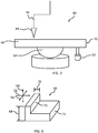
- an exemplary product 60 is shown as a candidate for additive manufacture using the systems and methods disclosed herein.
- the product 60 is a three dimensional object defined in the x direction 62, the y direction 64, and the z direction 66.
- the product 60 is a relatively simple object with a height 68 in the y direction 64, but it will be appreciated that in various applications the geometry will be much more complex.
- the product 60 has a width 70 in the x direction 62 that varies significantly with the height 68 between segment 71 and segment 73. Accordingly, the need to resolve stresses will be different as the width 70 varies at different heights 68.
- the properties of segment 71 may vary significantly from the properties of segment 73 for use in determining the applicable stress relief profile.
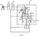
- the build system 20 is illustrated in greater detail and generally includes the stress resolution system 22, which includes a control system 72.
- the control system 72 includes a controller 74.
- the controller 74 controls operation of the build system 20 including of a powder delivery system 80 via the actuator 78, the laser system 26 via the actuator 76, and the height of the build platform 28 via the actuator 82.
- the controller 74 may comprise any number of electronic control modules and receive various input variables of current operating conditions and other parameters.
- the inputs are analyzed and operating parameters such as operation of the laser system 26, ultrasonic transducer 32, and others are computed from the data and applied to the actuators 76, 78 and other responsive devices as appropriate.
- the controller 74 may receive various signals, including from a sensor suite 84 and a position sensor 86, conduct analyses, and send control signals to various destinations, including to the actuators 76, 78 and the ultrasonic transducer 32.
- the actuator 78 may be a linear motor or a combination of motors or other actuators to deliver a layer of powder to the build plate 30.
- the actuator 76 may be a multi-axis locator to move the laser system 26 vertically and horizontally.
- the actuator 82 may be a piston or motor to move the build platform 28 vertically within the cylinder 88.
- the position sensor 86 senses the vertical position of the build platform 28.
- the sensor suite 84 senses various aspects of the product 60 and its build including detecting its physical disposition for detecting distortion. Accordingly, the sensor suite 84 may include position sensors, optical sensors, and other sensors as described below.
- the controller 74 may comprise any number of electronic control modules, including the exemplary modules described below.
- the controller 74 receives information from various sources, process that information, and provides control signals/commands based thereon to effect operation of the build system 20.
- the controller 74 includes a processor 90 and a memory device 92, and is coupled with a storage device 94.
- the processor 90 performs the computation and control functions of the controller 74 and during operation executes one or more programs 96 and may use data 98, each of which may be contained within the storage device 94 and as such, the processor 90 controls the general operation of the controller 74 in executing the processes described herein, such as the processes described further below.
- the memory device 92 may be any type of suitable memory or combination of memory devices capable of storing data, some of which represent executable instructions, used by the controller 74.
- the memory device 92 may store the above-referenced programs 96 along with one or more stored values of the data 98 such as for short-term data access.
- the storage device 94 stores data, such as for long-term data access for use in automatically controlling the build system 20 and may be any suitable type of storage apparatus.
- the storage device 94 comprises a source from which the memory device 92 receives the programs 96 and data 98.
- the programs 96 represent executable instructions, used by the controller 74 in processing information and in controlling the build system 20, including the stress resolution system 22.
- the processor 90 may generate control signals for the build system 20, including the stress resolution system 22 based on the logic, calculations, methods, and/or algorithms.
- the ultrasonic transducer 32 may be activated after a layer is fused into the product 60 or while the fusing is taking place.
- the layers for which the ultrasonic transducer 32 is activated may be predefined and stored in memory and may be recalled according to the location of the build platform 28 as sensed by the position sensor 86.
- the sensor suite 84 may be monitored to determine whether distortion or other aspects of the product 60 indicate activation of the ultrasonic transducer 32 is needed to provide stress resolution.
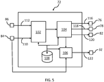
- the control system 72 may include a number of modules to operate the build system 20, including the stress resolution system 22.
- the control system 72 generally includes a stress resolution module 102, an actuator control module 104, an ultrasonic operation module 106, and a datastore 108.
- the control system 72 may include any number of additional modules to control aspects of the build system 20 independent of, or in coordination with, the modules shown in FIG. 5 .
- Inputs may include a signal 110 from the sensor suite 84 and a signal 112 from the position sensor 86.
- Outputs may include a signal 116 to operate the actuator 76 of the laser system 26, a signal 118 to operate the actuator 78 of the powder delivery system 80, a signal 120 to operate the actuator 82 of the build platform 28, and a signal 122 to operate the ultrasonic transducer 32.
- the ultrasonic operation module 106 delivers the signal 122 to the ultrasonic transducer 32 to impart energy through the build platform 28 and the build plate 30 to the in-process product 60 to relieve or avoid stresses therein.
- a process 200 to resolve stresses begins 202 with the geometry and physical properties of the exemplary product 60 being determined 204 according to design requirements. For example, the physical dimensions of the product 60 are determined 204 and the material from which the product 60 will be made is determined 204. Given the geometry, predeterminations 206, 208 may be made by analysis such as based on calculations and/or testing. More specifically, resonant frequencies of the product 60 may be determined 206 for the product 60 as partially built through various build layer stages. The resonant frequencies of the product 60 may be calculated and vary as the height of the build progresses.
- the resonant frequency of the segment 60 will decrease as it becomes higher.
- the resonant frequencies between the segments 71 and 73 will differ substantially.
- Resonant frequencies for given build configurations may be determined with analytical software or by using the results of machine-learning data from prior builds. Once determined 206, the resonance data may be stored, such as in the datastore 108.
- a stress relief profile, including stress relief frequencies and power levels may be determined 208, such as in advance based on modeling, experimentation and/or testing of the product 60.
- the process 200 proceeds to build 210 a layer of the product 60, such as by operation of the actuators 76, 78 via the actuator control module 104 to deposit material and incorporate the layer into the product 60.
- the stress relief frequencies and power levels may be stored, such as in the datastore 108 for given build layers.
- the frequency and power level of the energy supplied by the ultrasonic transducer 32 is tailored to the physical properties of the product 60, including the material used for fabrication, and varies by build level. For example, as shown in FIG.
- the stress resolution module 102 may determine the frequency and power levels based on data retrieved from the datastore 108.
- the ultrasonic transducer 32 is activated according to the stress relief profile at the optimal frequency, power and spectrum for the given material and machine to relieve the residual stresses, such as may arise from metal solidification and cooling.
- the stress relief profile including power and frequency for the ultrasonic excitation may be determined 214, such as by the stress resolution module 102, based on inputs obtained during the build that are read 212, such as from the sensors 84, 86.
- the sensor 86 provides feedback on the build layer of the product 60 and the sensor suite 84 provides information on the product 60, including where a deviation from the design dimensions may be actual or incipient. Sensing distortion enables targeting ultrasonic inputs to individual layers where stress resolution is needed based on the actual build underway.
- the collected data may be stored 216 and/or transmitted. For example, an industrial internet of things application may transmit in-situ measurement data to provide direct input of the ultrasonic cycle to provide customized stress relief treatment based on measurement data showing where and to what degree a part is deforming as an external indication of internal stresses.
- automated adjustments are made to the stress relief profile and stored, such as for use in the determination 208, when distortion or other parameters measured exceed set limits.
- Anticipated build process monitors in the sensor suite 84 may include melt pool sensors, thermal sensors, optical distortion sensors, build plate strain gauges, and others. Data from the sensors is aggregated and implemented into system software that learns as the system matures and incorporates feedback from other connected systems.
- the ultrasonic stress resolution may be used to automatically determine an optimal stress relief profile for a new part (or mix of parts) to be printed.
- an evaluation 220 is made to verify whether ultrasonic stress resolution is needed for the product 60 at the stage of the newly built layer. For example, when the determination 208 is based on a predetermined and stored data, the evaluation 220 outcome is positive when the layer built coincides with one targeted for stress resolution. Also, for example, when the determination 214 concludes that deformation is incipient or started, the evaluation 220 outcome is positive when the layer just built requires stress resolution to correct deformation. When neither is found, the evaluation 220 outcome is negative, and the process 200 returns to build 210 another layer such as by depositing powder by the powder delivery system 80 and activation of the laser system 26.
- the process 200 continues with an evaluation 222 as to whether there is overlap between resonant frequencies of the product 60 in its current configuration and the determined 208, 214 frequency.
- Effectively resolving the stresses in the additive manufactured product 60 includes adapting the frequencies of the ultrasonic input to optimize for the changing harmonic characteristics of a part. This involves exciting at certain frequencies, while excluding other frequencies to be able to both relieve the stresses built up within the build and to avoid damaging vibrations due to hitting certain resonant frequencies.
- the process 200 proceeds to operate 224, the ultrasonic transducer 32 according to the stress relief profile.
- the process 200 reconciles 223 the overlap.
- the frequency delivered by the ultrasonic transducer 32 may be revised to fall outside the resonant frequency range to avoid damaging resonant vibrations. The result is to tune each exposure of ultrasonic cycles throughout the build to selectively excite the system to resolve the stresses while avoiding resonant frequencies.
- the process 200 proceeds to operate 224 the ultrasonic transducer 32, such as by the signal 122 from the ultrasonic operation module 106.
- the build system 20 is widely capable of efficiently adjusting both frequency content and amplitude to adjust to the resonant characteristics of a wide range of build profiles containing any combination of parts to be manufactured.
- a high-power, tunable build system 20 enables delivering the stress resolution energy input through the single ultrasonic transducer 32.
- a cover 95 such as a plate or sheet that covers the metal powderbed during the ultrasonic exposure period may be used to prevent scatter of metal powder out from the build area. Operation of the laser system 26 is suspended when the cover 95 is deployed.
- the cover 95 may be any variation of a sheet, film or plate, and may be pulled by the powder delivery system 80 over the powderbed 99. In other embodiments, the cover 95 may be a sheet, film or plate that is lowered or slid over the powderbed 99.
- the ultrasonic transducer 32 is separately activated to produce a different acoustic profile tailored to settle and compact the metal powderbed 99.
- stress resolution is effected during the additive manufacture of items. Resolving stress while a product is being made improves quality part yield and reduces costs. In addition, part distortion is mitigated or eliminated from occurring.
- the ultrasonic stress resolution system is compact, low-cost, energy efficient and has a relatively small footprint.
- parts may be manufactured with significantly higher speeds and yields for reduced costs and at shorter lead-times. Additionally, the systems and methods disclosed herein enable fabricating components from materials and with geometries that otherwise would not be viable using additive manufacturing.
Landscapes
- Engineering & Computer Science (AREA)
- Chemical & Material Sciences (AREA)
- Materials Engineering (AREA)
- Mechanical Engineering (AREA)
- Physics & Mathematics (AREA)
- Manufacturing & Machinery (AREA)
- Optics & Photonics (AREA)
- Plasma & Fusion (AREA)
- Organic Chemistry (AREA)
- Crystallography & Structural Chemistry (AREA)
- Metallurgy (AREA)
- Thermal Sciences (AREA)
- Health & Medical Sciences (AREA)
- Toxicology (AREA)
- General Physics & Mathematics (AREA)
- Quality & Reliability (AREA)
- Analytical Chemistry (AREA)
- Automation & Control Theory (AREA)
- Child & Adolescent Psychology (AREA)
Abstract
Description
- The present invention generally relates to additive manufacturing, and more particularly relates to a tunable stress resolution approach for the accurate and quality build of complex structures by additive manufacturing.
- Various types of items are being created using additive manufacturing processes. Additive manufacture includes processes such as those that create a component or item by the successive addition of particles, layers or other groupings of a material onto one another. An item is generally built using a computer controlled machine that is programmed with a model which is a digital representation of the item, and includes processes such as 3-D printing. A variety of different additive manufacturing processes are used such as metal printing processes that involve directed energy deposition, laser metal powderbed fusion, material jetting, and other methods.
- During a typical additive manufacturing build, stresses accumulate in the product being built. As the stresses accumulate, undesirable outcomes such as distortion, imperfections, cracking, etc. may occur. The result is that the item being built may not meet dimensional or other quality requirements. This limits the use of additive manufacturing in applications where the item's structural accuracy or dimensional requirements cannot be repeatedly accomplished. For metallic components, stress relief may be attempted post-build using some form of heat treatment. Both the machines to complete the heat treatments and the time to process the parts through the heat treatment stage add both time and cost into the final parts. The stress accumulation problem has been addressed by the development of specialty software that analytically predicts the negative outcomes and adjusts/pre-compensates the build geometry design at those locations to attempt to offset the distortion or creation of such imperfections. Such software may be costly and time consuming to implement. In sum, significant additional costs may arise in additive manufacturing due to a combination of additional processing time and reduced yield. Therefore, the application of additive manufacturing as a viable alternate manufacturing option is limited.
- Accordingly, it is desirable to provide improved systems and methods for managing stresses in additive manufacturing to produce dimensionally accurate and quality parts and to expand the applications of additive manufacturing. Furthermore, other desirable features and characteristics of the present invention will become apparent from the subsequent detailed description of the invention and the appended claims, taken in conjunction with the accompanying drawings and this background of the invention.
- This summary is provided to describe select concepts in a simplified form that are further described in the Detailed Description section. This summary is not intended to identify key or essential features of the claimed subject matter, nor is it intended to be used as an aid in determining the scope of the claimed subject matter.
- Systems and methods are provided that resolve stresses in additive manufacturing. In a number of embodiments, a stress relief profile of an ultrasonic input is determined based on physical properties of the product. Successive layers of a material are added and energy is applied to incorporate the material of each layer into the product. An ultrasonic input is applied according to the determined parameters to resolve stresses as the product is built up. The ultrasonic input is dynamically changed as a function of material thickness along the additive build direction to account for the changes in residual stresses due to increased thermal mass of the built-up part of the product.
- In a number of additional embodiments, an ultrasonic transducer is coupled with a build platform. A powder delivery system adds successive layers of a material to build the product. A laser system adds energy to incorporate the material of each layer into the product. A controller applies a signal to the ultrasonic transducer to produce an ultrasonic input having parameters to resolve stresses as the product is built up, and the ultrasonic input is dynamically changed as a function of material thickness along the additive build direction.
- In other embodiments, a stress relief profile with frequency and amplitude parameters of an ultrasonic input are determined based on physical properties of the product. A powder delivery system adds successive layers of a material to build the product. A laser system adds energy to incorporate the material of each layer into the product. An ultrasonic transducer applies the ultrasonic input with the determined parameters to resolve stress as the product is built up, and varies the frequency and amplitude as a depth of the material incorporated into the product increases. Additionally, the ultrasonic transducer applies an acoustic profile tailored to settle the powder layers on the built-up part thereby resulting in increased densification of the material.
- The present invention will hereinafter be described in conjunction with the following drawing figures, wherein like numerals denote like elements, and wherein:
-
FIG. 1 is a schematic illustration of a system for stress resolution in laser metal powderbed fusion, according to an exemplary embodiment; -
FIG. 2 is a schematic illustration of a system for stress resolution in direct energy deposition, according to an exemplary embodiment; -
FIG. 3 is a perspective illustration of a product for additive manufacture build, according to an exemplary embodiment; -
FIG. 4 is a schematic illustration of a stress resolution system in a first state of build, according to an exemplary embodiment; -
FIG. 5 is a is a diagram of a control system for controlling the stress resolution system ofFIG. 4 , according to an exemplary embodiment; -
FIG. 6 is a flow chart of a method for operation of a stress resolution system, according to an exemplary embodiment; and -
FIG. 7 is a schematic illustration of the stress resolution system ofFIG. 4 in a second state of build, according to an exemplary embodiment. - The following detailed description is merely exemplary in nature and is not intended to limit the invention or the application and uses of the invention. As used herein, the word "exemplary" means "serving as an example, instance, or illustration." Thus, any embodiment described herein as "exemplary" is not necessarily to be construed as preferred or advantageous over other embodiments. All of the embodiments described herein are exemplary embodiments provided to enable persons skilled in the art to make or use the invention and not to limit the scope of the invention which is defined by the claims. Furthermore, there is no intention to be bound by any expressed or implied theory presented in the preceding technical field, background, brief summary, or the following detailed description.
- The various illustrative logical blocks, modules, circuits, and algorithm steps described in connection with the embodiments disclosed herein may be implemented as electronic hardware, computer software, or combinations of both. Some of the embodiments and implementations are described above in terms of functional and/or logical block components (or modules) and various processing steps. Such block components (or modules) may be realized by any number of hardware, software, and/or firmware components configured to perform the specified functions.
- The various illustrative logical blocks, modules, and circuits described in connection with the embodiments disclosed herein may be implemented or performed in a controller with a general purpose processor, a digital signal processor, an application specific integrated circuit, a field programmable gate array or other programmable logic device, discrete gate or transistor logic, discrete hardware components, or any combination thereof designed to perform the functions described herein. A general-purpose processor may be a microprocessor, but in the alternative, the processor may be any conventional processor, controller, microcontroller, or state machine. A processor may also be implemented as a combination of computing devices, e.g., a combination of a digital signal processor and a microprocessor, a plurality of microprocessors, one or more microprocessors in conjunction with a digital signal processor core, or any other such configuration.
- The steps of a process, method or algorithm described in connection with the embodiments disclosed herein may be embodied directly in hardware, in a software module executed by a processor, or in a combination of the two. A software module may reside in any form of storage medium known in the art. An exemplary storage medium may be coupled to the processor such that the processor reads information from, and writes information to, the storage medium. In the alternative, the storage medium may be integral to the processor.
- In a number of embodiments described herein, systems and methods for forming a product by additive manufacturing include determining stress relief profile parameters of an ultrasonic input based on physical properties of the product. A material is deposited by additive manufacturing to build up the product. With materials such as nickel, titanium and aluminum, if not resolved, extreme stresses may accumulate during the additive manufacturing build. As a result, the item being built may crack prior to being able to submit the parts into a post-build stress relief cycle. Accordingly, ultrasonic input is applied to the deposited material to dynamically relieve stresses as the product is built up. In a number of embodiments, the ultrasonic input is varied as a material thickness along the additive build direction depth increases. In additional embodiments, in-situ measurement data may be collected to provide direct input into the ultrasonic cycle to provide customized stress relief treatment based on measurement data showing where and to what degree a part is deforming as an external indication of internal stresses. While the exemplary embodiments described herein may involve particular additive manufacturing processes, the systems and methods of the current disclosure are not limited to those specific processes and may be employed in any number of build applications where dynamic stress relief is desired.
- Referring to
FIG. 1 , abuild system 20 with astress resolution system 22 is schematically illustrated. In this embodiment, thebuild system 20 is a laser metal powderbed fusion system and includes abuild chamber 24 that defines a sealed environment for processing. Alaser system 26 is disposed within thebuild chamber 24 for melting a powder that is selectively deposited one layer at a time. Abuild platform 28 is configured for repositioning at various heights within thebuild chamber 24 during a build process. Abuild plate 30 is attached to thebuild platform 28 to move therewith, and to provide a surface upon which the products being built are disposed. Anultrasonic transducer 32 is coupled with thebuild platform 28. Inside thebuild chamber 24, powder (not shown), is spread on the surface of abuild plate 30. A laser beam from thelaser system 26 is selectively directed on the deposited powder to melt or sinter the layer of powder while also anchoring it to thebuild plate 30. Thebuild platform 28 is then lowered by the depth of one layer. Additional powder is recoated over the surface, such as with a roller, blade or wiper (not shown), and the process repeated for the next layer. In a number of embodiments, the process may be paused briefly at a given layer or layers and theultrasonic transducer 32 is activated according to a stress relief profile at an optimal frequency, power and spectrum for the given material and machine to relieve the residual stresses from metal solidification and cooling, then the additive manufacturing operation is continued. In additional embodiments, theultrasonic transducer 32 is activated according to a stress relief profile concurrent with operation of thelaser system 26 to prevent the creation of stresses. The number of layers in various product builds vary significantly. The build layer interval between stress relief actions decreases as crack propensity increases. For purposes of the present disclosure, stress resolution means relieving stresses that have accumulated and also means avoiding stresses before they accumulate. - Referring to
FIG. 2 , an embodiment with a directedenergy deposition system 40 with astress resolution system 42 is schematically illustrated. The directedenergy deposition system 40 involves focusing an area of intense energy into an introduced material to bond to the surrounding material. The material may be introduced through blowing, spraying, pushing or other means. In this embodiment, a directedenergy deposition head 44 is attached to 5-axismovable head carrier 46. Material is applied to thebuild plate 48 and melted by the directedenergy deposition head 44. Thebuild plate 48 is attached to a 2-axisrotatable build platform 50. Anultrasonic transducer 52 is coupled to thebuild plate 48. During the directed energy deposition, material deposition may be paused briefly and theultrasonic transducer 52 is activated according to a stress relief profile at the optimal frequency, power and spectrum for the given material and machine to relieve the residual stresses from metal solidification and cooling, then normal operation would be restarted. In additional embodiments, the ultrasonic transducer is activated during the deposition of material. This may change the grain structure of the material as the metal solidifies avoiding the creation of stresses altogether. - As illustrated in
FIG. 3 , anexemplary product 60 is shown as a candidate for additive manufacture using the systems and methods disclosed herein. Theproduct 60 is a three dimensional object defined in thex direction 62, they direction 64, and thez direction 66. In this example theproduct 60 is a relatively simple object with aheight 68 in they direction 64, but it will be appreciated that in various applications the geometry will be much more complex. However, even in this example theproduct 60 has awidth 70 in thex direction 62 that varies significantly with theheight 68 betweensegment 71 andsegment 73. Accordingly, the need to resolve stresses will be different as thewidth 70 varies atdifferent heights 68. For example, the properties ofsegment 71 may vary significantly from the properties ofsegment 73 for use in determining the applicable stress relief profile. - With reference to
FIG. 4 , thebuild system 20 is illustrated in greater detail and generally includes thestress resolution system 22, which includes acontrol system 72. Thecontrol system 72 includes acontroller 74. In other embodiments, any number of controllers may be used in place of thecontroller 74. For purposes of the current embodiment, thecontroller 74 controls operation of thebuild system 20 including of apowder delivery system 80 via theactuator 78, thelaser system 26 via theactuator 76, and the height of thebuild platform 28 via theactuator 82. Thecontroller 74 may comprise any number of electronic control modules and receive various input variables of current operating conditions and other parameters. The inputs are analyzed and operating parameters such as operation of thelaser system 26,ultrasonic transducer 32, and others are computed from the data and applied to theactuators controller 74 may receive various signals, including from asensor suite 84 and aposition sensor 86, conduct analyses, and send control signals to various destinations, including to theactuators ultrasonic transducer 32. Theactuator 78 may be a linear motor or a combination of motors or other actuators to deliver a layer of powder to thebuild plate 30. Theactuator 76 may be a multi-axis locator to move thelaser system 26 vertically and horizontally. Theactuator 82 may be a piston or motor to move thebuild platform 28 vertically within thecylinder 88. Theposition sensor 86 senses the vertical position of thebuild platform 28. Thesensor suite 84 senses various aspects of theproduct 60 and its build including detecting its physical disposition for detecting distortion. Accordingly, thesensor suite 84 may include position sensors, optical sensors, and other sensors as described below. - The
controller 74 may comprise any number of electronic control modules, including the exemplary modules described below. Thecontroller 74 receives information from various sources, process that information, and provides control signals/commands based thereon to effect operation of thebuild system 20. Thecontroller 74 includes aprocessor 90 and amemory device 92, and is coupled with astorage device 94. Theprocessor 90 performs the computation and control functions of thecontroller 74 and during operation executes one ormore programs 96 and may usedata 98, each of which may be contained within thestorage device 94 and as such, theprocessor 90 controls the general operation of thecontroller 74 in executing the processes described herein, such as the processes described further below. Thememory device 92 may be any type of suitable memory or combination of memory devices capable of storing data, some of which represent executable instructions, used by thecontroller 74. In the illustrated embodiment, thememory device 92 may store the above-referencedprograms 96 along with one or more stored values of thedata 98 such as for short-term data access. Thestorage device 94 stores data, such as for long-term data access for use in automatically controlling thebuild system 20 and may be any suitable type of storage apparatus. In an exemplary embodiment, thestorage device 94 comprises a source from which thememory device 92 receives theprograms 96 anddata 98. Theprograms 96 represent executable instructions, used by thecontroller 74 in processing information and in controlling thebuild system 20, including thestress resolution system 22. Theprocessor 90 may generate control signals for thebuild system 20, including thestress resolution system 22 based on the logic, calculations, methods, and/or algorithms. - As the build progresses, powderbed 99 is deposited in individual layers on the
build plate 30 and thelaser system 26 selectively energizes the powder to form theproduct 60 according to its design parameters. Theultrasonic transducer 32 may be activated after a layer is fused into theproduct 60 or while the fusing is taking place. The layers for which theultrasonic transducer 32 is activated may be predefined and stored in memory and may be recalled according to the location of thebuild platform 28 as sensed by theposition sensor 86. In other embodiments, thesensor suite 84 may be monitored to determine whether distortion or other aspects of theproduct 60 indicate activation of theultrasonic transducer 32 is needed to provide stress resolution. - As illustrated in
FIG. 5 , thecontrol system 72 may include a number of modules to operate thebuild system 20, including thestress resolution system 22. In embodiments, thecontrol system 72 generally includes astress resolution module 102, anactuator control module 104, anultrasonic operation module 106, and adatastore 108. Thecontrol system 72 may include any number of additional modules to control aspects of thebuild system 20 independent of, or in coordination with, the modules shown inFIG. 5 . Inputs may include asignal 110 from thesensor suite 84 and asignal 112 from theposition sensor 86. Outputs may include asignal 116 to operate theactuator 76 of thelaser system 26, asignal 118 to operate theactuator 78 of thepowder delivery system 80, asignal 120 to operate theactuator 82 of thebuild platform 28, and asignal 122 to operate theultrasonic transducer 32. In general, when a determination is made to operate theultrasonic transducer 32 to resolve stresses, theultrasonic operation module 106, delivers thesignal 122 to theultrasonic transducer 32 to impart energy through thebuild platform 28 and thebuild plate 30 to the in-process product 60 to relieve or avoid stresses therein. - Referring additionally to
FIG. 6 , aprocess 200 to resolve stresses begins 202 with the geometry and physical properties of theexemplary product 60 being determined 204 according to design requirements. For example, the physical dimensions of theproduct 60 are determined 204 and the material from which theproduct 60 will be made is determined 204. Given the geometry,predeterminations product 60 may be determined 206 for theproduct 60 as partially built through various build layer stages. The resonant frequencies of theproduct 60 may be calculated and vary as the height of the build progresses. In a simple example of printing a straight, vertical rectangular bar such as thesegment 73 of theproduct 60, as the build progresses the resonant frequency of thesegment 60 will decrease as it becomes higher. In a build with multiple parts or segments with complex geometries, as the build progresses the resonant properties of the system will change throughout the build. For example, the resonant frequencies between thesegments datastore 108. - A stress relief profile, including stress relief frequencies and power levels may be determined 208, such as in advance based on modeling, experimentation and/or testing of the
product 60. Theprocess 200 proceeds to build 210 a layer of theproduct 60, such as by operation of theactuators actuator control module 104 to deposit material and incorporate the layer into theproduct 60. Where predetermined for a givenproduct 60, the stress relief frequencies and power levels may be stored, such as in thedatastore 108 for given build layers. The frequency and power level of the energy supplied by theultrasonic transducer 32 is tailored to the physical properties of theproduct 60, including the material used for fabrication, and varies by build level. For example, as shown inFIG. 4 , as thesegment 71 is being built, the properties will be different than those as thesegment 73 is being built as shown inFIG. 7 . In the current embodiment, thestress resolution module 102 may determine the frequency and power levels based on data retrieved from thedatastore 108. Theultrasonic transducer 32 is activated according to the stress relief profile at the optimal frequency, power and spectrum for the given material and machine to relieve the residual stresses, such as may arise from metal solidification and cooling. - In a number of embodiments, the stress relief profile including power and frequency for the ultrasonic excitation may be determined 214, such as by the
stress resolution module 102, based on inputs obtained during the build that are read 212, such as from thesensors sensor 86 provides feedback on the build layer of theproduct 60 and thesensor suite 84 provides information on theproduct 60, including where a deviation from the design dimensions may be actual or incipient. Sensing distortion enables targeting ultrasonic inputs to individual layers where stress resolution is needed based on the actual build underway. In addition, the collected data may be stored 216 and/or transmitted. For example, an industrial internet of things application may transmit in-situ measurement data to provide direct input of the ultrasonic cycle to provide customized stress relief treatment based on measurement data showing where and to what degree a part is deforming as an external indication of internal stresses. - In embodiments, automated adjustments are made to the stress relief profile and stored, such as for use in the
determination 208, when distortion or other parameters measured exceed set limits. Anticipated build process monitors in thesensor suite 84 may include melt pool sensors, thermal sensors, optical distortion sensors, build plate strain gauges, and others. Data from the sensors is aggregated and implemented into system software that learns as the system matures and incorporates feedback from other connected systems. In a number of embodiments, by iteratively processing build data against stress resolution inputs and other build parameters, the ultrasonic stress resolution may be used to automatically determine an optimal stress relief profile for a new part (or mix of parts) to be printed. - With the stress relief profile determined 208, 214, an
evaluation 220 is made to verify whether ultrasonic stress resolution is needed for theproduct 60 at the stage of the newly built layer. For example, when thedetermination 208 is based on a predetermined and stored data, theevaluation 220 outcome is positive when the layer built coincides with one targeted for stress resolution. Also, for example, when thedetermination 214 concludes that deformation is incipient or started, theevaluation 220 outcome is positive when the layer just built requires stress resolution to correct deformation. When neither is found, theevaluation 220 outcome is negative, and theprocess 200 returns to build 210 another layer such as by depositing powder by thepowder delivery system 80 and activation of thelaser system 26. - Following a
positive determination 220, theprocess 200 continues with anevaluation 222 as to whether there is overlap between resonant frequencies of theproduct 60 in its current configuration and the determined 208, 214 frequency. Effectively resolving the stresses in the additive manufacturedproduct 60 includes adapting the frequencies of the ultrasonic input to optimize for the changing harmonic characteristics of a part. This involves exciting at certain frequencies, while excluding other frequencies to be able to both relieve the stresses built up within the build and to avoid damaging vibrations due to hitting certain resonant frequencies. When the outcome of theevaluation 222 is negative, and there is no overlap between the determined frequency and the resonant frequency, theprocess 200 proceeds to operate 224, theultrasonic transducer 32 according to the stress relief profile. When theevaluation 222 is positive, meaning there is overlap between the resonant frequency and the determined 208/214 frequency, theprocess 200 reconciles 223 the overlap. For example, the frequency delivered by theultrasonic transducer 32 may be revised to fall outside the resonant frequency range to avoid damaging resonant vibrations. The result is to tune each exposure of ultrasonic cycles throughout the build to selectively excite the system to resolve the stresses while avoiding resonant frequencies. - With the frequency and power of the ultrasonic input determined 208, 214 and the need for stress resolution verified 220, along with any
reconciliation 223, theprocess 200 proceeds to operate 224 theultrasonic transducer 32, such as by thesignal 122 from theultrasonic operation module 106. Thebuild system 20 is widely capable of efficiently adjusting both frequency content and amplitude to adjust to the resonant characteristics of a wide range of build profiles containing any combination of parts to be manufactured. A high-power,tunable build system 20 enables delivering the stress resolution energy input through the singleultrasonic transducer 32. When theprocess 200 determines 226 that theproduct 60 is complete, the process ends 228. When thedetermination 226 is negative, theprocess 200 returns to build 210 an additional layer. - In embodiments with metal powderbed style additive manufacturing, a cover 95 (
FIG. 7 ), such as a plate or sheet that covers the metal powderbed during the ultrasonic exposure period may be used to prevent scatter of metal powder out from the build area. Operation of thelaser system 26 is suspended when thecover 95 is deployed. Thecover 95 may be any variation of a sheet, film or plate, and may be pulled by thepowder delivery system 80 over thepowderbed 99. In other embodiments, thecover 95 may be a sheet, film or plate that is lowered or slid over thepowderbed 99. In some embodiments, followingstep 224, the stress resolution treatment, theultrasonic transducer 32 is separately activated to produce a different acoustic profile tailored to settle and compact themetal powderbed 99. - Through the examples described herein, stress resolution is effected during the additive manufacture of items. Resolving stress while a product is being made improves quality part yield and reduces costs. In addition, part distortion is mitigated or eliminated from occurring. Using ultrasonic energy driven into the components through the build platform, relieves the stresses accumulating in the build and may be addressed before reaching a point of either inducing distortion or ultimately cracking. The ultrasonic stress resolution system is compact, low-cost, energy efficient and has a relatively small footprint. Advantageously, parts may be manufactured with significantly higher speeds and yields for reduced costs and at shorter lead-times. Additionally, the systems and methods disclosed herein enable fabricating components from materials and with geometries that otherwise would not be viable using additive manufacturing.
- While at least one exemplary embodiment has been presented in the foregoing detailed description, it should be appreciated that a vast number of variations exist. It should also be appreciated that the exemplary embodiment or exemplary embodiments are only examples, and are not intended to limit the scope, applicability, or configuration of the invention in any way. Rather, the foregoing detailed description will provide those skilled in the art with a convenient road map for implementing an exemplary embodiment of the invention. It being understood that various changes may be made in the function and arrangement of elements described in an exemplary embodiment without departing from the scope of the invention as set forth in the appended claims.
Claims (15)
- A method of stress resolution in forming a product by additive manufacturing, the method comprising:determining stress resolution profile parameters of an ultrasonic input based on physical properties of the product;adding successive layers of a material to build the product;adding energy to incorporate the material of each layer into the product;applying, by an ultrasonic transducer, the ultrasonic input with the determined stress resolution profile parameters to resolve stress as the product is built up;varying the ultrasonic input as a depth of the material incorporated into the product increases.
- The method of claim 1, wherein the determined stress resolution profile parameters include a determined frequency of the ultrasonic input and comprising:evaluating whether the determined frequency corresponds to a resonant frequency of the product; andmodifying the determined parameters when the determined frequency corresponds to a resonant frequency.
- The method of claim 1, wherein the determined parameters include a determined frequency of the ultrasonic input and a determined amplitude of the ultrasonic input and comprising tuning the ultrasonic input to each individual layer throughout the build of the product.
- The method of claim 1, comprising determining whether ultrasonic input is needed for each individual layer of the build, prior to applying the ultrasonic input.
- The method of claim 4, wherein determining whether ultrasonic input is needed comprises evaluating stored data for each individual layer of the build.
- The method of claim 4, wherein determining whether ultrasonic input is needed comprises measuring, by a sensor, whether the product is distorting.
- The method of claim 1, comprising:determining resonant frequencies for the product at various stages of the build; andavoiding the resonant frequency for the respective layer of the build when applying the ultrasonic input.
- The method of claim 1, comprising applying the ultrasonic input concurrent with adding energy to incorporate the material into the product.
- The method of claim 1, comprising:building the product on a build platform; andcoupling the ultrasonic transducer with the build platform.
- The method of claim 1, comprising:collecting measurement data of the product during the build; andstoring the measurement data to provide customized stress resolution treatment for build of the product.
- A stress resolution system for forming a product by additive manufacturing, the system comprising:a build platform;an ultrasonic transducer coupled with the build platform;a material delivery system configured to add successive layers of a material to build the product;a laser system configured to add energy to incorporate the material of each layer into the product; anda controller configured to:apply a signal to the ultrasonic transducer to produce an ultrasonic input having parameters to resolve stress as the product is built up; andvary the ultrasonic input as a depth of the material incorporated into the product increases.
- The system of claim 11, wherein:the parameters include a determined frequency of the ultrasonic input; andthe controller is configured to:evaluate whether the determined frequency corresponds to a resonant frequency of the product, andmodify the determined parameters when the determined frequency corresponds to a resonant frequency.
- The system of claim 11, wherein the parameters include a determined frequency of the ultrasonic input and a determined amplitude of the ultrasonic input, and wherein the controller is configured to tune the ultrasonic input to each individual layer throughout the build of the product.
- The system of claim 11, wherein the controller is configured to determine whether ultrasonic input is needed for each individual layer of the build, prior to applying the ultrasonic input.
- The system of claim 14, wherein the controller is configured to determine whether ultrasonic input is needed by evaluating stored data for each individual layer of the build.
Applications Claiming Priority (1)
| Application Number | Priority Date | Filing Date | Title |
|---|---|---|---|
| US16/872,618 US11772330B2 (en) | 2020-05-12 | 2020-05-12 | Tunable system and method for stress resolution in additive manufacturing |
Publications (1)
| Publication Number | Publication Date |
|---|---|
| EP3909708A1 true EP3909708A1 (en) | 2021-11-17 |
Family
ID=75674634
Family Applications (1)
| Application Number | Title | Priority Date | Filing Date |
|---|---|---|---|
| EP21170314.5A Withdrawn EP3909708A1 (en) | 2020-05-12 | 2021-04-23 | Tunable system and method for stress resolution in additive manufacturing |
Country Status (2)
| Country | Link |
|---|---|
| US (2) | US11772330B2 (en) |
| EP (1) | EP3909708A1 (en) |
Cited By (1)
| Publication number | Priority date | Publication date | Assignee | Title |
|---|---|---|---|---|
| CN116512594A (en) * | 2023-06-25 | 2023-08-01 | 康硕电气集团有限公司 | Low-stress additive manufacturing equipment |
Families Citing this family (3)
| Publication number | Priority date | Publication date | Assignee | Title |
|---|---|---|---|---|
| US11772330B2 (en) * | 2020-05-12 | 2023-10-03 | Honeywell International Inc. | Tunable system and method for stress resolution in additive manufacturing |
| US20230112233A1 (en) * | 2021-10-11 | 2023-04-13 | Texas Research International, Inc. | Grain Boundary Engineering in Additive Manufacturing |
| DE102022107816A1 (en) | 2022-04-01 | 2023-10-05 | BRANDENBURGISCHE TECHNISCHE UNIVERSITÄT COTTBUS-SENFTENBERG, Körperschaft des öffentlichen Rechts | Manufacturing device and method for the additive manufacturing of a workpiece |
Citations (2)
| Publication number | Priority date | Publication date | Assignee | Title |
|---|---|---|---|---|
| US20070040005A1 (en) * | 2005-08-19 | 2007-02-22 | Siemens Westinghouse Power Corporation | Vibration stress relief of weldments |
| CN110586941A (en) * | 2019-08-26 | 2019-12-20 | 华中科技大学 | Deformation control system and method in metal part additive manufacturing process |
Family Cites Families (16)
| Publication number | Priority date | Publication date | Assignee | Title |
|---|---|---|---|---|
| EP1238715A1 (en) | 2001-03-05 | 2002-09-11 | Prokic Miodrag | Multifrequency ultrasonic structural actuators |
| US7703325B2 (en) * | 2007-08-24 | 2010-04-27 | Weite Wu | Method for relieving residual stress in an object |
| US8082966B2 (en) | 2010-03-12 | 2011-12-27 | Edison Welding Institute, Inc. | System for enhancing sonotrode performance in ultrasonic additive manufacturing applications |
| US20130101728A1 (en) | 2011-10-21 | 2013-04-25 | John J. Keremes | Additive manufacturing in situ stress relief |
| GB201204752D0 (en) | 2012-03-19 | 2012-05-02 | Bae Systems Plc | Additive layer manufacturing |
| US10556270B2 (en) * | 2014-05-01 | 2020-02-11 | United Technologies Corporation | Additive manufacturing system for minimizing thermal stresses |
| US20170059529A1 (en) * | 2015-08-24 | 2017-03-02 | Siemens Energy, Inc. | Adaptive additive manufacturing process using in-situ laser ultrasonic testing |
| EP3147048B1 (en) | 2015-09-28 | 2020-08-05 | Ecole Polytechnique Federale De Lausanne (Epfl) | Method and device for implementing laser shock peening (lsp) or warm laser shock peening (wlsp) during selective laser melting (slm) |
| CN106363173B (en) * | 2016-12-12 | 2018-05-25 | 中国工程物理研究院材料研究所 | A kind of device and its implementation of the increasing material manufacturing of ultrasonic wave auxiliary laser |
| GB2557634B (en) * | 2016-12-14 | 2019-12-11 | Rolls Royce Plc | Methods, apparatus, computer programs & non-transitory computer readable storage mediums for controlling a mobile heatable chamber for additive manufacturing |
| US10857735B1 (en) * | 2017-04-25 | 2020-12-08 | Hrl Laboratories, Llc | Apparatus and method for additive manufacturing and determining the development of stress during additive manufacturing |
| US10234848B2 (en) | 2017-05-24 | 2019-03-19 | Relativity Space, Inc. | Real-time adaptive control of additive manufacturing processes using machine learning |
| CN108176857A (en) * | 2018-03-05 | 2018-06-19 | 广东工业大学 | A kind of metal 3D printing composite manufacturing method and its device |
| RU2691447C1 (en) * | 2018-09-28 | 2019-06-13 | Федеральное государственное бюджетное образовательное учреждение высшего образования "Кубанский государственный технологический университет" (ФГБОУ ВО "КубГТУ") | Method of making part from metal powder material |
| FI131305B1 (en) * | 2019-10-30 | 2025-02-04 | Teknologian Tutkimuskeskus Vtt Oy | Method and apparatus for additive manufacturing |
| US11772330B2 (en) * | 2020-05-12 | 2023-10-03 | Honeywell International Inc. | Tunable system and method for stress resolution in additive manufacturing |
-
2020
- 2020-05-12 US US16/872,618 patent/US11772330B2/en active Active
-
2021
- 2021-04-23 EP EP21170314.5A patent/EP3909708A1/en not_active Withdrawn
-
2023
- 2023-08-14 US US18/449,027 patent/US12409609B2/en active Active
Patent Citations (2)
| Publication number | Priority date | Publication date | Assignee | Title |
|---|---|---|---|---|
| US20070040005A1 (en) * | 2005-08-19 | 2007-02-22 | Siemens Westinghouse Power Corporation | Vibration stress relief of weldments |
| CN110586941A (en) * | 2019-08-26 | 2019-12-20 | 华中科技大学 | Deformation control system and method in metal part additive manufacturing process |
Cited By (1)
| Publication number | Priority date | Publication date | Assignee | Title |
|---|---|---|---|---|
| CN116512594A (en) * | 2023-06-25 | 2023-08-01 | 康硕电气集团有限公司 | Low-stress additive manufacturing equipment |
Also Published As
| Publication number | Publication date |
|---|---|
| US20230391015A1 (en) | 2023-12-07 |
| US11772330B2 (en) | 2023-10-03 |
| US12409609B2 (en) | 2025-09-09 |
| US20210354396A1 (en) | 2021-11-18 |
Similar Documents
| Publication | Publication Date | Title |
|---|---|---|
| US12409609B2 (en) | Tunable system and method for stress resolution in additive manufacturing | |
| EP3751367A1 (en) | Quality assessment feedback control loop for additive manufacturing | |
| JP5666954B2 (en) | Method and apparatus for manufacturing a helical spring by spring winding | |
| CN118305472B (en) | Cutting control method and system of five-axis laser processing equipment | |
| CN110366463B (en) | System and method for controlling microstructure of additively manufactured component | |
| Landers et al. | A review of manufacturing process control | |
| CN113196186A (en) | Automatic parameterization of laser cutting method | |
| Liu et al. | Model predictive control of laser metal deposition | |
| CN114072248B (en) | Spray distance monitoring and control for directed energy deposition additive manufacturing systems | |
| JP7382537B2 (en) | Methods, computer programs and laser cutting systems for smart corner cutting | |
| JP2004086911A (en) | Method, system and storage medium for improving process management | |
| US10857735B1 (en) | Apparatus and method for additive manufacturing and determining the development of stress during additive manufacturing | |
| KR101974722B1 (en) | Device for real-time quality monitoring and quality control for three dimensional additive manufacturing process and the method for the same | |
| Saqib et al. | Investigation of the transient characteristics for laser cladding beads using 420 stainless steel powder | |
| US20200247064A1 (en) | Additive manufacturing system and method and feature extraction method | |
| US20210299753A1 (en) | Method for the Additive Manufacture of a Plurality of Motor Vehicle Components | |
| US11127204B2 (en) | Boundary characteristic-based part processing in support of additive manufacturing | |
| EP4301582A1 (en) | Methods for laser calibration in additive manufacturing systems, and systems configured for same | |
| EP4621520A1 (en) | Parameter adjustment method and parameter adjustment system | |
| CN121165684B (en) | Intelligent control method and system for mold production process | |
| EP4664215A1 (en) | Calibration of a laser processing machine with respect to different excitation frequencies | |
| CN120426919B (en) | Online monitoring method of PCB copper layer thickness based on surface acoustic wave resonance | |
| Scheideler et al. | Quality control of additive manufacturing using statistical prediction methods | |
| CN115916451B (en) | Method, control unit and laser cutting system for calculating space- and time-resolved, combined set-point data sets | |
| CN117897663A (en) | Automated Tuning of Chamber Control and Process Performance Evaluation Methods |
Legal Events
| Date | Code | Title | Description |
|---|---|---|---|
| PUAI | Public reference made under article 153(3) epc to a published international application that has entered the european phase |
Free format text: ORIGINAL CODE: 0009012 |
|
| STAA | Information on the status of an ep patent application or granted ep patent |
Free format text: STATUS: THE APPLICATION HAS BEEN PUBLISHED |
|
| AK | Designated contracting states |
Kind code of ref document: A1 Designated state(s): AL AT BE BG CH CY CZ DE DK EE ES FI FR GB GR HR HU IE IS IT LI LT LU LV MC MK MT NL NO PL PT RO RS SE SI SK SM TR |
|
| B565 | Issuance of search results under rule 164(2) epc |
Effective date: 20211011 |
|
| STAA | Information on the status of an ep patent application or granted ep patent |
Free format text: STATUS: REQUEST FOR EXAMINATION WAS MADE |
|
| RAP3 | Party data changed (applicant data changed or rights of an application transferred) |
Owner name: HONEYWELL INTERNATIONAL INC. |
|
| 17P | Request for examination filed |
Effective date: 20220429 |
|
| RBV | Designated contracting states (corrected) |
Designated state(s): AL AT BE BG CH CY CZ DE DK EE ES FI FR GB GR HR HU IE IS IT LI LT LU LV MC MK MT NL NO PL PT RO RS SE SI SK SM TR |
|
| P01 | Opt-out of the competence of the unified patent court (upc) registered |
Effective date: 20230421 |
|
| GRAP | Despatch of communication of intention to grant a patent |
Free format text: ORIGINAL CODE: EPIDOSNIGR1 |
|
| STAA | Information on the status of an ep patent application or granted ep patent |
Free format text: STATUS: GRANT OF PATENT IS INTENDED |
|
| RIC1 | Information provided on ipc code assigned before grant |
Ipc: G01B 21/16 20060101ALN20250214BHEP Ipc: B23K 9/04 20060101ALN20250214BHEP Ipc: B23K 31/12 20060101ALN20250214BHEP Ipc: G01B 21/20 20060101ALN20250214BHEP Ipc: B06B 1/02 20060101ALN20250214BHEP Ipc: G01B 17/04 20060101ALN20250214BHEP Ipc: B23K 11/00 20060101ALN20250214BHEP Ipc: B23K 10/02 20060101ALN20250214BHEP Ipc: B23K 15/00 20060101ALN20250214BHEP Ipc: B23K 26/342 20140101ALI20250214BHEP Ipc: C22F 3/00 20060101ALI20250214BHEP Ipc: C21D 1/04 20060101ALI20250214BHEP Ipc: G01B 11/16 20060101ALI20250214BHEP Ipc: G01H 13/00 20060101ALI20250214BHEP Ipc: C21D 10/00 20060101ALI20250214BHEP Ipc: C21D 1/30 20060101ALI20250214BHEP Ipc: B33Y 50/02 20150101ALI20250214BHEP Ipc: B33Y 40/20 20200101ALI20250214BHEP Ipc: B33Y 30/00 20150101ALI20250214BHEP Ipc: B33Y 10/00 20150101ALI20250214BHEP Ipc: B23K 20/10 20060101ALI20250214BHEP Ipc: B22F 12/90 20210101ALI20250214BHEP Ipc: B22F 10/50 20210101ALI20250214BHEP Ipc: B22F 10/28 20210101ALI20250214BHEP Ipc: B22F 10/20 20210101AFI20250214BHEP |
|
| RIC1 | Information provided on ipc code assigned before grant |
Ipc: G01B 21/16 20060101ALN20250303BHEP Ipc: B23K 9/04 20060101ALN20250303BHEP Ipc: B23K 31/12 20060101ALN20250303BHEP Ipc: G01B 21/20 20060101ALN20250303BHEP Ipc: B06B 1/02 20060101ALN20250303BHEP Ipc: G01B 17/04 20060101ALN20250303BHEP Ipc: B23K 11/00 20060101ALN20250303BHEP Ipc: B23K 10/02 20060101ALN20250303BHEP Ipc: B23K 15/00 20060101ALN20250303BHEP Ipc: B23K 26/342 20140101ALI20250303BHEP Ipc: C22F 3/00 20060101ALI20250303BHEP Ipc: C21D 1/04 20060101ALI20250303BHEP Ipc: G01B 11/16 20060101ALI20250303BHEP Ipc: G01H 13/00 20060101ALI20250303BHEP Ipc: C21D 10/00 20060101ALI20250303BHEP Ipc: C21D 1/30 20060101ALI20250303BHEP Ipc: B33Y 50/02 20150101ALI20250303BHEP Ipc: B33Y 40/20 20200101ALI20250303BHEP Ipc: B33Y 30/00 20150101ALI20250303BHEP Ipc: B33Y 10/00 20150101ALI20250303BHEP Ipc: B23K 20/10 20060101ALI20250303BHEP Ipc: B22F 12/90 20210101ALI20250303BHEP Ipc: B22F 10/50 20210101ALI20250303BHEP Ipc: B22F 10/28 20210101ALI20250303BHEP Ipc: B22F 10/20 20210101AFI20250303BHEP |
|
| RIC1 | Information provided on ipc code assigned before grant |
Ipc: G01B 21/16 20060101ALN20250310BHEP Ipc: B23K 9/04 20060101ALN20250310BHEP Ipc: B23K 31/12 20060101ALN20250310BHEP Ipc: G01B 21/20 20060101ALN20250310BHEP Ipc: B06B 1/02 20060101ALN20250310BHEP Ipc: G01B 17/04 20060101ALN20250310BHEP Ipc: B23K 11/00 20060101ALN20250310BHEP Ipc: B23K 10/02 20060101ALN20250310BHEP Ipc: B23K 15/00 20060101ALN20250310BHEP Ipc: B23K 26/342 20140101ALI20250310BHEP Ipc: C22F 3/00 20060101ALI20250310BHEP Ipc: C21D 1/04 20060101ALI20250310BHEP Ipc: G01B 11/16 20060101ALI20250310BHEP Ipc: G01H 13/00 20060101ALI20250310BHEP Ipc: C21D 10/00 20060101ALI20250310BHEP Ipc: C21D 1/30 20060101ALI20250310BHEP Ipc: B33Y 50/02 20150101ALI20250310BHEP Ipc: B33Y 40/20 20200101ALI20250310BHEP Ipc: B33Y 30/00 20150101ALI20250310BHEP Ipc: B33Y 10/00 20150101ALI20250310BHEP Ipc: B23K 20/10 20060101ALI20250310BHEP Ipc: B22F 12/90 20210101ALI20250310BHEP Ipc: B22F 10/50 20210101ALI20250310BHEP Ipc: B22F 10/28 20210101ALI20250310BHEP Ipc: B22F 10/20 20210101AFI20250310BHEP |
|
| INTG | Intention to grant announced |
Effective date: 20250324 |
|
| STAA | Information on the status of an ep patent application or granted ep patent |
Free format text: STATUS: THE APPLICATION IS DEEMED TO BE WITHDRAWN |
|
| 18D | Application deemed to be withdrawn |
Effective date: 20250725 |