EP3909670A1 - Production method for fermented malt beverage and filtration method for fermented liquid - Google Patents
Production method for fermented malt beverage and filtration method for fermented liquid Download PDFInfo
- Publication number
- EP3909670A1 EP3909670A1 EP20738724.2A EP20738724A EP3909670A1 EP 3909670 A1 EP3909670 A1 EP 3909670A1 EP 20738724 A EP20738724 A EP 20738724A EP 3909670 A1 EP3909670 A1 EP 3909670A1
- Authority
- EP
- European Patent Office
- Prior art keywords
- fermented liquid
- cross
- ceramic membrane
- filtration
- membrane filter
- Prior art date
- Legal status (The legal status is an assumption and is not a legal conclusion. Google has not performed a legal analysis and makes no representation as to the accuracy of the status listed.)
- Granted
Links
Images




Classifications
-
- B—PERFORMING OPERATIONS; TRANSPORTING
- B01—PHYSICAL OR CHEMICAL PROCESSES OR APPARATUS IN GENERAL
- B01D—SEPARATION
- B01D63/00—Apparatus in general for separation processes using semi-permeable membranes
- B01D63/06—Tubular membrane modules
- B01D63/066—Tubular membrane modules with a porous block having membrane coated passages
-
- B—PERFORMING OPERATIONS; TRANSPORTING
- B01—PHYSICAL OR CHEMICAL PROCESSES OR APPARATUS IN GENERAL
- B01D—SEPARATION
- B01D65/00—Accessories or auxiliary operations, in general, for separation processes or apparatus using semi-permeable membranes
- B01D65/02—Membrane cleaning or sterilisation ; Membrane regeneration
-
- B—PERFORMING OPERATIONS; TRANSPORTING
- B01—PHYSICAL OR CHEMICAL PROCESSES OR APPARATUS IN GENERAL
- B01D—SEPARATION
- B01D71/00—Semi-permeable membranes for separation processes or apparatus characterised by the material; Manufacturing processes specially adapted therefor
- B01D71/02—Inorganic material
-
- C—CHEMISTRY; METALLURGY
- C12—BIOCHEMISTRY; BEER; SPIRITS; WINE; VINEGAR; MICROBIOLOGY; ENZYMOLOGY; MUTATION OR GENETIC ENGINEERING
- C12C—BEER; PREPARATION OF BEER BY FERMENTATION; PREPARATION OF MALT FOR MAKING BEER; PREPARATION OF HOPS FOR MAKING BEER
- C12C7/00—Preparation of wort
- C12C7/14—Lautering, i.e. clarifying wort
- C12C7/16—Lautering, i.e. clarifying wort by straining
- C12C7/165—Lautering, i.e. clarifying wort by straining in mash filters
-
- B—PERFORMING OPERATIONS; TRANSPORTING
- B01—PHYSICAL OR CHEMICAL PROCESSES OR APPARATUS IN GENERAL
- B01D—SEPARATION
- B01D2311/00—Details relating to membrane separation process operations and control
- B01D2311/04—Specific process operations in the feed stream; Feed pretreatment
-
- B—PERFORMING OPERATIONS; TRANSPORTING
- B01—PHYSICAL OR CHEMICAL PROCESSES OR APPARATUS IN GENERAL
- B01D—SEPARATION
- B01D2311/00—Details relating to membrane separation process operations and control
- B01D2311/26—Further operations combined with membrane separation processes
- B01D2311/2688—Biological processes
-
- B—PERFORMING OPERATIONS; TRANSPORTING
- B01—PHYSICAL OR CHEMICAL PROCESSES OR APPARATUS IN GENERAL
- B01D—SEPARATION
- B01D2315/00—Details relating to the membrane module operation
- B01D2315/10—Cross-flow filtration
-
- B—PERFORMING OPERATIONS; TRANSPORTING
- B01—PHYSICAL OR CHEMICAL PROCESSES OR APPARATUS IN GENERAL
- B01D—SEPARATION
- B01D61/00—Processes of separation using semi-permeable membranes, e.g. dialysis, osmosis or ultrafiltration; Apparatus, accessories or auxiliary operations specially adapted therefor
- B01D61/14—Ultrafiltration; Microfiltration
Definitions
- the present invention relates to a method of producing a fermented malt beverage and a method of filtering a fermented liquid.
- Fermented malt beverages such as beer and happoushu that use malt as a raw material are produced by adding yeast to a raw material liquid, fermenting the mixture, and then removing the yeast in a filtration step.
- silica gel, polyvinylpolypyrrolidone (PVPP) or the like is generally used as a stabilizer in order to adsorb and remove causative substances of turbidity.
- PVPP polyvinylpolypyrrolidone
- diatomaceous earth filtration has been conventionally used.
- cross-flow filtration which can suppress loss when switching varieties, generation of waste, etc. and is easy to handle, has come to be used.
- a polymer membrane filter In the cross-flow filtration of fermented malt beverages, a polymer membrane filter is usually used.
- Japanese Patent Laid-open Publication No. S62(1987)-3287 describes that a ceramic membrane filter is used for filtering beer.
- the filter has not been put into practical use because a sufficient permeation flux cannot be obtained.
- TMP transmembrane pressure
- an object of the present invention is to provide a method of producing a fermented malt beverage, which includes a cross-flow filtration step using a ceramic membrane filter, suppresses a rapid increase in transmembrane pressure, and enables a long-term filtration operation.
- the first aspect is a method of producing a fermented malt beverage, which comprises cross-flow filtering a fermented liquid containing malt as a raw material.
- the cross-flow filtration is performed through a monolithic ceramic membrane filter disposed apart from a flow path of the fermented liquid, including a slit having an opening in its side surface, and having a membrane pore size of 0.6 ⁇ m or more and 0.9 ⁇ m or less, and the fermented liquid contains silica gel having a drying loss of 40% or more.
- a permeation flux may be 30 L/m 2 /h or more.
- the cross-flow filtration may be performed with a transmembrane pressure of 0.6 MPa or less.
- the cross-flow filtration may include increasing the transmembrane pressure to 0.3 MPa or more.
- the cross-flow filtration may be performed continuously for 3 hours or more using the same monolithic ceramic membrane filter.
- a log reduction value LRV may be 5 or more relative to Lactobacillus brevis.
- the production method may not comprise at least one of a disinfection treatment and a sterilization treatment of the fermented liquid other than the cross-flow filtration. In one aspect, the production method may not comprise filtration of the fermented liquid other than the cross-flow filtration. In one aspect, the production method may not comprise a heat sterilization step of the fermented liquid. In one aspect, in the production method, the log reduction value LRV may be 5 or more relative to Lactobacillus brevis. In one embodiment, the cross-flow filtration may be performed through two or more monolithic ceramic membrane filters connected in parallel via a flow path. In one embodiment, the cross-flow filtration may be performed at a temperature of the fermented liquid of -2°C or higher and 3°C or lower.
- the second aspect is a method of filtering a fermented liquid, which includes cross-flow filtering the fermented liquid containing malt as a raw material.
- the cross-flow filtration is performed through a monolithic ceramic membrane filter disposed apart from a flow path of the fermented liquid, including a slit having an opening in its side surface, and having a membrane pore size of 0.6 ⁇ m or more and 0.9 ⁇ m or less, and the fermented liquid contains silica gel having a drying loss of 40% or more.
- the cross-flow filtration is continuously performed by sequentially switching two or more monolithic ceramic membrane filters switchably connected to the flow path of the fermented liquid, and includes allowing the fermented liquid to permeate through at least one of the monolithic ceramic membrane filters and performing clean-in-place cleaning of at least one other of the monolithic ceramic membrane filters, and switching the flow path of the fermented liquid to allow the fermented liquid to permeate through the monolithic ceramic membrane filter after the clean-in-place cleaning and performing clean-in-place cleaning of the monolithic ceramic membrane filter through which the fermented liquid has permeated, and a time during which the fermented liquid is permeated may be longer than a time required for the clean-in-place cleaning.
- a method of producing a fermented malt beverage which includes a cross-flow filtration step using a ceramic membrane filter, suppresses a rapid increase in transmembrane pressure, and enables a long-term filtration operation.
- step in addition to an independent step, the term “step” also refers to a step that achieves an intended object of the step even when the step cannot be clearly distinguished from other steps.
- Numeric ranges indicated by “to” are ranges that include the minimum and maximum values each stated before and after the "to.”
- the content of each component in the composition unless otherwise noted, is taken to mean the total amount of these substances present in the composition.
- an embodiment of the present invention will be described in detail. However, the following embodiment exemplifies a method of producing a fermented malt beverage for embodying the technical idea of the present invention, and the present invention is not limited to the method of producing a fermented malt beverage, and the like shown below.
- the method of producing a fermented malt beverage comprises a filtration step of cross-flow filtering a fermented liquid containing malt as a raw material.
- the cross-flow filtration is performed through a monolithic ceramic membrane filter having a membrane pore size of 0.6 ⁇ m or more and 0.9 ⁇ m or less.
- the monolithic ceramic membrane filter is disposed apart from a flow path of the fermented liquid and includes a slit having an opening in its side surface.
- the fermented liquid used for cross-flow filtration contains silica gel having a drying loss of 40% or more.
- the production steps other than the filtration step for example, a mashing step, a fermentation step, a packaging step, and the like are not particularly limited.
- the fermented liquid containing specific silica gel is permeated using a monolithic ceramic membrane filter having a pore size of the membrane within a specific range and including a slit through which a filtrate is removed, so that a rapid increase in transmembrane pressure is suppressed to enable a long-term filtration operation. Since yeast and microorganisms other than yeast are efficiently removed from the fermented liquid, it is not necessary to subject a filtrate to disinfection treatment, sterilization treatment, etc. like an additional filtration step, and the production step is simplified.
- the fermented malt beverage to be produced is a beverage produced, including a step of fermenting a raw material containing malt, and examples thereof include beers, happoushu, effervescent alcoholic beverages called a new genre, and refreshing drinks from which alcohol is removed from these beverages.
- the beer may be beer defined by the Japanese Liquor Tax Act (Act No. 59 of 2018), the Japanese Liquor Tax Act Enforcement Order (Cabinet Order No. 136 of 2018), and the Ordinance for Enforcement of the Japanese Liquor Tax Act (Ordinance of the Ministry of Finance No. 19 of 2018), is not limited to these beers, and includes beer as a general concept.
- the beer in the above laws refers to the following alcoholic beverages with an alcohol content of less than 20%.
- Happoushu includes alcoholic beverages, using malt or wheat as part of raw materials, other than beer and beer-like effervescent beverages, and the new genre is a product obtained by adding spirits to happoushu.
- the fermented liquid is a liquid obtained by alcohol-fermenting a raw material liquid containing sugar with yeast.
- the fermented liquid contains yeast, protein, polyphenols, etc., and may unintentionally contain microorganisms other than yeast. Lactic acid bacteria and the like can be considered as microorganisms that can be contained in addition to yeast.
- At least malt is used as a raw material for preparation of the raw material liquid
- a plant-derived protein such as soybean protein
- filterability may deteriorate if a use ratio of dark-colored malt roasted at 100°C or higher is high.
- the fermented liquid may be prepared by fermenting a raw material liquid having a desired configuration with yeast by a commonly used method.
- Silica gel having a drying loss of 40% or more is added to the fermented liquid obtained by fermenting the raw material liquid by a conventional method.
- the fermented liquid is then subjected to the filtration step, and at least a portion of at least one substance selected from the group consisting of yeast, other microorganisms other than yeast, proteins, polyphenols and the like is removed by cross-flow filtration using the monolithic ceramic membrane filter including a slit.
- the fermented liquid subjected to the filtration step contains silica gel having a drying loss of 40% or more, preferably a drying loss of 50% or more.
- Silica gel is contained as a stabilizer, for example, in the fermented liquid. From the fermented liquid containing silica gel, proteins and the like that cause turbidity are adsorbed/removed from the fermented liquid by the filtration step. Since the fermented liquid contains silica gel having a drying loss of 40% or more and a high water content, the rapid increase in transmembrane pressure is suppressed in the filtration step.
- the drying loss of silica gel is a value measured in accordance with ISO 787-2: 1981 (JIS K 5101-15-1: 2004) and expressed as a mass fraction (%) by the following formula when the silica gel is dried at 105°C for 2 hours. 100 ⁇ m 0 ⁇ m 1 m 0
- m 0 mass of sample (g)
- m 1 mass of sample after drying (g).
- silica gel having a drying loss of 40% or more include BRITESORB (registered trademark) manufactured by PQ Corporation and DARACLAR (registered trademark) manufactured by Grace WR & Co.
- silica gel for example, it is possible to use silica gel having a volume-based 50% particle diameter (median diameter; d50) of 15 ⁇ m or more and 45 ⁇ m or less and a drying loss of 40% or more and 70% or less.
- a number-based 10% particle diameter (d10) is larger than the pore size of the ceramic membrane filter.
- the number-based 10% particle diameter (d10) of silica gel is, for example, 1.0 ⁇ m or more, preferably 2.0 ⁇ m or more, and, for example, 5.0 ⁇ m or less.
- the number-based 50% particle diameter of silica gel is, for example, 3.0 ⁇ m or more, preferably 5.0 ⁇ m or more, and, for example, 15.0 ⁇ m or less, preferably 10.0 ⁇ m or less.
- the volume-based 50% particle diameter of silica gel is, for example, 4.0 ⁇ m or more, preferably 15.0 ⁇ m or more, and, for example, 45.0 ⁇ m or less, preferably 35.0 ⁇ m or less.
- Any percent particle diameter of silica gel may be measured using a commercially available particle diameter distribution measuring device, particle counter, or the like in accordance with ISO 13320: 2009 (JIS Z 8825: 2013).
- a specific surface area of silica gel is, for example, 300 m 2 /g or more, preferably 500 m 2 /g or more, and for example 1000 m 2 /g or less, preferably 850 m 2 /g or less.
- proteins are sufficiently removed in the filtration step.
- a content of silica gel is, for example, preferably 100 ppm or more, more preferably 200 ppm or more, still more preferably 300 ppm or more, based on the fermented liquid.
- the silica gel content is, for example, preferably 2000 ppm or less, more preferably 1200 ppm or less, and still more preferably 1000 ppm or less.
- the silica gel content of 1 ppm corresponds to 1 mg/L.
- the silica gel content is equal to or more than the above lower limit value, proteins that cause turbidity can be sufficiently adsorbed/removed.
- the silica gel content is equal to or less than the above upper limit value, the deterioration of the filterability is suppressed, and foam retention of the fermented malt beverage is well maintained.
- silica hydrogel having a relatively large drying loss (moisture content) of 40% or more is used as silica gel.
- silica gel includes silica xerogel having a relatively small drying loss (moisture content).
- silica xerogel having a drying loss of 10% or less in the method of producing a fermented malt beverage.
- SYLOPUTE registered trademark
- CARPLEX registered trademark
- Evonik Industries Ag etc.
- the fermented liquid may contain silica xerogel as long as the effects of the present invention are not impaired.
- the content thereof is, for example, 500 ppm or less, preferably 300 ppm or less, more preferably 150 ppm or less, and still more preferably less than 1 ppm. That is, it is preferable that the fermented liquid does not substantially contain silica xerogel.
- the fermented liquid may contain polyvinylpolypyrrolidone (PVPP) as a stabilizer for adsorbing/removing turbidity-causing substances.
- PVPP polyvinylpolypyrrolidone
- BASF BASF
- Polyclar registered trademark manufactured by Ashland, etc. are commercially available.
- the content thereof is, for example, 300 ppm or less, preferably 200 ppm or less, more preferably 150 ppm or less, and still more preferably less than 1 ppm. That is, it is preferable that the fermented liquid does not substantially contain polyvinylpolypyrrolidone.
- the ceramic membrane filter itself has a pressure resistance of 1 MPa or more, considering load on a pump, a supply pressure of pneumatic instrumentation, equipment maintenance, etc., the transmembrane pressure during the filtration step is, for example, less than 1 MPa, preferably 0.6 MPa or less, and more preferably 0.5 MPa or less.
- silica hydrogel has lower adsorptivity to polyphenols than that of PVPP, it is considered that influence on a flavor of fermented malt beverage is less than that when PVPP is used.
- a monolithic ceramic membrane filter provided with a slit (hereinafter, also simply referred to as "ceramic membrane filter”) is used.
- the ceramic membrane filter is superior in heat resistance, corrosion resistance, and durability to a polymer membrane filter. Since it is possible to perform chemical cleaning, back pressure cleaning, and regeneration by baking, the labor and cost of replacing the membrane filter can be reduced. Since the ceramic membrane filter has high strength, cross-flow filtration at a high filtration pressure or circulation flow velocity is possible, and, in addition, the ceramic membrane filter has such a characteristic that a pore size distribution is sharp and separation accuracy is high.
- the monolithic ceramic membrane filter has a cylindrical shape or a prismatic shape, and is provided with a stock solution channel penetrating between two end surfaces (for example, bottom surface and top surface) orthogonal to a stretching direction.
- a stock solution to be filtered is filtered by a membrane layer provided surrounding the stock solution channel while flowing through the stock solution channel and passes through a substrate material layer, and a filtered solution flows out to a permeation side.
- a cross-sectional shape of the stock solution channel may be any of a circular shape, an elliptical diameter, an oval shape, a polygonal shape, and the like.
- the ceramic membrane filter is configured by, for example, providing a membrane layer having a desired pore size (average pore diameter) on a porous substrate material layer.
- An intermediate layer may be provided between the substrate material layer and the membrane layer, if necessary.
- the ceramic membrane filter used in the present embodiment is provided with a slit (hereinafter, also referred to as a liquid collecting slit).
- the slit is provided in the substrate material layer so as not to intersect the stock solution channel and has an opening on a surface of the ceramic membrane filter.
- the opening of the slit may be provided on a side surface of the ceramic membrane filter, for example, and the slit may be provided so as to penetrate between the side surfaces.
- a cross-sectional shape of the slit may be, for example, a rectangular shape, and may be a substantially circular shape, an elliptical diameter, an oval shape, a polygonal shape, or the like.
- the slit may be provided, for example, in the substrate material layer so as to be substantially parallel to the stock solution channel and may be connected to at least one liquid collection channel having no opening on its end surface.
- a cross-sectional shape of the liquid collection channel may be any of a circular shape, an elliptical diameter, an oval shape, a polygonal shape, and the like.
- FIG. 1 is a schematic view showing a configuration of a general monolithic ceramic membrane filter 100.
- a stock solution to be filtered enters an inside of each stock solution channel 10 which is a flow path, and is filtered by seeping out from the inside of the stock solution channel 10 through a membrane layer 20 and a substrate material layer 30.
- no slit is provided in the substrate material layer 30.
- FIG. 2 is a schematic view showing an example of a configuration of a monolithic ceramic membrane filter 200 having a slit according to the present embodiment.
- FIG. 2 is a partially reorganized drawing taken from the website of METAWATER Co., Ltd. (http://www.metawater.co.jp/news/2017/11/20171125-1.html).
- a plurality of the stock solution channels 10 are provided as through holes penetrating in a length direction of the monolithic ceramic membrane filter 200 and having a substantially circular cross section.
- the plurality of the stock solution channels 10 are arranged substantially parallel to each other in a direction substantially orthogonal to the length direction.
- a liquid collection channel 40 for collecting a filtrate is formed as a columnar hole having a substantially circular cross section without having an opening on its end surface.
- a plurality of the liquid collection channels 40 are provided so as not to intersect the stock solution channel 10 and substantially parallel to the stock solution channel 10. That is, the liquid collection channel 40 is provided apart from the stock solution channel 10 by the substrate material layer 30.
- a liquid collecting slit 50 is connected to the plurality of liquid collection channels 40 arranged substantially parallel to a stretching direction of the liquid collecting slit 50, and is provided with an opening 55 on a side surface of the monolithic ceramic membrane filter 200.
- the liquid collecting slit 50 is disposed so as to penetrate the substrate material layer 30 from one side surface side to the other side surface side of the monolithic ceramic membrane filter 200.
- the six liquid collecting slits 50 are arranged; however, the number of liquid collecting slits arranged may be, for example, 2 to 8.
- the monolithic ceramic membrane filter 200 has, in the substrate material layer 30, the liquid collecting slit 50 connected to the liquid collection channel 40 and having the opening 55 on the side surface. As a result, a maximum value of a distance from the surface of the membrane layer 20 to the surface on the permeation side is reduced, the surface area on the permeation side increases, and a high permeation flux can be achieved.
- the permeation flux of the monolithic ceramic membrane filter in the filtration step is, for example, 30 L/m 2 /h or more, preferably 40 L/m 2 /h or more, more preferably 50 L/m 2 /h or more, and still more preferably more than 50 L/m 2 /h.
- the permeation flux is equal to or more than the above lower limit value, it is possible to reduce a membrane area of the monolithic ceramic membrane filter and the number of monolithic ceramic membrane filters used with respect to a target permeation flow rate (L/h).
- the permeation flux is, for example, 100 L/m 2 /h or less, preferably 80 L/m 2 /h or less, and more preferably 70 L/m 2 /h or less.
- the permeation flux is equal to or less than the upper limit value, a rate of increase in transmembrane pressure is further suppressed, and the load on the pump installed on a primary side of the ceramic membrane filter due to the increase in transmembrane pressure is further reduced.
- time until an upper limit of a pump discharge pressure is reached is further extended, and a time during which continuous filtration can be performed using the same ceramic membrane filter is longer.
- the pore size of the ceramic membrane filter is, for example, 0.6 ⁇ m or more and 0.9 ⁇ m or less, and preferably 0.6 ⁇ m or more and 0.8 ⁇ m or less.
- the rate of increase in transmembrane pressure can be effectively suppressed, and continuous operation of the filtration step for a long time becomes possible.
- the pore size of the ceramic membrane filter is equal to or less than the above upper limit value, sterilization performance of the ceramic membrane filter is sufficiently maintained, and it is not necessary to carry out disinfection treatment, sterilization treatment, etc. of the fermented liquid other than cross-flow filtration. The sterilization performance of the ceramic membrane filter will be described later.
- the pore size of the ceramic membrane filter may be measured using a commercially available porosimeter of mercury intrusion type, for example, in accordance with JIS R 1655: 2003 "Test methods for pore size distribution of fine ceramic green body by mercury porosimetry".
- JIS R 1655: 2003 "Test methods for pore size distribution of fine ceramic green body by mercury porosimetry”.
- a peak value corresponding to the membrane layer read from a frequency distribution curve for a pore size that is obtained from test results by a test method specified in JIS R 1655: 2003 is defined as the pore size.
- the rate of increase in transmembrane pressure may increase.
- the silica xerogel contains almost no particles having a particle diameter smaller than the pore size of the ceramic membrane filter, the rate of increase in transmembrane pressure may increase, for example even when the number-based 10% particle diameter (d10) is larger than the pore size.
- the sterilization performance of the ceramic membrane filter may be evaluated by a log reduction value (LRV) obtained by a bacterial challenge test.
- the log reduction value of the ceramic membrane filter is, for example, 5 or more, preferably 6 or more, more preferably 7 or more, and still more preferably 9 or more.
- the log reduction value of the filtration step using the ceramic membrane filter is 5 or more, the log reduction value as the entire production step can be easily set to 5 or more.
- the added sterilization treatment, disinfection treatment, etc. of the fermented liquid are generally carried out by, for example, an additional filtration treatment, heat sterilization treatment, etc.
- the bacterial challenge test is evaluated by the sterilization performance to microorganism which is mixed into a fermented malt beverage such as beer to cause turbidity, for example, Lactobacillus brevis, a lactic acid bacterium belonging to genus Lactobacillus, and is a typical beer-spoilage microorganism.
- the bacterial challenge test may be carried out by the following method.
- a test bacterium (Lactobacillus brevis NBRC 107147) is inoculated on MRS agar medium (Lactobacilli MRS Agar (Difco)), cultured at 30°C for 3 days, and the obtained microbial cell body is inoculated on MRS liquid medium (Lactobacilli MRS Broth (Difco)) and cultured at 30°C for 2 days. After centrifuging this culturing solution, the obtained microbial cell body is suspended in sterilized purified water so that the number of bacteria per 1 mL is about 10 10 to obtain a bacterial solution.
- the bacterial solution is added to and mixed with 40 L of pure water so that the number of bacteria per 1 mL is about 10 7 , to prepare a test solution.
- a 1000 mL of the test solution is made to pass through a sample under conditions of 0.10, 0.15 and 0.20 MPa, to collect the passing water.
- the number of live bacterial cells (the number of test bacteria) of the test solution before passing through the sample is calculated by converting the number of live bacterial cells per 1 mL, measured by a flat plate smear culture method using MRS agar medium, into the number per 1000 mL.
- the number of live bacterial cells (the number of leaked bacteria) of the passing water is measured by a membrane filter method (30°C, culture for 3 days).
- LRV log 10 A/B
- A the number of test bacteria
- B the number of leaked bacteria. If the number of leaked bacteria is 0, 1 is used for B, and the evaluation is made as LRV ⁇ log 10 A.
- the material of the monolithic ceramic membrane filter used in the cross-flow filtration step is not particularly limited, and it is common to use high-purity alumina (Al 2 O 3 ) for the substrate material layer, the intermediate layer, and the membrane layer.
- high-purity alumina Al 2 O 3
- the membrane area of the ceramic membrane filter, the surface area on the permeation side, the maximum value of the distance from the membrane surface to the surface on the permeation side, and the like may be selected according to a target filtration flow rate (L/h) and the like.
- a target filtration flow rate L/h
- the membrane area of the ceramic membrane filter is, for example, 0.8 m 2 or more and 4.0 m 2 or less, and preferably 1.5 m 2 or more and 3.0 m 2 or less
- the surface area on the permeation side is, for example, 0.22 m 2 or more and 0.70 m 2 or less, and preferably 0.40 m 2 or more and 0.55 m 2 or less.
- a ratio of the maximum value of the distance from the membrane surface to the surface on the permeation side to an outer diameter of the monolithic ceramic membrane filter is, for example, 0.06 or more and 0.31 or less, and preferably 0.12 or more and 0.23 or less.
- a ratio of the surface area on the permeation side to the membrane area of the ceramic membrane filter is, for example, 0.09 or more and 0.30 or less, and preferably 0.15 or more and 0.25 or less.
- the cross-flow filtration in the filtration step may be carried out using a plurality of monolithic ceramic filters.
- the plurality of monolithic ceramic filters may be connected in parallel or in series via a flow path.
- the plurality of monolithic ceramic filters preferably include at least monolithic ceramic filters connected in parallel.
- FIGS. 3 and 4 An arrangement example of a plurality of monolithic ceramic membrane filters used for cross-flow filtration of the fermented liquid will be described with reference to FIGS. 3 and 4 .
- FIG. 3 all the four monolithic ceramic membrane filters 200 are arranged in a parallel relationship, and four flow paths branched from one flow path are connected to each of the monolithic ceramic membrane filters 200.
- FIG. 4 two units consisting of the two monolithic ceramic membrane filters 200 arranged in parallel are arranged in series. In each unit, the two monolithic ceramic membrane filters 200 are arranged in parallel, and two flow paths branched from one flow path are connected to each of the monolithic ceramic membrane filters 200.
- the monolithic ceramic membrane filters 200 are arranged in series as a unit, and one flow path is connected to the inflow side and the outflow side of each unit.
- cross-flow filtration may be continuously performed by sequentially switching two or more monolithic ceramic membrane filters switchably connected to the flow path of the fermented liquid.
- the filtration step includes allowing the fermented liquid to permeate through at least one monolithic ceramic membrane filter and performing clean-in-place cleaning of at least one other monolithic ceramic membrane filter, and switching the flow path of the fermented liquid to allow the fermented liquid to permeate through the monolithic ceramic membrane filter after the clean-in-place cleaning and performing clean-in-place cleaning of the monolithic ceramic membrane filter through which the fermented liquid has permeated.
- it is preferable that a time required for the permeation of the fermented liquid is longer than a time required for the clean-in-place cleaning.
- FIG. 5 the fermented liquid containing silica gel flows along the flow path shown by the solid line and is cross-flow filtered by a filtration device 220 including the monolithic ceramic membrane filter.
- a filtration device 220 including the monolithic ceramic membrane filter is subjected to clean-in-place (CIP) cleaning.
- CIP clean-in-place
- the fermented liquid containing silica gel is supplied to the filtration device 210 subjected to clean-in-place cleaning along the flow path shown by the solid line, and the fermented liquid is cross-flow filtered.
- the filtration device 220 used for the cross-flow filtration of the fermented liquid the cleaning liquid and water flow along the flow path shown by the broken line to perform clean-in-place cleaning.
- the clean-in-place cleaning is performed by, for example, supplying a first cleaning agent 410, a second cleaning agent 420, a third cleaning agent 430, and water 440 to the flow path, and allowing at least one of the cleaning agent and water to permeate through the filtration devices 210 and 220.
- a first cleaning agent 410 for example, an alkaline aqueous solution such as an aqueous solution of sodium hydroxide; an oxidizing cleaning solution such as an aqueous solution of sodium hypochlorite, hydrogen peroxide, and persulfate; an acidic aqueous solution such as nitric acid, phosphoric acid, and the like are used.
- the cleaning agent may be used alone or in combination of two or more.
- the cleaning agent may be heated to 30°C or higher and 60°C or lower by a heating device 450.
- the cleaning agent, water, etc. used for clean-in-place cleaning are discharged from a drainage section 460 at any time.
- a time during which the fermented liquid can be continuously filtered by one filtration device including the ceramic membrane filter is longer than a time required for the clean-in-place cleaning of the ceramic membrane filter. This enables continuous filtration without stopping the supply of the fermented liquid. Generally, the time required for the clean-in-place cleaning of the ceramic membrane filter is about 2 to 3 hours. Therefore, if a time during which the fermented liquid can be continuously filtered without cleaning the ceramic membrane filter is, for example, 3 hours or more, the fermented liquid can be continuously filtered.
- the time during which the fermented liquid can be continuously filtered is preferably 5 hours or more, which is about the same as cross-flow filtration using a filtration device including a polymer membrane filter, and the time is more preferably 6 hours or more.
- the temperature of the fermented liquid at the time of passage through the ceramic membrane filter is, for example, -2°C or higher and 3°C or lower, and preferably -2°C or higher and lower than 2°C.
- the temperature of the fermented liquid may be adjusted, for example, by a cooler 310 as shown in FIGS. 3 and 4 .
- FIG. 7A is a schematic cross-sectional view of a ceramic membrane filter 230 taken along the line a-a in FIG. 7B, and FIG. 7B is a partially see-through schematic plan view seen from a side surface.
- the substrate material layer 30 is provided with the stock solution channel 10 (only a part thereof is shown).
- the plurality of liquid collection channels 40 (only a part thereof is shown) are provided in parallel with the stock solution channel 10, and the four liquid collecting slits 50 connected to the plurality of liquid collection channels 40 and penetrating between the side surfaces are provided.
- the ceramic membrane filter 230 is provided with the liquid collection channel 40 having no opening on a plurality of end surfaces in the stretching direction.
- openings 55 are provided at eight locations corresponding to the four liquid collecting slits 50. An outline of the specifications of the ceramic membrane filter A is shown below.
- a ceramic membrane filter B having the same configuration as the above was prepared except that no slit was provided for comparison.
- the pore size of the ceramic membrane filter was measured under the following conditions based on JIS R 1655: 2003 "Test methods for pore size distribution of fine ceramic green body by mercury porosimetry".
- a mixture of 800 kg of malt and 2000 L of water was held at 50°C for 30 minutes to decompose protein. Then, 1200 L of water was added, and the mixture was held at 64°C for 20 minutes to saccharify a malt-derived component to obtain wort. After filtering the wort, hops were added and boiled for 90 minutes. After the boiling treatment, concentration adjusting hot water was added to obtain 5000 L of fermentation raw material solution with 12° P To the obtained fermentation raw material solution, 30 kg of bottom fermentation yeast in terms of dry weight was added, and the mixture was fermented at 12°C for 7 days. Then, the mixture was aged at 10°C for 10 days, then further cooled to 0°C, and stored for 7 days to prepare a beer fermented liquid. The number of yeasts in the beer fermented liquid was 3 ⁇ 10 6 cells/ml.
- silica hydrogel silica xerogel and PVPP were provided as stabilizers.
- Water at room temperature was made to pass through a ceramic membrane filter for 300 seconds, and the amount of water permeation was determined by averaging the transmission line bundles every 10 seconds. The amount of water permeation fluctuated depending on the temperature at the time of measurement and the transmembrane pressure and therefore was converted to a value at 25°C under 1 bar. The following formula and a temperature correction value were used for conversion.
- Water permeation amount L / h m 2 Permeation side flow rate L / h ⁇ 1 bar Transmembrane pressure bar ⁇ Membrane area m 2 ⁇ Temperature correction value
- the fermented malt beverage produced was stored at 50°C for 1 week and then stored at 0°C for 1 day, and the presence or absence of turbidity was visually confirmed.
- a filtration test of the fermented liquid was carried out under the test conditions shown below using a cross-flow filtration apparatus provided with four monolithic ceramic membrane filters as shown in FIG. 3 or FIG. 4 .
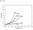
- the test conditions and results are shown in Table 3 and FIG. 8 .
- an approximate curve is shown as a dotted line portion following a broken line portion which is a measured value.
- TMP 3.0 MPa arrival time in Comparative Examples 4 and 5 in Table 3 is a predicted value calculated from the approximate curve.
- cross-flow filtration is performed by using a monolithic ceramic membrane filters including a slit and having a membrane pore size of 0.6 ⁇ m or more and 0.9 ⁇ m or less, and adding silica gel having a drying loss of 40% or more as a stabilizer to the fermented liquid, so that the rapid increase in transmembrane pressure is suppressed to enable a long-term filtration operation.
Landscapes
- Chemical & Material Sciences (AREA)
- Chemical Kinetics & Catalysis (AREA)
- Organic Chemistry (AREA)
- Inorganic Chemistry (AREA)
- Engineering & Computer Science (AREA)
- Food Science & Technology (AREA)
- Life Sciences & Earth Sciences (AREA)
- Biochemistry (AREA)
- Bioinformatics & Cheminformatics (AREA)
- General Engineering & Computer Science (AREA)
- General Health & Medical Sciences (AREA)
- Genetics & Genomics (AREA)
- Health & Medical Sciences (AREA)
- Wood Science & Technology (AREA)
- Zoology (AREA)
- Separation Using Semi-Permeable Membranes (AREA)
- Distillation Of Fermentation Liquor, Processing Of Alcohols, Vinegar And Beer (AREA)
Abstract
Description
- The present invention relates to a method of producing a fermented malt beverage and a method of filtering a fermented liquid.
- Fermented malt beverages such as beer and happoushu that use malt as a raw material are produced by adding yeast to a raw material liquid, fermenting the mixture, and then removing the yeast in a filtration step. In this filtration step, silica gel, polyvinylpolypyrrolidone (PVPP) or the like is generally used as a stabilizer in order to adsorb and remove causative substances of turbidity. As a filtration method, diatomaceous earth filtration has been conventionally used. However, in recent years, cross-flow filtration, which can suppress loss when switching varieties, generation of waste, etc. and is easy to handle, has come to be used. In the cross-flow filtration of fermented malt beverages, a polymer membrane filter is usually used. For example,
Japanese Patent Laid-open Publication No. S62(1987)-3287 - When the cross-flow filtration is applied to the production of fermented malt beverages such as beer, the time to continue the cross-flow filtration depends on a transmembrane pressure (TMP). If the transmembrane pressure becomes too high, load on a pump increases, so that filtration cannot be continued. Thus, in order to secure a practical filtration time, it is necessary to suppress the increase in the transmembrane pressure.
- Therefore, an object of the present invention is to provide a method of producing a fermented malt beverage, which includes a cross-flow filtration step using a ceramic membrane filter, suppresses a rapid increase in transmembrane pressure, and enables a long-term filtration operation.
- Specific means for solving the above-described object are as follows, and the present invention includes the following aspects.
- The first aspect is a method of producing a fermented malt beverage, which comprises cross-flow filtering a fermented liquid containing malt as a raw material. In this production method, the cross-flow filtration is performed through a monolithic ceramic membrane filter disposed apart from a flow path of the fermented liquid, including a slit having an opening in its side surface, and having a membrane pore size of 0.6 µm or more and 0.9 µm or less, and the fermented liquid contains silica gel having a drying loss of 40% or more.
- In one aspect, in the cross-flow filtration, a permeation flux may be 30 L/m2/h or more. In one aspect, the cross-flow filtration may be performed with a transmembrane pressure of 0.6 MPa or less. In one aspect, the cross-flow filtration may include increasing the transmembrane pressure to 0.3 MPa or more. In one aspect, the cross-flow filtration may be performed continuously for 3 hours or more using the same monolithic ceramic membrane filter. In one aspect, in the cross-flow filtration, a log reduction value LRV may be 5 or more relative to Lactobacillus brevis. In one aspect, the production method may not comprise at least one of a disinfection treatment and a sterilization treatment of the fermented liquid other than the cross-flow filtration. In one aspect, the production method may not comprise filtration of the fermented liquid other than the cross-flow filtration. In one aspect, the production method may not comprise a heat sterilization step of the fermented liquid. In one aspect, in the production method, the log reduction value LRV may be 5 or more relative to Lactobacillus brevis. In one embodiment, the cross-flow filtration may be performed through two or more monolithic ceramic membrane filters connected in parallel via a flow path. In one embodiment, the cross-flow filtration may be performed at a temperature of the fermented liquid of -2°C or higher and 3°C or lower.
- The second aspect is a method of filtering a fermented liquid, which includes cross-flow filtering the fermented liquid containing malt as a raw material. In this filtration method, the cross-flow filtration is performed through a monolithic ceramic membrane filter disposed apart from a flow path of the fermented liquid, including a slit having an opening in its side surface, and having a membrane pore size of 0.6 µm or more and 0.9 µm or less, and the fermented liquid contains silica gel having a drying loss of 40% or more.
- In one aspect, the cross-flow filtration is continuously performed by sequentially switching two or more monolithic ceramic membrane filters switchably connected to the flow path of the fermented liquid, and includes allowing the fermented liquid to permeate through at least one of the monolithic ceramic membrane filters and performing clean-in-place cleaning of at least one other of the monolithic ceramic membrane filters, and switching the flow path of the fermented liquid to allow the fermented liquid to permeate through the monolithic ceramic membrane filter after the clean-in-place cleaning and performing clean-in-place cleaning of the monolithic ceramic membrane filter through which the fermented liquid has permeated, and a time during which the fermented liquid is permeated may be longer than a time required for the clean-in-place cleaning.
- According to the present invention, it is possible to provide a method of producing a fermented malt beverage, which includes a cross-flow filtration step using a ceramic membrane filter, suppresses a rapid increase in transmembrane pressure, and enables a long-term filtration operation.
-
-
FIG. 1 is a schematic view showing a configuration of a general monolithic ceramic membrane filter. -
FIG. 2 is a schematic view showing a structure of the monolithic ceramic membrane filter provided with a slit. -
FIG. 3 is a schematic view showing an example of a configuration of a cross-flow filtration apparatus. -
FIG. 4 is a schematic view showing another example of the configuration of the cross-flow filtration apparatus. -
FIG. 5 is a schematic view for explaining a filtration method using a plurality of filters. -
FIG. 6 is a schematic view for explaining the filtration method using the plurality of filters. -
FIG. 7 is a schematic view showing a structure of the monolithic ceramic membrane filter provided with the slit, which has been used in Examples. -
FIG. 8 is a graph showing a relationship between a transmembrane pressure and a filtration time in Examples and Comparative Examples. -
FIG. 9 is a graph showing a relationship between the transmembrane pressure and the filtration time in Comparative Example and Reference Examples. -
FIG. 10 is a graph showing a relationship between the transmembrane pressure and the filtration time in Comparative Examples and Reference Examples. - In the present specification, in addition to an independent step, the term "step" also refers to a step that achieves an intended object of the step even when the step cannot be clearly distinguished from other steps. Numeric ranges indicated by "to" are ranges that include the minimum and maximum values each stated before and after the "to." In addition, in a case where a plurality of substances corresponding to each of the components in the composition are present, the content of each component in the composition, unless otherwise noted, is taken to mean the total amount of these substances present in the composition. Hereinafter, an embodiment of the present invention will be described in detail. However, the following embodiment exemplifies a method of producing a fermented malt beverage for embodying the technical idea of the present invention, and the present invention is not limited to the method of producing a fermented malt beverage, and the like shown below.
- The method of producing a fermented malt beverage comprises a filtration step of cross-flow filtering a fermented liquid containing malt as a raw material. The cross-flow filtration is performed through a monolithic ceramic membrane filter having a membrane pore size of 0.6 µm or more and 0.9 µm or less. The monolithic ceramic membrane filter is disposed apart from a flow path of the fermented liquid and includes a slit having an opening in its side surface. The fermented liquid used for cross-flow filtration contains silica gel having a drying loss of 40% or more. The production steps other than the filtration step, for example, a mashing step, a fermentation step, a packaging step, and the like are not particularly limited.
- The fermented liquid containing specific silica gel is permeated using a monolithic ceramic membrane filter having a pore size of the membrane within a specific range and including a slit through which a filtrate is removed, so that a rapid increase in transmembrane pressure is suppressed to enable a long-term filtration operation. Since yeast and microorganisms other than yeast are efficiently removed from the fermented liquid, it is not necessary to subject a filtrate to disinfection treatment, sterilization treatment, etc. like an additional filtration step, and the production step is simplified.
- The fermented malt beverage to be produced is a beverage produced, including a step of fermenting a raw material containing malt, and examples thereof include beers, happoushu, effervescent alcoholic beverages called a new genre, and refreshing drinks from which alcohol is removed from these beverages.
- Here, the beer may be beer defined by the Japanese Liquor Tax Act (Act No. 59 of 2018), the Japanese Liquor Tax Act Enforcement Order (Cabinet Order No. 136 of 2018), and the Ordinance for Enforcement of the Japanese Liquor Tax Act (Ordinance of the Ministry of Finance No. 19 of 2018), is not limited to these beers, and includes beer as a general concept.
- The beer in the above laws refers to the following alcoholic beverages with an alcohol content of less than 20%.
- A) Alcoholic beverages fermented using malt, hops and water as raw materials.
- B) Alcoholic beverages fermented using malt, hops, water, wheat and other products specified by government ordinance as raw materials (the alcoholic beverages are limited to those that have a malt weight of 50% or more of a total weight of raw materials other than hops and water, and in which a total weight of products specified by government ordinance in the raw materials does not exceed 5% of the weight of malt).
- C) Alcoholic beverages fermented by adding hops or products specified by government ordinance to the alcoholic beverages listed in A and B (the alcoholic beverages are limited to those that have a weight of 50% or more of a total weight of raw materials other than hops and water, and in which a total weight of products specified by government ordinance in the raw materials does not exceed 5% of the weight of malt).
- Happoushu includes alcoholic beverages, using malt or wheat as part of raw materials, other than beer and beer-like effervescent beverages, and the new genre is a product obtained by adding spirits to happoushu.
- The fermented liquid is a liquid obtained by alcohol-fermenting a raw material liquid containing sugar with yeast. The fermented liquid contains yeast, protein, polyphenols, etc., and may unintentionally contain microorganisms other than yeast. Lactic acid bacteria and the like can be considered as microorganisms that can be contained in addition to yeast. At least malt is used as a raw material for preparation of the raw material liquid When a plant-derived protein such as soybean protein is used as a raw material, filterability may deteriorate if a use ratio of dark-colored malt roasted at 100°C or higher is high. The fermented liquid may be prepared by fermenting a raw material liquid having a desired configuration with yeast by a commonly used method.
- Silica gel having a drying loss of 40% or more is added to the fermented liquid obtained by fermenting the raw material liquid by a conventional method. The fermented liquid is then subjected to the filtration step, and at least a portion of at least one substance selected from the group consisting of yeast, other microorganisms other than yeast, proteins, polyphenols and the like is removed by cross-flow filtration using the monolithic ceramic membrane filter including a slit.
- The fermented liquid subjected to the filtration step contains silica gel having a drying loss of 40% or more, preferably a drying loss of 50% or more. Silica gel is contained as a stabilizer, for example, in the fermented liquid. From the fermented liquid containing silica gel, proteins and the like that cause turbidity are adsorbed/removed from the fermented liquid by the filtration step. Since the fermented liquid contains silica gel having a drying loss of 40% or more and a high water content, the rapid increase in transmembrane pressure is suppressed in the filtration step.
- The drying loss of silica gel is a value measured in accordance with ISO 787-2: 1981 (JIS K 5101-15-1: 2004) and expressed as a mass fraction (%) by the following formula when the silica gel is dried at 105°C for 2 hours.

- Here, m0: mass of sample (g), and m1: mass of sample after drying (g).
- Commercially available silica gel may be used. Examples of silica gel having a drying loss of 40% or more include BRITESORB (registered trademark) manufactured by PQ Corporation and DARACLAR (registered trademark) manufactured by Grace WR & Co. As the silica gel, for example, it is possible to use silica gel having a volume-based 50% particle diameter (median diameter; d50) of 15 µm or more and 45 µm or less and a drying loss of 40% or more and 70% or less.
- It is preferable that in the silica gel used, a number-based 10% particle diameter (d10) is larger than the pore size of the ceramic membrane filter. As a result, clogging of the membrane filter is more effectively suppressed, and the rapid increase in transmembrane pressure is further suppressed in the filtration step. The number-based 10% particle diameter (d10) of silica gel is, for example, 1.0 µm or more, preferably 2.0 µm or more, and, for example, 5.0 µm or less.
- The number-based 50% particle diameter of silica gel is, for example, 3.0 µm or more, preferably 5.0 µm or more, and, for example, 15.0 µm or less, preferably 10.0 µm or less. The volume-based 50% particle diameter of silica gel is, for example, 4.0 µm or more, preferably 15.0 µm or more, and, for example, 45.0 µm or less, preferably 35.0 µm or less. When the number-based or volume-based 50% particle diameter is in the above range, the rapid increase in transmembrane pressure is further suppressed in the filtration step.
- Any percent particle diameter of silica gel may be measured using a commercially available particle diameter distribution measuring device, particle counter, or the like in accordance with ISO 13320: 2009 (JIS Z 8825: 2013).
- A specific surface area of silica gel is, for example, 300 m2/g or more, preferably 500 m2/g or more, and for example 1000 m2/g or less, preferably 850 m2/g or less. When the specific surface area of silica gel is in the above range, proteins are sufficiently removed in the filtration step.
- A content of silica gel is, for example, preferably 100 ppm or more, more preferably 200 ppm or more, still more preferably 300 ppm or more, based on the fermented liquid. The silica gel content is, for example, preferably 2000 ppm or less, more preferably 1200 ppm or less, and still more preferably 1000 ppm or less. Here, the silica gel content of 1 ppm corresponds to 1 mg/L. When the silica gel content is equal to or more than the above lower limit value, proteins that cause turbidity can be sufficiently adsorbed/removed. When the silica gel content is equal to or less than the above upper limit value, the deterioration of the filterability is suppressed, and foam retention of the fermented malt beverage is well maintained.
- In the present embodiment, silica hydrogel having a relatively large drying loss (moisture content) of 40% or more is used as silica gel. In addition to this, silica gel includes silica xerogel having a relatively small drying loss (moisture content). In Japan, it is common to use easily available silica xerogel having a drying loss of 10% or less in the method of producing a fermented malt beverage. As the silica xerogel, for example, SYLOPUTE (registered trademark) manufactured by Fuji Silysia Chemical Ltd., CARPLEX (registered trademark) manufactured by Evonik Industries Ag, etc. are commercially available.
- However, in the cross-flow filtration using a ceramic membrane filter, when silica xerogel as a stabilizer and a main component is added to the fermented liquid, the increase in transmembrane pressure (TMP) becomes extremely fast, which may make long-term filtration operation difficult. On the other hand, when silica hydrogel having a drying loss of 40% or more is added as a main component, such a rapid increase in transmembrane pressure is sufficiently suppressed. The transmembrane pressure is expressed by the following formula, and when a plurality of ceramic membrane filters are used, the transmembrane pressure as the entire filtration apparatus is taken into consideration.

- The fermented liquid may contain silica xerogel as long as the effects of the present invention are not impaired. When the fermented liquid contains silica xerogel, the content thereof is, for example, 500 ppm or less, preferably 300 ppm or less, more preferably 150 ppm or less, and still more preferably less than 1 ppm. That is, it is preferable that the fermented liquid does not substantially contain silica xerogel.
- The fermented liquid may contain polyvinylpolypyrrolidone (PVPP) as a stabilizer for adsorbing/removing turbidity-causing substances. As PVPP, Divergan (registered trademark) manufactured by BASF, Polyclar (registered trademark) manufactured by Ashland, etc. are commercially available. When the fermented liquid contains PVPP, the content thereof is, for example, 300 ppm or less, preferably 200 ppm or less, more preferably 150 ppm or less, and still more preferably less than 1 ppm. That is, it is preferable that the fermented liquid does not substantially contain polyvinylpolypyrrolidone.
- In the present embodiment, by using silica hydrogel as a stabilizer, for example, even when the transmembrane pressure rises to 0.3 MPa or more, cleaning recoverability of the ceramic membrane filter is well maintained, and the permeation flux can be sufficiently and easily restored by cleaning with a cleaning agent. Although the ceramic membrane filter itself has a pressure resistance of 1 MPa or more, considering load on a pump, a supply pressure of pneumatic instrumentation, equipment maintenance, etc., the transmembrane pressure during the filtration step is, for example, less than 1 MPa, preferably 0.6 MPa or less, and more preferably 0.5 MPa or less.
- Since silica hydrogel has lower adsorptivity to polyphenols than that of PVPP, it is considered that influence on a flavor of fermented malt beverage is less than that when PVPP is used.
- In the method of producing a fermented malt beverage, a monolithic ceramic membrane filter provided with a slit (hereinafter, also simply referred to as "ceramic membrane filter") is used. In general, the ceramic membrane filter is superior in heat resistance, corrosion resistance, and durability to a polymer membrane filter. Since it is possible to perform chemical cleaning, back pressure cleaning, and regeneration by baking, the labor and cost of replacing the membrane filter can be reduced. Since the ceramic membrane filter has high strength, cross-flow filtration at a high filtration pressure or circulation flow velocity is possible, and, in addition, the ceramic membrane filter has such a characteristic that a pore size distribution is sharp and separation accuracy is high.
- The monolithic ceramic membrane filter has a cylindrical shape or a prismatic shape, and is provided with a stock solution channel penetrating between two end surfaces (for example, bottom surface and top surface) orthogonal to a stretching direction. A stock solution to be filtered is filtered by a membrane layer provided surrounding the stock solution channel while flowing through the stock solution channel and passes through a substrate material layer, and a filtered solution flows out to a permeation side. A cross-sectional shape of the stock solution channel may be any of a circular shape, an elliptical diameter, an oval shape, a polygonal shape, and the like.
- The ceramic membrane filter is configured by, for example, providing a membrane layer having a desired pore size (average pore diameter) on a porous substrate material layer. An intermediate layer may be provided between the substrate material layer and the membrane layer, if necessary. By providing the underlying intermediate layer, it is possible to suppress outflow of ceramic particles constituting the membrane layer, for example, even when the pore size of the membrane layer is as fine as 0.5 µm or less.
- The ceramic membrane filter used in the present embodiment is provided with a slit (hereinafter, also referred to as a liquid collecting slit). The slit is provided in the substrate material layer so as not to intersect the stock solution channel and has an opening on a surface of the ceramic membrane filter. The opening of the slit may be provided on a side surface of the ceramic membrane filter, for example, and the slit may be provided so as to penetrate between the side surfaces. A cross-sectional shape of the slit may be, for example, a rectangular shape, and may be a substantially circular shape, an elliptical diameter, an oval shape, a polygonal shape, or the like. The slit may be provided, for example, in the substrate material layer so as to be substantially parallel to the stock solution channel and may be connected to at least one liquid collection channel having no opening on its end surface. A cross-sectional shape of the liquid collection channel may be any of a circular shape, an elliptical diameter, an oval shape, a polygonal shape, and the like. By providing the slit, a maximum value of a distance from the stock solution channel to a surface on the permeation side can be reduced, and a surface area on the permeation side can be increased, so that the permeation flux can be improved.
- For the ceramic membrane filter having the slit, see, for example,
US Pat. No. 4,781,831 ,WO 2013/147271 and the like. -
FIG. 1 is a schematic view showing a configuration of a general monolithicceramic membrane filter 100. A stock solution to be filtered enters an inside of eachstock solution channel 10 which is a flow path, and is filtered by seeping out from the inside of thestock solution channel 10 through amembrane layer 20 and asubstrate material layer 30. In the general monolithicceramic membrane filter 100 shown inFIG. 1 , no slit is provided in thesubstrate material layer 30. -
FIG. 2 is a schematic view showing an example of a configuration of a monolithicceramic membrane filter 200 having a slit according to the present embodiment.FIG. 2 is a partially reorganized drawing taken from the website of METAWATER Co., Ltd. (http://www.metawater.co.jp/news/2016/11/20161125-1.html). In the monolithicceramic membrane filter 200, a plurality of thestock solution channels 10 are provided as through holes penetrating in a length direction of the monolithicceramic membrane filter 200 and having a substantially circular cross section. The plurality of thestock solution channels 10 are arranged substantially parallel to each other in a direction substantially orthogonal to the length direction. In the monolithicceramic membrane filter 200, in thesubstrate material layer 30, aliquid collection channel 40 for collecting a filtrate is formed as a columnar hole having a substantially circular cross section without having an opening on its end surface. A plurality of theliquid collection channels 40 are provided so as not to intersect thestock solution channel 10 and substantially parallel to thestock solution channel 10. That is, theliquid collection channel 40 is provided apart from thestock solution channel 10 by thesubstrate material layer 30. A liquid collecting slit 50 is connected to the plurality ofliquid collection channels 40 arranged substantially parallel to a stretching direction of the liquid collecting slit 50, and is provided with anopening 55 on a side surface of the monolithicceramic membrane filter 200. InFIG. 2 , the liquid collecting slit 50 is disposed so as to penetrate thesubstrate material layer 30 from one side surface side to the other side surface side of the monolithicceramic membrane filter 200. InFIG. 2 , the six liquid collecting slits 50 are arranged; however, the number of liquid collecting slits arranged may be, for example, 2 to 8. - The monolithic
ceramic membrane filter 200 has, in thesubstrate material layer 30, the liquid collecting slit 50 connected to theliquid collection channel 40 and having the opening 55 on the side surface. As a result, a maximum value of a distance from the surface of themembrane layer 20 to the surface on the permeation side is reduced, the surface area on the permeation side increases, and a high permeation flux can be achieved. - The permeation flux of the monolithic ceramic membrane filter in the filtration step is, for example, 30 L/m2/h or more, preferably 40 L/m2/h or more, more preferably 50 L/m2/h or more, and still more preferably more than 50 L/m2/h. When the permeation flux is equal to or more than the above lower limit value, it is possible to reduce a membrane area of the monolithic ceramic membrane filter and the number of monolithic ceramic membrane filters used with respect to a target permeation flow rate (L/h).
- On the other hand, the permeation flux is, for example, 100 L/m2/h or less, preferably 80 L/m2/h or less, and more preferably 70 L/m2/h or less. When the permeation flux is equal to or less than the upper limit value, a rate of increase in transmembrane pressure is further suppressed, and the load on the pump installed on a primary side of the ceramic membrane filter due to the increase in transmembrane pressure is further reduced. As a result, time until an upper limit of a pump discharge pressure is reached is further extended, and a time during which continuous filtration can be performed using the same ceramic membrane filter is longer.
- The pore size of the ceramic membrane filter is, for example, 0.6 µm or more and 0.9 µm or less, and preferably 0.6 µm or more and 0.8 µm or less. When the pore size of the ceramic membrane filter is 0.6 µm or more, the rate of increase in transmembrane pressure can be effectively suppressed, and continuous operation of the filtration step for a long time becomes possible. When the pore size of the ceramic membrane filter is equal to or less than the above upper limit value, sterilization performance of the ceramic membrane filter is sufficiently maintained, and it is not necessary to carry out disinfection treatment, sterilization treatment, etc. of the fermented liquid other than cross-flow filtration. The sterilization performance of the ceramic membrane filter will be described later.
- The pore size of the ceramic membrane filter may be measured using a commercially available porosimeter of mercury intrusion type, for example, in accordance with JIS R 1655: 2003 "Test methods for pore size distribution of fine ceramic green body by mercury porosimetry". In the present specification, a peak value corresponding to the membrane layer read from a frequency distribution curve for a pore size that is obtained from test results by a test method specified in JIS R 1655: 2003 is defined as the pore size.
- When a fermented liquid containing malt as a raw material is cross-flow filtered using the ceramic membrane filter, if the fermented liquid contains silica xerogel having a small drying loss (moisture content) as the main component of the stabilizer, the rate of increase in transmembrane pressure may increase. In particular, . when the silica xerogel contains almost no particles having a particle diameter smaller than the pore size of the ceramic membrane filter, the rate of increase in transmembrane pressure may increase, for example even when the number-based 10% particle diameter (d10) is larger than the pore size.
- The sterilization performance of the ceramic membrane filter may be evaluated by a log reduction value (LRV) obtained by a bacterial challenge test. The log reduction value of the ceramic membrane filter is, for example, 5 or more, preferably 6 or more, more preferably 7 or more, and still more preferably 9 or more. When the log reduction value of the filtration step using the ceramic membrane filter is 5 or more, the log reduction value as the entire production step can be easily set to 5 or more. As a result, in the production method in the present embodiment, it is less necessary to carry out sterilization treatment, disinfection treatment, etc. of the fermented liquid in addition to the cross-flow filtration. The added sterilization treatment, disinfection treatment, etc. of the fermented liquid are generally carried out by, for example, an additional filtration treatment, heat sterilization treatment, etc.
- In general, when a fermented malt beverage is produced without a heat sterilization step such as pastorization, it is desirable to secure a log reduction value (LRV) of 5 or more in the entire production step due to food hygiene reasons and need to capture microorganisms that affect quality. However, with conventional diatomaceous earth filtration and cross-flow filtration using a polymer membrane filter, it is difficult to achieve a log reduction value of 5 or more by a single step, and it has been necessary to provide disinfection treatment, sterilization treatment, and the like, as an additional filtration step to these cross-flow filtration steps. However, by using a ceramic membrane filter having a specific pore size, it is easily achieved that the log reduction value is 5 or more.
- In the present specification, the bacterial challenge test is evaluated by the sterilization performance to microorganism which is mixed into a fermented malt beverage such as beer to cause turbidity, for example, Lactobacillus brevis, a lactic acid bacterium belonging to genus Lactobacillus, and is a typical beer-spoilage microorganism.
- Specifically, the bacterial challenge test may be carried out by the following method. A test bacterium (Lactobacillus brevis NBRC 107147) is inoculated on MRS agar medium (Lactobacilli MRS Agar (Difco)), cultured at 30°C for 3 days, and the obtained microbial cell body is inoculated on MRS liquid medium (Lactobacilli MRS Broth (Difco)) and cultured at 30°C for 2 days. After centrifuging this culturing solution, the obtained microbial cell body is suspended in sterilized purified water so that the number of bacteria per 1 mL is about 1010 to obtain a bacterial solution. The bacterial solution is added to and mixed with 40 L of pure water so that the number of bacteria per 1 mL is about 107, to prepare a test solution. A 1000 mL of the test solution is made to pass through a sample under conditions of 0.10, 0.15 and 0.20 MPa, to collect the passing water. The number of live bacterial cells (the number of test bacteria) of the test solution before passing through the sample is calculated by converting the number of live bacterial cells per 1 mL, measured by a flat plate smear culture method using MRS agar medium, into the number per 1000 mL. The number of live bacterial cells (the number of leaked bacteria) of the passing water is measured by a membrane filter method (30°C, culture for 3 days).
- From the above test results, LRV is calculated by the following formula.

- Here, A: the number of test bacteria and B: the number of leaked bacteria. If the number of leaked bacteria is 0, 1 is used for B, and the evaluation is made as LRV ≥ log10A.
- The material of the monolithic ceramic membrane filter used in the cross-flow filtration step is not particularly limited, and it is common to use high-purity alumina (Al2O3) for the substrate material layer, the intermediate layer, and the membrane layer.
- The membrane area of the ceramic membrane filter, the surface area on the permeation side, the maximum value of the distance from the membrane surface to the surface on the permeation side, and the like may be selected according to a target filtration flow rate (L/h) and the like. For example, when a monolithic membrane filter having a diameter of 60 mm and a length of about 1100 mm is used, specifically, the membrane area of the ceramic membrane filter is, for example, 0.8 m2 or more and 4.0 m2 or less, and preferably 1.5 m2 or more and 3.0 m2 or less The surface area on the permeation side is, for example, 0.22 m2 or more and 0.70 m2 or less, and preferably 0.40 m2 or more and 0.55 m2 or less. A ratio of the maximum value of the distance from the membrane surface to the surface on the permeation side to an outer diameter of the monolithic ceramic membrane filter is, for example, 0.06 or more and 0.31 or less, and preferably 0.12 or more and 0.23 or less. In addition, a ratio of the surface area on the permeation side to the membrane area of the ceramic membrane filter is, for example, 0.09 or more and 0.30 or less, and preferably 0.15 or more and 0.25 or less.
- The cross-flow filtration in the filtration step may be carried out using a plurality of monolithic ceramic filters. When the plurality of monolithic ceramic filters are used, the plurality of monolithic ceramic filters may be connected in parallel or in series via a flow path. The plurality of monolithic ceramic filters preferably include at least monolithic ceramic filters connected in parallel. As a result, the entire membrane layer of the ceramic membrane filter can be used more uniformly, and the rate of increase in transmembrane pressure can be suppressed more effectively. In addition, a desired permeation flow rate can be easily achieved.
- An arrangement example of a plurality of monolithic ceramic membrane filters used for cross-flow filtration of the fermented liquid will be described with reference to
FIGS. 3 and 4 . InFIG. 3 , all the four monolithic ceramic membrane filters 200 are arranged in a parallel relationship, and four flow paths branched from one flow path are connected to each of the monolithic ceramic membrane filters 200. InFIG. 4 , two units consisting of the two monolithic ceramic membrane filters 200 arranged in parallel are arranged in series. In each unit, the two monolithic ceramic membrane filters 200 are arranged in parallel, and two flow paths branched from one flow path are connected to each of the monolithic ceramic membrane filters 200. The monolithic ceramic membrane filters 200 are arranged in series as a unit, and one flow path is connected to the inflow side and the outflow side of each unit. - When a plurality of monolithic ceramic filters are used in the filtration step, cross-flow filtration may be continuously performed by sequentially switching two or more monolithic ceramic membrane filters switchably connected to the flow path of the fermented liquid. In this case, the filtration step includes allowing the fermented liquid to permeate through at least one monolithic ceramic membrane filter and performing clean-in-place cleaning of at least one other monolithic ceramic membrane filter, and switching the flow path of the fermented liquid to allow the fermented liquid to permeate through the monolithic ceramic membrane filter after the clean-in-place cleaning and performing clean-in-place cleaning of the monolithic ceramic membrane filter through which the fermented liquid has permeated. In the present embodiment, it is preferable that a time required for the permeation of the fermented liquid is longer than a time required for the clean-in-place cleaning.
- An example of the filtration step performed by sequentially switching a plurality of monolithic ceramic membrane filters will be described with reference to
FIGS. 5 and 6 . InFIG. 5 , the fermented liquid containing silica gel flows along the flow path shown by the solid line and is cross-flow filtered by afiltration device 220 including the monolithic ceramic membrane filter. During filtration of the fermented liquid by thefiltration device 220, a cleaning liquid and water flow along the flow path shown by the broken line, and afiltration device 210 including the monolithic ceramic membrane filter is subjected to clean-in-place (CIP) cleaning. Next, inFIG. 6 , the fermented liquid containing silica gel is supplied to thefiltration device 210 subjected to clean-in-place cleaning along the flow path shown by the solid line, and the fermented liquid is cross-flow filtered. On the other hand, in thefiltration device 220 used for the cross-flow filtration of the fermented liquid, the cleaning liquid and water flow along the flow path shown by the broken line to perform clean-in-place cleaning. By sequentially switching between the state ofFIG. 5 and the state ofFIG. 6 by a flow path switching device, the fermented liquid can be continuously filtered. Thefiltration devices FIG. 3 or FIG. 4 , for example. - The clean-in-place cleaning is performed by, for example, supplying a
first cleaning agent 410, asecond cleaning agent 420, athird cleaning agent 430, andwater 440 to the flow path, and allowing at least one of the cleaning agent and water to permeate through thefiltration devices heating device 450. The cleaning agent, water, etc. used for clean-in-place cleaning are discharged from adrainage section 460 at any time. - In the present embodiment, it is preferable that a time during which the fermented liquid can be continuously filtered by one filtration device including the ceramic membrane filter is longer than a time required for the clean-in-place cleaning of the ceramic membrane filter. This enables continuous filtration without stopping the supply of the fermented liquid. Generally, the time required for the clean-in-place cleaning of the ceramic membrane filter is about 2 to 3 hours. Therefore, if a time during which the fermented liquid can be continuously filtered without cleaning the ceramic membrane filter is, for example, 3 hours or more, the fermented liquid can be continuously filtered. The time during which the fermented liquid can be continuously filtered is preferably 5 hours or more, which is about the same as cross-flow filtration using a filtration device including a polymer membrane filter, and the time is more preferably 6 hours or more.
- In the filtration step, the temperature of the fermented liquid at the time of passage through the ceramic membrane filter is, for example, -2°C or higher and 3°C or lower, and preferably -2°C or higher and lower than 2°C. By forcibly expressing chill haze at such a temperature, a turbid substance can be more efficiently removed by cross-flow filtration. The temperature of the fermented liquid may be adjusted, for example, by a cooler 310 as shown in
FIGS. 3 and 4 . - In general, the faster a circulation linear speed of the fermented liquid in the filtration step, the more the increase in transmembrane pressure can be suppressed; however, considering the load on the pump and the like, the circulation linear speed is, for example, 1 m/s or more and 3 m/s or less.
- Hereinafter, the present invention will be specifically described based on examples. However, the present invention is not limited to these examples.
- As a monolithic ceramic membrane filter, a ceramic membrane filter A having a structure provided with four liquid collecting slits as shown in a schematic view in
FIG. 7 was prepared.FIG. 7A is a schematic cross-sectional view of aceramic membrane filter 230 taken along the line a-a inFIG. 7B, and FIG. 7B is a partially see-through schematic plan view seen from a side surface. As shown inFIG. 7A , in the cross section of theceramic membrane filter 230, thesubstrate material layer 30 is provided with the stock solution channel 10 (only a part thereof is shown). The plurality of liquid collection channels 40 (only a part thereof is shown) are provided in parallel with thestock solution channel 10, and the four liquid collecting slits 50 connected to the plurality ofliquid collection channels 40 and penetrating between the side surfaces are provided. As shown inFIG. 7B , theceramic membrane filter 230 is provided with theliquid collection channel 40 having no opening on a plurality of end surfaces in the stretching direction. On the side surface of theceramic membrane filter 230,openings 55 are provided at eight locations corresponding to the four liquid collecting slits 50. An outline of the specifications of the ceramic membrane filter A is shown below. -
- Ceramic membrane filter A
- Material (membrane layer, substrate material): Alumina (Al2O3)
- Pore size: 0.7 µm, 0.5 µm or 1.0 µm
- External shape: ϕ60 mm × length 1100 mm
- Membrane area: 2.3 m2
- The number of slits: four slits, openings at eight locations
- Surface area on permeation side: 0.51 m2
- Distance from membrane surface to permeation side: up to 11 mm
- A ceramic membrane filter B having the same configuration as the above was prepared except that no slit was provided for comparison.
- Ceramic membrane filter B
- Pore size: 0.7 µm
- Surface area on permeation side: 0.22 m2
- Distance from membrane surface to permeation side: up to 32mm
- The pore size of the ceramic membrane filter was measured under the following conditions based on JIS R 1655: 2003 "Test methods for pore size distribution of fine ceramic green body by mercury porosimetry".
[Table 1] Material and morphology of sample Al2O3 Product cut out from a ceramic membrane filter (including membrane layer and base material)) Sample mass about 3g Sample pretreatment Drying treatment Equipment used Commercially available mercury press-fit porosimeter Mercury used Reagent grade Physical characteristics of mercury used in the calculation Contact angle 130° Surface tension 485dynes/cm Measurement mode In the process of continuously changing the pressure, the pressure and the amount of mercury injection were measured when the pressure change or the change in the amount of mercury injection exceeded a certain value. Blank correction None - In the frequency distribution curve for a pore size, since a plurality of peaks were obtained depending on the membrane layer and the substrate material, a peak value corresponding to the membrane layer was defined as the pore size.
- A mixture of 800 kg of malt and 2000 L of water was held at 50°C for 30 minutes to decompose protein. Then, 1200 L of water was added, and the mixture was held at 64°C for 20 minutes to saccharify a malt-derived component to obtain wort. After filtering the wort, hops were added and boiled for 90 minutes. After the boiling treatment, concentration adjusting hot water was added to obtain 5000 L of fermentation raw material solution with 12° P To the obtained fermentation raw material solution, 30 kg of bottom fermentation yeast in terms of dry weight was added, and the mixture was fermented at 12°C for 7 days. Then, the mixture was aged at 10°C for 10 days, then further cooled to 0°C, and stored for 7 days to prepare a beer fermented liquid. The number of yeasts in the beer fermented liquid was 3 × 10⁶ cells/ml.
- The following silica hydrogel, silica xerogel and PVPP were provided as stabilizers.
-
- Drying loss: 66%
- Volume-based 50% particle diameter (median diameter; d50): 19.0 µm
- Number-based 50% particle diameter (median diameter; d50): 5.2 µm
- Number-based 10% particle diameter (d10): 2.5 µm
- Specific surface area (ISO 9277): 763 m2/g
-
- Drying loss: 4.2%
- Volume-based 50% particle diameter (median diameter; d50): 12.8 µm
- Number-based 50% particle diameter (median diameter; d50): 3.8 µm
- Number-based 10% particle diameter (d10): 2.1 µm
- Specific surface area (ISO 9277): 575 m/g
-
- Drying loss: less than 6.0%
- 200 mesh pass rate: 90% or more
- 400 mesh pass rate: 45% or more and less than 90%
- An amount of water permeation of the ceramic membrane filter before cross-flow filtration under each condition and the amount of water permeation after CIP cleaning under the following conditions after cross-flow filtration were measured, and a rate of change thereof was calculated to evaluate the cleaning recoverability.
-
- (1) Water/normal temperature
- (2) Caustic soda (sodium hydroxide) 1%/80°C/30 minutes
- (3) Hot water/55°C
- (4) Hot water/35°C/caustic soda (sodium hydroxide) 1% and sodium hypochlorite 500 ppm
- (5) Hot water/35°C
- (6) Hot water/35°C/0.1% phosphoric acid
- (7) Water/normal temperature
- Water at room temperature was made to pass through a ceramic membrane filter for 300 seconds, and the amount of water permeation was determined by averaging the transmission line bundles every 10 seconds. The amount of water permeation fluctuated depending on the temperature at the time of measurement and the transmembrane pressure and therefore was converted to a value at 25°C under 1 bar. The following formula and a temperature correction value were used for conversion.

-
[Table 2] Real temperature (°C) Correction value Real temperature (°C) Correction value Real temperature (°C) Correction value Real temperature (°C) Correction value ∼1.4 1.934 10.5∼11.4 1.422 20.5∼21.4 1.099 30.5∼31.4 0.875 1.5∼2.4 1.870 11.5∼12.4 1.383 21.5∼22.4 1.073 31.5∼32.4 0.860 2.5∼3.4 1.808 12.5∼13.4 1.346 22.5∼23.4 1.048 32.5∼33.4 0.839 3.5∼4.4 1.751 13.5∼14.4 1.311 23.5~24.4 1.022 33.5∼34.4 0.822 4.5∼5.4 1.696 14.5∼15.4 1.278 24.5~25.4 1.000 34.5∼35.4 0.806 5.5∼6.4 1.645 15.5∼16.4 1.245 25.5∼26.4 0.977 35.5~36.4 0.799 6.5∼7.4 1.596 16.5∼17.4 1.214 26.5∼27.4 0.955 36.5∼37.4 0.773 7.5∼8.4 1.549 17.5∼18.4 1.184 27.5~28.4 0.934 37.5∼38.4 0.759 8.5∼9.4 1.505 18.5∼19.4 1.153 28.5∼29.4 0.913 38.5∼39.4 0.744 9.5∼10.4 1.463 19.5∼20.4 1.127 29.5~30.4 0.893 39.5~40.4 0.730 - The fermented malt beverage produced was stored at 50°C for 1 week and then stored at 0°C for 1 day, and the presence or absence of turbidity was visually confirmed.
- A filtration test of the fermented liquid was carried out under the test conditions shown below using a cross-flow filtration apparatus provided with four monolithic ceramic membrane filters as shown in
FIG. 3 or FIG. 4 . The test conditions and results are shown in Table 3 andFIG. 8 . In Comparative Examples 3, 4 and 5 inFIG. 8 , an approximate curve is shown as a dotted line portion following a broken line portion which is a measured value. TMP = 3.0 MPa arrival time in Comparative Examples 4 and 5 in Table 3 is a predicted value calculated from the approximate curve.[Table 3] Ceramic membrane filter Stabilizer Filtration conditions Cross-flow filtration test results Turbid stability Pore size [µm] Slit LRV Type Content ratio [ppm] Permeated flux [L/m2/h] Temperature [°C] Circulation line speed [m/s] Channel TMP= 0.10MPa Time of attainment [h] TMP= 0.30MPa Time of attainment [h] Rate of permiability [%] (attained TMP) Example 1 0.7 Yes ≥7 Hydrogel 500 50 -1.5 1.5 Parallel - - No turbidity Example 2 0.7 Yes ≧7 Hydrogel 500 75 -1.5 1.5 Parallel 2.5 5.4 ▼7.4% 0.33MPa) No turbidity Example 3 0.7 Yes ≥7 Hydrogel 1000 50 -1.5 1.5 Parallel - - - No turbidity Comparative example 1 0.7 No - None - 25 -1.5 1.5 Parallel 0.0 3.5 - Turbidity Comparative example 2 0.7 Yes ≧7 None - 50 -1.5 1.5 Parallel - - - Turbidity Comparative example 3 0.7 Yes ≧7 Xerogel 500 50 -1.5 1.5 Parallel 2.0 3.8 △4.0% (0.24MPa) No turbidity ▼13.5% (0.31MPa) Comparative example 4 0.7 Yes ≥7 Xerogel /PVPP 400 /100 50 -1.5 1.5 Parallel 2.2 3.9* - No turbidity Comparative example 5 0.5 Yes ≧7 Hydrogel 500 50 -1.5 1.5 Parallel 3.1 6.1* - No turbidity Comparative example 6 1.0 Yes <5 Hydrogel 500 50 -1.5 1.5 Parallel - - No turbidity - A filtration test of the fermented liquid was carried out in the same manner as above except that the test conditions shown below were used. The test conditions and results are shown in Table 4 and
FIG. 9 together with Comparative Example 3.[Table 4] Ceramic membrane filter Stabilizer Filtration conditions Cross-flow filtration test results Turbid stability Pore size [µm] Slit LRV Type Content ratio [ppm] Permeated flux [L/m2/h] Temperature [°C] Circulation line speed [m/s] Channel TMP= 0.10MPa Time of attainment [h] Rate of permiability [%] (attained TMP) Comparative example 3 0.7 Yes ≥7 Xerogel 500 50 -1.5 1.5 Parallel 2.0 - No turbidity Reference example 1 0.7 Yes ≧7 Xerogel 750 50 -1.5 1.5 Parallel 1.4 - No turbidity Reference example 2 0.7 Yes ≥7 Xerogel 750 50 2.0 1.5 Parallel 3.6 ▼1.9% (0.25MPa) Turbidity Reference example 3 0.7 Yes ≥7 Xerogel 750 50 -1.5 2.0 Parallel 2.6 No turbidity Reference example 4 0.7 Yes ≥7 Xerogel 750 50 -1.5 1.5 Parallel +serise 1.0 ▼14.2% (0.33MPa) No turbidity - A filtration test of the fermented liquid was carried out in the same manner as above except that the test conditions shown below were used. The test conditions and results are shown in Table 5 and
FIG. 10 together with Comparative Examples 2 and 3.[Table 5] Ceramic membrane filter Stabilizer Filtration conditions Cross-flow filtration test results Pore size [µm] Slit LRV Type Content ratio [ppm] Permeated flux [L/m2/h] Temperature [°C] Circulation line speed [m/s] Channel TMP= 0.10MPa Time of attainment [h] Comparative example 2 0.7 Yes ≥7 None - 50 -1.5 1.5 Parallel - Comparative example 3 0.7 Yes ≥7 Xerogel 500 50 -1.5 1.5 Parallel 2.0 Reference example 5 0.5 Yes ≧7 None - 50 -1.5 1.5 Parallel 2.7 Reference example 6 0.5 Yes ≥7 Xerogel 500 50 -1.5 1.5 Parallel 1.7 Reference example 7 1.0 Yes <5 None - 50 -1.5 1.5 Parallel - Reference example 8 1.0 Yes <5 Xerogel 500 50 -1.5 1.5 Parallel - - From the above, cross-flow filtration is performed by using a monolithic ceramic membrane filters including a slit and having a membrane pore size of 0.6 µm or more and 0.9 µm or less, and adding silica gel having a drying loss of 40% or more as a stabilizer to the fermented liquid, so that the rapid increase in transmembrane pressure is suppressed to enable a long-term filtration operation.
- Disclosure of
JP 2019-003781 A (filed on Jan. 11, 2019
Claims (14)
- A method of producing a fermented malt beverage, comprising performing cross-flow filteration of fermented liquid containing malt as a raw material,wherein the cross-flow filtration is performed through a monolithic ceramic membrane filter disposed apart from a flow path of the fermented liquid, including a slit having an opening in its side surface, and having a membrane pore size of 0.6 µm or more and 0.9 µm or less, andthe fermented liquid contains silica gel having a drying loss of 40% or more.
- The production method according to claim 1, wherein in the cross-flow filtration, a permeation flux is 30 L/m2/h or more.
- The production method according to claim 1 or 2, wherein the cross-flow filtration is performed with a transmembrane pressure of 0.6 MPa or less.
- The production method according to any one of claims 1 to 3, wherein the cross-flow filtration includes increasing the transmembrane pressure to 0.3 MPa or more.
- The production method according to any one of claims 1 to 4, wherein the cross-flow filtration is performed continuously for 3 hours or more using the same monolithic ceramic membrane filter.
- The production method according to any one of claims 1 to 5, wherein in the cross-flow filtration, a log reduction value LRV is 5 or more relative to Lactobacillus brevis.
- The production method according to any one of claims 1 to 6, which does not comprise at least one of a disinfection treatment and a sterilization treatment of the fermented liquid other than the cross-flow filtration.
- The production method according to any one of claims 1 to 7, which does not comprise filtration of the fermented liquid other than the cross-flow filtration.
- The production method according to any one of claims 1 to 8, which does not comprise a heat sterilization step of the fermented liquid.
- The production method according to any one of claims 1 to 9, wherein in the production method, the log reduction value LRV is 5 or more relative to Lactobacillus brevis.
- The production method according to any one of claims 1 to 10, wherein the cross-flow filtration is performed through two or more monolithic ceramic membrane filters connected in parallel via a flow path.
- The production method according to any one of claims 1 to 11, wherein the cross-flow filtration is performed at a temperature of the fermented liquid of -2°C or higher and 3°C or lower.
- A method of filtering a fermented liquid, comprising cross-flow filtering a fermented liquid containing malt as a raw material,wherein the cross-flow filtration is performed through a monolithic ceramic membrane filter disposed apart from a flow path of the fermented liquid, including a slit having an opening in its side surface, and having a membrane pore size of 0.6 µm or more and 0.9 µm or less, andthe fermented liquid contains silica gel having a drying loss of 40% or more.
- The filtration method according to claim 13, wherein the cross-flow filtration is continuously performed by sequentially switching two or more monolithic ceramic membrane filters switchably connected to the flow path of the fermented liquid, and includes allowing the fermented liquid to permeate through at least one of the monolithic ceramic membrane filters and performing clean-in-place cleaning of at least one other of the monolithic ceramic membrane filters, andswitching the flow path of the fermented liquid to allow the fermented liquid to permeate through the monolithic ceramic membrane filter after the clean-in-place cleaning and performing clean-in-place cleaning of the monolithic ceramic membrane filter through which the fermented liquid has permeated, anda time during which the fermented liquid is permeated is longer than a time required for the clean-in-place cleaning.
Applications Claiming Priority (2)
| Application Number | Priority Date | Filing Date | Title |
|---|---|---|---|
| JP2019003781A JP2020110089A (en) | 2019-01-11 | 2019-01-11 | Method for producing fermented malt beverage and method for filtering fermentation liquid |
| PCT/JP2020/000138 WO2020145258A1 (en) | 2019-01-11 | 2020-01-07 | Production method for fermented malt beverage and filtration method for fermented liquid |
Publications (3)
| Publication Number | Publication Date |
|---|---|
| EP3909670A1 true EP3909670A1 (en) | 2021-11-17 |
| EP3909670A4 EP3909670A4 (en) | 2022-05-11 |
| EP3909670B1 EP3909670B1 (en) | 2024-03-20 |
Family
ID=71521672
Family Applications (1)
| Application Number | Title | Priority Date | Filing Date |
|---|---|---|---|
| EP20738724.2A Active EP3909670B1 (en) | 2019-01-11 | 2020-01-07 | Production method for fermented malt beverage and filtration method for fermented liquid |
Country Status (3)
| Country | Link |
|---|---|
| EP (1) | EP3909670B1 (en) |
| JP (1) | JP2020110089A (en) |
| WO (1) | WO2020145258A1 (en) |
Families Citing this family (1)
| Publication number | Priority date | Publication date | Assignee | Title |
|---|---|---|---|---|
| JP7692692B2 (en) * | 2020-12-09 | 2025-06-16 | サッポロビール株式会社 | Beer-flavored beverage manufacturing method and filtration system |
Family Cites Families (9)
| Publication number | Priority date | Publication date | Assignee | Title |
|---|---|---|---|---|
| JPS6041476A (en) * | 1983-08-15 | 1985-03-05 | Mizusawa Ind Chem Ltd | Production method of fermented alcoholic beverage adsorbent |
| JPS623287A (en) | 1985-06-28 | 1987-01-09 | 河口湖精密株式会社 | Liquid crystal display unit |
| US4781831A (en) | 1986-12-19 | 1988-11-01 | Goldsmith Robert L | Cross-flow filtration device with filtrate flow conduits and method of forming same |
| JPH01503265A (en) * | 1987-04-02 | 1989-11-02 | モトローラ・インコーポレーテッド | Antenna tuning device for small personal communication devices |
| ATE115181T1 (en) * | 1988-07-15 | 1994-12-15 | Filtrox Werk Ag | FILTRATION PROCESS, USE OF STABILIZING AGENT, EQUIPMENT FOR A FILTRATION PROCESS AND METHOD OF OPERATING THE EQUIPMENT. |
| JP2006006998A (en) * | 2004-06-22 | 2006-01-12 | Ngk Insulators Ltd | Ceramic filter |
| EP2595723B1 (en) * | 2010-07-22 | 2016-03-02 | Heineken Supply Chain B.V. | A method for the regeneration of pvpp from a membrane filter retentate after clarification and stabilisation of a yeast fermented beverage |
| EP2832426B1 (en) * | 2012-03-30 | 2017-05-10 | NGK Insulators, Ltd. | Honeycomb shaped porous ceramic body, manufacturing method for same, and honeycomb shaped ceramic separation membrane structure |
| JP2019003781A (en) | 2017-06-13 | 2019-01-10 | デンカ株式会社 | Binder for electrode |
-
2019
- 2019-01-11 JP JP2019003781A patent/JP2020110089A/en active Pending
-
2020
- 2020-01-07 EP EP20738724.2A patent/EP3909670B1/en active Active
- 2020-01-07 WO PCT/JP2020/000138 patent/WO2020145258A1/en not_active Ceased
Also Published As
| Publication number | Publication date |
|---|---|
| EP3909670A4 (en) | 2022-05-11 |
| JP2020110089A (en) | 2020-07-27 |
| EP3909670B1 (en) | 2024-03-20 |
| WO2020145258A1 (en) | 2020-07-16 |
Similar Documents
| Publication | Publication Date | Title |
|---|---|---|
| FI87658B (en) | FOERFARANDE FOER FRAMSTAELLNING AV EN PRODUCT INNEHAOLLANDE ETHANOL GENOM ANVAENDNING AV IMMOBILISERAD JAEST | |
| AU2014287848B2 (en) | A process for preparing a juice product | |
| Cassano et al. | Analyses of hydrodynamic resistances and operating parameters in the ultrafiltration of grape must | |
| CN114144509A (en) | Production of alcohol-free beverages | |
| EP3909670B1 (en) | Production method for fermented malt beverage and filtration method for fermented liquid | |
| EP3909671B1 (en) | Production method for fermented malt beverage | |
| Castro-Muñoz | Membrane technologies for the production of nonalcoholic drinks | |
| JP7659979B2 (en) | Wine-flavored beverages | |
| EP2377916B1 (en) | Process for producing solution containing 3-mercaptohexan-1-ol and alcohol | |
| CN116209745A (en) | Low alcohol beer comprising gluconate component | |
| EP1831344A1 (en) | Purified beverage products and processes for making the same | |
| Cimini et al. | Rough beer clarification by crossflow microfiltration in combination with enzymatic and/or centrifugal pretreatments | |
| Gialleli et al. | Continuous cold pasteurisation of contaminated wine using nano-and micro-tubular cellulose | |
| KR20250141820A (en) | A vessel for fermenting food or beverages in a controlled atmosphere. | |
| KR101735101B1 (en) | Brewing Method of Beer using Electrolyzed-Reduced Water | |
| CN111793582B (en) | Sanhua plum wine deacidification microbial inoculum and application thereof and Sanhua plum wine production method | |
| Trevisan et al. | Silicon carbide (SiC) membranes in œnology: a laboratory-scale study | |
| Molnár et al. | Concentration of raspberry (Rubus idaeus L.) juice using membrane processes | |
| KR20140080792A (en) | Pichia guilliermondii SY46 strain and preparation of Kiwi wine by using the strain | |
| CA3218169A1 (en) | Methods for making fermented food and beverage products using gy7b yeast | |
| EP2513283B1 (en) | A method for wine filtration | |
| Escott et al. | Influence of ultra-high pressure homogenization (UHPH) in the fermentability of Tempranillo musts by Saccharomyces and non-Saccharomyces | |
| Varga | Studying the Application of Membrane Separation Processes in the Brewing Industry | |
| Taylor | Aging, Dilution, and Filtration | |
| Gitis et al. | Porous Ceramics—Basics and Applications in Food and Water Industries |
Legal Events
| Date | Code | Title | Description |
|---|---|---|---|
| STAA | Information on the status of an ep patent application or granted ep patent |
Free format text: STATUS: THE INTERNATIONAL PUBLICATION HAS BEEN MADE |
|
| PUAI | Public reference made under article 153(3) epc to a published international application that has entered the european phase |
Free format text: ORIGINAL CODE: 0009012 |
|
| STAA | Information on the status of an ep patent application or granted ep patent |
Free format text: STATUS: REQUEST FOR EXAMINATION WAS MADE |
|
| 17P | Request for examination filed |
Effective date: 20210701 |
|
| AK | Designated contracting states |
Kind code of ref document: A1 Designated state(s): AL AT BE BG CH CY CZ DE DK EE ES FI FR GB GR HR HU IE IS IT LI LT LU LV MC MK MT NL NO PL PT RO RS SE SI SK SM TR |
|
| DAV | Request for validation of the european patent (deleted) | ||
| DAX | Request for extension of the european patent (deleted) | ||
| A4 | Supplementary search report drawn up and despatched |
Effective date: 20220412 |
|
| RIC1 | Information provided on ipc code assigned before grant |
Ipc: C12H 1/075 20060101ALI20220406BHEP Ipc: C12H 1/048 20060101ALI20220406BHEP Ipc: C12C 7/16 20060101ALI20220406BHEP Ipc: B01D 71/02 20060101AFI20220406BHEP |
|
| RAP1 | Party data changed (applicant data changed or rights of an application transferred) |
Owner name: NGK INSULATORS, LTD. Owner name: NGK FILTECH, LTD. |
|
| GRAP | Despatch of communication of intention to grant a patent |
Free format text: ORIGINAL CODE: EPIDOSNIGR1 |
|
| STAA | Information on the status of an ep patent application or granted ep patent |
Free format text: STATUS: GRANT OF PATENT IS INTENDED |
|
| INTG | Intention to grant announced |
Effective date: 20231010 |
|
| GRAS | Grant fee paid |
Free format text: ORIGINAL CODE: EPIDOSNIGR3 |
|
| GRAA | (expected) grant |
Free format text: ORIGINAL CODE: 0009210 |
|
| STAA | Information on the status of an ep patent application or granted ep patent |
Free format text: STATUS: THE PATENT HAS BEEN GRANTED |
|
| AK | Designated contracting states |
Kind code of ref document: B1 Designated state(s): AL AT BE BG CH CY CZ DE DK EE ES FI FR GB GR HR HU IE IS IT LI LT LU LV MC MK MT NL NO PL PT RO RS SE SI SK SM TR |
|
| REG | Reference to a national code |
Ref country code: GB Ref legal event code: FG4D |
|
| REG | Reference to a national code |
Ref country code: CH Ref legal event code: EP |
|
| REG | Reference to a national code |
Ref country code: IE Ref legal event code: FG4D |
|
| REG | Reference to a national code |
Ref country code: DE Ref legal event code: R096 Ref document number: 602020027530 Country of ref document: DE |
|
| PG25 | Lapsed in a contracting state [announced via postgrant information from national office to epo] |
Ref country code: LT Free format text: LAPSE BECAUSE OF FAILURE TO SUBMIT A TRANSLATION OF THE DESCRIPTION OR TO PAY THE FEE WITHIN THE PRESCRIBED TIME-LIMIT Effective date: 20240320 |
|
| REG | Reference to a national code |
Ref country code: LT Ref legal event code: MG9D |
|
| PG25 | Lapsed in a contracting state [announced via postgrant information from national office to epo] |
Ref country code: GR Free format text: LAPSE BECAUSE OF FAILURE TO SUBMIT A TRANSLATION OF THE DESCRIPTION OR TO PAY THE FEE WITHIN THE PRESCRIBED TIME-LIMIT Effective date: 20240621 |
|
| PG25 | Lapsed in a contracting state [announced via postgrant information from national office to epo] |
Ref country code: RS Free format text: LAPSE BECAUSE OF FAILURE TO SUBMIT A TRANSLATION OF THE DESCRIPTION OR TO PAY THE FEE WITHIN THE PRESCRIBED TIME-LIMIT Effective date: 20240620 Ref country code: HR Free format text: LAPSE BECAUSE OF FAILURE TO SUBMIT A TRANSLATION OF THE DESCRIPTION OR TO PAY THE FEE WITHIN THE PRESCRIBED TIME-LIMIT Effective date: 20240320 |
|
| REG | Reference to a national code |
Ref country code: NL Ref legal event code: MP Effective date: 20240320 |
|
| PG25 | Lapsed in a contracting state [announced via postgrant information from national office to epo] |
Ref country code: RS Free format text: LAPSE BECAUSE OF FAILURE TO SUBMIT A TRANSLATION OF THE DESCRIPTION OR TO PAY THE FEE WITHIN THE PRESCRIBED TIME-LIMIT Effective date: 20240620 Ref country code: NO Free format text: LAPSE BECAUSE OF FAILURE TO SUBMIT A TRANSLATION OF THE DESCRIPTION OR TO PAY THE FEE WITHIN THE PRESCRIBED TIME-LIMIT Effective date: 20240620 Ref country code: LT Free format text: LAPSE BECAUSE OF FAILURE TO SUBMIT A TRANSLATION OF THE DESCRIPTION OR TO PAY THE FEE WITHIN THE PRESCRIBED TIME-LIMIT Effective date: 20240320 Ref country code: HR Free format text: LAPSE BECAUSE OF FAILURE TO SUBMIT A TRANSLATION OF THE DESCRIPTION OR TO PAY THE FEE WITHIN THE PRESCRIBED TIME-LIMIT Effective date: 20240320 Ref country code: GR Free format text: LAPSE BECAUSE OF FAILURE TO SUBMIT A TRANSLATION OF THE DESCRIPTION OR TO PAY THE FEE WITHIN THE PRESCRIBED TIME-LIMIT Effective date: 20240621 Ref country code: FI Free format text: LAPSE BECAUSE OF FAILURE TO SUBMIT A TRANSLATION OF THE DESCRIPTION OR TO PAY THE FEE WITHIN THE PRESCRIBED TIME-LIMIT Effective date: 20240320 Ref country code: BG Free format text: LAPSE BECAUSE OF FAILURE TO SUBMIT A TRANSLATION OF THE DESCRIPTION OR TO PAY THE FEE WITHIN THE PRESCRIBED TIME-LIMIT Effective date: 20240320 |
|
| REG | Reference to a national code |
Ref country code: AT Ref legal event code: MK05 Ref document number: 1667350 Country of ref document: AT Kind code of ref document: T Effective date: 20240320 |
|
| PG25 | Lapsed in a contracting state [announced via postgrant information from national office to epo] |
Ref country code: SE Free format text: LAPSE BECAUSE OF FAILURE TO SUBMIT A TRANSLATION OF THE DESCRIPTION OR TO PAY THE FEE WITHIN THE PRESCRIBED TIME-LIMIT Effective date: 20240320 Ref country code: LV Free format text: LAPSE BECAUSE OF FAILURE TO SUBMIT A TRANSLATION OF THE DESCRIPTION OR TO PAY THE FEE WITHIN THE PRESCRIBED TIME-LIMIT Effective date: 20240320 |
|
| PG25 | Lapsed in a contracting state [announced via postgrant information from national office to epo] |
Ref country code: NL Free format text: LAPSE BECAUSE OF FAILURE TO SUBMIT A TRANSLATION OF THE DESCRIPTION OR TO PAY THE FEE WITHIN THE PRESCRIBED TIME-LIMIT Effective date: 20240320 |
|
| PG25 | Lapsed in a contracting state [announced via postgrant information from national office to epo] |
Ref country code: NL Free format text: LAPSE BECAUSE OF FAILURE TO SUBMIT A TRANSLATION OF THE DESCRIPTION OR TO PAY THE FEE WITHIN THE PRESCRIBED TIME-LIMIT Effective date: 20240320 |
|
| PG25 | Lapsed in a contracting state [announced via postgrant information from national office to epo] |
Ref country code: IS Free format text: LAPSE BECAUSE OF FAILURE TO SUBMIT A TRANSLATION OF THE DESCRIPTION OR TO PAY THE FEE WITHIN THE PRESCRIBED TIME-LIMIT Effective date: 20240720 |
|
| PG25 | Lapsed in a contracting state [announced via postgrant information from national office to epo] |
Ref country code: PT Free format text: LAPSE BECAUSE OF FAILURE TO SUBMIT A TRANSLATION OF THE DESCRIPTION OR TO PAY THE FEE WITHIN THE PRESCRIBED TIME-LIMIT Effective date: 20240722 Ref country code: SM Free format text: LAPSE BECAUSE OF FAILURE TO SUBMIT A TRANSLATION OF THE DESCRIPTION OR TO PAY THE FEE WITHIN THE PRESCRIBED TIME-LIMIT Effective date: 20240320 |
|
| PG25 | Lapsed in a contracting state [announced via postgrant information from national office to epo] |
Ref country code: ES Free format text: LAPSE BECAUSE OF FAILURE TO SUBMIT A TRANSLATION OF THE DESCRIPTION OR TO PAY THE FEE WITHIN THE PRESCRIBED TIME-LIMIT Effective date: 20240320 |
|
| PG25 | Lapsed in a contracting state [announced via postgrant information from national office to epo] |
Ref country code: EE Free format text: LAPSE BECAUSE OF FAILURE TO SUBMIT A TRANSLATION OF THE DESCRIPTION OR TO PAY THE FEE WITHIN THE PRESCRIBED TIME-LIMIT Effective date: 20240320 |
|
| PG25 | Lapsed in a contracting state [announced via postgrant information from national office to epo] |
Ref country code: AT Free format text: LAPSE BECAUSE OF FAILURE TO SUBMIT A TRANSLATION OF THE DESCRIPTION OR TO PAY THE FEE WITHIN THE PRESCRIBED TIME-LIMIT Effective date: 20240320 |
|
| PG25 | Lapsed in a contracting state [announced via postgrant information from national office to epo] |
Ref country code: PL Free format text: LAPSE BECAUSE OF FAILURE TO SUBMIT A TRANSLATION OF THE DESCRIPTION OR TO PAY THE FEE WITHIN THE PRESCRIBED TIME-LIMIT Effective date: 20240320 |
|
| PG25 | Lapsed in a contracting state [announced via postgrant information from national office to epo] |
Ref country code: SK Free format text: LAPSE BECAUSE OF FAILURE TO SUBMIT A TRANSLATION OF THE DESCRIPTION OR TO PAY THE FEE WITHIN THE PRESCRIBED TIME-LIMIT Effective date: 20240320 |
|
| PG25 | Lapsed in a contracting state [announced via postgrant information from national office to epo] |
Ref country code: SM Free format text: LAPSE BECAUSE OF FAILURE TO SUBMIT A TRANSLATION OF THE DESCRIPTION OR TO PAY THE FEE WITHIN THE PRESCRIBED TIME-LIMIT Effective date: 20240320 Ref country code: SK Free format text: LAPSE BECAUSE OF FAILURE TO SUBMIT A TRANSLATION OF THE DESCRIPTION OR TO PAY THE FEE WITHIN THE PRESCRIBED TIME-LIMIT Effective date: 20240320 Ref country code: RO Free format text: LAPSE BECAUSE OF FAILURE TO SUBMIT A TRANSLATION OF THE DESCRIPTION OR TO PAY THE FEE WITHIN THE PRESCRIBED TIME-LIMIT Effective date: 20240320 Ref country code: PT Free format text: LAPSE BECAUSE OF FAILURE TO SUBMIT A TRANSLATION OF THE DESCRIPTION OR TO PAY THE FEE WITHIN THE PRESCRIBED TIME-LIMIT Effective date: 20240722 Ref country code: PL Free format text: LAPSE BECAUSE OF FAILURE TO SUBMIT A TRANSLATION OF THE DESCRIPTION OR TO PAY THE FEE WITHIN THE PRESCRIBED TIME-LIMIT Effective date: 20240320 Ref country code: IS Free format text: LAPSE BECAUSE OF FAILURE TO SUBMIT A TRANSLATION OF THE DESCRIPTION OR TO PAY THE FEE WITHIN THE PRESCRIBED TIME-LIMIT Effective date: 20240720 Ref country code: ES Free format text: LAPSE BECAUSE OF FAILURE TO SUBMIT A TRANSLATION OF THE DESCRIPTION OR TO PAY THE FEE WITHIN THE PRESCRIBED TIME-LIMIT Effective date: 20240320 Ref country code: EE Free format text: LAPSE BECAUSE OF FAILURE TO SUBMIT A TRANSLATION OF THE DESCRIPTION OR TO PAY THE FEE WITHIN THE PRESCRIBED TIME-LIMIT Effective date: 20240320 Ref country code: AT Free format text: LAPSE BECAUSE OF FAILURE TO SUBMIT A TRANSLATION OF THE DESCRIPTION OR TO PAY THE FEE WITHIN THE PRESCRIBED TIME-LIMIT Effective date: 20240320 |
|
| REG | Reference to a national code |
Ref country code: DE Ref legal event code: R097 Ref document number: 602020027530 Country of ref document: DE |
|
| PG25 | Lapsed in a contracting state [announced via postgrant information from national office to epo] |
Ref country code: DK Free format text: LAPSE BECAUSE OF FAILURE TO SUBMIT A TRANSLATION OF THE DESCRIPTION OR TO PAY THE FEE WITHIN THE PRESCRIBED TIME-LIMIT Effective date: 20240320 |
|
| PLBE | No opposition filed within time limit |
Free format text: ORIGINAL CODE: 0009261 |
|
| STAA | Information on the status of an ep patent application or granted ep patent |
Free format text: STATUS: NO OPPOSITION FILED WITHIN TIME LIMIT |
|
| PG25 | Lapsed in a contracting state [announced via postgrant information from national office to epo] |
Ref country code: DK Free format text: LAPSE BECAUSE OF FAILURE TO SUBMIT A TRANSLATION OF THE DESCRIPTION OR TO PAY THE FEE WITHIN THE PRESCRIBED TIME-LIMIT Effective date: 20240320 |
|
| 26N | No opposition filed |
Effective date: 20241223 |
|
| PG25 | Lapsed in a contracting state [announced via postgrant information from national office to epo] |
Ref country code: SI Free format text: LAPSE BECAUSE OF FAILURE TO SUBMIT A TRANSLATION OF THE DESCRIPTION OR TO PAY THE FEE WITHIN THE PRESCRIBED TIME-LIMIT Effective date: 20240320 |
|
| PG25 | Lapsed in a contracting state [announced via postgrant information from national office to epo] |
Ref country code: LU Free format text: LAPSE BECAUSE OF NON-PAYMENT OF DUE FEES Effective date: 20250107 Ref country code: MC Free format text: LAPSE BECAUSE OF FAILURE TO SUBMIT A TRANSLATION OF THE DESCRIPTION OR TO PAY THE FEE WITHIN THE PRESCRIBED TIME-LIMIT Effective date: 20240320 |
|
| GBPC | Gb: european patent ceased through non-payment of renewal fee |
Effective date: 20250107 |
|
| PG25 | Lapsed in a contracting state [announced via postgrant information from national office to epo] |
Ref country code: BE Free format text: LAPSE BECAUSE OF NON-PAYMENT OF DUE FEES Effective date: 20250131 Ref country code: GB Free format text: LAPSE BECAUSE OF NON-PAYMENT OF DUE FEES Effective date: 20250107 |
|
| REG | Reference to a national code |
Ref country code: BE Ref legal event code: MM Effective date: 20250131 |
|
| PGFP | Annual fee paid to national office [announced via postgrant information from national office to epo] |
Ref country code: FR Payment date: 20251128 Year of fee payment: 7 |
|
| PG25 | Lapsed in a contracting state [announced via postgrant information from national office to epo] |
Ref country code: IE Free format text: LAPSE BECAUSE OF NON-PAYMENT OF DUE FEES Effective date: 20250107 |
|
| PGFP | Annual fee paid to national office [announced via postgrant information from national office to epo] |
Ref country code: CZ Payment date: 20251219 Year of fee payment: 7 |
|
| REG | Reference to a national code |
Ref country code: CH Ref legal event code: U11 Free format text: ST27 STATUS EVENT CODE: U-0-0-U10-U11 (AS PROVIDED BY THE NATIONAL OFFICE) Effective date: 20260201 |
|
| PGFP | Annual fee paid to national office [announced via postgrant information from national office to epo] |
Ref country code: DE Payment date: 20251203 Year of fee payment: 7 |
|
| PGFP | Annual fee paid to national office [announced via postgrant information from national office to epo] |
Ref country code: IT Payment date: 20251219 Year of fee payment: 7 |
|
| PGFP | Annual fee paid to national office [announced via postgrant information from national office to epo] |
Ref country code: CH Payment date: 20260201 Year of fee payment: 7 |