EP3909625A1 - Syringe cap assembly - Google Patents
Syringe cap assembly Download PDFInfo
- Publication number
- EP3909625A1 EP3909625A1 EP20745523.9A EP20745523A EP3909625A1 EP 3909625 A1 EP3909625 A1 EP 3909625A1 EP 20745523 A EP20745523 A EP 20745523A EP 3909625 A1 EP3909625 A1 EP 3909625A1
- Authority
- EP
- European Patent Office
- Prior art keywords
- lock collar
- syringe
- plastic cap
- projecting ribs
- cap
- Prior art date
- Legal status (The legal status is an assumption and is not a legal conclusion. Google has not performed a legal analysis and makes no representation as to the accuracy of the status listed.)
- Withdrawn
Links
Images


Classifications
-
- A—HUMAN NECESSITIES
- A61—MEDICAL OR VETERINARY SCIENCE; HYGIENE
- A61M—DEVICES FOR INTRODUCING MEDIA INTO, OR ONTO, THE BODY; DEVICES FOR TRANSDUCING BODY MEDIA OR FOR TAKING MEDIA FROM THE BODY; DEVICES FOR PRODUCING OR ENDING SLEEP OR STUPOR
- A61M5/00—Devices for bringing media into the body in a subcutaneous, intra-vascular or intramuscular way; Accessories therefor, e.g. filling or cleaning devices, arm rests
- A61M5/178—Syringes
- A61M5/31—Details
- A61M5/32—Needles; Details of needles pertaining to their connection with syringe or hub; Accessories for bringing the needle into, or holding the needle on, the body; Devices for protection of needles
- A61M5/3202—Devices for protection of the needle before use, e.g. caps
-
- A—HUMAN NECESSITIES
- A61—MEDICAL OR VETERINARY SCIENCE; HYGIENE
- A61M—DEVICES FOR INTRODUCING MEDIA INTO, OR ONTO, THE BODY; DEVICES FOR TRANSDUCING BODY MEDIA OR FOR TAKING MEDIA FROM THE BODY; DEVICES FOR PRODUCING OR ENDING SLEEP OR STUPOR
- A61M5/00—Devices for bringing media into the body in a subcutaneous, intra-vascular or intramuscular way; Accessories therefor, e.g. filling or cleaning devices, arm rests
- A61M5/178—Syringes
- A61M5/31—Details
- A61M5/32—Needles; Details of needles pertaining to their connection with syringe or hub; Accessories for bringing the needle into, or holding the needle on, the body; Devices for protection of needles
- A61M5/3205—Apparatus for removing or disposing of used needles or syringes, e.g. containers; Means for protection against accidental injuries from used needles
- A61M5/321—Means for protection against accidental injuries by used needles
- A61M5/3213—Caps placed axially onto the needle, e.g. equipped with finger protection guards
-
- A—HUMAN NECESSITIES
- A61—MEDICAL OR VETERINARY SCIENCE; HYGIENE
- A61M—DEVICES FOR INTRODUCING MEDIA INTO, OR ONTO, THE BODY; DEVICES FOR TRANSDUCING BODY MEDIA OR FOR TAKING MEDIA FROM THE BODY; DEVICES FOR PRODUCING OR ENDING SLEEP OR STUPOR
- A61M5/00—Devices for bringing media into the body in a subcutaneous, intra-vascular or intramuscular way; Accessories therefor, e.g. filling or cleaning devices, arm rests
- A61M5/178—Syringes
- A61M5/31—Details
- A61M2005/3103—Leak prevention means for distal end of syringes, i.e. syringe end for mounting a needle
- A61M2005/3104—Caps for syringes without needle
-
- A—HUMAN NECESSITIES
- A61—MEDICAL OR VETERINARY SCIENCE; HYGIENE
- A61M—DEVICES FOR INTRODUCING MEDIA INTO, OR ONTO, THE BODY; DEVICES FOR TRANSDUCING BODY MEDIA OR FOR TAKING MEDIA FROM THE BODY; DEVICES FOR PRODUCING OR ENDING SLEEP OR STUPOR
- A61M5/00—Devices for bringing media into the body in a subcutaneous, intra-vascular or intramuscular way; Accessories therefor, e.g. filling or cleaning devices, arm rests
- A61M5/178—Syringes
- A61M5/31—Details
- A61M2005/3117—Means preventing contamination of the medicament compartment of a syringe
- A61M2005/3118—Means preventing contamination of the medicament compartment of a syringe via the distal end of a syringe, i.e. syringe end for mounting a needle cannula
- A61M2005/312—Means preventing contamination of the medicament compartment of a syringe via the distal end of a syringe, i.e. syringe end for mounting a needle cannula comprising sealing means, e.g. severable caps, to be removed prior to injection by, e.g. tearing or twisting
-
- A—HUMAN NECESSITIES
- A61—MEDICAL OR VETERINARY SCIENCE; HYGIENE
- A61M—DEVICES FOR INTRODUCING MEDIA INTO, OR ONTO, THE BODY; DEVICES FOR TRANSDUCING BODY MEDIA OR FOR TAKING MEDIA FROM THE BODY; DEVICES FOR PRODUCING OR ENDING SLEEP OR STUPOR
- A61M5/00—Devices for bringing media into the body in a subcutaneous, intra-vascular or intramuscular way; Accessories therefor, e.g. filling or cleaning devices, arm rests
- A61M5/178—Syringes
Definitions
- the present invention relates to a syringe cap assembly.
- PTL 1 Japanese Patent Laying-Open No. 2007-029561 discloses a technique relating to this prefilled syringe.
- a prefilled syringe has a syringe cap assembly attached to an ejection port at the proximal end of a syringe.
- the syringe cap assembly includes a lock collar and a plastic cap.
- the lock collar is attached directly to the ejection port at the proximal end of the syringe.
- the plastic cap is tightened by being screwed into the lock collar and accordingly fastened to the lock collar.
- a rubber cap is inserted in the plastic cap, and the rubber cap abuts against and covers the ejection port at the proximal end of the syringe to thereby ensure the liquid tightness of the ejection port at the proximal end of the syringe.
- the prefilled syringe filled with a liquid medicine is transported in an individual package. Vibrations or the like occurring during the transportation may cause micro-vibrations of the plastic cap, which may cause the plastic cap tightened into the lock collar to be loosened. In this case, the aseptic condition of the liquid medicine is endangered.
- the present invention has been made in view of the above problem, and an object of the present invention is to provide a syringe cap assembly configured to enable prevention of loosening of a plastic cap tightened into a lock collar.
- the syringe cap assembly is a syringe cap assembly to be attached to an ejection port at a proximal end of a syringe.
- the syringe cap assembly includes: a lock collar to be attached to the ejection port at the proximal end of the syringe; and a plastic cap screwed and thereby tightened into the lock collar.
- An external surface of the lock collar has a plurality of projecting ribs that are each extended in an axial direction and are arranged in a circumferential direction to define a plurality of recessed grooves, each recessed groove of the plurality of recessed grooves is extended in the axial direction and located between adjacent projecting ribs of the plurality of projecting ribs, and the adjacent projecting ribs are adjacent to each other in the circumferential direction.
- a bottom of an external surface of the plastic cap includes a protrusion extending in a direction toward the lock collar. At a stage where tightening rotation of the plastic cap implemented by screwing the plastic cap into the lock collar is completed, the protrusion is located in the recessed groove between the adjacent projecting ribs.
- the plurality of projecting ribs are arranged at regular intervals on the external surface of the lock collar to allow the plurality of recessed grooves to be defined at regular intervals on the external surface of the lock collar.
- the protrusion is located near one of the projecting ribs that is located upstream in a rotational direction of the plastic cap.
- the plurality of projecting ribs are arranged at eight respective locations at regular intervals on the external surface of the lock collar.
- the protrusion is placed at each of total two locations facing each other with an angle of 180 degrees between the two locations.
- the syringe cap assembly makes it possible to provide a syringe cap assembly configured to enable prevention of loosening of the plastic cap tightened into the lock collar.
- FIG. 1 shows an overall configuration of prefilled syringe 1
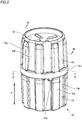
- Fig. 2 is a perspective view showing a syringe cap assembly 10 to be attached to the proximal end of a syringe 11
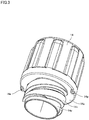
- Fig. 3 is a perspective view as seen from the bottom of a plastic cap 14a
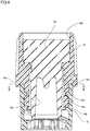
- Fig. 4 is a cross-sectional view as seen in the direction of an arrow-headed line IV-IV in Fig. 2
- Fig. 5 is a perspective view as seen in the direction of an arrow-headed line V-V in Fig. 4 .
- prefilled syringe 1 includes syringe 11 to be filled with a medical liquid or the like, a piston 12 to be inserted in syringe 11, and syringe cap assembly 10 attached to an ejection port at the proximal end of syringe 11.
- Syringe cap assembly 10 includes a lock collar 13, a plastic cap 14 screwed into lock collar 13, and a rubber cap 15 inserted in plastic cap 14.
- Prefilled syringe 1 usually means a condition where syringe 11 has been filled with a liquid medicine or the like. While Fig. 1 shows syringe 11 into which piston 12 has been pushed in to the proximal end of syringe 11 and thus syringe 11 is not filled with the medical liquid any more, the syringe in this state is also referred to herein as prefilled syringe.
- syringe cap assembly 10 includes lock collar 13, plastic cap 14 screwed into lock collar 13, and rubber cap 15 inserted in plastic cap 14, as described above.
- plastic cap 14 a resin material such as polyvinyl chloride, polyethylene, polypropylene, cyclic polyolefin, polystyrene, polyacetal, poly(4-methylpentene-1), polycarbonate, acrylic resin, acrylonitrile-butadiene-styrene copolymer, polyester such as polyethylene terephthalate or polyethylene naphthalate, butadiene-styrene copolymer, polyamide (e.g.
- nylon 6, nylon 6-6, nylon 6-10, nylon 12 ethylene-vinyl alcohol copolymer
- polysulfone polyallylsulfone, polyethersulfone, methacryl-styrene copolymer, polyarylates, or styrene-acrylonitrile copolymer, for example, is used.
- any of various rubber materials such as natural rubber, isoprene rubber, butadiene rubber, styrene-butadiene rubber, nitrile rubber, chloroprene rubber, butyl rubber, acrylic rubber, ethylene-propylene rubber, Hydrin rubber, urethane rubber, silicone rubber, and fluororubber, or any of various thermoplastic elastomers such as styrene-based, polyethylene-based, polyvinyl chloride-based, polyurethane-based, polyester-based, polyamide-based, polybutadiene-based, transpolyisoprene-based, fluororubber-based, and chlorinated polyethylene-based thermoplastic elastomers, or a relatively soft resin material such as polyethylene or vinyl chloride resin, or a combination thereof, for example, may be used.
- the external surface of lock collar 13 in a cylindrical shape has a plurality of projecting ribs 13a that are each extended in the axial direction (the direction indicated by arrows Y in the drawing) and are arranged in the circumferential direction.
- This configuration defines a plurality of recessed grooves 13b that are each extended in the axial direction and located between projecting ribs 13a adjacent to each other in the circumferential direction, among projecting ribs 13a.
- projecting ribs 13a in the present embodiment are arranged at eight respective locations at regular intervals on the external surface of lock collar 13, arrangement of projecting ribs 13a is not limited to this arrangement and the number of projecting ribs 13a and the intervals at which the ribs are arranged, for example, may be changed appropriately depending on the specifications.
- the external surface of plastic cap 14 in a cylindrical shape also has a plurality of projecting ribs 14a that are each extended in the axial direction (the direction indicated by arrows Y in the drawing) and are arranged in the circumferential direction.
- This configuration defines a plurality of recessed grooves 14b that are each extended in the axial direction and located between projecting ribs 14a adjacent to each other in the circumferential direction, among projecting ribs 14a.
- the bottom side (lock collar 13 side) of the external surface of plastic cap 14 has an annular rib 14c surrounding the entire circumference.
- projecting ribs 14a in the present embodiment are arranged at eight respective locations at regular intervals on the external surface of plastic cap 14, arrangement of projecting ribs 14a is not limited to this arrangement and the number of projecting ribs 14a and the intervals at which the ribs are arranged, for example, may be changed appropriately depending on the specifications.
- a bottom 14z of the external surface of plastic cap 14 has a protrusion 14p extending in the direction toward lock collar 13.
- protrusion 14p is placed at each of total two locations facing each other with an angle of 180 degrees between the two locations.
- the inner circumferential surface of cylindrical lock collar 13 has a helical thread 13n
- the outer circumferential surface of a bottom cylindrical portion 14y that extends from the bottom of cylindrical plastic cap 14 in the direction toward lock collar 13 has a thread 14n screwed with helical thread 13n.
- Rubber cap 15 mentioned above is fit into an inner circumferential surface 14h of plastic cap 14.
- the bottom of rubber cap 15 has a recess 15y extending in the axial direction. In the state where plastic cap 14 has been screwed and tightened in lock collar 13, recess 15y is pressed liquid-tight against the ejection port at the proximal end of syringe 11.
- protrusion 14p may be located in recessed groove 13b between projecting ribs 13a. More preferably, as clearly illustrated in Fig. 5 , protrusion 14p may abut against a sidewall of projecting rib 13a that is located upstream in the rotational direction of plastic cap 14.
- protrusion 14p is located in recessed groove 13b between projecting ribs 13a. Accordingly, even if plastic cap 14 is loosened from lock collar 13, protrusion 14p abuts against the sidewall of projecting rib 13a to thereby enable prevention of rotation of plastic cap 14.
- a design can be made to allow the protrusion to abut against the sidewall of projecting rib 13a that is located upstream in the rotational direction of plastic cap 14, at the stage where tightening rotation (in the direction of arrows R in Fig. 5 ) implemented by screwing plastic cap 14 into lock collar 13 is completed, as clearly illustrated in Fig. 5 , to prevent plastic cap 14 from rotating after tightening of plastic cap 14 implemented by screwing plastic cap 14 into lock collar 13 is completed.
- Plastic cap 14 may not necessarily be required to abut against the sidewall of projecting rib 13a, and plastic cap 14 located near this sidewall also produces a substantially equivalent advantageous effect.
Landscapes
- Health & Medical Sciences (AREA)
- Engineering & Computer Science (AREA)
- Hematology (AREA)
- Anesthesiology (AREA)
- Biomedical Technology (AREA)
- Heart & Thoracic Surgery (AREA)
- Vascular Medicine (AREA)
- Life Sciences & Earth Sciences (AREA)
- Animal Behavior & Ethology (AREA)
- General Health & Medical Sciences (AREA)
- Public Health (AREA)
- Veterinary Medicine (AREA)
- Environmental & Geological Engineering (AREA)
- Infusion, Injection, And Reservoir Apparatuses (AREA)
Abstract
Description
- The present invention relates to a syringe cap assembly.
- A prefilled syringe filled aseptically with a liquid medicine has been known. For example,
Japanese Patent Laying-Open No. 2007-029561 - PTL 1:
Japanese Patent Laying-Open No. 2007-029561 - A prefilled syringe has a syringe cap assembly attached to an ejection port at the proximal end of a syringe. Specifically, the syringe cap assembly includes a lock collar and a plastic cap. The lock collar is attached directly to the ejection port at the proximal end of the syringe. The plastic cap is tightened by being screwed into the lock collar and accordingly fastened to the lock collar. A rubber cap is inserted in the plastic cap, and the rubber cap abuts against and covers the ejection port at the proximal end of the syringe to thereby ensure the liquid tightness of the ejection port at the proximal end of the syringe.
- The prefilled syringe filled with a liquid medicine is transported in an individual package. Vibrations or the like occurring during the transportation may cause micro-vibrations of the plastic cap, which may cause the plastic cap tightened into the lock collar to be loosened. In this case, the aseptic condition of the liquid medicine is endangered.
- The present invention has been made in view of the above problem, and an object of the present invention is to provide a syringe cap assembly configured to enable prevention of loosening of a plastic cap tightened into a lock collar.
- The syringe cap assembly is a syringe cap assembly to be attached to an ejection port at a proximal end of a syringe. The syringe cap assembly includes: a lock collar to be attached to the ejection port at the proximal end of the syringe; and a plastic cap screwed and thereby tightened into the lock collar. An external surface of the lock collar has a plurality of projecting ribs that are each extended in an axial direction and are arranged in a circumferential direction to define a plurality of recessed grooves, each recessed groove of the plurality of recessed grooves is extended in the axial direction and located between adjacent projecting ribs of the plurality of projecting ribs, and the adjacent projecting ribs are adjacent to each other in the circumferential direction. A bottom of an external surface of the plastic cap includes a protrusion extending in a direction toward the lock collar. At a stage where tightening rotation of the plastic cap implemented by screwing the plastic cap into the lock collar is completed, the protrusion is located in the recessed groove between the adjacent projecting ribs.
- According to an another aspect, the plurality of projecting ribs are arranged at regular intervals on the external surface of the lock collar to allow the plurality of recessed grooves to be defined at regular intervals on the external surface of the lock collar. At the stage where tightening rotation of the plastic cap implemented by screwing the plastic cap into the lock collar is completed, the protrusion is located near one of the projecting ribs that is located upstream in a rotational direction of the plastic cap.
- According to another aspect, the plurality of projecting ribs are arranged at eight respective locations at regular intervals on the external surface of the lock collar.
- According to another aspect, the protrusion is placed at each of total two locations facing each other with an angle of 180 degrees between the two locations.
- The syringe cap assembly makes it possible to provide a syringe cap assembly configured to enable prevention of loosening of the plastic cap tightened into the lock collar.
-
-
Fig. 1 shows an overall configuration of a prefilled syringe according to an embodiment. -
Fig. 2 is a perspective view showing a syringe cap assembly to be attached to the proximal end of a syringe according to an embodiment. -
Fig. 3 is a perspective view as seen from the bottom of a plastic cap according to an embodiment. -
Fig. 4 is a cross-sectional view as seen in the direction of an arrow-headed line IV-IV inFig. 2 . -
Fig. 5 is a perspective view as seen in the direction of an arrow-headed line V-V inFig. 4 . - A prefilled syringe according to an embodiment is described hereinafter with reference to the drawings. The number, amount, or the like mentioned in connection with embodiments described below does not necessarily limit the scope of the present invention to the mentioned number, amount, or the like, unless otherwise specified. The same parts or corresponding parts are denoted by the same reference numerals, and a description thereof may not be repeated herein. It is intended originally that features of the embodiments may be combined and used appropriately. The drawings are not necessarily drawn to actual scale, and some drawings are drawn to a different scale for facilitating understanding of the structure.
- Referring to
Figs. 1 to 5 , a configuration of a prefilledsyringe 1 according to an embodiment is described.Fig. 1 shows an overall configuration of prefilledsyringe 1,Fig. 2 is a perspective view showing asyringe cap assembly 10 to be attached to the proximal end of asyringe 11,Fig. 3 is a perspective view as seen from the bottom of aplastic cap 14a,Fig. 4 is a cross-sectional view as seen in the direction of an arrow-headed line IV-IV inFig. 2 , andFig. 5 is a perspective view as seen in the direction of an arrow-headed line V-V inFig. 4 . - Referring to
Fig. 1 , prefilledsyringe 1 includessyringe 11 to be filled with a medical liquid or the like, apiston 12 to be inserted insyringe 11, andsyringe cap assembly 10 attached to an ejection port at the proximal end ofsyringe 11. -
Syringe cap assembly 10 includes alock collar 13, aplastic cap 14 screwed intolock collar 13, and arubber cap 15 inserted inplastic cap 14. - Prefilled
syringe 1 usually means a condition wheresyringe 11 has been filled with a liquid medicine or the like. WhileFig. 1 showssyringe 11 into whichpiston 12 has been pushed in to the proximal end ofsyringe 11 and thussyringe 11 is not filled with the medical liquid any more, the syringe in this state is also referred to herein as prefilled syringe. - Referring to
Figs. 2 to 4 ,syringe cap assembly 10 according to the present embodiment includeslock collar 13,plastic cap 14 screwed intolock collar 13, andrubber cap 15 inserted inplastic cap 14, as described above. - For
plastic cap 14, a resin material such as polyvinyl chloride, polyethylene, polypropylene, cyclic polyolefin, polystyrene, polyacetal, poly(4-methylpentene-1), polycarbonate, acrylic resin, acrylonitrile-butadiene-styrene copolymer, polyester such as polyethylene terephthalate or polyethylene naphthalate, butadiene-styrene copolymer, polyamide (e.g. nylon 6, nylon 6-6, nylon 6-10, nylon 12), ethylene-vinyl alcohol copolymer, polysulfone, polyallylsulfone, polyethersulfone, methacryl-styrene copolymer, polyarylates, or styrene-acrylonitrile copolymer, for example, is used. - For
rubber cap 15, any of various rubber materials such as natural rubber, isoprene rubber, butadiene rubber, styrene-butadiene rubber, nitrile rubber, chloroprene rubber, butyl rubber, acrylic rubber, ethylene-propylene rubber, Hydrin rubber, urethane rubber, silicone rubber, and fluororubber, or any of various thermoplastic elastomers such as styrene-based, polyethylene-based, polyvinyl chloride-based, polyurethane-based, polyester-based, polyamide-based, polybutadiene-based, transpolyisoprene-based, fluororubber-based, and chlorinated polyethylene-based thermoplastic elastomers, or a relatively soft resin material such as polyethylene or vinyl chloride resin, or a combination thereof, for example, may be used. - The external surface of
lock collar 13 in a cylindrical shape has a plurality of projectingribs 13a that are each extended in the axial direction (the direction indicated by arrows Y in the drawing) and are arranged in the circumferential direction. This configuration defines a plurality ofrecessed grooves 13b that are each extended in the axial direction and located between projectingribs 13a adjacent to each other in the circumferential direction, among projectingribs 13a. While projectingribs 13a in the present embodiment are arranged at eight respective locations at regular intervals on the external surface oflock collar 13, arrangement of projectingribs 13a is not limited to this arrangement and the number of projectingribs 13a and the intervals at which the ribs are arranged, for example, may be changed appropriately depending on the specifications. - Like
lock collar 13, the external surface ofplastic cap 14 in a cylindrical shape also has a plurality of projectingribs 14a that are each extended in the axial direction (the direction indicated by arrows Y in the drawing) and are arranged in the circumferential direction. This configuration defines a plurality ofrecessed grooves 14b that are each extended in the axial direction and located between projectingribs 14a adjacent to each other in the circumferential direction, among projectingribs 14a. The bottom side (lock collar 13 side) of the external surface ofplastic cap 14 has anannular rib 14c surrounding the entire circumference. - While projecting
ribs 14a in the present embodiment are arranged at eight respective locations at regular intervals on the external surface ofplastic cap 14, arrangement of projectingribs 14a is not limited to this arrangement and the number of projectingribs 14a and the intervals at which the ribs are arranged, for example, may be changed appropriately depending on the specifications. - Referring to
Figs. 2 and3 , abottom 14z of the external surface ofplastic cap 14 has aprotrusion 14p extending in the direction towardlock collar 13. In the present embodiment,protrusion 14p is placed at each of total two locations facing each other with an angle of 180 degrees between the two locations. - Referring to
Fig. 4 , the inner circumferential surface ofcylindrical lock collar 13 has ahelical thread 13n, and the outer circumferential surface of a bottomcylindrical portion 14y that extends from the bottom of cylindricalplastic cap 14 in the direction towardlock collar 13 has athread 14n screwed withhelical thread 13n.Rubber cap 15 mentioned above is fit into an innercircumferential surface 14h ofplastic cap 14. - The bottom of
rubber cap 15 has arecess 15y extending in the axial direction. In the state whereplastic cap 14 has been screwed and tightened inlock collar 13,recess 15y is pressed liquid-tight against the ejection port at the proximal end ofsyringe 11. - Referring to
Figs. 2 and5 , at the stage where tightening rotation (in the direction indicated by arrows R inFig. 5 ) ofplastic cap 14 that is implemented by screwingplastic cap 14 intolock collar 13 is completed,protrusion 14p may be located in recessedgroove 13b between projectingribs 13a. More preferably, as clearly illustrated inFig. 5 ,protrusion 14p may abut against a sidewall of projectingrib 13a that is located upstream in the rotational direction ofplastic cap 14. - Thus, in
syringe cap assembly 10 according to the present embodiment, at the stage where tightening rotation (in the direction of arrows R inFig. 5 ) ofplastic cap 14 that is implemented by screwingplastic cap 14 intolock collar 13 is completed,protrusion 14p is located in recessedgroove 13b between projectingribs 13a. Accordingly, even ifplastic cap 14 is loosened fromlock collar 13,protrusion 14p abuts against the sidewall of projectingrib 13a to thereby enable prevention of rotation ofplastic cap 14. - More preferably, a design can be made to allow the protrusion to abut against the sidewall of projecting
rib 13a that is located upstream in the rotational direction ofplastic cap 14, at the stage where tightening rotation (in the direction of arrows R inFig. 5 ) implemented by screwingplastic cap 14 intolock collar 13 is completed, as clearly illustrated inFig. 5 , to preventplastic cap 14 from rotating after tightening ofplastic cap 14 implemented by screwingplastic cap 14 intolock collar 13 is completed.Plastic cap 14 may not necessarily be required to abut against the sidewall of projectingrib 13a, andplastic cap 14 located near this sidewall also produces a substantially equivalent advantageous effect. - While the foregoing embodiment employs the configuration where projecting
ribs 14a are arranged at eight respective locations at regular intervals on the external surface ofplastic cap 14 andprotrusion 14p is placed at each of total two locations facing each other with an angle of 180 degrees between the two locations, its configuration is not limited to this configuration andprotrusion 14p may be provided at one or more locations. - The above embodiments disclosed herein are given by way of illustration in all respects, not as grounds for limited interpretation. The technical scope of the present invention is therefore defined by the description of claims, not to be interpreted solely from the above embodiments, and encompasses all variations equivalent in meaning and scope to the claims.
- 1 prefilled syringe; 11 syringe; 12 piston; 10 syringe cap assembly; 13 lock collar; 13a projecting rib; 13b recessed groove; 13n helical thread; 14 plastic cap; 14a projecting rib; 14b recessed groove; 14c annular rib; 14h inner circumferential surface; 14n thread; 14p protrusion; 14y bottom cylindrical portion; 14z bottom; 15 rubber cap; 15y recess
Claims (4)
- A syringe cap assembly to be attached to an ejection port at a proximal end of a syringe, the syringe cap assembly comprising:a lock collar to be attached to the ejection port at the proximal end of the syringe; anda plastic cap screwed and thereby tightened into the lock collar, whereinan external surface of the lock collar has a plurality of projecting ribs that are each extended in an axial direction and are arranged in a circumferential direction to define a plurality of recessed grooves, each recessed groove of the plurality of recessed grooves is extended in the axial direction and located between adjacent projecting ribs of the plurality of projecting ribs, and the adjacent projecting ribs are adjacent to each other in the circumferential direction,a bottom of an external surface of the plastic cap includes a protrusion extending in a direction toward the lock collar, andat a stage where tightening rotation of the plastic cap implemented by screwing the plastic cap into the lock collar is completed, the protrusion is located in the recessed groove between the adjacent projecting ribs.
- The syringe cap assembly according to claim 1, whereinthe plurality of projecting ribs are arranged at regular intervals on the external surface of the lock collar to allow the plurality of recessed grooves to be defined at regular intervals on the external surface of the lock collar, andat the stage where tightening rotation of the plastic cap implemented by screwing the plastic cap into the lock collar is completed, the protrusion is located near one of the projecting ribs that is located upstream in a rotational direction of the plastic cap.
- The syringe cap assembly according to claim 2, wherein the plurality of projecting ribs are arranged at eight respective locations at regular intervals on the external surface of the lock collar.
- The syringe cap assembly according to any one of claims 1 to 3, wherein the protrusion is placed at each of total two locations facing each other with an angle of 180 degrees between the two locations.
Applications Claiming Priority (2)
| Application Number | Priority Date | Filing Date | Title |
|---|---|---|---|
| JP2019007497A JP7454910B2 (en) | 2019-01-21 | 2019-01-21 | Syringe cap assembly |
| PCT/JP2020/000383 WO2020153131A1 (en) | 2019-01-21 | 2020-01-09 | Syringe cap assembly |
Publications (2)
| Publication Number | Publication Date |
|---|---|
| EP3909625A1 true EP3909625A1 (en) | 2021-11-17 |
| EP3909625A4 EP3909625A4 (en) | 2022-09-28 |
Family
ID=71736022
Family Applications (1)
| Application Number | Title | Priority Date | Filing Date |
|---|---|---|---|
| EP20745523.9A Withdrawn EP3909625A4 (en) | 2019-01-21 | 2020-01-09 | Syringe cap assembly |
Country Status (6)
| Country | Link |
|---|---|
| US (1) | US20220080129A1 (en) |
| EP (1) | EP3909625A4 (en) |
| JP (1) | JP7454910B2 (en) |
| CN (1) | CN113853224A (en) |
| MX (1) | MX2021008706A (en) |
| WO (1) | WO2020153131A1 (en) |
Families Citing this family (4)
| Publication number | Priority date | Publication date | Assignee | Title |
|---|---|---|---|---|
| JP1726353S (en) * | 2022-05-30 | 2022-10-03 | syringe cap | |
| JP2025529575A (en) * | 2022-09-19 | 2025-09-04 | ベクトン ディキンソン フランス | Tip caps for medical syringes |
| EP4344717B1 (en) * | 2022-09-28 | 2026-08-12 | Becton, Dickinson and Company | Sealing cap for a syringe tip |
| USD1069110S1 (en) * | 2023-02-21 | 2025-04-01 | Vetter Pharma-Fertigung GmbH & Co. KG | Syringe cap |
Family Cites Families (19)
| Publication number | Priority date | Publication date | Assignee | Title |
|---|---|---|---|---|
| US5624402A (en) * | 1994-12-12 | 1997-04-29 | Becton, Dickinson And Company | Syringe tip cap |
| US6632199B1 (en) * | 2000-05-23 | 2003-10-14 | Becton Dickinson And Company | Syringe assembly including plastic tip cap |
| US20040225258A1 (en) | 2002-03-30 | 2004-11-11 | Ernest Balestracci | Tamper evident overcap for a container |
| ES2293416T3 (en) | 2004-05-29 | 2008-03-16 | Gerresheimer Bunde Gmbh | SYRINGE CLOSURE AND PROCEDURE FOR MANUFACTURING AND A SYRINGE CLOSURE. |
| JP3970294B2 (en) * | 2005-07-28 | 2007-09-05 | シャープ株式会社 | Drum drying washing machine |
| JP4723303B2 (en) * | 2005-07-28 | 2011-07-13 | テルモ株式会社 | Prefilled syringe |
| DE102008013198B4 (en) * | 2008-03-07 | 2011-07-14 | Bayer Schering Pharma Aktiengesellschaft, 13353 | Tamper evident closure with retaining pin |
| JP5283417B2 (en) | 2008-03-31 | 2013-09-04 | テルモ株式会社 | Cap and prefilled syringe manufacturing method |
| US9919113B2 (en) * | 2009-06-03 | 2018-03-20 | Becton Dickinson France | Luer lock adaptor |
| JP5779173B2 (en) * | 2010-03-03 | 2015-09-16 | テルモ株式会社 | Syringe |
| KR20130017766A (en) * | 2011-08-12 | 2013-02-20 | 조희민 | Syringe cap for preventing reuse |
| DE102011120637A1 (en) * | 2011-12-09 | 2013-06-13 | Schott Schweiz Ag | Closure, in particular syringe closure for the sealing closing of a distal opening of a syringe body |
| ITBO20120151A1 (en) * | 2012-03-21 | 2013-09-22 | Maccaferri Spa Off | GABBIONE REINFORCED AND PROCEDURE FOR ITS MANUFACTURE |
| EP2832391B1 (en) * | 2012-03-28 | 2018-01-03 | Terumo Kabushiki Kaisha | Syringe |
| EP2928528A1 (en) * | 2012-12-07 | 2015-10-14 | SCHOTT Schweiz AG | Closure piece, in particular a syringe closure piece for closing a distal opening of a syringe body in a sealed manner |
| JP2016179117A (en) * | 2015-03-25 | 2016-10-13 | テルモ株式会社 | Pre-filled syringe |
| CN108883233B (en) * | 2016-04-15 | 2021-10-01 | 泰尔茂株式会社 | Syringe barrel, its manufacturing method, and prefilled syringe |
| EP3570810B1 (en) * | 2017-01-17 | 2025-09-24 | Becton Dickinson and Company Limited | Syringe adapter with cap |
| KR101750352B1 (en) * | 2017-04-12 | 2017-06-23 | 조희민 | Syringe cap for preventing reuse |
-
2019
- 2019-01-21 JP JP2019007497A patent/JP7454910B2/en active Active
-
2020
- 2020-01-09 EP EP20745523.9A patent/EP3909625A4/en not_active Withdrawn
- 2020-01-09 US US17/424,053 patent/US20220080129A1/en not_active Abandoned
- 2020-01-09 WO PCT/JP2020/000383 patent/WO2020153131A1/en not_active Ceased
- 2020-01-09 CN CN202080021232.9A patent/CN113853224A/en active Pending
- 2020-01-09 MX MX2021008706A patent/MX2021008706A/en unknown
Also Published As
| Publication number | Publication date |
|---|---|
| CN113853224A (en) | 2021-12-28 |
| WO2020153131A1 (en) | 2020-07-30 |
| MX2021008706A (en) | 2021-10-01 |
| JP7454910B2 (en) | 2024-03-25 |
| JP2020115965A (en) | 2020-08-06 |
| US20220080129A1 (en) | 2022-03-17 |
| EP3909625A4 (en) | 2022-09-28 |
Similar Documents
| Publication | Publication Date | Title |
|---|---|---|
| US20220080129A1 (en) | Syringe cap assembly | |
| JP5782506B2 (en) | Barrel with cap, prefilled syringe, and cap with connector | |
| KR102160026B1 (en) | Adaptor for a drug delivery device and method for mounting said adaptor thereon | |
| ES2293416T3 (en) | SYRINGE CLOSURE AND PROCEDURE FOR MANUFACTURING AND A SYRINGE CLOSURE. | |
| EP2376147B1 (en) | Improved drug container | |
| US8056756B2 (en) | Communication member and medical container using the same | |
| JPWO2018164250A1 (en) | Syringe assembly and prefilled syringe | |
| EP2913076B1 (en) | Syringe | |
| ES2903139T3 (en) | Improved mechanical friction for a threaded connection incorporating micro-threads | |
| EP2689798A1 (en) | Connecter assembly, male connecter, and female connecter | |
| JPWO2014102987A1 (en) | Prefilled syringe outer cylinder and prefilled syringe outer cylinder package | |
| US11660402B2 (en) | Syringe and prefilled syringe | |
| EP3269418A1 (en) | Tip cap assembly, medical injection system and process for producing a medical injection system | |
| WO2018038078A1 (en) | Medical equipment package | |
| EP3006067B1 (en) | Syringe and prefilled syringe | |
| JP7573162B2 (en) | Medical Connectors | |
| US11311680B2 (en) | Female syringe and syringe kit | |
| WO2011046210A1 (en) | Cap, and nutritional agent container and nutritional agent supply set that use same | |
| US11998722B2 (en) | Female syringe barrel, syringe kit, and syringe connection method | |
| US10688245B2 (en) | Plunger for syringe and pre-filled syringe including the same | |
| JP6715557B2 (en) | Syringe and prefilled syringe | |
| JP7740255B2 (en) | Conversion connector | |
| JP5144454B2 (en) | Prefilled syringe | |
| JP3191047U (en) | Prefilled syringe and prefilled syringe | |
| JP2009000194A (en) | Syringe |
Legal Events
| Date | Code | Title | Description |
|---|---|---|---|
| STAA | Information on the status of an ep patent application or granted ep patent |
Free format text: STATUS: THE INTERNATIONAL PUBLICATION HAS BEEN MADE |
|
| PUAI | Public reference made under article 153(3) epc to a published international application that has entered the european phase |
Free format text: ORIGINAL CODE: 0009012 |
|
| STAA | Information on the status of an ep patent application or granted ep patent |
Free format text: STATUS: REQUEST FOR EXAMINATION WAS MADE |
|
| 17P | Request for examination filed |
Effective date: 20210813 |
|
| AK | Designated contracting states |
Kind code of ref document: A1 Designated state(s): AL AT BE BG CH CY CZ DE DK EE ES FI FR GB GR HR HU IE IS IT LI LT LU LV MC MK MT NL NO PL PT RO RS SE SI SK SM TR |
|
| DAV | Request for validation of the european patent (deleted) | ||
| DAX | Request for extension of the european patent (deleted) | ||
| A4 | Supplementary search report drawn up and despatched |
Effective date: 20220825 |
|
| RIC1 | Information provided on ipc code assigned before grant |
Ipc: A61M 5/178 20060101ALI20220819BHEP Ipc: A61M 5/32 20060101ALI20220819BHEP Ipc: A61M 5/31 20060101ALI20220819BHEP Ipc: A61M 5/28 20060101AFI20220819BHEP |
|
| GRAP | Despatch of communication of intention to grant a patent |
Free format text: ORIGINAL CODE: EPIDOSNIGR1 |
|
| STAA | Information on the status of an ep patent application or granted ep patent |
Free format text: STATUS: GRANT OF PATENT IS INTENDED |
|
| INTG | Intention to grant announced |
Effective date: 20250117 |
|
| STAA | Information on the status of an ep patent application or granted ep patent |
Free format text: STATUS: THE APPLICATION IS DEEMED TO BE WITHDRAWN |
|
| 18D | Application deemed to be withdrawn |
Effective date: 20250520 |