EP3909554A1 - A transportation vehicle for a person or persons sitting in a wheelchair or wheelchairs - Google Patents
A transportation vehicle for a person or persons sitting in a wheelchair or wheelchairs Download PDFInfo
- Publication number
- EP3909554A1 EP3909554A1 EP21171527.1A EP21171527A EP3909554A1 EP 3909554 A1 EP3909554 A1 EP 3909554A1 EP 21171527 A EP21171527 A EP 21171527A EP 3909554 A1 EP3909554 A1 EP 3909554A1
- Authority
- EP
- European Patent Office
- Prior art keywords
- top floor
- profiles
- floor
- transportation vehicle
- profile
- Prior art date
- Legal status (The legal status is an assumption and is not a legal conclusion. Google has not performed a legal analysis and makes no representation as to the accuracy of the status listed.)
- Granted
Links
Images

Classifications
-
- A—HUMAN NECESSITIES
- A61—MEDICAL OR VETERINARY SCIENCE; HYGIENE
- A61G—TRANSPORT, PERSONAL CONVEYANCES, OR ACCOMMODATION SPECIALLY ADAPTED FOR PATIENTS OR DISABLED PERSONS; OPERATING TABLES OR CHAIRS; CHAIRS FOR DENTISTRY; FUNERAL DEVICES
- A61G3/00—Ambulance aspects of vehicles; Vehicles with special provisions for transporting patients or disabled persons, or their personal conveyances, e.g. for facilitating access of, or for loading, wheelchairs
- A61G3/08—Accommodating or securing wheelchairs or stretchers
- A61G3/0808—Accommodating or securing wheelchairs
-
- B—PERFORMING OPERATIONS; TRANSPORTING
- B60—VEHICLES IN GENERAL
- B60P—VEHICLES ADAPTED FOR LOAD TRANSPORTATION OR TO TRANSPORT, TO CARRY, OR TO COMPRISE SPECIAL LOADS OR OBJECTS
- B60P7/00—Securing or covering of load on vehicles
- B60P7/06—Securing of load
- B60P7/08—Securing to the vehicle floor or sides
- B60P7/0807—Attachment points
-
- B—PERFORMING OPERATIONS; TRANSPORTING
- B62—LAND VEHICLES FOR TRAVELLING OTHERWISE THAN ON RAILS
- B62D—MOTOR VEHICLES; TRAILERS
- B62D25/00—Superstructure or monocoque structure sub-units; Parts or details thereof not otherwise provided for
- B62D25/20—Floors or bottom sub-units
- B62D25/2054—Load carrying floors for commercial vehicles
Definitions
- the transportation of people sitting in a wheelchair requires specific measures to secure that both the wheelchair and the person sitting in the wheelchair are safely tied to the transportation vehicle so as to prevent injuries during a collision.
- the known transportation vehicle is tailored with specific features, notably the above mentioned rollers with safety straps, that make it possible that the wheelchair is fixated in position on the top floor of the transportation vehicle.
- top floor and the transportation vehicle of the invention have the features of one or more of the appended claims.
- the top floor comprises an open U-profile or U-profiles consisting of a bottom wall and two oppositely arranged up-standing sidewalls on the bottom wall only, which open U-profile or U-profiles provide the cavity or cavities which house the rollers, wherein said U-profiles are mounted on a frame with longitudinal runners and transversal girders to provide the top floor with longitudinal and transversal rigidity.
- the term 'longitudinal' as used herein refers to the normal forward direction of travel of the vehicle, whereas the term 'transversal' refers to a direction which is at right angles with the longitudinal direction.
- the construction with the U-profile or U-profiles provides versatility and reduces weight, since the U-profile or U-profiles are then only applied at places where rollers with safety straps need to be accommodated. It is therefore preferred in the invention that the said U-profile or U-profiles extend only over a restricted part of the top floor which is in essence limited to provide only the cavity or cavities housing the rollers with safety straps.
- the reduction of weight and versatility of the transportation vehicle of the invention is further promoted in an embodiment wherein there are multiple U-profiles located in the top floor one behind the other and/or one adjacent to the other for fixing a series of wheelchairs behind and/or next to each other on top of the top floor, wherein the multiple U-profiles leave a space between them without the respective U-profiles abutting against each other.
- the top floor comprises a composite surface layer on top of the U-profile or U-profiles. Applying such a composite surface layer is a low weight solution for completing the top floor.
- the composite surface layer comprises a PP core layer with an anti-slip layer on top. This provides both strength and safety in use.
- the ant-slip layer is one of a glass fiber liner or a carbon fiber liner.
- the composite surface layer is provided on top of the frame with a glue connection whilst avoiding screw connections.
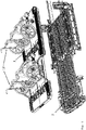
- the transportation vehicle comprises a top floor 1 mounted on top of an existing floor 2 of the vehicle, as shown in figure 1 .
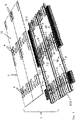
- Figure 2 shows that the top floor 1 has cavities 3 that are approachable through apertures 4 in a cover layer or surface layer 5 that forms part of the top floor 1.
- the cavities 3 house arrestable rollers 6 supporting safety straps for fixing the wheelchair or wheelchairs 12 shown in figure 1 in position on the top floor 1.
- the provision of the arrestable rollers 6 with the safety straps in the floor is as such also known from the prior art, and not further elucidated with reference to the figures.
- the top floor 1 comprises an open U-profile or U-profiles 7 consisting of a bottom wall and two oppositely arranged upstanding sidewalls on the bottom wall only, which open U-profile or U-profiles 7 provide the cavity or cavities 3 which house the rollers 6, wherein said U-profiles 7 are mounted on a frame with longitudinal runners 8 and transversal girders 9 to provide the top floor 1 with longitudinal and transversal rigidity.
- U-profiles 7 are mounted on a frame with longitudinal runners 8 and transversal girders 9 to provide the top floor 1 with longitudinal and transversal rigidity.
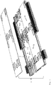
- FIGS 3 and 4 further depict that wherein there are indeed multiple U-profiles 7.1, 7.2, 7.3 and 7.4 located in the top floor 1 one behind the other (7.1 and 7.2) and/or one adjacent to the other (7.3 and 7.4), the multiple U-profiles 7.1, 7.2, 7.3 and 7.4 leave a space 10.1 and 10.2 between them without the respective U-profiles 7.1, 7.2, 7.3 and 7.4 abutting against each other.
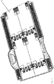
- the location of the U-profiles 7.1, 7.2, 7.3 and 7.4 is then each time selected to enable fixing a series of wheelchairs one behind the other and/or next to each other on top of the top floor 1. These locations are clearly recognizable in figure 5 showing the completed top floor 1.
- the top floor 1 comprises a composite cover layer or surface layer 5 on top of the U-profile or U-profiles 7.
- the composite surface layer 5 comprises a PP core layer with an anti-slip layer 11 on top.
- the ant-slip layer 11 is preferably selected to be one of a glass fiber liner or a carbon fiber liner.
Landscapes
- Engineering & Computer Science (AREA)
- Transportation (AREA)
- Mechanical Engineering (AREA)
- Health & Medical Sciences (AREA)
- Public Health (AREA)
- Chemical & Material Sciences (AREA)
- Combustion & Propulsion (AREA)
- Life Sciences & Earth Sciences (AREA)
- Animal Behavior & Ethology (AREA)
- General Health & Medical Sciences (AREA)
- Veterinary Medicine (AREA)
- Body Structure For Vehicles (AREA)
Abstract
Description
- The invention relates to a transportation vehicle for a person or persons sitting in a wheelchair or wheelchairs, comprising a top floor mounted on top of an existing floor of the vehicle, wherein the top floor has cavities that house arrestable rollers supporting safety straps for fixing the wheelchair or wheelchairs in position on the top floor. The invention also relates to said top floor.
- Such a transportation vehicle is known from
WO2005/037597 and in day-to-day use for the transportation of people sitting in a wheelchair. - The transportation of people sitting in a wheelchair requires specific measures to secure that both the wheelchair and the person sitting in the wheelchair are safely tied to the transportation vehicle so as to prevent injuries during a collision. For this purpose the known transportation vehicle is tailored with specific features, notably the above mentioned rollers with safety straps, that make it possible that the wheelchair is fixated in position on the top floor of the transportation vehicle.
- It is comparatively expensive to convert a standard transportation vehicle and make it suitable for the transportation of wheelchairs with persons sitting in these wheelchairs. One object of the invention is to reduce these conversion costs.
- Moreover there is a need in this field to increase the versatility of a vehicle that is converted in a transportation vehicle, so that it can easily accommodate different wheelchair arrangements. Another object is therefore to make it easier to accommodate different wheelchair arrangements in such a converted vehicle.
- Still another object of the invention is to reduce the weight added with the top floor to the converted vehicle, without sacrificing rigidity in the longitudinal and transversal direction.
- The invention is aimed to address these and other objects and to provide advantages that will become apparent from the following disclosure.
- The top floor and the transportation vehicle of the invention have the features of one or more of the appended claims.
- According to a first aspect of the invention the top floor comprises an open U-profile or U-profiles consisting of a bottom wall and two oppositely arranged up-standing sidewalls on the bottom wall only, which open U-profile or U-profiles provide the cavity or cavities which house the rollers, wherein said U-profiles are mounted on a frame with longitudinal runners and transversal girders to provide the top floor with longitudinal and transversal rigidity. The term 'longitudinal' as used herein refers to the normal forward direction of travel of the vehicle, whereas the term 'transversal' refers to a direction which is at right angles with the longitudinal direction.
- The construction with the U-profile or U-profiles provides versatility and reduces weight, since the U-profile or U-profiles are then only applied at places where rollers with safety straps need to be accommodated. It is therefore preferred in the invention that the said U-profile or U-profiles extend only over a restricted part of the top floor which is in essence limited to provide only the cavity or cavities housing the rollers with safety straps.
- The reduction of weight and versatility of the transportation vehicle of the invention is further promoted in an embodiment wherein there are multiple U-profiles located in the top floor one behind the other and/or one adjacent to the other for fixing a series of wheelchairs behind and/or next to each other on top of the top floor, wherein the multiple U-profiles leave a space between them without the respective U-profiles abutting against each other.
- Preferably the top floor comprises a composite surface layer on top of the U-profile or U-profiles. Applying such a composite surface layer is a low weight solution for completing the top floor.
- Preferably the composite surface layer comprises a PP core layer with an anti-slip layer on top. This provides both strength and safety in use.
- Suitably the ant-slip layer is one of a glass fiber liner or a carbon fiber liner.
- In a further aspect of the engine the composite surface layer is provided on top of the frame with a glue connection whilst avoiding screw connections.
- Advantageously the glue connection comprises double-sided tape.
- The invention will hereinafter be further elucidated with reference to the drawing of an exemplary embodiment of parts of a transportation vehicle according to the invention that is not limiting as to the appended claims.
- In the drawing:
-
figure 1 provides a perspective view at a floor of a transportation vehicle according to the invention; -
figure 2 shows an exploded view of a part of the floor offigure 1 ; -
figure 3 provides a view at some non-assembled elements of the floor offigure 1 ; -
figure 4 provides another view at some non-assembled elements of the floor offigure 1 ; and -
figure 5 provides a top perspective view at the floor offigure 1 . - Whenever in the figures the same reference numerals are applied, these numerals refer to the same parts.
- The appended figures are for clarity limited to show only those features that are relevant for the invention. The skilled person knows how a transportation vehicle for a person or persons sitting in a wheelchair or wheelchairs is construed, and this is therefore not shown in the figures.
- Common to the prior art and to the invention is that the transportation vehicle comprises a
top floor 1 mounted on top of an existingfloor 2 of the vehicle, as shown infigure 1 .Figure 2 shows that thetop floor 1 hascavities 3 that are approachable throughapertures 4 in a cover layer orsurface layer 5 that forms part of thetop floor 1. Thecavities 3 housearrestable rollers 6 supporting safety straps for fixing the wheelchair orwheelchairs 12 shown infigure 1 in position on thetop floor 1. The provision of thearrestable rollers 6 with the safety straps in the floor is as such also known from the prior art, and not further elucidated with reference to the figures. - Turning further to
figure 2 , it is shown that thetop floor 1 comprises an open U-profile or U-profiles 7 consisting of a bottom wall and two oppositely arranged upstanding sidewalls on the bottom wall only, which open U-profile or U-profiles 7 provide the cavity orcavities 3 which house therollers 6, wherein said U-profiles 7 are mounted on a frame withlongitudinal runners 8 andtransversal girders 9 to provide thetop floor 1 with longitudinal and transversal rigidity. A better view at the frame with thelongitudinal runners 8, thetransversal girders 9 and the U-profiles 7 is provided byfigures 3 and4 . Thesefigures 3 and4 also depict that the said U-profile or U-profiles 7 extend only over a restricted part of thetop floor 1 which is in essence limited to provide only the cavity orcavities 3 housing therollers 6. See for instance the restricted length of the multiple U-profiles 7.1, 7.2, 7.3 and 7.4. -
Figures 3 and4 further depict that wherein there are indeed multiple U-profiles 7.1, 7.2, 7.3 and 7.4 located in thetop floor 1 one behind the other (7.1 and 7.2) and/or one adjacent to the other (7.3 and 7.4), the multiple U-profiles 7.1, 7.2, 7.3 and 7.4 leave a space 10.1 and 10.2 between them without the respective U-profiles 7.1, 7.2, 7.3 and 7.4 abutting against each other. The location of the U-profiles 7.1, 7.2, 7.3 and 7.4 is then each time selected to enable fixing a series of wheelchairs one behind the other and/or next to each other on top of thetop floor 1. These locations are clearly recognizable infigure 5 showing the completedtop floor 1. - As already mentioned with reference to
figure 2 , alsofigure 3 and4 show that thetop floor 1 comprises a composite cover layer orsurface layer 5 on top of the U-profile or U-profiles 7. Preferably thecomposite surface layer 5 comprises a PP core layer with ananti-slip layer 11 on top. The ant-slip layer 11 is preferably selected to be one of a glass fiber liner or a carbon fiber liner. - The composite surface layer is provided on top of the frame of the
longitudinal runners 8 andtransversal girders 9 with a glue connection whilst avoiding screw connections. Preferably the glue connection comprises double-sided tape. - Although the invention has been discussed in the foregoing with reference to an exemplary embodiment of a floor of the transportation vehicle of the invention, the invention is not restricted to this particular embodiment which can be varied in many ways without departing from the invention. The discussed exemplary embodiment shall therefore not be used to construe the appended claims strictly in accordance therewith. On the contrary the embodiment is merely intended to explain the wording of the appended claims without intent to limit the claims to this exemplary embodiment. The scope of protection of the invention shall therefore be construed in accordance with the appended claims only, wherein a possible ambiguity in the wording of the claims shall be resolved using this exemplary embodiment.
Claims (16)
- A transportation vehicle for a person or persons sitting in a wheelchair or wheelchairs, comprising a top floor (1) mounted on top of a floor (2) of the vehicle, wherein the top floor (1) has cavities (3) that house arrestable rollers (6) supporting safety straps for fixing the wheelchair or wheelchairs (12) in position on the top floor (1), characterized in that the top floor (1) comprises an open U-profile or U-profiles (7) consisting of a bottom wall and two oppositely arranged upstanding sidewalls on the bottom wall only, which open U-profile or U-profiles (7) provide the cavity or cavities (3) which house the rollers (6), wherein said U-profiles (7) are mounted on a frame with longitudinal runners (8) and transversal girders (9) to provide the top floor (1) with longitudinal and transversal rigidity.
- Transportation vehicle according to claim 1, characterized in that the said U-profile or U-profiles (7) extend only over a restricted part of the top floor (1) which is in essence limited to provide only the cavity or cavities (3) housing the rollers (6).
- Transportation vehicle according to claim 1 or 2, characterized in that wherein there are multiple U-profiles (7.1, 7.2, 7.3, 7.4) located in the top floor (1) one behind the other and/or one adjacent to the other for fixing a series of wheelchairs (12) behind and/or next to each other on top of the top floor (1), wherein the multiple U-profiles (7.1, 7.2, 7.3, 7.4) leave a space (10.1, 10.2) between them without the respective U-profiles (7.1, 7.2, 7.3, 7.4) abutting against each other.
- Transportation vehicle according to any one of claims 1 - 3, characterized in that the top floor (1) comprises a composite surface layer (5) on top of the U-profile or U-profiles (7, 7.1, 7.2, 7.3, 7.4).
- Transportation vehicle according to claim 4, characterized in that the composite surface layer (5) comprises a PP core layer with an anti-slip layer (11) on top.
- Transportation vehicle according to claim 5, characterized in that the ant-slip layer (11) is one of a glass fiber liner or a carbon fiber liner.
- Transportation vehicle according to any one of claims 1 - 3 and any one of claims 4 - 6, characterized in that the composite surface layer (5) is provided on top of the frame with a glue connection whilst avoiding screw connections.
- Transportation vehicle according to claim 7, characterized in that the glue connection comprises double-sided tape.
- Top floor (1) for mounting on top of a floor (2) of a vehicle, wherein the top floor (1) has cavities (3) that house arrestable rollers (6) supporting safety straps for fixing a wheelchair or wheelchairs (12) in position on the top floor (1), characterized in that the top floor (1) comprises an open U-profile or U-profiles (7) consisting of a bottom and two oppositely arranged upstanding sidewalls on the bottom only that provide the cavity or cavities (3) which house the rollers (6), wherein said U-profiles (7) are mounted on a frame with longitudinal runners (8) and transversal girders (9) to provide the top floor (1) with longitudinal and transversal rigidity.
- Top floor (1) according to claim 9, characterized in that the said U-profile or U-profiles (7) extend only over a restricted part of the top floor (1) which is in essence limited to provide only the cavity or cavities (3) housing the rollers (6).
- Top floor (1) according to claim 9 or 10, characterized in that wherein there are multiple U-profiles (7.1, 7.2, 7.3, 7.4) located in the top floor (1) one behind the other and/or one adjacent to the other for fixing a series of wheelchairs (12) behind and/or next to each other on top of the top floor (1), wherein the multiple U-profiles (7.1, 7.2, 7.3, 7.4) leave a space (10.1, 10.2) between them without the respective U-profiles (7.1, 7.2, 7.3, 7.4) abutting against each other.
- Top floor (1) according to any one of claims 9 - 11, characterized in that the top floor (1) comprises a composite surface layer (5) on top of the U-profile or U-profiles (7, 7.1, 7.2, 7.3, 7.4).
- Top floor (1) according to claim 12, characterized in that the composite surface layer (5) comprises a PP core layer with an anti-slip layer (11) on top.
- Top floor (1) according to claim 13, characterized in that the ant-slip layer (11) is one of a glass fiber liner or a carbon fiber liner.
- Top floor (1) according to any one of claims 9 - 11 and any one of claims 12 - 14, characterized in that the composite surface layer (5) is provided on top of the frame with a glue connection whilst avoiding screw connections.
- Top floor (1) according to claim 15, characterized in that the glue connection comprises double-sided tape.
Applications Claiming Priority (1)
| Application Number | Priority Date | Filing Date | Title |
|---|---|---|---|
| NL2025581A NL2025581B1 (en) | 2020-05-14 | 2020-05-14 | A transportation vehicle for a person or persons sitting in a wheelchair or wheelchairs |
Publications (3)
| Publication Number | Publication Date |
|---|---|
| EP3909554A1 true EP3909554A1 (en) | 2021-11-17 |
| EP3909554C0 EP3909554C0 (en) | 2024-08-21 |
| EP3909554B1 EP3909554B1 (en) | 2024-08-21 |
Family
ID=71452723
Family Applications (1)
| Application Number | Title | Priority Date | Filing Date |
|---|---|---|---|
| EP21171527.1A Active EP3909554B1 (en) | 2020-05-14 | 2021-04-30 | A transportation vehicle for a person or persons sitting in a wheelchair or wheelchairs |
Country Status (4)
| Country | Link |
|---|---|
| EP (1) | EP3909554B1 (en) |
| ES (1) | ES2992153T3 (en) |
| NL (1) | NL2025581B1 (en) |
| PL (1) | PL3909554T3 (en) |
Citations (3)
| Publication number | Priority date | Publication date | Assignee | Title |
|---|---|---|---|---|
| WO2005037597A1 (en) | 2003-10-22 | 2005-04-28 | Beheers & Beleggingsmaatschappij Verachtert B.V. | Improved floor mounted on the bottom plate of transport vehicles for fastening chairs / seats and wheelchairs |
| GB2427176A (en) * | 2005-06-13 | 2006-12-20 | Unwin C N Ltd | Vehicle floor with integral load securing formations |
| EP2108349A1 (en) * | 2008-04-10 | 2009-10-14 | Tribus B.V. | Centrally operated mechanical roll-up strap system for use in means of transport |
-
2020
- 2020-05-14 NL NL2025581A patent/NL2025581B1/en active
-
2021
- 2021-04-30 EP EP21171527.1A patent/EP3909554B1/en active Active
- 2021-04-30 ES ES21171527T patent/ES2992153T3/en active Active
- 2021-04-30 PL PL21171527.1T patent/PL3909554T3/en unknown
Patent Citations (4)
| Publication number | Priority date | Publication date | Assignee | Title |
|---|---|---|---|---|
| WO2005037597A1 (en) | 2003-10-22 | 2005-04-28 | Beheers & Beleggingsmaatschappij Verachtert B.V. | Improved floor mounted on the bottom plate of transport vehicles for fastening chairs / seats and wheelchairs |
| EP1701860A1 (en) * | 2003-10-22 | 2006-09-20 | Beheers & Beleggingsmaatschappij Verachtert B.V. | Improved floor mounted on the bottom plate of transport vehicles for fastening chairs / seats and wheelchairs |
| GB2427176A (en) * | 2005-06-13 | 2006-12-20 | Unwin C N Ltd | Vehicle floor with integral load securing formations |
| EP2108349A1 (en) * | 2008-04-10 | 2009-10-14 | Tribus B.V. | Centrally operated mechanical roll-up strap system for use in means of transport |
Also Published As
| Publication number | Publication date |
|---|---|
| EP3909554C0 (en) | 2024-08-21 |
| NL2025581B1 (en) | 2021-11-30 |
| ES2992153T3 (en) | 2024-12-09 |
| PL3909554T3 (en) | 2025-01-20 |
| EP3909554B1 (en) | 2024-08-21 |
Similar Documents
| Publication | Publication Date | Title |
|---|---|---|
| US20030168281A1 (en) | Stairway for enabling access to an overhead area within a fuselage of an aircraft | |
| EP2727822B1 (en) | Aircraft having a recessed cavity in an aft pressure bulkhead wall surface and a galley moved rearwardly into the recessed cavity increasing floor space in front of the galley | |
| ATE201359T1 (en) | SELF-SUPPORTING REFRIGERATED TRUCK | |
| ES468751A1 (en) | PERFECTED SYSTEM TO PROTECT THE OCCUPANTS OF A MOTOR VEHICLE FROM DAMAGE IN SIDE COLLISIONS | |
| DK2031149T3 (en) | Laminate floor panel | |
| MXPA04001538A (en) | Interlocking deck support system | |
| EP3909554B1 (en) | A transportation vehicle for a person or persons sitting in a wheelchair or wheelchairs | |
| EP1162598A3 (en) | Payload fairing with jettisonable mass acoustic suppression | |
| MX2007002906A (en) | Modular lift cage. | |
| EP1104374B1 (en) | A structural element arranged to form at least a part of a shell of a car body of a railway vehicle | |
| GB2551967B (en) | A Welfare Unit Comprising a Stowable Step Unit | |
| JP2017523075A (en) | Floor system, vehicle such as a work vehicle including the floor system, and method for laying the floor system | |
| CA2509904A1 (en) | Mixed-use pedestrian-oriented parking structure | |
| US20170327048A1 (en) | Systems and methods for a storage unit | |
| DE59203230D1 (en) | Omnibus, especially the lowest floor bus. | |
| MXPA01013080A (en) | Modular truck sleeper assembly. | |
| US20150336514A1 (en) | Tool for selective attachment to a vehicle | |
| EP0630847A3 (en) | Emergency apparatus to move an elevator cabin to the nearest floor in case of power failure. | |
| GB2512434A (en) | A motor vehicle with a cargo bay, loadable in two loading posiions | |
| RU93052413A (en) | PARTITION SYSTEM, IN PARTICULAR FOR CABINS IN BOATS | |
| GB202504969D0 (en) | Platform unit and storage system including the same | |
| RU6757U1 (en) | MOBILE MULTIFUNCTIONAL COMPLEX | |
| Tillotson | Space Age Packaging for Ground Based Electronic Systems | |
| TH42218A (en) | Retractable aluminum alloy car body | |
| FR2708533B1 (en) | Floor mats with adhesion fixing. |
Legal Events
| Date | Code | Title | Description |
|---|---|---|---|
| PUAI | Public reference made under article 153(3) epc to a published international application that has entered the european phase |
Free format text: ORIGINAL CODE: 0009012 |
|
| STAA | Information on the status of an ep patent application or granted ep patent |
Free format text: STATUS: THE APPLICATION HAS BEEN PUBLISHED |
|
| AK | Designated contracting states |
Kind code of ref document: A1 Designated state(s): AL AT BE BG CH CY CZ DE DK EE ES FI FR GB GR HR HU IE IS IT LI LT LU LV MC MK MT NL NO PL PT RO RS SE SI SK SM TR |
|
| B565 | Issuance of search results under rule 164(2) epc |
Effective date: 20211007 |
|
| STAA | Information on the status of an ep patent application or granted ep patent |
Free format text: STATUS: REQUEST FOR EXAMINATION WAS MADE |
|
| 17P | Request for examination filed |
Effective date: 20220517 |
|
| RBV | Designated contracting states (corrected) |
Designated state(s): AL AT BE BG CH CY CZ DE DK EE ES FI FR GB GR HR HU IE IS IT LI LT LU LV MC MK MT NL NO PL PT RO RS SE SI SK SM TR |
|
| STAA | Information on the status of an ep patent application or granted ep patent |
Free format text: STATUS: EXAMINATION IS IN PROGRESS |
|
| 17Q | First examination report despatched |
Effective date: 20230315 |
|
| GRAP | Despatch of communication of intention to grant a patent |
Free format text: ORIGINAL CODE: EPIDOSNIGR1 |
|
| STAA | Information on the status of an ep patent application or granted ep patent |
Free format text: STATUS: GRANT OF PATENT IS INTENDED |
|
| INTG | Intention to grant announced |
Effective date: 20240515 |
|
| GRAS | Grant fee paid |
Free format text: ORIGINAL CODE: EPIDOSNIGR3 |
|
| GRAA | (expected) grant |
Free format text: ORIGINAL CODE: 0009210 |
|
| STAA | Information on the status of an ep patent application or granted ep patent |
Free format text: STATUS: THE PATENT HAS BEEN GRANTED |
|
| AK | Designated contracting states |
Kind code of ref document: B1 Designated state(s): AL AT BE BG CH CY CZ DE DK EE ES FI FR GB GR HR HU IE IS IT LI LT LU LV MC MK MT NL NO PL PT RO RS SE SI SK SM TR |
|
| REG | Reference to a national code |
Ref country code: GB Ref legal event code: FG4D |
|
| REG | Reference to a national code |
Ref country code: CH Ref legal event code: EP |
|
| REG | Reference to a national code |
Ref country code: IE Ref legal event code: FG4D |
|
| REG | Reference to a national code |
Ref country code: DE Ref legal event code: R096 Ref document number: 602021017391 Country of ref document: DE |
|
| U01 | Request for unitary effect filed |
Effective date: 20240828 |
|
| U07 | Unitary effect registered |
Designated state(s): AT BE BG DE DK EE FI FR IT LT LU LV MT NL PT RO SE SI Effective date: 20240909 |
|
| REG | Reference to a national code |
Ref country code: ES Ref legal event code: FG2A Ref document number: 2992153 Country of ref document: ES Kind code of ref document: T3 Effective date: 20241209 |
|
| PG25 | Lapsed in a contracting state [announced via postgrant information from national office to epo] |
Ref country code: GR Free format text: LAPSE BECAUSE OF FAILURE TO SUBMIT A TRANSLATION OF THE DESCRIPTION OR TO PAY THE FEE WITHIN THE PRESCRIBED TIME-LIMIT Effective date: 20241122 |
|
| PG25 | Lapsed in a contracting state [announced via postgrant information from national office to epo] |
Ref country code: IS Free format text: LAPSE BECAUSE OF FAILURE TO SUBMIT A TRANSLATION OF THE DESCRIPTION OR TO PAY THE FEE WITHIN THE PRESCRIBED TIME-LIMIT Effective date: 20241221 |
|
| PG25 | Lapsed in a contracting state [announced via postgrant information from national office to epo] |
Ref country code: HR Free format text: LAPSE BECAUSE OF FAILURE TO SUBMIT A TRANSLATION OF THE DESCRIPTION OR TO PAY THE FEE WITHIN THE PRESCRIBED TIME-LIMIT Effective date: 20240821 |
|
| PG25 | Lapsed in a contracting state [announced via postgrant information from national office to epo] |
Ref country code: RS Free format text: LAPSE BECAUSE OF FAILURE TO SUBMIT A TRANSLATION OF THE DESCRIPTION OR TO PAY THE FEE WITHIN THE PRESCRIBED TIME-LIMIT Effective date: 20241121 |
|
| PG25 | Lapsed in a contracting state [announced via postgrant information from national office to epo] |
Ref country code: RS Free format text: LAPSE BECAUSE OF FAILURE TO SUBMIT A TRANSLATION OF THE DESCRIPTION OR TO PAY THE FEE WITHIN THE PRESCRIBED TIME-LIMIT Effective date: 20241121 Ref country code: IS Free format text: LAPSE BECAUSE OF FAILURE TO SUBMIT A TRANSLATION OF THE DESCRIPTION OR TO PAY THE FEE WITHIN THE PRESCRIBED TIME-LIMIT Effective date: 20241221 Ref country code: HR Free format text: LAPSE BECAUSE OF FAILURE TO SUBMIT A TRANSLATION OF THE DESCRIPTION OR TO PAY THE FEE WITHIN THE PRESCRIBED TIME-LIMIT Effective date: 20240821 Ref country code: GR Free format text: LAPSE BECAUSE OF FAILURE TO SUBMIT A TRANSLATION OF THE DESCRIPTION OR TO PAY THE FEE WITHIN THE PRESCRIBED TIME-LIMIT Effective date: 20241122 |
|
| PG25 | Lapsed in a contracting state [announced via postgrant information from national office to epo] |
Ref country code: SM Free format text: LAPSE BECAUSE OF FAILURE TO SUBMIT A TRANSLATION OF THE DESCRIPTION OR TO PAY THE FEE WITHIN THE PRESCRIBED TIME-LIMIT Effective date: 20240821 |
|
| PG25 | Lapsed in a contracting state [announced via postgrant information from national office to epo] |
Ref country code: CZ Free format text: LAPSE BECAUSE OF FAILURE TO SUBMIT A TRANSLATION OF THE DESCRIPTION OR TO PAY THE FEE WITHIN THE PRESCRIBED TIME-LIMIT Effective date: 20240821 |
|
| PG25 | Lapsed in a contracting state [announced via postgrant information from national office to epo] |
Ref country code: SK Free format text: LAPSE BECAUSE OF FAILURE TO SUBMIT A TRANSLATION OF THE DESCRIPTION OR TO PAY THE FEE WITHIN THE PRESCRIBED TIME-LIMIT Effective date: 20240821 |
|
| U20 | Renewal fee for the european patent with unitary effect paid |
Year of fee payment: 5 Effective date: 20250428 |
|
| PLBE | No opposition filed within time limit |
Free format text: ORIGINAL CODE: 0009261 |
|
| STAA | Information on the status of an ep patent application or granted ep patent |
Free format text: STATUS: NO OPPOSITION FILED WITHIN TIME LIMIT |
|
| PGFP | Annual fee paid to national office [announced via postgrant information from national office to epo] |
Ref country code: ES Payment date: 20250505 Year of fee payment: 5 Ref country code: GB Payment date: 20250428 Year of fee payment: 5 |
|
| PGFP | Annual fee paid to national office [announced via postgrant information from national office to epo] |
Ref country code: NO Payment date: 20250429 Year of fee payment: 5 |
|
| PGFP | Annual fee paid to national office [announced via postgrant information from national office to epo] |
Ref country code: CH Payment date: 20250501 Year of fee payment: 5 |
|
| PGFP | Annual fee paid to national office [announced via postgrant information from national office to epo] |
Ref country code: TR Payment date: 20250418 Year of fee payment: 5 |
|
| PGFP | Annual fee paid to national office [announced via postgrant information from national office to epo] |
Ref country code: IE Payment date: 20250428 Year of fee payment: 5 |
|
| 26N | No opposition filed |
Effective date: 20250522 |
|
| PG25 | Lapsed in a contracting state [announced via postgrant information from national office to epo] |
Ref country code: MC Free format text: LAPSE BECAUSE OF FAILURE TO SUBMIT A TRANSLATION OF THE DESCRIPTION OR TO PAY THE FEE WITHIN THE PRESCRIBED TIME-LIMIT Effective date: 20240821 |
|
| PGFP | Annual fee paid to national office [announced via postgrant information from national office to epo] |
Ref country code: PL Payment date: 20260331 Year of fee payment: 6 |