EP3909412A1 - An outdoor robotic work tool comprising an environmental detection system - Google Patents
An outdoor robotic work tool comprising an environmental detection system Download PDFInfo
- Publication number
- EP3909412A1 EP3909412A1 EP21171761.6A EP21171761A EP3909412A1 EP 3909412 A1 EP3909412 A1 EP 3909412A1 EP 21171761 A EP21171761 A EP 21171761A EP 3909412 A1 EP3909412 A1 EP 3909412A1
- Authority
- EP
- European Patent Office
- Prior art keywords
- detector
- work tool
- transceivers
- robotic work
- coverage
- Prior art date
- Legal status (The legal status is an assumption and is not a legal conclusion. Google has not performed a legal analysis and makes no representation as to the accuracy of the status listed.)
- Granted
Links
Images



Classifications
-
- A—HUMAN NECESSITIES
- A01—AGRICULTURE; FORESTRY; ANIMAL HUSBANDRY; HUNTING; TRAPPING; FISHING
- A01D—HARVESTING; MOWING
- A01D34/00—Mowers; Mowing apparatus of harvesters
- A01D34/835—Mowers; Mowing apparatus of harvesters specially adapted for particular purposes
-
- G—PHYSICS
- G05—CONTROLLING; REGULATING
- G05D—SYSTEMS FOR CONTROLLING OR REGULATING NON-ELECTRIC VARIABLES
- G05D1/00—Control of position, course, altitude or attitude of land, water, air or space vehicles, e.g. using automatic pilots
- G05D1/02—Control of position or course in two dimensions
- G05D1/021—Control of position or course in two dimensions specially adapted to land vehicles
- G05D1/0212—Control of position or course in two dimensions specially adapted to land vehicles with means for defining a desired trajectory
- G05D1/0214—Control of position or course in two dimensions specially adapted to land vehicles with means for defining a desired trajectory in accordance with safety or protection criteria, e.g. avoiding hazardous areas
-
- A—HUMAN NECESSITIES
- A01—AGRICULTURE; FORESTRY; ANIMAL HUSBANDRY; HUNTING; TRAPPING; FISHING
- A01D—HARVESTING; MOWING
- A01D34/00—Mowers; Mowing apparatus of harvesters
- A01D34/006—Control or measuring arrangements
- A01D34/008—Control or measuring arrangements for automated or remotely controlled operation
-
- A—HUMAN NECESSITIES
- A01—AGRICULTURE; FORESTRY; ANIMAL HUSBANDRY; HUNTING; TRAPPING; FISHING
- A01D—HARVESTING; MOWING
- A01D75/00—Accessories for harvesters or mowers
- A01D75/18—Safety devices for parts of the machines
- A01D75/185—Avoiding collisions with obstacles
-
- G—PHYSICS
- G01—MEASURING; TESTING
- G01S—RADIO DIRECTION-FINDING; RADIO NAVIGATION; DETERMINING DISTANCE OR VELOCITY BY USE OF RADIO WAVES; LOCATING OR PRESENCE-DETECTING BY USE OF THE REFLECTION OR RERADIATION OF RADIO WAVES; ANALOGOUS ARRANGEMENTS USING OTHER WAVES
- G01S13/00—Systems using the reflection or reradiation of radio waves, e.g. radar systems; Analogous systems using reflection or reradiation of waves whose nature or wavelength is irrelevant or unspecified
- G01S13/88—Radar or analogous systems specially adapted for specific applications
- G01S13/93—Radar or analogous systems specially adapted for specific applications for anti-collision purposes
- G01S13/931—Radar or analogous systems specially adapted for specific applications for anti-collision purposes of land vehicles
-
- G—PHYSICS
- G01—MEASURING; TESTING
- G01S—RADIO DIRECTION-FINDING; RADIO NAVIGATION; DETERMINING DISTANCE OR VELOCITY BY USE OF RADIO WAVES; LOCATING OR PRESENCE-DETECTING BY USE OF THE REFLECTION OR RERADIATION OF RADIO WAVES; ANALOGOUS ARRANGEMENTS USING OTHER WAVES
- G01S17/00—Systems using the reflection or reradiation of electromagnetic waves other than radio waves, e.g. lidar systems
- G01S17/88—Lidar systems specially adapted for specific applications
- G01S17/93—Lidar systems specially adapted for specific applications for anti-collision purposes
- G01S17/931—Lidar systems specially adapted for specific applications for anti-collision purposes of land vehicles
-
- G—PHYSICS
- G05—CONTROLLING; REGULATING
- G05D—SYSTEMS FOR CONTROLLING OR REGULATING NON-ELECTRIC VARIABLES
- G05D1/00—Control of position, course, altitude or attitude of land, water, air or space vehicles, e.g. using automatic pilots
- G05D1/02—Control of position or course in two dimensions
- G05D1/021—Control of position or course in two dimensions specially adapted to land vehicles
- G05D1/0231—Control of position or course in two dimensions specially adapted to land vehicles using optical position detecting means
- G05D1/0238—Control of position or course in two dimensions specially adapted to land vehicles using optical position detecting means using obstacle or wall sensors
- G05D1/024—Control of position or course in two dimensions specially adapted to land vehicles using optical position detecting means using obstacle or wall sensors in combination with a laser
-
- G—PHYSICS
- G05—CONTROLLING; REGULATING
- G05D—SYSTEMS FOR CONTROLLING OR REGULATING NON-ELECTRIC VARIABLES
- G05D1/00—Control of position, course, altitude or attitude of land, water, air or space vehicles, e.g. using automatic pilots
- G05D1/02—Control of position or course in two dimensions
- G05D1/021—Control of position or course in two dimensions specially adapted to land vehicles
- G05D1/0255—Control of position or course in two dimensions specially adapted to land vehicles using acoustic signals, e.g. ultra-sonic singals
-
- G—PHYSICS
- G05—CONTROLLING; REGULATING
- G05D—SYSTEMS FOR CONTROLLING OR REGULATING NON-ELECTRIC VARIABLES
- G05D1/00—Control of position, course, altitude or attitude of land, water, air or space vehicles, e.g. using automatic pilots
- G05D1/02—Control of position or course in two dimensions
- G05D1/021—Control of position or course in two dimensions specially adapted to land vehicles
- G05D1/0257—Control of position or course in two dimensions specially adapted to land vehicles using a radar
-
- G—PHYSICS
- G05—CONTROLLING; REGULATING
- G05D—SYSTEMS FOR CONTROLLING OR REGULATING NON-ELECTRIC VARIABLES
- G05D1/00—Control of position, course, altitude or attitude of land, water, air or space vehicles, e.g. using automatic pilots
- G05D1/20—Control system inputs
- G05D1/24—Arrangements for determining position or orientation
- G05D1/242—Means based on the reflection of waves generated by the vehicle
-
- B—PERFORMING OPERATIONS; TRANSPORTING
- B25—HAND TOOLS; PORTABLE POWER-DRIVEN TOOLS; MANIPULATORS
- B25J—MANIPULATORS; CHAMBERS PROVIDED WITH MANIPULATION DEVICES
- B25J9/00—Program-controlled manipulators
- B25J9/0003—Home robots, i.e. small robots for domestic use
-
- G—PHYSICS
- G01—MEASURING; TESTING
- G01S—RADIO DIRECTION-FINDING; RADIO NAVIGATION; DETERMINING DISTANCE OR VELOCITY BY USE OF RADIO WAVES; LOCATING OR PRESENCE-DETECTING BY USE OF THE REFLECTION OR RERADIATION OF RADIO WAVES; ANALOGOUS ARRANGEMENTS USING OTHER WAVES
- G01S15/00—Systems using the reflection or reradiation of acoustic waves, e.g. sonar systems
- G01S15/88—Sonar systems specially adapted for specific applications
- G01S15/93—Sonar systems specially adapted for specific applications for anti-collision purposes
- G01S15/931—Sonar systems specially adapted for specific applications for anti-collision purposes of land vehicles
Definitions
- the present disclosure relates to outdoor robotic work tool comprising an environmental detection system with a set of outer detector transceivers and a set of inner detector transceivers.
- the outdoor robotic work tool can for example be constituted by a robotic lawn mower.
- Automated or robotic power tools such as robotic lawn mowers are becoming increasingly more popular.
- a work area such as a garden
- the work area is enclosed by a boundary wire with the purpose of keeping the robotic lawn mower inside the work area.
- An electric control signal may be transmitted through the boundary wire thereby generating an (electro-) magnetic field emanating from the boundary wire.
- the robotic working tool is typically arranged with one or more sensors adapted to sense the control signal.
- the robotic lawn mower can then cut grass on a user's lawn automatically and can be charged automatically without intervention of the user, and no longer needs to be manually managed after being set once.
- the robotic lawn mower needs to have a function of recognizing an obstacle to avoid colliding with the obstacle before encountering the obstacle, and to have a function of recognizing that a collision has occurred.
- a collision sensor can be disposed on the body of the robotic lawn mower, and when the robotic lawn mower collides with an obstacle, the body moves in such a way that the collision sensor generates a collision signal.
- different kinds of environment detection sensors are use such as ultrasonic sensors as disclosed in EP3508048 and radar sensors as disclosed in SE540794 .
- the object of the present disclosure is to provide a robotic work tool with environment detection system that has an improved coverage, reliably and efficiency compared to prior art.
- an outdoor robotic work tool adapted for a forward travelling direction and comprising an environmental detection system that comprises a set of outer detector transceivers and a set of inner detector transceivers, where the inner detector transceivers are positioned between the outer detector transceivers.
- Each detector transceiver is adapted to transmit signals and to receive reflected signals that have been reflected by an object.
- the outer detector transceivers are associated with outer coverage main directions that are directed at corresponding outer angles to the forward travelling direction
- the inner detector transceivers are associated with inner coverage main directions that are directed at corresponding inner angles to the forward travelling direction.
- the inner angles have magnitudes that exceed the magnitudes of the outer angles, and the inner coverage main directions intersect in front of the outdoor robotic work tool in the forward travelling direction.
- each coverage main direction is associated with a corresponding transceiver coverage, where a combined rectangular coverage having a certain width is formed in front of the outdoor robotic work tool in the forward travelling direction, where the combined coverage comprises at least two separate transceiver coverages.
- Forming such a combined area increases the reliability of the detections.
- the outer angles are of the same magnitude and the inner angles are of the same magnitude.
- the outer coverage main directions do not intersect in front of the outdoor robotic work tool in the forward travelling direction.
- the outer coverage main directions are mutually parallel.
- the detector transceivers are adapted to transmit signals at least partly at the same time.
- the detector transceivers are any one of radar transceivers, ultrasonic transceivers or Lidar transceivers.
- the robotic work tool is a robotic lawn mower.
- the robotic work tool comprises a first outer detector transceiver, a second outer detector transceiver, a first inner detector transceiver and a second inner detector transceiver.
- the robotic work tool comprises a propulsion motor arrangement, a power source adapted to provide power to the propulsion motor arrangement and a plurality of wheels, where at least two wheels are adapted to be propelled by the propulsion motor arrangement.
- the robotic work tool further comprises a control unit that is adapted to control the detector transceivers and to control the speed and direction of the robotic work tool in dependence of information acquired by means of the of the detector transceivers when the robotic work tool is moving.
- the detector transceivers are adapted to transmit signals at the same time at all detector transceivers or at the same time at two or more detector transceivers, in the same or in different constellations at different times.
- the detector transceivers are adapted to transmit signals at only one detector transceiver at a time at certain times.
- each detector transceiver is adapted to transmit a signal comprising a specific signal identification, such that a received signal can be identified with respect to its transmitting detector transceivers.
- the signal identification is accomplished by means of utilizing different waveforms or embedded identifications codes.
- the present disclosure also relates to methods that are associated with above advantages.
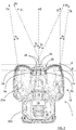
- FIG 1 shows a top view of a robotic working tool 1
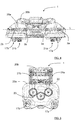
- Figure 4 shows a front view of the robotic working tool 1
- Figure 5 shows a bottom view of the robotic working tool 1, here exemplified by a robotic lawn mower 1.
- the robotic lawn mower 1 comprises a body 20a, 20b, a propulsion motor arrangement 15, a power source 16 such as a rechargeable battery adapted to provide power to the propulsion motor arrangement 15, and a plurality of wheels 17a, 17b; 21a, 21b, where two or more of the wheels, according to some aspects two rear wheels 21a, 21b, are adapted to be propelled by the propulsion motor arrangement 15, enabling the robotic working tool 1 to move with respect to a forward travelling direction D. It is of course possible that all four wheels 17a, 17b; 21a, 21b are adapted to be propelled by the propulsion motor arrangement 15.
- the robotic lawn mower 1 also comprises a grass cutting device 23, in this example a plurality of cutting blade arrangements driven by a cutter motor arrangement 22 that also is powered by the power source 16 or, alternatively, by a separate power source.
- the grass cutting device is an example of a general work tool for a robotic work tool.
- the propulsion motor arrangement 15 comprises one separate propulsion motor for each wheel 17a, 17b; 21a, 21b to be driven, and according to some further aspects, the cutter motor arrangement 22 comprises one separate cutter motor for each cutting blade arrangement.
- combustion engines may alternatively be used, possibly in combination with an electric motor.
- the robotic lawn mower 1 further comprises a control unit 18.
- the robotic lawn mower 1 may be a multi-chassis type or a mono-chassis type.
- a multi-chassis type comprises more than one body parts that are movable with respect to one another.
- a mono-chassis type comprises only one main body part. In this example there is a front body part 20a and a rear body part 20b.
- the robotic lawn mower 1 typically comprises charging skids 28 for contacting contact plates in a charging station when docking into the charging station for receiving a charging current through, and possibly also for transferring information by means of electrical communication between the charging station and the robotic lawn mower 1.
- Other means of establishing a charging contact are possible and are incorporated herein.
- the robotic lawn mower 1 is adapted to navigate with reference to a boundary wire emitting a magnetic field caused by a control signal transmitted through the boundary wire.
- the robotic lawn mower is further configured to detect the magnetic field and for detecting the boundary wire, for example by means of one or more magnetic field sensors. It is also conceivable that the robotic lawn mower 1 is adapted to navigate without a boundary wire, other navigation systems are conceivable, for example navigation systems based on GPS and/or one or more wireless communication systems.
- the robotic lawn mower 1 further comprises an environmental detection system 19 that comprises a set of outer detector transceivers 2a, 2b and a set of inner detector transceivers 3a, 3b.
- the inner detector transceivers 3a, 3b are positioned between the outer detector transceivers 2a, 2b along an extension E that is perpendicular to the forward travelling direction D.
- all detector transceivers 2a, 2b; 3a, 3b are positioned along the extension E, and one or more detector transceiver can according to some further aspects be mutually displaced along the forward travelling direction D.
- the inner detector transceivers 3a, 3b are displaced along the forward travelling direction D with respect to the outer detector transceivers 2a, 2b as will be discussed more later.
- the detector transceivers 2a, 2b; 3a, 3b are positioned along an extension that is inclined with respect to the forward travelling direction D, or that the detector transceivers 2a, 2b; 3a, 3b are positioned in an irregular manner.
- the inner detector transceivers 3a, 3b are positioned between the outer detector transceivers 2a, 2b along an extension and one or more detector transceiver can according to some further aspects be mutually displaced in a direction perpendicular to that extension.
- That extension can be any suitable extension, not having to be the extension E that is perpendicular to the forward travelling direction D.
- Each detector transceiver 2a, 2b; 3a, 3b is adapted to transmit signals 4a, 4b; 5a, 5b and to receive reflected signals 6a, 6b, 9 that have been reflected by an object 10, 11.
- the detector transceivers 2a, 2b; 3a, 3b are ultrasonic detector transceivers, being adapted to transmit and receive ultrasonic signals.
- the detector transceivers 2a, 2b; 3a, 3b can of any suitable kind such as for example radar transceivers or Lidar transceivers, applying a corresponding well-known technology for transmitting and receiving reflected signals.
- each detector transceiver 2a, 2b; 3a, 3b comprises a corresponding transmitter arrangement and receiver arrangement together with other necessary circuitry in a well-known manner.
- the detector transceivers 2a, 2b; 3a, 3b can be arranged in many ways within the scope of the present disclosure, according to some aspects there is a first outer detector transceiver 2a, a second outer detector transceiver 2b, a first inner detector transceiver 3a and a second inner detector transceiver 3b. According to some aspects, all detector transceivers 2a, 2b; 3a, 3b are positioned at a common horizontal level L as indicated in Figure 4 . Other position arrangements are of course conceivable.
- the outer detector transceivers 2a, 2b are associated with outer coverage main directions 7a, 7b that are directed at corresponding outer angles ⁇ a , ⁇ b to the forward travelling direction D
- the inner detector transceivers 3a, 3b are associated with inner coverage main directions 8a, 8b that are directed at corresponding inner angles ⁇ a , ⁇ b to the forward travelling direction D.
- the inner angles ⁇ a , ⁇ b have magnitudes that exceed the magnitudes of the outer angles ⁇ a , ⁇ b , and the inner coverage main directions 8a, 8b intersect in front of the outdoor robotic work tool 1 in the forward travelling direction D.
- the outer angles ⁇ a , ⁇ b are of the same magnitude and the inner angles ⁇ a , ⁇ b are of the same magnitude.
- the outer angles ⁇ a , ⁇ b are zero degrees, the outer coverage main directions 7a, 7b being parallel and coinciding with the forward travelling direction D.
- the outer angles ⁇ a , ⁇ b have a certain magnitude and are directed such that the outer coverage main directions 7a, 7b do not intersect in front of the outdoor robotic work tool 1 in the forward travelling direction D. It is also conceivable that the outer coverage main directions 7a, 7b do intersect in front of the outdoor robotic work tool 1.
- each coverage main direction 7a, 7b; 8a, 8b is associated with a corresponding transceiver coverage 12a, 12b; 13a, 13b, where the associated main direction 7a, 7b; 8a, 8b indicates a direction in which that transceiver coverage 12a, 12b; 13a, 13b has a maximum range.
- a combined rectangular coverage 14, having a certain width w, is formed in front of the outdoor robotic work tool 1 in the forward travelling direction D, where the combined coverage 14 comprises at least two separate transceiver coverages 12a, 12b; 13a, 13b.
- the width w is equal to or exceeds to a maximum width of the robotic lawn mower 1, where said width w extends in a direction orthogonal to the forward travelling direction D.
- the width w is shown to exceed the maximum width of the robotic lawn mower 1.
- a larger combined rectangular coverage 14, comprising at least two separate transceiver coverages 12a, 12b; 13a, 13b, is achieved than previously possible.
- This enables objects in the path of the robotic lawn mower 1 to be detected in an efficient and reliable manner, in particular earlier than previously possible, such that all obstacles are detected in time such that a collision can be avoided by stopping the robotic lawn mower 1 and/or turning the robotic lawn mower 1 away from the obstacle.
- the robotic lawn mower 1 comprises a control unit 18 that is adapted to control the detector transceivers 2a, 2b; 3a, 3b and to control the speed and direction of the robotic work tool 1 in dependence of information acquired by means of the of the detector transceivers 2a, 2b; 3a, 3b when the robotic lawn mower 1 is moving.
- the control unit 18 can be constituted by several separate control sub-units or one single integrated control unit.
- the control unit 18 is adapted to perform all necessary signal processing necessary for controlling the detector transceivers 2a, 2b; 3a, 3b and to acquire the desired information from the detected measurement results.
- At least the front body part 20a is movable and in contact with a collision sensor 24 as illustrated in Figure 1 and being adapted to detect that the front body part 20a has been displaced to such a degree that a collision most likely has occurred.
- a collision sensor 24 can be used for each one body part, preferably all body parts 20a, 20b, here only one collision sensor 24 is shown as an example.
- the control unit 18 that is adapted to control the speed and direction of the robotic work tool 1 in dependence of information from said collision sensor 24 s well, for example to reverse the movement direction when a possible collision has been detects.
- the robotic lawn mower 1 comprises a handle part 25 that is provided for lifting and handling the robotic lawn mower 1 when necessary, for example for service, inspection and/or cleaning.
- the handle part 25 is placed closer to the ground than the detector transceivers 2a, 2b; 3a, 3b when the robotic lawn mower 1 is operating, and is positioned in a front recess 26 such that it does not protrude as a frontmost part.
- first outer detector transceiver 2a and the second outer detector transceiver 2b are positioned closer to a front line F of the robotic lawn mower 1 than the first inner detector transceiver 3a and the second inner detector transceiver 3b, and in other words, the inner detector transceivers 3a, 3b are displaced along the forward travelling direction D with respect to the outer detector transceivers 2a, 2b.
- a front wheel pair 17a, 17b, the so-called caster wheels 17a, 17b can be arranged as close to the front line F as possible and as spaced apart as possible for increased stability of the robotic lawn mower 1.
- the detector transceivers 2a, 2b; 3a, 3b are adapted to transmit signals 4a, 4b; 5a, 5b at the same time.
- the first object 10 will be detected by the first outer detector transceiver 2a by means of a first signal 4a transmitted by the first outer detector transceiver 2a that results in a second signal 6a, reflected from the first object 10, that is received by the first outer detector transceiver 2a.
- the second object 11 will be detected by the second outer detector transceiver 2b since a third signal 5a transmitted by the first inner detector transceiver 3a results in a fourth signal 6b, reflected from the second object 11, that is received by the second outer detector transceiver 2b.
- the second object 11 will also be detected by the first inner detector transceiver 3a since a fifth signal 4b transmitted by the second outer detector transceiver 2b results in a sixth signal 9, reflected from the second object 10, that is received by the first inner detector transceiver 3a.
- the detector transceivers 2a, 2b; 3a, 3b are adapted to transmit signals 4a, 4b; 5a, 5b at the same time, detection of reflected signals will indicate the presence of one or more objects ahead, but not more specific details such as for example azimuth heading and/or distance, since a signal received at one detector transceivers can result from a signal transmitted from any one of the detector transceivers 2a, 2b; 3a, 3b. Normally it is sufficient for a robotic lawn mower 1 to be informed about the fact that there is one or more objects ahead in order to avoid a collision.
- each detector transceivers 2a, 2b; 3a, 3b can be adapted to transmit specific signals, such that a received signal can be identified with respect to its transmitting detector transceivers 2a, 2b; 3a, 3b.
- Such an identification can for example be accomplished by means of utilizing different waveforms or embedded identifications codes for the transmitted signals 4a, 4b, 5a, 5b.
- At least two detector transceivers 2a, 2b; 3a, 3b are adapted to transmit signals 4a, 4b; 5a, 5b and to receive reflected signals 6a, 6b, 9 that have been reflected by an object 10, 11, where the detector transceivers 2a, 2b; 3a, 3b are adapted to transmit signals 4a, 4b; 5a, 5b at least partly at the same time.
- the second inner detector transceiver 3b transmits a signal 5b where the transceiver coverage 13b indicated in Figure 1 implies that the signal 5b will be reflected by the first object 10, but where a reflected signal will travel away from the robotic lawn mower 1 and not be detected by any detector transceiver.
- FIG. 6 schematically illustrates, in terms of a number of functional units, the components of the control unit 18 according to embodiments of the discussions herein.
- Processing circuitry 27 is provided using any combination of one or more of a suitable central processing unit CPU, multiprocessor, microcontroller, digital signal processor DSP, etc., capable of executing software instructions stored in a computer program product, e.g. in the form of a storage medium 28.
- the processing circuitry 27 may further be provided as at least one application specific integrated circuit ASIC, or field programmable gate array FPGA.
- the processing circuitry thus comprises a plurality of digital logic components.
- the processing circuitry 27 is configured to cause the control unit 18 to perform a set of operations, or steps to control the operation of the robotic lawn mower 1 including, but not being limited to, controlling the detector transceivers 2a, 2b; 3a, 3b, processing measurements results received via the detector transceivers 2a, 2b; 3a, 3b, and the propulsion of the robotic lawn mower1.
- the storage medium 28 may store the set of operations
- the processing circuitry 27 may be configured to retrieve the set of operations from the storage medium 28 to cause the control unit 18 to perform the set of operations.
- the set of operations may be provided as a set of executable instructions.
- the processing circuitry 27 is thereby arranged to execute methods as herein disclosed.
- the storage medium 28 may also comprise persistent storage, which, for example, can be any single one or combination of magnetic memory, optical memory, solid state memory or even remotely mounted memory.
- control unit 18 further comprises an interface 29 for communications with at least one external device such as a control panel 30 or an external device.
- the interface 29 may comprise one or more transmitters and receivers, comprising analogue and digital components and a suitable number of ports for wireline communication.
- the interface 29 can be adapted for communication with other devices 34, such as a server, a personal computer or smartphone, the charging station, and/or other robotic working tools. Examples of such wireless communication devices are Bluetooth®, WiFi® (IEEE802.11b), Global System Mobile (GSM) and LTE (Long Term Evolution), to name a few.
- Figure 7 shows a computer program product 31 comprising computer executable instructions 32 stored on media 33 to execute any of the methods disclosed herein.
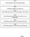
- the present disclosure also relates to a method in an outdoor robotic work tool 1 adapted for a forward travelling direction D, where the method comprises transmitting and receiving S100 reflected signals 6a, 6b, 9 that have been reflected by an object 10, 11 using at least two detector transceivers 2a, 2b; 3a, 3b, and transmitting S200 signals 4a, 4b; 5a, 5b at all detector transceivers 2a, 2b; 3a, 3b at least partly at the same time.
- the method further comprises transmitting S210 signals at the same time at all detector transceivers 2a, 2b; 3a, 3b.
- the method further comprises transmitting S220 signals at the same time at two or more detector transceivers, in the same or in different constellations at different times.
- the method further comprises transmitting S230 signals at only one detector transceiver 2a, 2b; 3a, 3b at a time at certain times.
- the method further comprises transmitting S240 a signal comprising a specific signal identification at each detector transceiver 2a, 2b; 3a, 3b, such that a received signal can be identified with respect to its transmitting detector transceiver 2a, 2b; 3a, 3b.
- the signal identification is accomplished by means of utilizing different waveforms or embedded identifications codes.
- the present disclosure relates to an outdoor robotic work tool 1 adapted for a forward travelling direction D and comprising an environmental detection system 19 that comprises a set of outer detector transceivers 2a, 2b and a set of inner detector transceivers 3a, 3b, where the inner detector transceivers 3a, 3b are positioned between the outer detector transceivers 2a, 2b.
- Each detector transceiver 2a, 2b; 3a, 3b is adapted to transmit signals 4a, 4b; 5a, 5b and to receive reflected signals 6a, 6b, 9 that have been reflected by an object 10, 11.
- the outer detector transceivers 2a, 2b are associated with outer coverage main directions 7a, 7b that are directed at corresponding outer angles ⁇ a , ⁇ b to the forward travelling direction D
- the inner detector transceivers 3a, 3b are associated with inner coverage main directions 8a, 8b that are directed at corresponding inner angles ⁇ a , ⁇ b to the forward travelling direction D.
- the inner angles ⁇ a , ⁇ b have magnitudes that exceed the magnitudes of the outer angles ⁇ a , ⁇ b
- the inner coverage main directions 8a, 8b intersect in front of the outdoor robotic work tool 1 in the forward travelling direction D.
- each coverage main direction 7a, 7b; 8a, 8b is associated with a corresponding transceiver coverage 12a, 12b; 13a, 13b, where a combined rectangular coverage 14 having a certain width w is formed in front of the outdoor robotic work tool 1 in the forward travelling direction D.
- the combined coverage 14 comprises at least two separate transceiver coverages 12a, 12b; 13a, 13b.
- the outer angles ⁇ a , ⁇ b are of the same magnitude and the inner angles ⁇ a , ⁇ b are of the same magnitude.
- the outer coverage main directions 7a, 7b do not intersect in front of the outdoor robotic work tool 1 in the forward travelling direction D.
- the outer coverage main directions 7a, 7b are mutually parallel.
- the detector transceivers 2a, 2b; 3a, 3b are adapted to transmit signals 4a, 4b; 5a, 5b at least partly at the same time.
- the detector transceivers 2a, 2b; 3a, 3b are any one of radar transceivers, ultrasonic transceivers or Lidar transceivers.
- the robotic work tool 1 is a robotic lawn mower.
- the robotic work tool 1 comprises a first outer detector transceiver 2a, a second outer detector transceiver 2b, a first inner detector transceiver 3a and a second inner detector transceiver 3b.
- the robotic work tool 1 comprises a propulsion motor arrangement 15, a power source 16 adapted to provide power to the propulsion motor arrangement 15, a plurality of wheels 17a, 17b; 21a, 21b where at least two wheels are adapted to be propelled by the propulsion motor arrangement 15, and a control unit 18 that is adapted to control the detector transceivers 2a, 2b; 3a, 3b and to control the speed and direction of the robotic work tool 1 in dependence of information acquired by means of the of the detector transceivers 2a, 2b; 3a, 3b when the robotic work tool 1 is moving.
- the present disclosure also relates to an outdoor robotic work tool 1 adapted for a forward travelling direction D and comprising an environmental detection system that comprises at least two detector transceivers 2a, 2b; 3a, 3b that are adapted to transmit signals 4a, 4b; 5a, 5b and to receive reflected signals 6a, 6b, 9 that have been reflected by an object 10, 11.
- the detector transceivers 2a, 2b; 3a, 3b are adapted to transmit signals 4a, 4b; 5a, 5b at least partly at the same time.
- the robotic work tool 1 comprises a set of outer detector transceivers 2a, 2b, a set of inner detector transceiver 3a, 3b, where the inner detector transceivers 3a, 3b are positioned between the outer detector transceivers 2a, 2b, where the outer detector transceivers 2a, 2b are associated with outer coverage main directions 7a, 7b that are directed at corresponding outer angles ⁇ a , ⁇ b to the forward travelling direction D, and the inner detector transceivers 3a, 3b are associated with inner coverage main directions 8a, 8b that are directed at corresponding inner angles ⁇ a , ⁇ b to the forward travelling direction D, wherein the inner angles ⁇ a , ⁇ b have magnitudes that exceed the magnitudes of the outer angles ⁇ a , ⁇ b , and where the inner coverage main directions 8a, 8b intersect in front of the outdoor robotic work tool 1 in the forward travelling direction D.
- the detector transceivers 2a, 2b; 3a, 3b are adapted to transmit signals at the same time at all detector transceivers 2a, 2b; 3a, 3b.
- the detector transceivers 2a, 2b; 3a, 3b are adapted to transmit signals at the same time at two or more detector transceivers, in the same or in different constellations at different times.
- the detector transceivers 2a, 2b; 3a, 3b are adapted to transmit signals at only one detector transceiver 2a, 2b; 3a, 3b at a time at certain times.
- each detector transceiver 2a, 2b; 3a, 3b is adapted to transmit a signal comprising a specific signal identification, such that a received signal can be identified with respect to its transmitting detector transceivers 2a, 2b; 3a, 3b.
- the signal identification is accomplished by means of utilizing different waveforms or embedded identifications codes.
- each detector transceivers 2a, 2b; 3a, 3b comprises associated well-known components such as a signal generator, a transmitting and receiving device such as a ultrasonic emitter/receiver arrangement or an transmitting/receiving antenna arrangement, and receiver circuitry.
- Each detector transceivers 2a, 2b; 3a, 3b can be directly controlled by the control unit 18, or comprise a sub-controller that is controlled by, and adapted to communicate with, the control unit 18.
Landscapes
- Engineering & Computer Science (AREA)
- Radar, Positioning & Navigation (AREA)
- Remote Sensing (AREA)
- Physics & Mathematics (AREA)
- General Physics & Mathematics (AREA)
- Aviation & Aerospace Engineering (AREA)
- Automation & Control Theory (AREA)
- Environmental Sciences (AREA)
- Life Sciences & Earth Sciences (AREA)
- Electromagnetism (AREA)
- Computer Networks & Wireless Communication (AREA)
- Acoustics & Sound (AREA)
- Optics & Photonics (AREA)
- Control Of Position, Course, Altitude, Or Attitude Of Moving Bodies (AREA)
- Harvester Elements (AREA)
- Manipulator (AREA)
- Guiding Agricultural Machines (AREA)
Abstract
Description
- The present disclosure relates to outdoor robotic work tool comprising an environmental detection system with a set of outer detector transceivers and a set of inner detector transceivers. The outdoor robotic work tool can for example be constituted by a robotic lawn mower.
- Automated or robotic power tools such as robotic lawn mowers are becoming increasingly more popular. In a typical deployment a work area, such as a garden, the work area is enclosed by a boundary wire with the purpose of keeping the robotic lawn mower inside the work area. An electric control signal may be transmitted through the boundary wire thereby generating an (electro-) magnetic field emanating from the boundary wire. The robotic working tool is typically arranged with one or more sensors adapted to sense the control signal.
- The robotic lawn mower can then cut grass on a user's lawn automatically and can be charged automatically without intervention of the user, and no longer needs to be manually managed after being set once. The robotic lawn mower needs to have a function of recognizing an obstacle to avoid colliding with the obstacle before encountering the obstacle, and to have a function of recognizing that a collision has occurred.
- In the latter case, a collision sensor can be disposed on the body of the robotic lawn mower, and when the robotic lawn mower collides with an obstacle, the body moves in such a way that the collision sensor generates a collision signal. In the former case, different kinds of environment detection sensors are use such as ultrasonic sensors as disclosed in
EP3508048 and radar sensors as disclosed inSE540794 - There is, however, a need to improve the coverage, reliably and efficiency of such environment detection sensors such that all obstacles are detected in time such that a collision can be avoided by stopping the robotic lawn mower and/or turning the robotic lawn mower away from the obstacle.
- The object of the present disclosure is to provide a robotic work tool with environment detection system that has an improved coverage, reliably and efficiency compared to prior art.
- This object is achieved by means of an outdoor robotic work tool adapted for a forward travelling direction and comprising an environmental detection system that comprises a set of outer detector transceivers and a set of inner detector transceivers, where the inner detector transceivers are positioned between the outer detector transceivers. Each detector transceiver is adapted to transmit signals and to receive reflected signals that have been reflected by an object. The outer detector transceivers are associated with outer coverage main directions that are directed at corresponding outer angles to the forward travelling direction, and the inner detector transceivers are associated with inner coverage main directions that are directed at corresponding inner angles to the forward travelling direction. The inner angles have magnitudes that exceed the magnitudes of the outer angles, and the inner coverage main directions intersect in front of the outdoor robotic work tool in the forward travelling direction.
- This means that a robotic work tool with an increased sensor coverage is provided, increasing the robotic work tool's ability to avoid collisions with other objects.
- According to some aspects, each coverage main direction is associated with a corresponding transceiver coverage, where a combined rectangular coverage having a certain width is formed in front of the outdoor robotic work tool in the forward travelling direction, where the combined coverage comprises at least two separate transceiver coverages.
- Forming such a combined area increases the reliability of the detections.
- According to some aspects, the outer angles are of the same magnitude and the inner angles are of the same magnitude.
- According to some aspects, the outer coverage main directions do not intersect in front of the outdoor robotic work tool in the forward travelling direction.
- In this way an increased coverage is enabled.
- According to some aspects, the outer coverage main directions are mutually parallel.
- In this way, a desirable combined area is formed.
- According to some aspects, the detector transceivers are adapted to transmit signals at least partly at the same time.
- In this way, objects in front of the robotic work tool are detected in a quicker and more efficient manner.
- According to some aspects, the detector transceivers are any one of radar transceivers, ultrasonic transceivers or Lidar transceivers.
- This means that the present disclosure is applicable for many types of detector transceivers.
- According to some aspects, the robotic work tool is a robotic lawn mower.
- According to some aspects, the robotic work tool comprises a first outer detector transceiver, a second outer detector transceiver, a first inner detector transceiver and a second inner detector transceiver.
- According to some aspects, the robotic work tool comprises a propulsion motor arrangement, a power source adapted to provide power to the propulsion motor arrangement and a plurality of wheels, where at least two wheels are adapted to be propelled by the propulsion motor arrangement. The robotic work tool further comprises a control unit that is adapted to control the detector transceivers and to control the speed and direction of the robotic work tool in dependence of information acquired by means of the of the detector transceivers when the robotic work tool is moving.
- In this manner, a safe and reliable control of the robotic work tool is provided.
- According to some aspects, the detector transceivers are adapted to transmit signals at the same time at all detector transceivers or at the same time at two or more detector transceivers, in the same or in different constellations at different times. Alternatively, or in combination, the detector transceivers are adapted to transmit signals at only one detector transceiver at a time at certain times.
- This means that the simultaneous transmission can be adapted either for different need that arise in dependence of detection results and/or in dependence of a certain predetermined scheduling.
- According to some aspects, each detector transceiver is adapted to transmit a signal comprising a specific signal identification, such that a received signal can be identified with respect to its transmitting detector transceivers. According to some aspects, the signal identification is accomplished by means of utilizing different waveforms or embedded identifications codes.
- In this way, specific details such as for example azimuth heading and/or distance can be provided for the detected objects.
- The present disclosure also relates to methods that are associated with above advantages.
- The present disclosure will now be described more in detail with reference to the appended drawings, where:
- Figure 1
- shows a first schematic top view of a lawn mower;
- Figure 2
- shows a second schematic top view of a lawn mower;
- Figure 3
- shows a third schematic top view of a lawn mower;
- Figure 4
- shows a schematic front view of a lawn mower;
- Figure 5
- shows a schematic bottom view of a lawn mower;
- Figure 6
- schematically illustrates processing circuitry;
- Figure 7
- shows a computer program product; and
- Figure 8
- shows a flowchart for methods according to the present disclosure.
- Aspects of the present disclosure will now be described more fully hereinafter with reference to the accompanying drawings. The different devices, systems, computer programs and methods disclosed herein can, however, be realized in many different forms and should not be construed as being limited to the aspects set forth herein. Like numbers in the drawings refer to like elements throughout.
- The terminology used herein is for describing aspects of the disclosure only and is not intended to limit the invention. As used herein, the singular forms "a", "an" and "the" are intended to include the plural forms as well, unless the context clearly indicates otherwise.
- It should be noted that even though the description given herein will be focused on robotic lawn mowers, the teachings herein may also be applied to any type of outdoor robotic work tool, such as for example robotic ball collectors, robotic mine sweepers and robotic farming equipment.
-
Figure 1 shows a top view of arobotic working tool 1,Figure 4 shows a front view of therobotic working tool 1 andFigure 5 shows a bottom view of therobotic working tool 1, here exemplified by arobotic lawn mower 1. Therobotic lawn mower 1 comprises abody propulsion motor arrangement 15, apower source 16 such as a rechargeable battery adapted to provide power to thepropulsion motor arrangement 15, and a plurality ofwheels rear wheels propulsion motor arrangement 15, enabling therobotic working tool 1 to move with respect to a forward travelling direction D. It is of course possible that all fourwheels propulsion motor arrangement 15. - The
robotic lawn mower 1 also comprises agrass cutting device 23, in this example a plurality of cutting blade arrangements driven by acutter motor arrangement 22 that also is powered by thepower source 16 or, alternatively, by a separate power source. The grass cutting device is an example of a general work tool for a robotic work tool. - According to some aspects, the
propulsion motor arrangement 15 comprises one separate propulsion motor for eachwheel cutter motor arrangement 22 comprises one separate cutter motor for each cutting blade arrangement. - It should be noted that even if the description herein is focused on electric motors, combustion engines may alternatively be used, possibly in combination with an electric motor.
- The
robotic lawn mower 1 further comprises acontrol unit 18. Therobotic lawn mower 1 may be a multi-chassis type or a mono-chassis type. A multi-chassis type comprises more than one body parts that are movable with respect to one another. A mono-chassis type comprises only one main body part. In this example there is afront body part 20a and arear body part 20b. - The
robotic lawn mower 1 typically comprises chargingskids 28 for contacting contact plates in a charging station when docking into the charging station for receiving a charging current through, and possibly also for transferring information by means of electrical communication between the charging station and therobotic lawn mower 1. Other means of establishing a charging contact are possible and are incorporated herein. - In a previously well-known manner, the
robotic lawn mower 1 is adapted to navigate with reference to a boundary wire emitting a magnetic field caused by a control signal transmitted through the boundary wire. The robotic lawn mower is further configured to detect the magnetic field and for detecting the boundary wire, for example by means of one or more magnetic field sensors. It is also conceivable that therobotic lawn mower 1 is adapted to navigate without a boundary wire, other navigation systems are conceivable, for example navigation systems based on GPS and/or one or more wireless communication systems. - The
robotic lawn mower 1 further comprises anenvironmental detection system 19 that comprises a set ofouter detector transceivers inner detector transceivers inner detector transceivers outer detector transceivers detector transceivers inner detector transceivers outer detector transceivers - It is also conceivable that the
detector transceivers detector transceivers inner detector transceivers outer detector transceivers - With reference also to
Figure 3 , Eachdetector transceiver signals reflected signals object detector transceivers detector transceivers detector transceiver - The
detector transceivers outer detector transceiver 2a, a secondouter detector transceiver 2b, a firstinner detector transceiver 3a and a secondinner detector transceiver 3b. According to some aspects, alldetector transceivers Figure 4 . Other position arrangements are of course conceivable. - With reference also to
Figure 2 , theouter detector transceivers main directions inner detector transceivers main directions - According to the present disclosure, the inner angles βa, βb have magnitudes that exceed the magnitudes of the outer angles αa, αb, and the inner coverage
main directions robotic work tool 1 in the forward travelling direction D. According to some aspects, the outer angles αa, αb are of the same magnitude and the inner angles βa, βb are of the same magnitude. - In
Figure 1 , in accordance with some aspects, the outer angles αa, αb are zero degrees, the outer coveragemain directions Figure 2 , in accordance with some aspects, the outer angles αa, αb have a certain magnitude and are directed such that the outer coveragemain directions robotic work tool 1 in the forward travelling direction D. It is also conceivable that the outer coveragemain directions robotic work tool 1. - As only shown in
Figure 1 for reasons of clarity, according to some aspects, each coveragemain direction corresponding transceiver coverage main direction transceiver coverage rectangular coverage 14, having a certain width w, is formed in front of the outdoorrobotic work tool 1 in the forward travelling direction D, where the combinedcoverage 14 comprises at least twoseparate transceiver coverages robotic lawn mower 1, where said width w extends in a direction orthogonal to the forward travelling direction D. InFigure 1 , the width w is shown to exceed the maximum width of therobotic lawn mower 1. - By means of the relation of the coverage
main directions rectangular coverage 14, comprising at least twoseparate transceiver coverages robotic lawn mower 1 to be detected in an efficient and reliable manner, in particular earlier than previously possible, such that all obstacles are detected in time such that a collision can be avoided by stopping therobotic lawn mower 1 and/or turning therobotic lawn mower 1 away from the obstacle. - For this purpose, as shown in
Figure 1 andFigure 2 , therobotic lawn mower 1 comprises acontrol unit 18 that is adapted to control thedetector transceivers robotic work tool 1 in dependence of information acquired by means of the of thedetector transceivers robotic lawn mower 1 is moving. Thecontrol unit 18 can be constituted by several separate control sub-units or one single integrated control unit. Thecontrol unit 18 is adapted to perform all necessary signal processing necessary for controlling thedetector transceivers - Should a collision occur anyway, at least the
front body part 20a is movable and in contact with acollision sensor 24 as illustrated inFigure 1 and being adapted to detect that thefront body part 20a has been displaced to such a degree that a collision most likely has occurred. One or more collision sensors can be used for each one body part, preferably allbody parts collision sensor 24 is shown as an example. Thecontrol unit 18 that is adapted to control the speed and direction of therobotic work tool 1 in dependence of information from said collision sensor 24 s well, for example to reverse the movement direction when a possible collision has been detects. - As indicated in
Figure 2 , in accordance with some aspects, therobotic lawn mower 1 comprises ahandle part 25 that is provided for lifting and handling therobotic lawn mower 1 when necessary, for example for service, inspection and/or cleaning. Thehandle part 25 is placed closer to the ground than thedetector transceivers robotic lawn mower 1 is operating, and is positioned in afront recess 26 such that it does not protrude as a frontmost part. This means that the firstouter detector transceiver 2a and the secondouter detector transceiver 2b are positioned closer to a front line F of therobotic lawn mower 1 than the firstinner detector transceiver 3a and the secondinner detector transceiver 3b, and in other words, theinner detector transceivers outer detector transceivers - As a consequence, the
handle part 25 does not disturb the operation of theinner detector transceivers front recess 26 is formed such that thefront body parts 20a does not disturb the operation of theinner detector transceivers front wheel pair caster wheels robotic lawn mower 1. - In accordance with some further aspects of the present disclosure, with reference to in particular
Figure 3 , thedetector transceivers signals first object 10 and asecond object 11 in front of therobotic lawn mower 1, thefirst object 10 will be detected by the firstouter detector transceiver 2a by means of afirst signal 4a transmitted by the firstouter detector transceiver 2a that results in asecond signal 6a, reflected from thefirst object 10, that is received by the firstouter detector transceiver 2a. - Furthermore, the
second object 11 will be detected by the secondouter detector transceiver 2b since athird signal 5a transmitted by the firstinner detector transceiver 3a results in afourth signal 6b, reflected from thesecond object 11, that is received by the secondouter detector transceiver 2b. Thesecond object 11 will also be detected by the firstinner detector transceiver 3a since afifth signal 4b transmitted by the secondouter detector transceiver 2b results in asixth signal 9, reflected from thesecond object 10, that is received by the firstinner detector transceiver 3a. - Since the
detector transceivers signals detector transceivers robotic lawn mower 1 to be informed about the fact that there is one or more objects ahead in order to avoid a collision. Should a more specific detection be desired and/or required, eachdetector transceivers detector transceivers signals - Generally, at least two
detector transceivers signals reflected signals object detector transceivers signals - the
detector transceivers - two or more detector transceivers transmit signals at the same time, in the same or in different constellations at different times, and/or
- at some times, only one
detector transceiver - This means that the simultaneous transmission can be adapted either for different need that arise in dependence of detection results and/or in dependence of a certain predetermined scheduling.
- Having a signal transmitted by one
detector transceiver detector transceivers object robotic lawn mower 1 is detected. - It should be noted that the second
inner detector transceiver 3b transmits asignal 5b where thetransceiver coverage 13b indicated inFigure 1 implies that thesignal 5b will be reflected by thefirst object 10, but where a reflected signal will travel away from therobotic lawn mower 1 and not be detected by any detector transceiver. -
Figure 6 schematically illustrates, in terms of a number of functional units, the components of thecontrol unit 18 according to embodiments of the discussions herein.Processing circuitry 27 is provided using any combination of one or more of a suitable central processing unit CPU, multiprocessor, microcontroller, digital signal processor DSP, etc., capable of executing software instructions stored in a computer program product, e.g. in the form of astorage medium 28. Theprocessing circuitry 27 may further be provided as at least one application specific integrated circuit ASIC, or field programmable gate array FPGA. The processing circuitry thus comprises a plurality of digital logic components. - Particularly, the
processing circuitry 27 is configured to cause thecontrol unit 18 to perform a set of operations, or steps to control the operation of therobotic lawn mower 1 including, but not being limited to, controlling thedetector transceivers detector transceivers storage medium 28 may store the set of operations, and theprocessing circuitry 27 may be configured to retrieve the set of operations from thestorage medium 28 to cause thecontrol unit 18 to perform the set of operations. The set of operations may be provided as a set of executable instructions. Thus, theprocessing circuitry 27 is thereby arranged to execute methods as herein disclosed. - The
storage medium 28 may also comprise persistent storage, which, for example, can be any single one or combination of magnetic memory, optical memory, solid state memory or even remotely mounted memory. - According to some aspects, the
control unit 18 further comprises aninterface 29 for communications with at least one external device such as acontrol panel 30 or an external device. As such theinterface 29 may comprise one or more transmitters and receivers, comprising analogue and digital components and a suitable number of ports for wireline communication. Theinterface 29 can be adapted for communication withother devices 34, such as a server, a personal computer or smartphone, the charging station, and/or other robotic working tools. Examples of such wireless communication devices are Bluetooth®, WiFi® (IEEE802.11b), Global System Mobile (GSM) and LTE (Long Term Evolution), to name a few. -
Figure 7 shows acomputer program product 31 comprising computerexecutable instructions 32 stored onmedia 33 to execute any of the methods disclosed herein. - With reference to
Figure 8 , the present disclosure also relates to a method in an outdoorrobotic work tool 1 adapted for a forward travelling direction D, where the method comprises transmitting and receiving S100 reflectedsignals object detector transceivers S200 signals detector transceivers - According to some aspects, the method further comprises transmitting S210 signals at the same time at all
detector transceivers - According to some aspects, the method further comprises transmitting S220 signals at the same time at two or more detector transceivers, in the same or in different constellations at different times.
- According to some aspects, the method further comprises transmitting S230 signals at only one
detector transceiver - According to some aspects, the method further comprises transmitting S240 a signal comprising a specific signal identification at each
detector transceiver detector transceiver - According to some aspects, the signal identification is accomplished by means of utilizing different waveforms or embedded identifications codes.
- Generally, the present disclosure relates to an outdoor
robotic work tool 1 adapted for a forward travelling direction D and comprising anenvironmental detection system 19 that comprises a set ofouter detector transceivers inner detector transceivers inner detector transceivers outer detector transceivers detector transceiver signals reflected signals object outer detector transceivers main directions inner detector transceivers main directions main directions robotic work tool 1 in the forward travelling direction D. - According to some aspects, each coverage
main direction corresponding transceiver coverage rectangular coverage 14 having a certain width w is formed in front of the outdoorrobotic work tool 1 in the forward travelling direction D. The combinedcoverage 14 comprises at least twoseparate transceiver coverages - According to some aspects, the outer angles αa, αb are of the same magnitude and the inner angles βa, βb are of the same magnitude.
- According to some aspects, the outer coverage
main directions robotic work tool 1 in the forward travelling direction D. - According to some aspects, the outer coverage
main directions - According to some aspects, the
detector transceivers signals - According to some aspects, the
detector transceivers - According to some aspects, the
robotic work tool 1 is a robotic lawn mower. - According to some aspects, the
robotic work tool 1 comprises a firstouter detector transceiver 2a, a secondouter detector transceiver 2b, a firstinner detector transceiver 3a and a secondinner detector transceiver 3b. - According to some aspects, the
robotic work tool 1 comprises apropulsion motor arrangement 15, apower source 16 adapted to provide power to thepropulsion motor arrangement 15, a plurality ofwheels propulsion motor arrangement 15, and acontrol unit 18 that is adapted to control thedetector transceivers robotic work tool 1 in dependence of information acquired by means of the of thedetector transceivers robotic work tool 1 is moving. - Generally, the present disclosure also relates to an outdoor
robotic work tool 1 adapted for a forward travelling direction D and comprising an environmental detection system that comprises at least twodetector transceivers signals reflected signals object detector transceivers signals - According to some aspects, the
robotic work tool 1 comprises a set ofouter detector transceivers inner detector transceiver inner detector transceivers outer detector transceivers outer detector transceivers main directions inner detector transceivers main directions main directions robotic work tool 1 in the forward travelling direction D. - According to some aspects, the
detector transceivers detector transceivers - According to some aspects, the
detector transceivers - According to some aspects, the
detector transceivers detector transceiver - According to some aspects, each
detector transceiver detector transceivers - According to some aspects, the signal identification is accomplished by means of utilizing different waveforms or embedded identifications codes.
- The present disclosure is not limited to the above, but may vary freely within the scope of the appended claims. For example, each
detector transceivers detector transceivers control unit 18, or comprise a sub-controller that is controlled by, and adapted to communicate with, thecontrol unit 18.
Claims (15)
- An outdoor robotic work tool (1) adapted for a forward travelling direction (D) and comprising an environmental detection system (19) that comprises a set of outer detector transceivers (2a, 2b) and a set of inner detector transceivers (3a, 3b), where the inner detector transceivers (3a, 3b) are positioned between the outer detector transceivers (2a, 2b), where each detector transceiver (2a, 2b; 3a, 3b) is adapted to transmit signals (4a, 4b; 5a, 5b) and to receive reflected signals (6a, 6b, 9) that have been reflected by an object (10, 11), wherein the outer detector transceivers (2a, 2b) are associated with outer coverage main directions (7a, 7b) that are directed at corresponding outer angles (αa, αb) to the forward travelling direction (D), and the inner detector transceivers (3a, 3b) are associated with inner coverage main directions (8a, 8b) that are directed at corresponding inner angles (βa, βb) to the forward travelling direction (D), wherein the inner angles (βa, βb) have magnitudes that exceed the magnitudes of the outer angles (αa, αb), and where the inner coverage main directions (8a, 8b) intersect in front of the outdoor robotic work tool (1) in the forward travelling direction (D).
- The outdoor robotic work tool (1) according to claim 1, wherein each coverage main direction (7a, 7b; 8a, 8b) is associated with a corresponding transceiver coverage (12a, 12b; 13a, 13b), where a combined rectangular coverage (14) having a certain width (w) is formed in front of the outdoor robotic work tool (1) in the forward travelling direction (D), where the combined coverage (14) comprises at least two separate transceiver coverages (12a, 12b; 13a, 13b).
- The outdoor robotic work tool (1) according to any one of the claims 1 or 2, wherein the outer angles (αa, αb) are of the same magnitude and the inner angles (βa, βb) are of the same magnitude.
- The outdoor robotic work tool (1) according to any one of the previous claims, wherein the outer coverage main directions (7a, 7b) do not intersect in front of the outdoor robotic work tool (1) in the forward travelling direction (D).
- The outdoor robotic work tool (1) according to any one of the previous claims, wherein the outer coverage main directions (7a, 7b) are mutually parallel.
- The outdoor robotic work tool (1) according to any one of the previous claims, wherein the detector transceivers (2a, 2b; 3a, 3b) are adapted to transmit signals (4a, 4b; 5a, 5b) at least partly at the same time.
- The outdoor robotic work tool (1) according to any one of the previous claims, wherein the detector transceivers (2a, 2b; 3a, 3b) are any one of radar transceivers, ultrasonic transceivers or Lidar transceivers.
- The outdoor robotic work tool (1) according to any one of the previous claims, wherein the robotic work tool (1) is a robotic lawn mower.
- The outdoor robotic work tool (1) according to any one of the previous claims, wherein the robotic work tool (1) comprises a first outer detector transceiver (2a), a second outer detector transceiver (2b), a first inner detector transceiver (3a) and a second inner detector transceiver (3b).
- The outdoor robotic work tool (1) according to any one of the previous claims, wherein the robotic work tool (1) comprises a propulsion motor arrangement (15), a power source (16) adapted to provide power to the propulsion motor arrangement (15), a plurality of wheels (17a, 17b; 21a, 21b) where at least two wheels are adapted to be propelled by the propulsion motor arrangement (15), and a control unit (18) that is adapted to control the detector transceivers (2a, 2b; 3a, 3b) and to control the speed and direction of the robotic work tool (1) in dependence of information acquired by means of the of the detector transceivers (2a, 2b; 3a, 3b) when the robotic work tool (1) is moving.
- An outdoor robotic work tool (1) adapted for a forward travelling direction (D) and comprising an environmental detection system that comprises at least two detector transceivers (2a, 2b; 3a, 3b) that are adapted to transmit signals (4a, 4b; 5a, 5b) and to receive reflected signals (6a, 6b, 9) that have been reflected by an object (10, 11), wherein the detector transceivers (2a, 2b; 3a, 3b) are adapted to transmit signals (4a, 4b; 5a, 5b) at least partly at the same time.
- The outdoor robotic work tool (1) according to claim 11, wherein the robotic work tool (1) comprises a set of outer detector transceivers (2a, 2b), a set of inner detector transceiver (3a, 3b), where the inner detector transceivers (3a, 3b) are positioned between the outer detector transceivers (2a, 2b), where the outer detector transceivers (2a, 2b) are associated with outer coverage main directions (7a, 7b) that are directed at corresponding outer angles (αa, αb) to the forward travelling direction (D), and the inner detector transceivers (3a, 3b) are associated with inner coverage main directions (8a, 8b) that are directed at corresponding inner angles (βa, βb) to the forward travelling direction (D), wherein the inner angles (βa, βb) have magnitudes that exceed the magnitudes of the outer angles (αa, αb), and where the inner coverage main directions (8a, 8b) intersect in front of the outdoor robotic work tool (1) in the forward travelling direction (D).
- The outdoor robotic work tool (1) according to any one of the claims 11 or 12, wherein each coverage main direction (7a, 7b; 8a, 8b) is associated with a corresponding transceiver coverage (12a, 12b; 13a, 13b), where a combined rectangular coverage (14) having a certain width (w) is formed in front of the outdoor robotic work tool (1) in the forward travelling direction (D), where the combined coverage (14) comprises at least two separate transceiver coverages (12a, 12b; 13a, 13b).
- The outdoor robotic work tool (1) according to any one of the claims 11-13, wherein the outer angles (αa, αb) are of the same magnitude and the inner angles (βa, βb) are of the same magnitude.
- The outdoor robotic work tool (1) according any one of the claims 11-14, wherein the outer coverage main directions (7a, 7b) do not intersect in front of the outdoor robotic work tool (1) in the forward travelling direction (D).
Applications Claiming Priority (1)
| Application Number | Priority Date | Filing Date | Title |
|---|---|---|---|
| SE2050539A SE544561C2 (en) | 2020-05-08 | 2020-05-08 | An outdoor robotic work tool comprising an environmental detection system |
Publications (2)
| Publication Number | Publication Date |
|---|---|
| EP3909412A1 true EP3909412A1 (en) | 2021-11-17 |
| EP3909412B1 EP3909412B1 (en) | 2025-04-02 |
Family
ID=75786938
Family Applications (1)
| Application Number | Title | Priority Date | Filing Date |
|---|---|---|---|
| EP21171761.6A Active EP3909412B1 (en) | 2020-05-08 | 2021-05-03 | An outdoor robotic work tool comprising an environmental detection system |
Country Status (4)
| Country | Link |
|---|---|
| US (1) | US11169530B1 (en) |
| EP (1) | EP3909412B1 (en) |
| CN (1) | CN113615376B (en) |
| SE (1) | SE544561C2 (en) |
Cited By (1)
| Publication number | Priority date | Publication date | Assignee | Title |
|---|---|---|---|---|
| SE2250671A1 (en) * | 2022-06-03 | 2023-12-04 | Husqvarna Ab | Enhanced drive motor control in a robotic lawnmower |
Families Citing this family (8)
| Publication number | Priority date | Publication date | Assignee | Title |
|---|---|---|---|---|
| US12296694B2 (en) | 2021-03-10 | 2025-05-13 | Techtronic Cordless Gp | Lawnmowers |
| US12443180B2 (en) | 2021-11-10 | 2025-10-14 | Techtronic Cordless Gp | Robotic lawn mowers |
| AU2023200381A1 (en) | 2022-01-31 | 2023-08-17 | Techtronic Cordless Gp | Robotic garden tool |
| EP4270138A1 (en) | 2022-04-28 | 2023-11-01 | Techtronic Cordless GP | Creation of a virtual boundary for a robotic garden tool |
| US12472611B2 (en) | 2022-05-31 | 2025-11-18 | Techtronic Cordless Gp | Peg driver |
| AU2023204696A1 (en) | 2022-07-19 | 2024-02-08 | Techtronic Cordless Gp | Display for controlling robotic tool |
| EP4340296B1 (en) | 2022-07-29 | 2025-04-09 | Techtronic Cordless GP | Generation of a cryptography key for a robotic garden tool |
| US20250072317A1 (en) * | 2023-08-28 | 2025-03-06 | Deere & Company | Mower obstacle avoidance system |
Citations (6)
| Publication number | Priority date | Publication date | Assignee | Title |
|---|---|---|---|---|
| US7047132B2 (en) * | 2004-01-12 | 2006-05-16 | Steven Jacobs | Mobile vehicle sensor array |
| KR20080027675A (en) * | 2006-09-25 | 2008-03-28 | 엘지전자 주식회사 | Robot cleaner and control method accordingly |
| CN103941735A (en) * | 2014-05-05 | 2014-07-23 | 苏州爱普电器有限公司 | Floor cleaning robot and method for controlling robot to avoid obstacle |
| SE540794C2 (en) | 2017-02-06 | 2018-11-13 | Acconeer Ab | An autonomous mobile robot with radar sensors |
| EP3508048A1 (en) | 2016-08-31 | 2019-07-10 | Positec Power Tools (Suzhou) Co., Ltd | Intelligent lawn-mower, self-mobile device and obstacle identify method thereof |
| CN209417594U (en) * | 2017-08-30 | 2019-09-20 | 苏州宝时得电动工具有限公司 | From mobile device |
Family Cites Families (34)
| Publication number | Priority date | Publication date | Assignee | Title |
|---|---|---|---|---|
| JPS5432778A (en) * | 1977-08-19 | 1979-03-10 | Hitachi Ltd | Ultrasonic switch |
| US4189903A (en) | 1978-06-23 | 1980-02-26 | Mcdonough Power Equipment, Division Of Fuqua Industries, Inc. | Rotary lawn mower with removable mulching attachment |
| US4232505A (en) | 1978-08-09 | 1980-11-11 | The Toro Company | Dual element filament mower |
| US5211722A (en) | 1989-08-01 | 1993-05-18 | Wagner John W | Divot anchoring process |
| JP2534714Y2 (en) | 1991-07-18 | 1997-05-07 | 川崎重工業株式会社 | Induction wires for self-propelled lawnmowers |
| GB9118637D0 (en) | 1991-08-30 | 1991-10-16 | Electrolux Northern | Improvements in and relating to grass cutting machines |
| US5212938A (en) | 1991-11-27 | 1993-05-25 | The Toro Company | Mulching mower with obround cutting chamber |
| JPH0787823A (en) | 1993-09-27 | 1995-04-04 | Kubota Corp | Moor |
| GB2289848A (en) | 1994-05-28 | 1995-12-06 | John Paul Greenwood | Divot retainer |
| US5638668A (en) | 1995-06-26 | 1997-06-17 | The Toro Company | Lawn mower having nested deck and liner |
| IL124413A (en) * | 1998-05-11 | 2001-05-20 | Friendly Robotics Ltd | System and method for area coverage with an autonomous robot |
| US8412377B2 (en) * | 2000-01-24 | 2013-04-02 | Irobot Corporation | Obstacle following sensor scheme for a mobile robot |
| WO2003013223A1 (en) | 2001-08-09 | 2003-02-20 | Kevin Henry Rix-Trott | Ground surface covers |
| US6899501B2 (en) | 2003-02-26 | 2005-05-31 | Bellsouth Intellectual Property Corporation | Fastener for fastening a length of wire to the ground |
| US20040202512A1 (en) | 2003-04-10 | 2004-10-14 | Smith Michael C. | Ground anchor for use with natural ground cover |
| JP2006084428A (en) * | 2004-09-17 | 2006-03-30 | Denso Corp | Obstacle detection device |
| EP1827075A2 (en) | 2004-12-14 | 2007-09-05 | Uzet Patents Limited | A stake |
| ES2346343T3 (en) * | 2005-02-18 | 2010-10-14 | Irobot Corporation | AUTONOMOUS SURFACE CLEANING ROBOT FOR DRY AND WET CLEANING. |
| US7877166B2 (en) * | 2005-06-28 | 2011-01-25 | S.C. Johnson & Son, Inc. | RFID navigational system for robotic floor treater |
| JP2007193538A (en) * | 2006-01-18 | 2007-08-02 | Sharp Corp | Self-propelled mobile |
| CN101091428A (en) * | 2006-10-20 | 2007-12-26 | 大连理工大学 | Automatic mowing robot |
| US8336282B2 (en) | 2010-07-28 | 2012-12-25 | Deere & Company | Robotic mower housing |
| EP2869691B1 (en) | 2012-07-04 | 2017-08-23 | Husqvarna Ab | Secured screw-nut interface for a robotic mower |
| WO2014007729A1 (en) | 2012-07-05 | 2014-01-09 | Husqvarna Ab | Modular robotic vehicle |
| CN103141210B (en) * | 2013-03-13 | 2015-04-01 | 江苏春花杰佳电器有限公司 | Intelligent grass cutter system and grass cutting method |
| CN206950128U (en) * | 2013-12-18 | 2018-02-02 | 艾罗伯特公司 | Autonomous mobile robot |
| US10391637B2 (en) * | 2014-06-25 | 2019-08-27 | Miraikikai, Inc. | Self-propelled robot |
| US9919425B2 (en) * | 2015-07-01 | 2018-03-20 | Irobot Corporation | Robot navigational sensor system |
| JP6546289B2 (en) | 2015-12-24 | 2019-07-17 | 本田技研工業株式会社 | Lawn mower |
| WO2017171046A1 (en) * | 2016-03-31 | 2017-10-05 | 株式会社未来機械 | Work robot and edge detector |
| CN205946577U (en) | 2016-08-19 | 2017-02-15 | 深圳市银星智能科技股份有限公司 | Mowing robot |
| CN208016344U (en) * | 2017-08-30 | 2018-10-30 | 苏州宝时得电动工具有限公司 | Automatic running device |
| WO2019157841A1 (en) * | 2018-02-13 | 2019-08-22 | 杭州慧慧科技有限公司 | Mower robot, mower working area generation system, generation method, obstacle avoiding device and automated mowing system |
| SE543861C2 (en) | 2019-02-22 | 2021-08-17 | Husqvarna Ab | Robotic lawnmower with folding mechanism allowing a cutting unit to be pivoted relative a driving unit |
-
2020
- 2020-05-08 SE SE2050539A patent/SE544561C2/en not_active IP Right Cessation
-
2021
- 2021-04-29 CN CN202110477424.7A patent/CN113615376B/en not_active Expired - Fee Related
- 2021-05-03 EP EP21171761.6A patent/EP3909412B1/en active Active
- 2021-05-06 US US17/313,207 patent/US11169530B1/en not_active Expired - Fee Related
Patent Citations (7)
| Publication number | Priority date | Publication date | Assignee | Title |
|---|---|---|---|---|
| US7047132B2 (en) * | 2004-01-12 | 2006-05-16 | Steven Jacobs | Mobile vehicle sensor array |
| KR20080027675A (en) * | 2006-09-25 | 2008-03-28 | 엘지전자 주식회사 | Robot cleaner and control method accordingly |
| CN103941735A (en) * | 2014-05-05 | 2014-07-23 | 苏州爱普电器有限公司 | Floor cleaning robot and method for controlling robot to avoid obstacle |
| EP3508048A1 (en) | 2016-08-31 | 2019-07-10 | Positec Power Tools (Suzhou) Co., Ltd | Intelligent lawn-mower, self-mobile device and obstacle identify method thereof |
| US20190265724A1 (en) * | 2016-08-31 | 2019-08-29 | Positec Power Tools (Suzhou) Co., Ltd. | Autonomous Lawn Mower, Self-Moving Device, and Method for Recognizing Obstacle By Same |
| SE540794C2 (en) | 2017-02-06 | 2018-11-13 | Acconeer Ab | An autonomous mobile robot with radar sensors |
| CN209417594U (en) * | 2017-08-30 | 2019-09-20 | 苏州宝时得电动工具有限公司 | From mobile device |
Cited By (2)
| Publication number | Priority date | Publication date | Assignee | Title |
|---|---|---|---|---|
| SE2250671A1 (en) * | 2022-06-03 | 2023-12-04 | Husqvarna Ab | Enhanced drive motor control in a robotic lawnmower |
| SE546203C2 (en) * | 2022-06-03 | 2024-07-02 | Husqvarna Ab | Method for controlling a robotic lawnmower in dependence of analysis of information acquired by means of a radar transceiver and a control unit therefor |
Also Published As
| Publication number | Publication date |
|---|---|
| CN113615376B (en) | 2022-11-22 |
| SE544561C2 (en) | 2022-07-19 |
| EP3909412B1 (en) | 2025-04-02 |
| US11169530B1 (en) | 2021-11-09 |
| US20210349464A1 (en) | 2021-11-11 |
| SE2050539A1 (en) | 2021-11-09 |
| CN113615376A (en) | 2021-11-09 |
Similar Documents
| Publication | Publication Date | Title |
|---|---|---|
| US11169530B1 (en) | Outdoor robotic work tool comprising an environmental detection system | |
| EP4118509B1 (en) | System and method for improved navigation of a robotic work tool | |
| EP3161571B1 (en) | Improved robotic working tool | |
| EP3373097B1 (en) | Robotic mower with object detection system | |
| CN102811604B (en) | For robotic garden tool being guided to the method and system in precalculated position | |
| EP3236734B1 (en) | Improved operation of a robotic work tool by adapting the operation to weather conditions | |
| EP4072261B1 (en) | Exit path determination for a robotic work tool | |
| EP4000367B1 (en) | An energy efficient robotic lawn mower | |
| CN106444736B (en) | Automatic return system and control method | |
| SE1950956A1 (en) | Improved operation for a robotic work tool | |
| EP3143469B1 (en) | Automatic sensitivity adjustment in object detection system | |
| EP4419976B1 (en) | Improved navigation for a robotic lawnmower | |
| CN209417595U (en) | From mobile device | |
| US20230176584A1 (en) | Guidance for an outdoor robotic work tool to an outdoor robotic work tool interaction station | |
| SE2051308A1 (en) | Improved edge operation for a robotic work tool | |
| WO2023234820A1 (en) | Enhanced drive motor control in a robotic lawnmower | |
| EP4470356A1 (en) | Efficient charging of an outdoor robotic work tool | |
| SE2250230A1 (en) | An outdoor robotic work tool comprising an environmental detection system adapted to detect obstacles | |
| EP4537649A1 (en) | A robotic lawn mower system with enhanced boundary cutting | |
| EP4596304A2 (en) | Means and methods for enhanced robotic work tool charging | |
| EP4562994A1 (en) | Enhanced surface detection for a robotic lawnmower | |
| US20230359221A1 (en) | Navigation for a robotic work tool system | |
| US20250359507A1 (en) | Robotic lawn mower with enhanced cutting properties in slopes | |
| SE545376C2 (en) | Navigation for a robotic work tool system | |
| SE2350697A1 (en) | Improved navigation for a robotic work tool system |
Legal Events
| Date | Code | Title | Description |
|---|---|---|---|
| PUAI | Public reference made under article 153(3) epc to a published international application that has entered the european phase |
Free format text: ORIGINAL CODE: 0009012 |
|
| STAA | Information on the status of an ep patent application or granted ep patent |
Free format text: STATUS: REQUEST FOR EXAMINATION WAS MADE |
|
| 17P | Request for examination filed |
Effective date: 20210503 |
|
| AK | Designated contracting states |
Kind code of ref document: A1 Designated state(s): AL AT BE BG CH CY CZ DE DK EE ES FI FR GB GR HR HU IE IS IT LI LT LU LV MC MK MT NL NO PL PT RO RS SE SI SK SM TR |
|
| B565 | Issuance of search results under rule 164(2) epc |
Effective date: 20211018 |
|
| STAA | Information on the status of an ep patent application or granted ep patent |
Free format text: STATUS: EXAMINATION IS IN PROGRESS |
|
| 17Q | First examination report despatched |
Effective date: 20240816 |
|
| GRAP | Despatch of communication of intention to grant a patent |
Free format text: ORIGINAL CODE: EPIDOSNIGR1 |
|
| STAA | Information on the status of an ep patent application or granted ep patent |
Free format text: STATUS: GRANT OF PATENT IS INTENDED |
|
| RIC1 | Information provided on ipc code assigned before grant |
Ipc: G01S 17/93 20200101ALN20250113BHEP Ipc: A01D 75/18 20060101ALI20250113BHEP Ipc: A01D 34/00 20060101AFI20250113BHEP |
|
| GRAS | Grant fee paid |
Free format text: ORIGINAL CODE: EPIDOSNIGR3 |
|
| INTG | Intention to grant announced |
Effective date: 20250128 |
|
| GRAA | (expected) grant |
Free format text: ORIGINAL CODE: 0009210 |
|
| STAA | Information on the status of an ep patent application or granted ep patent |
Free format text: STATUS: THE PATENT HAS BEEN GRANTED |
|
| P01 | Opt-out of the competence of the unified patent court (upc) registered |
Free format text: CASE NUMBER: APP_5512/2025 Effective date: 20250203 |
|
| AK | Designated contracting states |
Kind code of ref document: B1 Designated state(s): AL AT BE BG CH CY CZ DE DK EE ES FI FR GB GR HR HU IE IS IT LI LT LU LV MC MK MT NL NO PL PT RO RS SE SI SK SM TR |
|
| REG | Reference to a national code |
Ref country code: GB Ref legal event code: FG4D |
|
| REG | Reference to a national code |
Ref country code: CH Ref legal event code: EP |
|
| REG | Reference to a national code |
Ref country code: DE Ref legal event code: R096 Ref document number: 602021028387 Country of ref document: DE |
|
| REG | Reference to a national code |
Ref country code: IE Ref legal event code: FG4D |
|
| PGFP | Annual fee paid to national office [announced via postgrant information from national office to epo] |
Ref country code: DE Payment date: 20250409 Year of fee payment: 5 |
|
| PGFP | Annual fee paid to national office [announced via postgrant information from national office to epo] |
Ref country code: GB Payment date: 20250411 Year of fee payment: 5 |
|
| PGFP | Annual fee paid to national office [announced via postgrant information from national office to epo] |
Ref country code: FR Payment date: 20250414 Year of fee payment: 5 |
|
| PGFP | Annual fee paid to national office [announced via postgrant information from national office to epo] |
Ref country code: AT Payment date: 20250721 Year of fee payment: 5 |
|
| REG | Reference to a national code |
Ref country code: NL Ref legal event code: MP Effective date: 20250402 |
|
| PG25 | Lapsed in a contracting state [announced via postgrant information from national office to epo] |
Ref country code: NL Free format text: LAPSE BECAUSE OF FAILURE TO SUBMIT A TRANSLATION OF THE DESCRIPTION OR TO PAY THE FEE WITHIN THE PRESCRIBED TIME-LIMIT Effective date: 20250402 |
|
| REG | Reference to a national code |
Ref country code: AT Ref legal event code: MK05 Ref document number: 1780329 Country of ref document: AT Kind code of ref document: T Effective date: 20250402 |
|
| PG25 | Lapsed in a contracting state [announced via postgrant information from national office to epo] |
Ref country code: PT Free format text: LAPSE BECAUSE OF FAILURE TO SUBMIT A TRANSLATION OF THE DESCRIPTION OR TO PAY THE FEE WITHIN THE PRESCRIBED TIME-LIMIT Effective date: 20250804 Ref country code: FI Free format text: LAPSE BECAUSE OF FAILURE TO SUBMIT A TRANSLATION OF THE DESCRIPTION OR TO PAY THE FEE WITHIN THE PRESCRIBED TIME-LIMIT Effective date: 20250402 Ref country code: ES Free format text: LAPSE BECAUSE OF FAILURE TO SUBMIT A TRANSLATION OF THE DESCRIPTION OR TO PAY THE FEE WITHIN THE PRESCRIBED TIME-LIMIT Effective date: 20250402 |
|
| REG | Reference to a national code |
Ref country code: LT Ref legal event code: MG9D |
|
| PG25 | Lapsed in a contracting state [announced via postgrant information from national office to epo] |
Ref country code: NO Free format text: LAPSE BECAUSE OF FAILURE TO SUBMIT A TRANSLATION OF THE DESCRIPTION OR TO PAY THE FEE WITHIN THE PRESCRIBED TIME-LIMIT Effective date: 20250702 Ref country code: GR Free format text: LAPSE BECAUSE OF FAILURE TO SUBMIT A TRANSLATION OF THE DESCRIPTION OR TO PAY THE FEE WITHIN THE PRESCRIBED TIME-LIMIT Effective date: 20250703 |
|
| PG25 | Lapsed in a contracting state [announced via postgrant information from national office to epo] |
Ref country code: PL Free format text: LAPSE BECAUSE OF FAILURE TO SUBMIT A TRANSLATION OF THE DESCRIPTION OR TO PAY THE FEE WITHIN THE PRESCRIBED TIME-LIMIT Effective date: 20250402 |
|
| PG25 | Lapsed in a contracting state [announced via postgrant information from national office to epo] |
Ref country code: BG Free format text: LAPSE BECAUSE OF FAILURE TO SUBMIT A TRANSLATION OF THE DESCRIPTION OR TO PAY THE FEE WITHIN THE PRESCRIBED TIME-LIMIT Effective date: 20250402 |
|
| PG25 | Lapsed in a contracting state [announced via postgrant information from national office to epo] |
Ref country code: HR Free format text: LAPSE BECAUSE OF FAILURE TO SUBMIT A TRANSLATION OF THE DESCRIPTION OR TO PAY THE FEE WITHIN THE PRESCRIBED TIME-LIMIT Effective date: 20250402 |
|
| PG25 | Lapsed in a contracting state [announced via postgrant information from national office to epo] |
Ref country code: AT Free format text: LAPSE BECAUSE OF FAILURE TO SUBMIT A TRANSLATION OF THE DESCRIPTION OR TO PAY THE FEE WITHIN THE PRESCRIBED TIME-LIMIT Effective date: 20250402 |
|
| PG25 | Lapsed in a contracting state [announced via postgrant information from national office to epo] |
Ref country code: RS Free format text: LAPSE BECAUSE OF FAILURE TO SUBMIT A TRANSLATION OF THE DESCRIPTION OR TO PAY THE FEE WITHIN THE PRESCRIBED TIME-LIMIT Effective date: 20250702 |
|
| PG25 | Lapsed in a contracting state [announced via postgrant information from national office to epo] |
Ref country code: IS Free format text: LAPSE BECAUSE OF FAILURE TO SUBMIT A TRANSLATION OF THE DESCRIPTION OR TO PAY THE FEE WITHIN THE PRESCRIBED TIME-LIMIT Effective date: 20250802 |
|
| PG25 | Lapsed in a contracting state [announced via postgrant information from national office to epo] |
Ref country code: LV Free format text: LAPSE BECAUSE OF FAILURE TO SUBMIT A TRANSLATION OF THE DESCRIPTION OR TO PAY THE FEE WITHIN THE PRESCRIBED TIME-LIMIT Effective date: 20250402 |
|
| REG | Reference to a national code |
Ref country code: CH Ref legal event code: H13 Free format text: ST27 STATUS EVENT CODE: U-0-0-H10-H13 (AS PROVIDED BY THE NATIONAL OFFICE) Effective date: 20251223 |
|
| REG | Reference to a national code |
Ref country code: DE Ref legal event code: R097 Ref document number: 602021028387 Country of ref document: DE |
|
| PG25 | Lapsed in a contracting state [announced via postgrant information from national office to epo] |
Ref country code: DK Free format text: LAPSE BECAUSE OF FAILURE TO SUBMIT A TRANSLATION OF THE DESCRIPTION OR TO PAY THE FEE WITHIN THE PRESCRIBED TIME-LIMIT Effective date: 20250402 Ref country code: SM Free format text: LAPSE BECAUSE OF FAILURE TO SUBMIT A TRANSLATION OF THE DESCRIPTION OR TO PAY THE FEE WITHIN THE PRESCRIBED TIME-LIMIT Effective date: 20250402 |
|
| PG25 | Lapsed in a contracting state [announced via postgrant information from national office to epo] |
Ref country code: LU Free format text: LAPSE BECAUSE OF NON-PAYMENT OF DUE FEES Effective date: 20250503 |
|
| PG25 | Lapsed in a contracting state [announced via postgrant information from national office to epo] |
Ref country code: CH Free format text: LAPSE BECAUSE OF NON-PAYMENT OF DUE FEES Effective date: 20250531 |
|
| PG25 | Lapsed in a contracting state [announced via postgrant information from national office to epo] |
Ref country code: CZ Free format text: LAPSE BECAUSE OF FAILURE TO SUBMIT A TRANSLATION OF THE DESCRIPTION OR TO PAY THE FEE WITHIN THE PRESCRIBED TIME-LIMIT Effective date: 20250402 |
|
| PG25 | Lapsed in a contracting state [announced via postgrant information from national office to epo] |
Ref country code: EE Free format text: LAPSE BECAUSE OF FAILURE TO SUBMIT A TRANSLATION OF THE DESCRIPTION OR TO PAY THE FEE WITHIN THE PRESCRIBED TIME-LIMIT Effective date: 20250402 |
|
| PG25 | Lapsed in a contracting state [announced via postgrant information from national office to epo] |
Ref country code: SK Free format text: LAPSE BECAUSE OF FAILURE TO SUBMIT A TRANSLATION OF THE DESCRIPTION OR TO PAY THE FEE WITHIN THE PRESCRIBED TIME-LIMIT Effective date: 20250402 Ref country code: RO Free format text: LAPSE BECAUSE OF FAILURE TO SUBMIT A TRANSLATION OF THE DESCRIPTION OR TO PAY THE FEE WITHIN THE PRESCRIBED TIME-LIMIT Effective date: 20250402 |
|
| PG25 | Lapsed in a contracting state [announced via postgrant information from national office to epo] |
Ref country code: IT Free format text: LAPSE BECAUSE OF FAILURE TO SUBMIT A TRANSLATION OF THE DESCRIPTION OR TO PAY THE FEE WITHIN THE PRESCRIBED TIME-LIMIT Effective date: 20250402 |
|
| REG | Reference to a national code |
Ref country code: BE Ref legal event code: MM Effective date: 20250531 |
|
| PG25 | Lapsed in a contracting state [announced via postgrant information from national office to epo] |
Ref country code: MC Free format text: LAPSE BECAUSE OF FAILURE TO SUBMIT A TRANSLATION OF THE DESCRIPTION OR TO PAY THE FEE WITHIN THE PRESCRIBED TIME-LIMIT Effective date: 20250402 |
|
| PLBE | No opposition filed within time limit |
Free format text: ORIGINAL CODE: 0009261 |
|
| STAA | Information on the status of an ep patent application or granted ep patent |
Free format text: STATUS: NO OPPOSITION FILED WITHIN TIME LIMIT |
|
| REG | Reference to a national code |
Ref country code: CH Ref legal event code: L10 Free format text: ST27 STATUS EVENT CODE: U-0-0-L10-L00 (AS PROVIDED BY THE NATIONAL OFFICE) Effective date: 20260211 |
|
| 26N | No opposition filed |
Effective date: 20260105 |
|
| PG25 | Lapsed in a contracting state [announced via postgrant information from national office to epo] |
Ref country code: IE Free format text: LAPSE BECAUSE OF NON-PAYMENT OF DUE FEES Effective date: 20250503 |
|
| PG25 | Lapsed in a contracting state [announced via postgrant information from national office to epo] |
Ref country code: BE Free format text: LAPSE BECAUSE OF NON-PAYMENT OF DUE FEES Effective date: 20250531 |